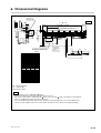
1
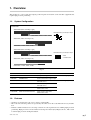
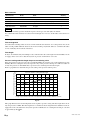
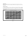
Scale Unit
SR84 / SR85, CH33
Read all the instructions in the manual carefully before use and strictly follow them.
Keep the manual for future references.
Instruction Manual
SR84 / SR85, CH33
Safety Precautions
Magnescale Co., Ltd. products are designed in full consideration of safety. However, improper
handling during operation or installation is dangerous and may lead to fire, electric shock or
other accidents resulting in serious injury or death. In addition, these actions may also worsen
machine performance.
Therefore, be sure to observe the following safety precautions in order to prevent these types of
accidents, and to read these “Safety Precautions” before operating, installing, maintaining, inspecting, repairing or otherwise working on this unit.
Warning indication meanings
The following indications are used throughout this manual, and their contents should be understood before reading the text.
Warning
Failure to observe these precautions may lead to fire, electric shock or other accidents resulting
in serious injury or death.
Caution
Failure to observe these precautions may lead to electric shock or other accidents resulting in
injury or damage to surrounding objects.
Warning
• Do not use this unit with voltages other than the specified supply voltages as this may
result in fire or electric shock.
• Do not perform installation work with wet hands as this may result in electric shock.
• Do not disassemble or modify the unit as this may result in injury or damage the
internal circuits.
SR84 / SR85, CH33
(E) (1)
Caution
• Be sure to check the machine and device conditions to ensure work safety before
working on the machine.
• Be sure to cut off the power supply and other sources of drive power before working
on the machine. Failure to do so may result in fire or accidents.
• When turning on the power supply or other sources of drive power to operate the
machine, take care not to catch your fingers in peripheral machines and devices.
General Precautions
When using Magnescale Co., Ltd. products, observe the following general precautions along with those given
specifically in this manual to ensure proper use of the products.
• Before and during operations, be sure to check that our products function properly.
• Provide adequate safety measures to prevent damages in case our products should develop malfunctions.
• Use outside indicated specifications or purposes and modification of our products will void any warranty of the
functions and performance as specified of our products.
• When using our products in combination with other equipment, the functions and performance as noted in this
manual may not be attained, depending upon operating environmental conditions. Make full study of the compatibility in advance.
(2) (E)
SR84 / SR85, CH33
[For U.S.A. and Canada]
[ For EU and EFTA countries ]
THIS CLASS A DIGITAL DEVICE COMPLIES WITH
PART15 OF THE FCC RULES AND THE CANADIAN
ICES-003. OPERATION IS SUBJECT TO THE
FOLLOWING TWO CONDITIONS.
(1) THIS DEVICE MAY NOT CAUSE HARMFUL
INTERFERENCE, AND
(2) T H I S D E V I C E M U S T A C C E P T A N Y
INTERFERENCE RECEIVED, INCLUDING
INTERFERENCE THAT MAY CAUSE
UNDERSIGNED OPERATION.
CE Notice
Marking by the symbol CE indicates compliance with
the EMC directive of the European Community. This
marking shows conformity to the following technical
standards.
EN 55011 Group 1 Class A/1998 A1/1999 A2/2002 :
"Limits and methods of measurement of radio
disturbance characteristics of industrial, scientific and
medical (ISM) radio-frequency equipment"
EN 61000-6-2/2001 :
CET APPAREIL NUMÉRIQUE DE LA CLASSE A
EST CONFORME À LA NORME NMB-003 DU
CANADA.
"Electromagnetic compatibility (EMC) - Part 6-2 :
Generic standards - Immunity for industrial
environments"
警告
本装置を機械指令 (EN 60204-1) の適合を受ける機器
にご使用の場合は、その規格に適合するように方策
を講じてから、ご使用ください。
Warning
When using this device with equipment governed by
Machine Directives EN 60204-1, measures should be
taken to ensure conformance with those directives.
Warnung
Wenn dieses Gerät mit Ausrüstungsteilen verwendet
wird, die von den Maschinenrichtlinien EN 60204-1
geregelt werden, müssen Maßnahmen ergriffen
werden, um eine Übereinstimmung mit diesen
Normen zu gewährleisten.
SR84 / SR85, CH33
(E) (3)
(4) (E)
SR84 / SR85, CH33
Contents
1. Overview ............................................................................ 1
1-1.
1-2.
System Configuration ...................................................................................... 1
Features ........................................................................................................... 1
2. Installation ......................................................................... 2
2-1.
2-2.
Names of Parts ................................................................................................ 2
Installing the Scale and Slider ......................................................................... 2
3. Scale (SR84/85) and Connecting Cable .......................... 7
3-1.
3-2.
Scale (SR84/85) .............................................................................................. 7
3-1-1. Output Signal (SR84) ..................................................................... 7
3-1-2. Output Signal (SR85) ..................................................................... 9
3-1-3. Power Supply ................................................................................. 9
Connecting Cable (CH33) ............................................................................. 10
3-2-1. CH33 (cable with unterminated end) Signal Specifications ........ 10
4. Measures for Operating Environments ......................... 11
4-1.
4-2.
Air purge ....................................................................................................... 11
Oil Lubrication .............................................................................................. 14
5. Specifications .................................................................. 16
5-1.
5-2.
5-3.
Scale .............................................................................................................. 16
Connecting Cables ........................................................................................ 18
Accessories .................................................................................................... 18
6. Dimensional Diagrams ................................................... 19
SR84 / SR85, CH33
(E) i
ii (E)
SR84 / SR85, CH33
1. Overview
This product is a scale system that outputs position signals for machine tools and other equipment that
require high-precision positioning.
1-1. System Configuration
Incremental
SR84-XXXR (Cable extending to right)
10 nm/50 nm/0.1 µm/0.5 µm/1.0 µm
CH33-XXCP, -XXCE, -XXNP, -XXNE
SR84-XXXL (Cable extending to left)
CH33-XXCP, -XXCE, -XXNP, -XXNE
SR85-XXXR (Cable extending to right)
10 nm/50 nm/0.1 µm/0.5 µm/1.0 µm
CH33-XXCP, -XXCE, -XXNP, -XXNE
Serial
communication
SR85-XXXL (Cable extending to left)
CH33-XXCP, -XXCE, -XXNP, -XXNE
Fig. 1-1
Model name
Product name
Discription
Remarks
SR84-XXX
MAGNESCALE
A/B quadrature signal output
XXX: Measuring length (cm)
SR85-XXX
MAGNESCALE
Serial communication signal output
CH33-XXCP
Cable with unterminated end
Cable sheath: PVC
With cable armor
CH33-XXCE
Cable with unterminated end
Cable sheath: Polyurethane
With cable armor
CH33-XXNP
Cable with unterminated end
Cable sheath: PVC
Without cable armor
CH33-XXNE
Cable with unterminated end
Cable sheath: Polyurethane
Without cable armor
XX: Cable length (m)
1-2. Features
• Steel bars are used for the scale case to achieve a high rigidity.
• The scale and connecting cables are separated by the connector on the scale slider unit for easy installation.
• Includes a built-in function for correcting variations in scale signal levels for enabling high-precision
positioning. High-precision correction function developed exclusively by Magnescale Co., Ltd. is used
to realize high precision and high resolution.
SR84 / SR85, CH33
(E) 1
2. Installation
For the installation dimensions, refer to section 6, “Dimensional Diagrams.”
2-1. Names of Parts
Mounting hole M6
SR84/85
End cover
Scale unit
Mounting hole M4
Slider
CH33
End cover
2-2. Installing the Scale and Slider
Notes
• Do not turn on the power before installing the scale.
• Install the scale with the opening on the scale unit facing downward. If the opening cannot be turned
downward, it should face horizontally. Never install it facing upward. (Fig. 2-1)
Opening facing
downward
(
)
Opening facing
horizontally
(
)
Opening
facing upward
(
)
Fig. 2-1
• Be aware that the scale will be damaged if slider moved outside the measuring length (ML).
• In environments where coolant can splash directly on the scale, be sure to mount a cover on the scale to
protect the scale from splashing. (Fig. 2-2)
Coolant
Fig. 2-2
2 (E)
SR84 / SR85, CH33
• The slider holders are used to secure the slider in place during transport. They are not guides for installation.
• Do not take off the slider holders, if possible, until immediately before securing the slider.
• Even if the slider holders are removed, the plastic hook provided on the slider allows the slider to
maintain an approximate positional relationship with the scale unit.
• The plastic hook can come off if the slider is forcibly twisted or other excessive force is applied. If the
plastic hook comes off, return the plastic hook back to its original position before performing the
installation.
State when Transporting / Securing in Place
Removing the slider holder
1. Removing the lock
Turn the right and left slider holder levers in the
counterclockwise direction (position in the illustration).
2. Removing
Slide the slider holder to the outside, and remove from
the scale.
Slider holder L
Step 1
Slider holder R
Step 2
Step 2
Step 1
Plastic hook
Plastic hook
Lever
(Turn to this position)
Lever
(Turn to this position)
Fig. 2-3
• Before installing the scale, check that the alignment of the installation surface (or installation brackets) is
within the standards.
• Use a scale installation bracket, where applicable, having a length covering the entire scale length. Even
when using divided brackets, be sure to always check that the alignment of the installation brackets is
within the standards.
• The rear surface of the scale unit is used as the installation guide.
• Loosely turn the mounting screws first. Determine the alignment and then tighten the screws to fasten the
scale. (See Fig. 2-4)
Scale : M6 ✕ 35 (9 N • m)
Slider : M4 ✕ 20 (2.7 N • m)
Bring into contact
Fig. 2-4
SR84 / SR85, CH33
(E) 3
Installation example
Example 1 (recommended): Installation when a stop surface of the scale and slider is
made with the bracket
Scale installation accuracy is improved when a stop surface is made. This also simplifies reinstallation of the
scale.
1. Check and adjust the scale bracket’s parallelism with respect to the machine guide, and then secure in
place.
Even when using divided brackets, adjust the parallelism over the entire bracket length as shown in the
figure.
0.05
or less
50
Scale
bracket
0.05 MG
Or
0.05 MG
0.0
5o
r le
ss
Unit: mm
Fig. 2-5
78 ±0.3
5 ±0.2
2. Check and adjust the height and parallelism of the slider bracket, and then secure in place.
Slider bracket
78 ±0.3
78 ±0.3
0.05 or less
Scale bracket
0.05 MG
Slider bracket
Unit: mm
Fig. 2-6
4 (E)
SR84 / SR85, CH33
3. Bring the scale into contact with the stop surfaces and install.
Fig. 2-7
Example 2: Installation when a stop surface of the scale and slider is not made with the
bracket
1. Adjust the parallelism of the scale bracket and slider bracket with respect to the machine guide, and then
secure in place. Adjust the height and parallelism of the slider bracket with respect to the scale bracket,
and then secure in place.
5 ±0.2
78 ±0.3
Slider bracket
0.05 MG
78 ±0.3
0.05 or less
Scale bracket
0.05 MG
Slider bracket
Unit: mm
Fig. 2-8
SR84 / SR85, CH33
(E) 5
2. Adjust the parallelism with respect to the machine guide of the scale rear while measuring the scale rear
with a dial gauge. Tighten the set screws.
<Measurement method>
Measure near the installation hole positions at the scale unit rear.
0.1
MG
Unit: mm
Fig. 2-9
3. Insert the supplied spacer (t = 1.0 mm) in the space between the scale and slider, and then adjust the
slider position while bringing the slider into contact with the scale.
spacer (t = 1.0 mm)
Fig. 2-10
6 (E)
SR84 / SR85, CH33
3. Scale (SR84/85) and Connecting Cable
• Steel bars are used for the scale case to achieve a high rigidity.
The magnetic shielding effect of the scale is maintained by installing steel plates inside the scale.
• The scale unit and connecting cable are separated by the connector of the scale slider unit.
The cable extension direction to the right or left is selected when ordering.
• All models use direct output.
3-1. Scale (SR84/85)
3-1-1. Output Signal (SR84)
When the slider is moved in the direction of the arrow, the A signal is ahead when the polarity is “positive,”
and B signal is ahead when the polarity is “negative.”
Fig. 3-1
When the polarity is “positive”
Resolution, minimum phase difference
A signal
B signal
Reference point output signal
Fig. 3-2
The scale movement is detected every 50 ns, and a signal is output at a phase differential time proportional
to the movement. The phase differential time varies in integer multiples of 50 ns.
An alarm signal is output, and the A/B quadrature signal becomes high impedance in the following cases.
The alarm is reset by turning the power off and then on again.
• When the phase differential time of the A/B quadrature signal is 50 ns or less
• When the scale signal level is less than 0.7 Vp-p
• When noise or other malfunctions occur
SR84 / SR85, CH33
(E) 7
Maximum response speed (m/min)
Minimum phase differential time setting (ns)
Resolution (µm)
50
100
150
200
250
300
0.01
5
3
2
1
1
1
0.05
25
12
8
6
5
4
0.1
50
25
16
12
10
8
0.5
180
125
80
60
50
40
1
180
180
160
120
100
80
Please contact our sales representative for minimum phase differential times other than those above.
Recommended Receiving Circuit
Receiving circuit
reference example
Scale side
(MC34C87 or equivalent product)
(MC34C86 or equivalent product)
Z0 = 120 Ω
A
Z0
A OUT
B
Z0
B OUT
Z
Z0
Z OUT
+5 V
+5 V
0V
0V
0.22 µF / 250 V
FG
CH33
FG
Fig. 3-3
8 (E)
SR84 / SR85, CH33
3-1-2. Output Signal (SR85)
When the slider is moved in the direction of the arrow, the signal is addition when the polarity is “positive,”
and it is subtraction when the polarity is “negative.” The polarity is selected when ordering.
Fig. 3-4
The scale uses incremental serial bidirectional communication protocol for conducting data communication
with controllers. For information on supported company protocols, contact your Magnescale Co., Ltd. sales
representative.
Communication circuit side
When connecting to a controller, be sure to follow the connection procedure of the controller manufacturer.
3-1-3. Power Supply
Use a power supply that satisfies the specifications below.
Use of a power supply with a short-circuit protection device is recommended.
SR84 / SR85
Supply voltage
DC 4.75 - 5.25 V
Consumption current
200 mA or less
Inrush current
2 A or less*
Ripple voltage
50 mVp-p or less
*: When the power supply rising time is 10 ms.
Note
The scale begins functioning normally approximatelly 0.6 seconds after the power is turned on.
Also, a signal may be output momentarily when the power is turned on or off, and this signal can cause the
entire system to malfunction.
To prevent this, be sure to follow the proper power-on and power-off procedures.
Power-on procedure
1. Turn on the power for the scale.
2. Turn on the power for the receiving device.
Power-off procedure
1. Turn off the receiving device.
2. Turn off the scale.
SR84 / SR85, CH33
(E) 9
3-2. Connecting Cable (CH33)
Note
Be sure to use CH33 to satisfy safety standards.
3-2-1. CH33 (cable with unterminated end) Signal Specifications
SR85
Cable color
SR84
Full duplex
Half duplex
Brown
0V
0V
0V
Black
0V
0V
0V
Green
+5 V
+5 V
+5 V
Violet
+5 V
+5 V
+5 V
(Note 1)
CNT(Note 1)
Blue
A
CNT
Yellow
–A
N.C.(Note 2)
N.C.(Note 2)
Orange
B
SD
N.C.(Note 2)
Gray
–B
–SD
N.C.(Note 2)
Red
Z
RQ
SD/RQ
White
–Z
–RQ
–SD/–RQ
(Note 1) The CNT terminal is for service maintenance. Do not connect.
(Note 2) N.C.: Signal is not connected.
There are always two cables each for +5 V and 0 V, and so be sure to connect these cables in pairs. If only
one cable is connected, the scale may not operate due to the voltage drop in the cable.
10 (E)
SR84 / SR85, CH33
4. Measures for Operating Environments
4-1. Air purge
In the standard configuration, an M5 tap hole for air purging is provided in the end cap section of the scale.
Air can be injected into the scale unit to reduce the effects of the environments shown below.
The actual effects, however, will vary depending on operating conditions. Therefore, be sure to fully check
the effects before using air purge.
• Use in dusty area
• Use in locations close to coolants
Air Tube Route and Device Configuration
Prepare the devices as shown in the figure below, and air is injected into the scale by connecting the air tubes.
Hex. socket-head set screws (M5 ✕ 6)
Tube bending radius R: 15 mm or more
Polyurethane tube with outer diameter of
6 mm and inner diameter of 4 mm
Air nipple
Nylon tube with outer diameter of 8 mm
Air pressure source
Scale unit
Distributors
Pressure reducing valve
Air filter (5 µm filtration)
Mist separator (0.3 µm filtration)
Fig. 4-1
The customer must obtain the air supply unit and input/output air tubes. The recommended air supply unit
specifications and main components are shown in the table below.
Specifications
Guaranteed pressure resistance
1.5 MPa
Maximum operating pressure
1020 kPa
Minimum operating pressure
20 kPa
Pressure setting range
20 to 200 kPa
Operating temperature and operating fluid temperature
–5 to 60 oC (no freezing allowed)
Filtration
Air filter: 5 µm
Pressure gauge connection port
2 ✕ Rc (PT) 1/8
Tube connection port
Input side: Tube outer diameter of 8 mm (1 location),
Output side: Tube outer diameter of 6 mm (3 locations)
Auto drain differential pressure
150 to 1020 kPa
Mist separator: 0.3 µm
SR84 / SR85, CH33
(E) 11
Main comsents
Manufacturer
Model
Name
Quantity
SMC Corporation
AF3000-02C
Air filter
1
SMC Corporation
AFM3000-02C
Mist separator
1
SMC Corporation
AR3000-02G-1
Regulator with 200 kPa pressure gauge
1
SMC Corporation
Y30L
Spacer assembly with L-type bracket
2
SMC Corporation
KQ2S06-M5
Air nipple
1
Note
The air filter and mist separator should incorporate a float-type auto drain (NC) mechanism.
Use a drain tube with a diameter of at least 4 mm and length of 5 m or less. Set the tubes so that there is no
rising.
Tube Layout Notes
Tube arrangement
Use tubes with a bending radius of at least 15 mm and make sure that there are no sharp bends. Also, if the
tubes are laid parallel within the ducts for the electrical wiring or hydraulic tubes, be careful that the tubes
are not crushed by the movement of the ducts.
Tube length
To inject air simultaneously into multiple scales, make the tubes the same length from the distributor of the
air supply unit to each scale so that the injection air pressure is uniform for each scale.
Pressure setting and tube length for pressure reducing valve
If the air injection pressure for each scale is around 20 ±10 kPa, the air in the scale can be maintained at a low
humidity. However, setting the air injection pressure only via the pressure reducing valve will not result in an
air injection pressure of 20 ±10 kPa due to pressure losses stemming from the tube length.
Refer to graph below to determine the pressure setting of the pressure reducing valve.
Pressure reduction setting and tube length
Pressure setting of pressure reducing valve
(kPa)
40
35
30
25
20
15
10
5
0
0
1
2
3
4
5
6
7
8
9
10
(m)
Length of polyurethane tube with outer diameter of 6 mm and inner diameter of 4 mm
Fig. 4-2
This graph illustrates the relationship between the regulator pressure setting and tube length when the air
injection pressure is 20 kPa. The tube length here is considered to be the length from the distributor of the air
supply unit to the scale. When the air injection pressure is 20 kPa, the air consumption amount per scale unit
is approximately 30 N /min.
12 (E)
SR84 / SR85, CH33
Tube flushing
Flush the tube from the air pressure source to the air supply unit connectors and each scale connector.
Flushing cleans the tubes, prevents the embedding of foreign objects in the equipment, and is also useful to
check the tubes.
Air pressure source
If a compressor is selected for use, take into consideration the air consumption amount (approx. 30 N /min
per scale). The graph below shows the discharged air amount and rated output as a rough guideline for
selecting a compressor. Although the specific graph may vary depending on the compressor model, please
use it as a reference.
Discharged air amount and rated output
(N / min)
1000
900
Discharged air amount
800
700
600
500
400
300
200
100
0
0
1
2
3
4
5
Rated output
6
7
8
9
10
(PS)
Fig. 4-3
SR84 / SR85, CH33
(E) 13
4-2. Oil Lubrication
In the standard configuration, an M5 tap hole for air purging is provided in the end cap section of the scale.
If using in the following severe environments where air purge alone is not sufficient, oil mist can be injected
into the scale to reduce the effects.
The actual effects, however, will vary depending on operating conditions. Therefore, be sure to fully check
the effects before using oil lubrication.
• Use in dusty area
• Use in locations close to coolants
Air Tube Route and Device Configuration
Prepare the devices as shown in the figure below, and air is injected into the scale by connecting the air tubes.
Innensechskantschraube (M5 ✕ 6)
Schlauchbiegeradius R: 15 mm oder mehr
Polyurethanschlauch mit 6 mm
Außendurchmesser und 4 mm
Innendurchmesser
Schlauchnippel
Nylonschlauch mit 8 mm
Außendurchmesser
Druckluftquelle
Maßstab
Verteiler
Schmiervorrichtung
Filter (5 µm Filterfeinheit)
Druckminderungsventil
Fig. 4-4
The customer must obtain the air supply unit and input/output air tube.
14 (E)
SR84 / SR85, CH33
Main components
Manufacturer
Model
Name
Quantity
SMC Corporation
AF3000-02C
Air filter
1
SMC Corporation
AL3000-02C
Lubricator
1
SMC Corporation
AR3000-02G-1
Regulator with 200 kPa pressure gauge
1
SMC Corporation
Y30L
Spacer assembly with L-type bracket
2
In side tube diameter: ø8, Out side tube diameter: ø6
The air filter should incorporate a float-type auto drain (NC) mechanism.
Use a drain tube with a diameter of at least 4 mm and length of 5 m or less. Set the tubes so that there is no
rising.
Oil
q Use stainless AAA oil (kinetic viscosity #15) by Houghton,
or
w Turbine oil with no additives (viscosity #32) by Houghton
Performance cannot be guaranteed if other oils are used.
Lubricant amount
1 drop every 2 or 3 minutes (minimum adjustable amount by the lubricator)
SR84 / SR85, CH33
(E) 15
5. Specifications
5-1. Scale
Model name
SR84-XXX
Item
Measuring length (ML)
140 to 3040 mm (24 types)
140, 240, 340, 440, 540, 640, 740, 840, 940, 1040, 1140, 1240, 1340, 1440,
1540, 1640, 1740, 1840, 2040, 2240, 2440, 2640, 2840, 3040
Thermal expansion coefficient
12 ±1 ✕ 10–6/oC
Output signal
A/B, Reference point line driver signal (compliant with EIA-422)
For details, see section 3-1, “Scale (SR84/85).”
Minimum phase differential time
Selectable from 50/100/150/200/250/300/400/500/650/1000/1250/2500/3000 ns
(set at factory shipping)
Accuracy (at 20 oC)
3 + 3ML/1000 µmp-p or 5 + 5ML/1000 µmp-p
Resolution
Selectable from 0.01, 0.05, 0.1, 0.5, and 1.0 µm (set at factory shipping)
Bidirectional reference point
• None • Center point • Multi-point (40 mm pitch)
• Reference mark (standard pitch ML 140 to 2040 mm: 20 mm, ML 2240 to
3040 mm: 40 mm) • User-selected point (1 mm pitch)
Power supply voltage
DC 4.75 - 5.25 V (At cable connection end)
Consumption current
200 mA (at 120 Ω terminal) or less
Inrush current
2 A max. (When the power supply rising time is 10 ms)
Maximum response speed
50 m/min (Resolution: 0.1 µm, Minimum phase difference: at 100 ns)
Vibration resistance
250 m/s2 (50 Hz to 2 kHz)
Shock resistance
450 m/s2 (11 ms)
Protective design grade
IP54 (Air purge not included), IP65 (Air purge included)
For details, see section 4-1, “Air purge.”
Other protections
Oil lubricant can also be used under severe environmental conditions.
For details, see section 4-2, “Oil Lubrication.”
Power supply protection
In the case of errors such as a reverse-connected power supply or over-voltage,
the internal fuse is cut to protect the power being supplied and wiring.
Safety standards
FCC Part15 Subpart B Class A
ICES-003 Class A Digital Device
EN55011 Gp1 Class A, EN61000-6-2
Safety standards not applicable (60 V DC or less)
Operating temperature range
0 to +50oC
Storage temperature range
–20 to +55oC
Mass
Approx. 1.24 kg + 4.00 kg/m
Slider sliding resistance
1N
Dimensions
See section 6, “Dimensional Diagrams.”
The information here is subject to change without notice. When designing machines, please request the latest
specifications from your nearest sales representative.
Multi-point reference signal and Reference mark reference signal positions
Reference point signal
7.5
40
P2
7.5
P3
P1
40
P3
P1
P3
P1
40
Multi-point
Reference mark
Measuring
length (ML)
P1
P2
P3
140 to 2040
20
10.08
20.08
2240 to 3040
40
20.08
40.08
Unit: mm
Fig. 5-1
16 (E)
SR84 / SR85, CH33
Model name
SR85-XXX
Item
Measuring length (ML)
140 to 3040 mm (24 types)
140, 240, 340, 440, 540, 640, 740, 840, 940, 1040, 1140, 1240, 1340, 1440,
1540, 1640, 1740, 1840, 2040, 2240, 2440, 2640, 2840, 3040
Thermal expansion coefficient
12 ±1 ✕ 10–6/oC
Output signal
Incremental serial bidirectional signal, compliant with EIA-485
For details, see section 3-1, “Scale (SR84/85).”
Accuracy (at 20 oC)
3 + 3ML/1000 µmp-p or 5 + 5ML/1000 µmp-p
Resolution
Selectable from 0.01, 0.05, 0.1, 0.5, and 1.0 µm (set at factory shipping)
Bidirectional reference point
• None • Center point • User-selected point (1 mm pitch)
Power supply voltage
DC 4.75 - 5.25 V (At cable connection end)
Consumption current
200 mA (at 120 Ω terminal) or less
Inrush current
2 A max. (When the power supply rising time is 10 ms)
Maximum response speed
180 m/min (User-selected resolution setting)
Vibration resistance
250 m/s2 (50 Hz to 2 kHz)
Shock resistance
450 m/s2 (11 ms)
Protective design grade
IP54 (Air purge not included), IP65 (Air purge included)
For details, see section 4-1, “Air purge.”
Other protections
Oil lubricant can also be used under severe environmental conditions.
For details, see section 4-2, “Oil Lubrication.”
Power supply protection
In the case of errors such as a reverse-connected power supply or over-voltage,
the internal fuse is cut to protect the power being supplied and wiring.
Safety standards
FCC Part15 Subpart B Class A
ICES-003 Class A Digital Device
EN55011 Gp1 Class A, EN61000-6-2
Safety standards not applicable (60 V DC or less)
Operating temperature range
0 to +50oC
Storage temperature range
–20 to +55oC
Mass
Approx. 1.24 kg + 4.00 kg/m
Slider sliding resistance
1N
Dimensions
See section 6, “Dimensional Diagrams.”
The information here is subject to change without notice. When designing machines, please request the latest
specifications from your nearest sales representative.
SR84 / SR85, CH33
(E) 17
5-2. Connecting Cables
Model name
CH33-XXCP
CH33-XXCE
CH33-XXNP
CH33-XXNE
Item
Type
Cable with unterminated end
Conduit
Included (stainless steel)
No conduit is used 100 mm from the
slider-side connector and unterminated
end
None
Cable sheath
PVC
PVC
Cable length
3, 5, 10, 15 m (standard product),
Supports only 1 m units from 1 to 30 m (special-order product)
Terminal processing
Unterminated end (standard product), Connector supporting various controller
manufacturers can be attached (special-order product)
Protective design grade
IP65 (scale-side connector)
Safety standards and
laws and regulations
Not applicable
Operating temperature range
0 to +50oC
Storage temperature range
–20 to +55oC
Mass
Approx. 0.02 kg + 0.157 kg/m
Recommended minimum
bending radius (when there is
repeated bending)
50 mm
Recommended minimum
bending radius (when there is
no repeated bending)
Conduit unit: 25 mm, No conduit unit: 20 mm
Dimensions
See section 6, “Dimensional Diagrams.”
Polyurethane
Polyurethane
The information here is subject to change without notice. When designing machines, please request the latest
specifications from your nearest sales representative.
5-3. Accessories
SR84 / SR85
M4 ✕ 20 Hex. socket-head cap screws
(For slider installation)
2
M6 ✕ 35 Hex. socket-head cap screws
(For scale installation)
* The number of bolts differs depending
on the measuring length.
3 to 32*
M4
Hex. nuts (For slider rear surface installation)
Measuring
Length (mm)
Measuring
Length (mm)
No. of bolts
140
3
1340
15
240
4
1440
16
340
5
1540
17
440
6
1640
18
540
7
1740
19
640
8
1840
20
740
9
2040
22
840
10
2240
24
940
11
2440
26
1040
12
2640
28
1140
13
2840
30
1240
14
3040
32
2
Spacer: t = 0.1 mm
3
Spacer: t = 1.0 mm
1
Accuracy table
1
Installation Manual
1
18 (E)
No. of bolts
SR84 / SR85, CH33
6. Dimensional Diagrams
MG
SR84/85
L1 = ML + 138
L2 = (100 ±0.2) ✕ (n–1)
0.1
29
39
100 ±0.2
12.5
14.5
9.2
78
1 ±0.3
(39)
n ✕ ø7, ø11 countersunk depth 6.5
(mounting screws M6 ✕ 35)
28.5
0.05
39
48.5
3.5
(9)
0.1
0.05
MG
Air purge hole
(M5: Both ends)
100
19.5
5 ±0.2
19
21
0.1
56
115
ML
140
240
340
440
540
640
740
840
940
1040
1140
1240
1340
1440
1540
1640
1740
1840
2040
2240
2440
2640
2840
3040
L1
278
378
478
578
678
778
878
978
1078
1178
1278
1378
1478
1578
1678
1778
1878
1978
2178
2378
2578
2778
2978
3178
L2
200
300
400
500
600
700
800
900
1000
1100
1200
1300
1400
1500
1600
1700
1800
1900
2100
2300
2500
2700
2900
3100
100
CH33
65
(ø8)
Unit: mm
n
3
4
5
6
7
8
9
10
11
12
13
14
15
16
17
18
19
20
22
24
26
28
30
32
Hexagonal
countersunk
depth 5
(ø11.3)
2 ✕ ø4.5 ✕ 8.5
(mounting screws M4 ✕ 20)
ML
CL = 3 m, 5 m, 10 m, 15 m
7.5
ML : Measuring length
CL : Cable length
MG : Machine guide
Notes
• The installation surface is indicated by
surface.
• The screws indicated in the drawing are supplied as accessories.
• The reference point signal is output when the
mark on the scale and
mark on the slider are nearly aligned.
mark for multi-point and reference mark.
There are no
• The scale will be damaged if the slider moved outside the measuring length (ML). It is recommended that the
machine movable length (stroke) be set at least 10 mm inward from each end of the measuring length (ML).
SR84 / SR85, CH33
(E) 19
20 (E)
SR84 / SR85, CH33
このマニュアルに記載されている事柄の著作権は当社にあ
り、説明内容は機器購入者の使用を目的としています。
したがって、当社の許可なしに無断で複写したり、説明内容
(操作、保守など)と異なる目的で本マニュアルを使用す
ることを禁止します。
The material contained in this manual consists of
information that is the property of Magnescale
Co., Ltd. and is intended solely for use by the
purchasers of the equipment described in this manual.
Magnescale Co., Ltd. expressly prohibits the
duplication of any portion of this manual or the use
thereof for any purpose other than the operation or
maintenance of the equipment described in this
manual without the express written permission of
Magnescale Co., Ltd.
Le matériel contenu dans ce manuel consiste en
informations qui sont la propriété de Magnescale
Co., Ltd. et sont destinées exclusivement à l'usage
des acquéreurs de l'équipement décrit dans ce
manuel.
Magnescale Co., Ltd. interdit formellement la copie de
quelque partie que ce soit de ce manuel ou son emploi
pour tout autre but que des opérations ou entretiens
de l'équipement à moins d'une permission écrite de
Magnescale Co., Ltd.
Die in dieser Anleitung enthaltenen Informationen
sind Eigentum von Magnescale Co., Ltd. und sind
ausschließlich für den Gebrauch durch den Käufer der
in dieser Anleitung beschriebenen Ausrüstung
bestimmt.
Magnescale Co., Ltd. untersagt ausdrücklich die
Vervielfältigung jeglicher Teile dieser Anleitung oder
den Gebrauch derselben für irgendeinen anderen
Zweck als die Bedienung oder Wartung der in dieser
Anleitung beschriebenen Ausrüstung ohne
ausdrückliche schriftliche Erlaubnis von Magnescale
Co., Ltd.
Shinagawa Intercity Tower A-18F, 2-15-1, Konan, Minato-ku, Tokyo 108-6018, Japan
SR84 / SR85, CH33
3-219-684-13
2010.4
Printed in Japan
©2007 Magnescale Co., Ltd.