1
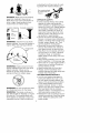
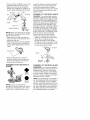
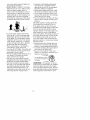
CRRFTSMRN
Operator's Manual
32cc 2-Cycle
/
Engine
17 Inch Cutting Path / .095 In. Line
GASOLINE
BRUSHWAOKER
®
Model No.
358.795020
Read
and follow all Safety Rules and Operating
DANGER:
Instructions
before first use of this product.
I_
•
For
Call answers
7 am-7
1-800-235-5878
Sears, Roebuck
530084630
to your
questions
this product:
pm,
Mon-Sat;
Sun,about
10 am-7
pm
03/15/99
and Co., Hoffman
Estates,
IL 60179 USA
Warranty Statement
Safety Rules
Assembly
Operation
Maintenance
Service & Adjustments
2
2
5
9
14
15
FULL ONE YEAR WARRANTY
BRUSHWACKER
<_
BLADED
Storage
Troubleshooting
Chart
Emissions Statement
Parts List
Spanish
Parts and Ordering
ON CRAFTSMAN
17
18
18
20
23
Back
GAS POWERED
TRIMMER.
For one year from the date of purchase, when this Craftsman Gas Powered
Brushwacker is maintained, lubricated and tuned up according to the operating
and maintenance instructions in the Operator's Manual, Sears will repair, free of
charge, any defect in materials or workmanship.
This warranty excludes the blade, nylon line, spark plug, and air filter, which are
expendable parts and become worn during normal use.
If this Brushwacker is used for commercial purposes, this warranty applies for only
90 days from the date of purchase. If this Brushwacker is used for rental purposes,
this warranty applies for only 30 days from the date of purchase. This warranty applies only while this product is in use in the United States.
WARRANTY SERVICE IS AVAILABLE BY RETURNING THE BRUSHWACKER
TO THE NEAREST SEARS SERVICE CENTER IN THE UNITED STATES.
This warranty gives you specific legal rights, and you may also have other rights
which vary from state to state.
Sears, Roebuck and Co., D/817 WA Hoffman Estates, IL 60179
DANGER:
This power tool can be
dangerous! This unit can cause serious
injury including amputation or blindness
to the operator and others. The warnings and safety instructions in this manual must be followed to provide reasonable safety and efficiency in using the
unit. The operator is responsible for following the warnings and instructions in
this manual and on the unit. Read the
entire Operator's Manual before assembling and using the unit! Restrict the use
of this unit to persons who read, understand, and follow the warnings and instructions in this manual and on the unit.
Never allow children to use this unit.
WARNING:
instructions.
in serious
Follow all warnings and
Failure to do so can result
injury.
SAFETY
NOTICE
Exposure to vibrations through prolonged use of gasoline powered hand
tools could cause blood vessel or
nerve damage in the fingers, hands,
and joints of people prone to circulation disorders or abnormal swellings.
Prolonged use in cold weather has
been linked to blood vessel damage in
otherwise healthy people. If symptoms
occur such as numbness, pain, loss of
strength, change in skin color or texture, or loss of feeling in the fingers,
hands or joints, discontinue the use of
this tool and seek medical attention.
An anti-vibration
system does not
guarantee the avoidance of these
problems. Users who operate power
tools on a continual and regular basis
must monitor closely their physical
condition and the condition of this tool.
contacting the left hand side of coasting blade with material already cut.
Stop coasting blade
by contact with cut
material
__®
DANGER:
Blade
canthrust
violently
away
frommaterial
itdoesnotcut.
Blade
thrust
cancause
amputation
of
armsorlegs.Keep
people
andanimals50feet(15meters)
away.
OPERATOR
SAFETY
• Dress properly. Always wear safety
glasses or similar eye protection
when operating, or performing maintenance on your unit. (Safety glasses
are available.) Always wear face or
dust mask if operation is dusty. Always wear heavy, long pants, long
sleeves, boots, and gloves. Do not
go barefoot or wear sandals.
• Secure hair above shoulder length.
Secure or remove loose clothing and
jewelry or clothing with loosely hanging ties, straps, tassels, etc. They
can be caught in moving parts.
• Being fully covered also helps protect you from debris and pieces of
toxic plants thrown by spinning line.
• Stay Alert. Do not operate unit when
you are tired, ill, or under influence
of alcohol, drugs, or medication.
Watch what you are doing; use common sense.
• Wear hearing protection if you use the
unit for more than 1-1/2 hours per day.
• Never start or run the engine inside a
closed room or building. Breathing
exhaust fumes can kill.
• Keep handles free of oil and fuel.
• Always use the handlebar and a
properly adjusted shoulder strap with
a blade. See "Assembly."
UNIT/MAINTENANCE
SAFETY
ALWAYS
WEAR
I THROWN
OBJECTS
Eye I
Protection I
it
Leg , I /
m m L_uaras
*
Boots
WARNING:
Trimmer line can throw
objects violently. You can be blinded or
injured. Wear eye and leg protection.
_d
WARNING:
Zone
Hazard zone for thrown
objects. Blade/Trimmer line can throw
objects violently. Others can be
blinded or injured. Keep people and
animals 50 feet (15 meters) away.
WARNING:
as a fastening
WARNING:
Do not use trimmer
• Look for and replace damaged or
loose parts before each use. Look
for and repair fuel leaks before use.
Keep unit in good working condition.
• Throw away blades that are bent,
warped, cracked, broken, or damaged in any other way. Replace trimmer head parts that are cracked,
chipped, broken, or damaged in any
other way before using the unit.
• Maintain the unit according to recommended procedures. Keep the blade
sharp. Keep the cutting line at the
proper length.
head
device for the blade.
The blade continues
to
spin after throttle is released or, engine
is turned off. The coasting blade can
throw objects or seriously cut you if accidentally touched. Stop the blade by
3
• Useonly.095"
(2.4 ram} diameter
Craftsman u_brand line. Never use
wire, rope, string, etc.
• install required shield properly before
using the unit. Use the metal shield
for all metal blade use. Use the plastic shield for all line trimmer use,
• Use only specified blade or trimmer
head; make sure it is proper_y installed and securely fastened.
• Never start engine with clutch shroud
removed. The clutch can fly off and
cause serious injury.
• Be sure blade or trimmer head stops
turning when engine idles.
• Disconnect the spark plug before
performing maintenance
(except carburetor adjustments).
• Make carburetor adjustments with
the lower end supported to prevent
the blade or trimmer line from contacting any object, Hold the unit by
hand; do not use the shoulder strap
for support.
• Keep others away when making carburetor adjustments.
• Use only recommended Craftsman
accessories and replacement parts.
• Have all maintenance and service
not explained in this manual performed by a Sears Service Center.
FUEL SAFETY
•
•
•
•
•
•
•
•
Mix and pour fuel outdoors.
Keep away from sparks or flames.
Use a container approved for fuel.
Do not smoke or allow smoking near
fuel or the unit or while using the unit.
Wipe up all fuel spills before starting
engine.
Move at least 10 feet (3 meters) away
from fueling site before starting engine.
Stop engine and allow it to cool before removing fuel cap.
Empty the fuel tank before storing
the unit. Use up fuel left in the carburetor by starting the engine and letting it run until it stops.
• Store unit and fuel in an area where
fuel vapors cannot reach sparks or
open flames from water heaters, electric motors or switches, furnaces, etc.
CUTTING SAFETY
• Inspect the area to be cut before
each use. Remove objects (rocks,
broken glass, nails, wire, string, etc.)
which can be thrown or become entangled in the blade or trimmer head.
• Keep others including children, animals, bystanders, and helpers at
least 50 feet (15 meters) away. Stop
the engine immediately if you are approached.
• Always keep engine on the righthand side of your body.
• Hold the unit firmly with both hands.
• Keep firm footing and balance. Do
not overreach.
• Keep blade or trimmer head below
waist level.
• Do not raise engine above your waist.
• Keep all parts of your body away
from blade, trimmer head, and muffler when engine is running.
• Cut from your right to your left.
• Use only for jobs explained in this
manual.
TRANSPORTING
AND STORAGE
• Stop the unit before carrying.
• Keep muffler away from your body.
• Allow engine to cool and secure unit
before storing or transporting it in a
vehicle.
• Empty the fuel tank before storing or
transporting the unit. Use up fuel left
in the carburetor by starting the engine and letting it run until it stops.
• Store unit and fuel in an area where
fuel vapors cannot reach sparks or
open flames from water heaters,
electric motors or switches, furnaces,
etc.
• Store unit so the blade or line limiter
cannot accidentally cause injury. The
unit can be hung by the tube.
• Store unit out of reach of children.
CARTON
CONTENTS
Check
carton
contents
against
thefollowing
list.
Model:
WARNING:
If received assembled,
repeat all steps to ensure your unit is
properly assembled and all fasteners
are secure.
358.795020
•
•
•
•
•
Engine
2 tube mounting screws
2 tube mounting nuts
2 handlebar screws
4 blade shield screws
•
•
•
•
1
1
1
1
cupped washer
large nut for installing blade
long hex wrench
short hex wrench
•
•
•
•
1
1
1
1
upper handlebar cover bracket
shield for use with blades
shield for use with trimmer head
trimmer head
•
•
•
•
•
1
1
1
1
1
shoulder strap with warning
weed blade
brush blade
handlebar
container of oil
ACTUAL
ASSEMBLY
SIZE
TOOLS
REQUIRED
In addition to the 2 hex wrenches provided with your unit, you will need an
adjustable wrench.
ATTACHING
NOTE:
THE
Illustrations
TUBE
within this section
will help in identifying the assembly
steps. Be sure to read each section
and review the illustrations before you
begin. Align the engine with the fuel
cap up as shown below.
NOTE: A drive shaft is located in the
center of the tube. Make sure this shaft
does not fall out of the tube. Dirt on the
shaft will significantly reduce the life of
the unit. If this shaft falls out, clean, relubricate, and re-install.
• Using a hex wrench, insert the 2 tube
mounting screws and nuts as illustrated. Keep loose at this time; you
will tighten them during a later step.
HARDWARE
Tube Mounting
Screw
Cupped Washer
Blade
Shield
Screw
Large nut for installing Blade
_
• Some units may include a plastic
cover over the end of the tube. If
your unit includes a cover, remove it
by pulling the tab.
• Pull about 1/2 inch of the drive shaft
out of the inside of the tube.
_' C"_j '_
Tube Mounting
Nut
1/2
Handlebar Screw
_Pull
Examine parts for damage.
Do not use
damaged
parts.
NOTE: If you need assistance
or find
that parts are missing or damaged,
call
] -800-235-5878.
It is normal for the fuel filter to rattle in
about Tube
inch from tube
NOTE: The square end of the drive
shaft fits inside a square hole in a shaft
inside the engine. Look inside end of
engine and you will see the square
hole in shaft. Align square end of the
drive shaft with the square hole.
the empty fuel tank.
Finding fuel or oil residue on muffler is
normal due to carburetor adjustments
and testing done by the manufacturer.
5
NOTE:
Theendofthetubehasa
groove,
orindention,
thataligns
witha
ridge,
orraised
area,
intheslotinthe
engine.
Locate
thegroove
andridge.
• Alignthegroove
inthetubewiththe
ridgeinside
opening
intheengine.
Insert
thetubeintotheopening.
"
_
Ridge
_
TRIMMER
HEAD
Groove
WEED
BLADE
• Firmly push the tube into the engine
until it will no longer go into opening.
• Now tighten the screws, using one of
the hex wrenches provided with unit.
ATTACHING
O
BRUSH
BLADE
THE HANDLEBAR
ASSEMBLY FOR USE WITH A
TRIMMER HEAD
NOTE: Unlike a bicycle, the handgrips
on the handlebar point toward the front
instead of toward the back.
• Locate decal on handlebar. Align handlebar so inner arrows point to engine.
Make sure the wire assembly is not
wrapped around the tube.
• Set handlebar on mounting bracket.
Align mounting bracket between the
outer arrows on the handlebar decal.
• Position bracket cover over the han-
HEAD
TRIMMER
dlebar. Again make sure the bracket
is between the arrows.
• Insert screws and tighten securely.
• Insert wire assembly into the groove
in the bottom of the foam grip.
Bracket
Foam Grip
Wire Assembly
CONFIGURING
Cover
NOTE: If your unit has been assembled
for brushblade use, refer to the section
"ASSEMBLY INFORMATION FOR USING
YOUR UNIT WITH A BRUSHBLADE" and
Screw
reverse the steps to remove the metal
shield and blade before you mount the
plastic shield and trimmer head.
ATTACHING
THE PLASTIC
AND TRIMMER HEAD
Handlebar
Mounting
Bracket
SHIELD
WARNING: The shield must be properly installed. The shield provides partial protection from the risk of thrown
objects to the operator and others and
is equipped with a line limiter which
cuts excess line to the proper length.
The line limiter (on underside of shield)
is sharp and can cut you.
• Remove wing nut from shield.
• Insert bracket into slot on shield.
• Pivot shield until bolt passes through
hole in bracket.
YOUR UNIT
You can configure your unit using a
cutting head or weed blade for grass
and light weeds, or a brush blade for
cutting saplings and similar size material. Go to the section for the desired
configuration and follow the instructions for assembling your unit.
• Tighten the wing nut securely.
6
• Ifyourunithasaplastic
cover
onthe
threaded
shaft,
remove
thecover.
• Make
suredustcupandretaining
washer
arepositioned
ongearbox
as
shown
before
installing
trimmer
head.
Slot
verse the steps to remove the plastic
shield and trimmer head before you
mount the metal shield and blade.
Store these parts for future use. Never
use the trimmer head with the metal
blade installed.
ASSEMBLY
Wing Nut
Gearbox
S
Shield
Dust Cup _(..___
Retaining Washer
OF THE METAL SHIELD
DANGER: The metal shield must be
properly installed on the tool anytime
the tool is used with the blade. The forward top of the metal shield helps to
reduce the occurrence of blade thrust
which can cause serious injury such
as amputation to the operator or bystanders. Failure to install the shield in
the position shown can result in serious injury to the operator. The length
of the shield must be aligned with the
length of the tube. The blade is sharp
and can cut you. Be sure to wear
gloves while working with blades.
• Place the metal shield under the
,_,_
NOTE: Make sure all parts are properly installed as illustrated before installing the trimmer head.
• Align hole in the dust cup with the
hole in the side of the gearbox by rotating the dust cup.
• Insert a hex wrench into the aligned
holes. This will keep the shaft from
turning while tightening the trimmer
head.
gearbox, and align the screw holes.
• Insert the 4 mounting screws
through the bottom of the shield.
Thread them into the gearbox. Tighten evenly and securely with one of
the hex wrenches provided.
Gearbox
Hex Wrench _
Shield
\
• While holding the hex wrench in
position, thread trimmer head onto
the shaft and tighten until secure.
• Remove the hex wrench.
ASSEMBLY
BLADE
Mounting
Screws
_
FOR USE WITH A
ASSEMBLY
I
OF THE METAL BLADE
WARNING:
Do not use any blades or
fastening hardware other than those illustrated in this manual. These items
must be Craftsman parts and installed
as shown below. Failure to use proper
parts can cause the blade to fly off and
seriously hurt you or others.
WEED
BLADE
O
NOTE: The weed blade is reversible; it
can be installed with either side facing
up. The brushblade must be installed
with the correct side facing up. The correct side will be marked on the blade. If
BRUSH
BLADE
NOTE: If your unit has been assembled for trimmer head use, refer to
the section "ATTACHING THE PLASTIC
SHIELD AND TRIMMER HEAD" and re-
you are re-installing an older blade and
the writing has worn off, install it using
the following illustration as a guide.
7
• Install the blade nut by threading
onto the shaft counterclockwise.
Top view of blade
NOTE: Make sure all parts are in place
as illustrated, and the blade is sandwiched between the dust cup and the
retaining washer. There should be no
space between the blade and the dust
cup or the retaining washer.
• Align hole in the dust cup with the
hole in the side of the gearbox by rotating the blade.
• Insert a hex wrench into aligned holes.
This will keep the shaft from turning
while tightening the blade nut.
Teeth on
blade poir
in this direction
WARNING: Do not use any blades or
fastening hardware other than the
washers and nuts illustrated. These
items must be Craftsman parts and
installed as shown. Failure to use proper
parts can cause the blade to fly off and
seriously hurt you or others.
Hex Wrench _
• If your unit has a plastic cover on the
threaded shaft, remove the cover.
• Remove the retaining washer from
the gearbox; leave the dust cup on
the gearbox.
Retaining
Washer _
• Tighten blade nut firmly with a wrench
while holding hex wrench in position.
• Remove the hex wrench.
• Turn blade by hand. If blade binds
against the shield or appears to be
uneven, the blade is not centered,
and you must reinstall the blade.
NOTE: To remove blade, insert hex
wrench into aligned holes. Unthread
nut and remove parts. Be sure to store
parts and instructions for future use.
@
• Install the blade between the dust
cup and retaining washer as shown
in the following illustration. Make
sure the raised part of the retaining
washer is facing the gearbox, and
the raised area fits into the hole in
the center of the blade
Clamp
ASSEMBLY
_"
it
OF SHOULDER
STRAP
WARNING: Adjust shoulder strap and
handlebar before starting the engine.
• Rotate clamp to the upright position;
tighten T-handle securely.
• Try on shoulder strap and adjust for
fit and balance before starting engine
or beginning a cutting operation.
• Insert your right arm and head
through the shoulder strap and allow
it to rest on your left shoulder. Make
sure the danger sign is on your back
and the hook is to the right side of
your waist.
• Adjust the strap, allowing the hook to
be about 6 inches below the waist.
• Fasten the strap hook to the clamp.
Lift the tool to the operating position.
NOTE: Unclip the shoulder strap from
the clamp before starting the unit.
Blade
Retaining/_
Washer
Cupped//4______._
Washer
Nut '_
• Place the cupped washer onto the
shaft. Make sure the cupped side of
the washer is toward the blade as
shown.
8
KNOW
YOURBRUSHWACKER
READ THIS OPERATOR'S MANUAL AND SAFETY RULES BEFORE OPERATING YOUR
UNIT. Compare the illustrations with your unit to familiarize yourself with the location of various controls and adjustments. Save this manual for future reference.
Control Handle
j
_
Starter
j_qJ=_
Handle _,
Choke
Primer
/' <.-_ " :b\_-,,. Lever
....
_<,'%__
Bulb
Muffler
Switch
One®
ON/STOP SWITCH
The On/Stop switch is located on the
control handle and is used to stop the
engine. Push the switch to the stop
position to stop the unit.
THROTTLE LOCKOUT
er pulls on the starter rope. Activate
the primer bulb by pressing it and allowing it to return to its original form.
CHOKE
The choke helps to supply fuel to the
carburetor during starting. This allows
you to start a cold engine. Activate the
choke by moving the choke lever to
the Full position. After the engine has
started, move the choke to the Off
position.
The Throttle Lockout prevents the
throttle trigger from being depressed.
PRIMER BULB
The primer bulb removes air from the
fuel lines and fills them with fuel. This
allows you to start the engine with fewBEFORE
STARTING
ENGINE
IMPORTANT
WARNING:
Be sure to read the fuel
information in the safety rules before
you begin. If you do not understand
the safety rules, do not attempt to fuel
your unit. Call 1-800-235-5878.
FUELING
Experience indicates that alcohol
blended fuels (called gasohol or using
ethanol or methanol) can attract moisture which leads to separation and
formation of acids during storage.
Acidic gas can damage the fuel system of an engine while in storage.
ENGINE
This engine is certified to operate on
unleaded gasoline. Before operation,
gasoline must be mixed with a good
quality 2-cycle air-cooled engine oil.
We recommend Craftsman brand oil.
To avoid engine problems, empty the
fuel system before storage for 30 days
or longer. Drain the gas tank, start the
engine and let it run until the fuel lines
and carburetor are empty. Use fresh
fuel next season.
Mix gasoline and oil at a ratio of 40:1
(A 40:1 ratio is obtained by mixing 3.2
ounces of oil with 1 gallon of unleaded
gasoline). DO NOT USE automotive oil
or boat oil. These oils will cause
engine damage. When mixing fuel,
follow instructions printed on container.
Never use engine or carburetor cleaner products in the fuel tank or permanent damage may occur.
See the STORAGE section for additional information.
9
STOPPING
YOUR
ENGINE
Starter _,.
Handle "_
• Move the On/Stop switch to the
STOP position.
• If engine does not stop, move choke
to the Full Choke position.
on/Stop
Switch
off
On
Throttte Trigger
STARTING
Choke
YOUR
ENGINE
NOTE: A special feature called tile
"Throttle Lock" holds the throttle trigger
in the depressed position for you during starting.
• Lock the throttle trigger into the starting postion by first pressing the lockout lever on the top of the control
handle. While the lockout lever is depressed, squeeze and hold the
throttle trigger.
Lock Button
_/
Throttle Trigger
Lockout Lever
_C__'_Z_,_
• Before releasing
the throttle trigger,
press the lock button. While this button is still depressed release the
throttle trigger.
NOTE: This should allow the throttle
trigger to remain in the depressed
position for starting. You may want to
practice this a few times before you
first start the unit.
• DO NOT squeeze throttle trigger during starting; otherwise, it will be necessary to reset the throttle lock.
COLD ENGINE OR WARM ENGINE
AFTER RUNNING OUT OF FUEL
WARNING:
The blade or trimmer
head will turn while starting the engine.
Avoid any contact with the muffler. A
hot muffler can cause serious burns.
• Rest engine and shield on ground,
supporting trimmer head off ground.
• Move the switch to the on position.
• Slowly press the primer bulb 6 times.
• Move choke to Full Choke position.
Primer Bulb
• Set the throttle trigger in the starting
postion using the throttle lock feature. Keep throttle trigger in the starting position until the engine runs
smoothly.
• Pull starter rope sharply until engine
attempts to run or 5 times.
• Move choke lever to Half Choke.
• Pull starter rope sharply until engine
runs, but no more than 6 pulls.
NOTE:
If the engine has not started
after 6 pulls (at half choke), check to
make sure the choke lever is in the
proper position. Then, move the choke
to the Full Choke position and press
the primer bulb 6 times; pull the starter
rope 2 more times. Move the choke
lever to Half Choke and pull the starter
rope until the engine runs, but no more
than 6 more pulls. If the engine still has
not started, it is probably flooded. Proceed to "Starting a Flooded Engine."
• Allow the engine to run 10 seconds,
then move choke lever to Off Choke.
Let the engine run 30 more seconds
at Off Choke before releasing the
throttle lock. Release throttle lock by
squeezing and releasing the trigger.
STARTING
A WARM ENGINE
• Move the switch to the on position,
and choke to Half Choke position.
• Set the throttle trigger in the starting
postion using the throttle lock feature. Keep throttle trigger in the starting position until the engine runs
smoothly.
• Pull starter rope sharply until engine
runs, but no more than 5 pulls.
• Allow engine to run 15 seconds, then
move the choke lever to Off Choke.
NOTE: If engine has not started, pull
starter rope 5 more pulls. If engine still
does not run, it is probably flooded.
10
DIFFICULT STARTING OR
STARTING A FLOODED ENGINE
Flooded engines can be started by
moving choke lever to Off Choke; then,
pull the rope to clear the engine of excess fuel. This could require pulling the
starter handle many times depending
on how badly the unit is flooded.
If the unit still doesn't start, refer to
TROUBLESHOOTING
chart or call
1-800-235-5878.
OPERATING
POSITION
Control Handle
in Right Hand
Position
Operating
Clip shoulder strap onto clamp and
stand to operating position.
• Arms extended with hands holding
the handlebar grip.
• Right hand holding control handle,
with fingers on throttle trigger.
• Engine below waist level.
• Shoulder strap pad centered on left
shoulder.
• Danger sign centered on your back.
• Full weight of tool on left shoulder.
• Without operator bending over, the
blade or semi-automatic
head is near
and parallel to the ground and easily
contacts material to be cut.
OPERATING
INSTRUCTIONS
FOR USE WITH TRIMMER
HEAD
Bring the engine to cutting speed before entering the material to be cut.
Do not run engine at a higher speed
than necessary. The cutting line will cut
efficiently when engine is run at less
than full throttle. At lower speeds, there
is less engine noise and vibration. The
cutting line will last longer and will be
less likely to "weld" onto the spool.
If the trimmer head does not turn when
the engine is in operation, make sure
the drive shaft housing is properly
seated in engine shroud.
Always release the throttle trigger and
allow the engine to return to idle speed
when not cutting.
To stop engine:
• Release the throttle trigger.
• Move the On/Stop switch to the
STOP position.
• If engine does not stop, move choke
to the Full Choke position.
ADVANCING
THE TRIMMER
LINE
The trimmer line will advance approximately 2 in. (5 cm) each time bottom of
trimmer head is tapped on the ground
with the engine running at full throttle.
The most efficient line length is the
maximum length allowed by line limiter.
Always keep the shield in place when
the tool is being operated.
To Advance Line:
• Operate the engine at full throttle.
• Hold the trimmer head parallel to and
above the grassy area.
• Tap bottom of trimmer head lightly on
ground one time. Approximately 2 in.
(5 cm) of line will be advanced with
each tap. The line limiter on the shield
will cut line to the correct length.
"_¥ _C__:<"
.,he
Umiter
Always tap the trimmer head on a
grassy area. Tapping on surfaces such
as concrete or asphalt can cause excessive wear to the trimmer head.
If line is worn down to 2 in. (5 cm) or
less, more than one tap will be required
to obtain the most efficient line length.
WARNING:
Use only .095" (2.4 mm)
diameter line. Other sizes of line will
not advance properly and can cause
serious injury. Do not use other materials such as wire, string, rope, etc. Wire
can break off during cutting and become a dangerous missile that can
cause serious injury.
CUTTING
METHODS
WARNING:
Use minimum speed and
do not crowd the line when cutting
around hard objects (rock, gravel,
fence posts, etc.), which can damage
the trimmer head, become entangled
in the line, or be thrown causing a serious hazard.
11
• Thetipofthelinedoes
thecutting.
Youwillachieve
bestperformance
and
minimum
linewear
bynotcrowding
lineintothecutting
area.
Theright
and
wrong
ways
areshown
below.
TipoftheLine I Line
Crowded
into
Does
TheCutting
Work
Area
Right :"_:_'-"_,1
Wrong = "
posts, monuments, etc. This technique
increases line wear.
Scalping
MOWING
'"
• The line will easily remove grass and
weeds from around walls, fences,
trees and flower beds, but it also can
cut the tender bark of trees or shrubs
and scar fences. To help avoid damage especially to delicate vegetation
or trees with tender bark, shorten line
to 4-5 in. (10-13 cm) and use at less
than full throttle.
• For trimming or scalping, use less
than full throttle to increase line life
and decrease head wear, especially:
• During light duty cutting.
• Near objects around which the line
can wrap such as small posts,
trees or fence wire.
• For mowing or sweeping, use full
throttle for a good clean job.
WARNING:
Always wear eye protection. Never lean over the trimmer head.
Rocks or debris can ricochet or be
thrown into eyes and face and cause
blindness or other serious injury.
TRIMMING - Hold the bottom of the
trimmer head about 3 in. (8 cm) above
the ground and at an angle. Allow only
the tip of the line to make contact. Do
not force trimmer line into work area.
Trimming
il >
- Your trimmer is ideal for
mowing in places conventional lawn
mowers cannot reach. In the mowing
position, keep line parallel to ground.
Avoid pressing head into ground as this
can scalp ground and damage tool.
Mowing
SWEEPING - The fanning action of
rotating line can be used for a quick
and easy clean up. Keep line parallel
to and above the surfaces being swept
and move the tool from side to side.
_/-
_.z
OPERATING
INSTRUCTIONS
FOR USE WITH A BLADE
• Blade Thrust is a reaction that only occurs when using a bladed unit. This
reaction can cause serious injury such
as amputation. Carefully study this
section. It is important that you understand what causes blade thrust, how
you can reduce the chance of its occurring, and how you can remain in
control of unit if blade thrust occurs.
• WHAT CAUSES BLADE THRUST
Blade Thrust can occur when spinning
blade contacts an object that it does
not cut. This contact causes blade to
3 in. (8 cm)
;'_"_.":'_"_=--,_ 2 2,
Above Ground _i_l_._,_"
_"
stop for an instant and then suddenly
move or "thrust" away from object that
was hit. The "thrusting" reaction can
be violent enough to cause operator to
be propelled in any direction and lose
control of unit. The uncontrolled unit
SCALPING - The scalping technique
removes unwanted vegetation. Hold bottom of trimmer head about 3 in. (8 cm)
above ground and at an angle. Allow tip
of line to strike the ground around trees,
12
cancause
serious
injury
ifblade
con- • Keep
feetcomfortably
spread
apart
tacts
operator
orothers.
andbraced
forapossible
sudden,
• WHEN
BLADE
THRUST
OCCURS. rapid
thrust
ofunit.Donotoverreach.
Blade
thrust
canoccur
without
warn- Keep
firmfooting
andbalance.
ingiftheblade
snags,
stalls,
or
• Keep
blade
below
waistlevel.
Itwill
beeasier
tomaintain
control
ofunit.
binds.
Thisismore
likelytooccur
in
areas
where
itisdifficult
toseethe
• Donotraise
theengine
above
your
material
being
cut.Byusing
theunit
waistastheblade
cancome
dangerproperly,
theoccurrence
ofblade
ously
close
toyourbody.
thrust
willbereduced
andtheopera- • Donotswing
theunitwithsuchforce
torwillbelesslikely
tolosecontrol. thatyouareindanger
oflosing
your
balance.
Bring
theengine
tocutting
speed
beforeentering
thematerial
tobecut.
Iftheblade
doesnotturnwhen
you
squeeze
thethrottle
trigger,
make
sure
thetubeisfullyinserted
intoengine.
Always
release
thethrottle
trigger
and
allow
engine
toreturn
toidlespeed
• Cutonlygrass,
weeds,
andwoody whennotcutting.
Theblade
should
not
brush
upto1/2inchindiameter
with turnwhile
theengine
isrunning
atidle.
weed
blade,
andupto2inches
with Iftheblade
turnsatidle,donotuse
brush
blade.
Donotletblade
contact yourunit.Refer
totheCarburetor
admaterial
itcannot
cutsuch
asstumps, justment
section
orcontact
yourSears
Center.
rocks,
fences,
metal,
etc.,orclusters Service
ofhard,
woody
brush
witha diameter • Maintain
goodfirmfooting
whileusgreater
thanthatrecommended. ingtheunit.Dothisbyplanting
feet
• Useasharp
blade.
Adullblade
is
firmlyinacomfortable
apart
position.
more
likelytosnagandthrust.
• Cutwhileswinging
theupper
partof
• Outonlyatfullthrottle.
Theblade
will yourbody
fromrighttoleft.
havemaximum
cutting
power
andis • Asyoumove
forward
tothenext
lesslikelytobindorstall.
areatocut,besuretomaintain
your
• "Feed"
theblade
deliberately
andnot balance,
andfooting.
toorapidly.
Theblade
canthrust
10o'clock
_
away
ifitisfedtoorapidly.
Cut
using
the
8o'clock
_
_'l_l_"}"
_
• Cutonlyfromyourright
toyourleft.
to10o'clock
position
of._,,y ]1 _[
Swinging
unitinthesame
direction
as
the blade
8 o,clock _._ _
blade
spinincreases
cutting
action.
WARNING:
The operator or others
• Usetheshoulder
strapandkeep
a
firmgripontheunitwithbothhands. must not try to clear away cut material
Aproperly
adjusted
shoulder
strap with the engine running or the blade
willsupport
theweight
oftheunit,
turning to avoid serious injury. Stop enfreeing
yourarmsandhands
tocon- gine and blade before removing matetrolandguide
thecutting
motion.
rials wrapped around blade or tube.
13
MAINTENANCE
SCHEDULE
CARE & MAINTENANCE
Check for Loose fasteners
TASK
Before each use
Check for damaged or worn parts
Clean unit and labels
Before each use
Clean air filter
Every 5 hours of operation
After each use
Inspect and clean spark arrestor
Every 25 hours of operation
Replace
Yearly
spark plug
GENERALRECOMMENDATIONS
The warranty on this unit does not cover items that have been subjected to
operator abuse or negligence. To receive full value from the warranty, the
operator must maintain unit as instructed in this manual. Various adjustments
will need to be made periodically to
properly maintain your unit.
CHECK
FOR
FASTENERS
•
•
•
•
•
WHEN TO PERFORM
and parts
LOOSE
AND PARTS
A dirty air filter decreases engine performance and increases fuel consumption and harmful emissions. Always
clean after every 5 hours of operation.
• Clean cover area around it to keep dirt
and debris from falling into carburetor
chamber when cover is removed.
•
•
•
•
Spark Plug Boot
Air Filter
Housing Screws
Assist Handle Screws
Shield
CHECK
WORN
FOR DAMAGED
PARTS
Remove parts as illustrated.
Wash the filter in soap and water.
Allow filter to dry=
Replace parts, making sure the filter
is seated completely.
Lws
OR
Refer replacement of damaged/worn
parts to your Sears Service Center.
• On/Stop Switch - Ensure On/Stop
switch functions properly. Move switch
to "Stop." Make sure engine stops;
then restart engine and continue.
• Fuel Tank - Discontinue use if fuel
view of
Air Filter
Cover
Air
Filter
JBack
tank shows signs of damage or leaks.
• Shield - Discontinue use of unit if
shield is damaged.
CLEAN
UNIT
& LABELS
• Clean the unit using a damp cloth
with a mild detergent.
• Wipe off unit with a clean dry cloth.
CLEAN
AIR
FILTER
Do not clean filter in gasoline or other
flammable solvent to avoid creating a
fire hazard or producing harmful evaporative emissions.
INSPECT
ARRESTOR
AND
CLEAN
SPARK
(if equipped)
As tile unit is used, carbon deposits
build up on the muffler and spark
arrestor screen, and must be removed
to avoid creating a fire hazard or affecting engine performance.
Remove the spark arrestor screen
from the muffler and clean. Replace
spark arrestor screen if breaks occur.
14
REPLACE
SPARKPLUG
Replace the spark plug each year to
ensure the engine starts easier and
runs better. Set spark plug gap at
.025 in. Ignition timing is fixed and
nonadjustable.
• Twist, then pull off spark plug boot.
REPLACING
THE
LINE
WARNING:
Trimmer head parts that
are chipped, cracked, broken, or damaged in any other way can fly apart and
cause serious injury. Do not use. Replace damaged parts before using unit.
• Press the tab on the side of the trim-
• Remove spark plug from cylinder
and discard.
• Replace with Champion CJ-8Y spark
plug and tighten with a 3/4 in. socket
wrench (10-12 ft.-Ibs).
• Reinstall the spark plug boot.
• With your finger between the lines,
wrap the lines evenly and and firmly
around the spool in the direction of
the arrow on the spool
• Position the lines in the guide slots.
mer head and twist the lock ring.
• Remove the lock ring and tap button.
Tab
L_J
//" "-_7._
Lock Ring
Tap Button
• Pull the spool out of the trimmer
head. Remove any remaining line.
• Clean dirt and debris from all parts.
Replace spool if it is worn or damaged.
• Replace with a pre-wound spool, or
replace line using two 20 foot lengths
of .095 inch (2.4 mm) diameter
Craftsman _R_
line.
• Insertthe ends ofthe lines through exit
holes in the sides ofthe trimmer head.
• Place the spool in the trimmer head.
• Make sure the lines are not caught
between the rim of the spool and the
wall of the trimmer head.
• Reinstall the tap button and lock ring
onto the trimmer head.
• Align the lock ring over the catches
on the trimmer head. Push the ring
down and turn until the catches lock
into place.
• When installing new line on an existing spool, insert 1/16" of the end of
each line into the anchoring holes in
the bed of the spool.
__))
Catch
_ch
Anchoring
• Make sure the lock ring is securelyfastened by pulling on it and twisting in
both directions.
WARNING:
All catches must be fastened and the lock tab latched in the
Arrow
lock ring. If installed incorrectly, the
lock ring can fly off and become a dangerous missile.
• Pull line extending
15
from trimmer head.
CARBURETOR
ADJUSTMENT
WARNING:
The trimmer head or
blade will be spinning during most of this
procedure. Wear protective equipment
and observe all safety precautions. After
making mixture adjustments, recheck
idle speed.
Carburetor adjustment is critical and if
done improperly can permanently
damage the engine as well as the carburetor. If you require further assistance or are unsure about performing
this procedure, call our customer assistance help line at 1-800-235-5878.
Old fuel, a dirty air filter, a dirty fuel filter, or flooding may give the impression of an improperly adjusted carburetor. Check these conditions before
adjusting
the carburetor.
The carburetor has been carefully set
at the factory. Adjustments may be
necessary if you notice any of the following conditions:
• Engine will not idle. See "Idle Speed"
under adjusting procedure.
• Engine dies or hesitates instead of
accelerating. See "Acceleration
Check" under adjusting procedure.
• Loss of cutting power. See "Mixture
Adjustment" under adjusting
procedure.
There are three adjustment screws on
the carburetor. The low speed adjustment screw is marked with the letter L,
and the high speed adjustment screw
is marked with the letter H. The third
screw is the idle adjustment screw.
L Screw
Idle Adjustment
CARBURETOR
PRESETS
When making carburetor preset adjustments, do not force plastic limiter caps
beyond stops or damage will occur.
If carburetor presets are not needed,
proceed to "Adjusting Procedure, Idle
Speed."
To adjust presets:
• Turn both mixture screws
counter-
clockwise to the midpoint between
the limiter cap stops.
• Turn the idle speed screw clockwise
until it stops. Now turn counterclockwise 4-1/2 turns.
• Start motor, cut grass for 3 minutes,
and proceed to the adjustment section. If engine does not start,
refer to troubleshooting
chart or call
1-800-235-5878.
• If engine performance is acceptable
at the preset positions, no further adjustment is necessary.
ADJUSTING
Idle Speed
PROCEDURE
Adjustment
Allow engine to idle. Adjust speed until
engine runs without stalling.
• Allow engine to idle. Be sure trimmer
line is extended to the maximum
length allowed by the line limiter.
• Adjust idle speed screw until engine
continues to run without stalling.
• Turn the screw clockwise to increase engine speed if the engine
stalls or dies.
• Turn screw counterclockwise
to
slow engine down.
• Follow instructions in "Acceleration
Check."
• No further adjustments are necessary
if performance is satisfactory and trimmer head does not turn at idle speed.
Low
Speed
Adjustment
"L"
When making carburetor adjustments,
do not force plastic limiter caps beyond
stops or damage will occur.
• Allow the engine to idle.
• Turn screw "L" slowly clockwise until
the speed begins to drop. Note the
position of the screw. Do not attempt
to adjust beyond the stops as damage can occur.
• Slowly turn the screw counterclockwise until the speed increases and
then begins to drop.
• Adjust the screw to the midpoint between the two positions.
• Check the acceleration by following
the steps outlined under ACCELERATION CHECK. The trimmer head must
not turn at idle speed.
16
High Speed Adjustment
"H"
CAUTION:
Do not operate engine at
full speed for prolonged periods while
making mixture adjustments as damage to the engine can occur.
When making carburetor adjustments,
do not force plastic limiter caps beyond
stops or damage will occur.
• Support lower end of the unit so that
it is off the ground and will not make
contact with any objects. Be sure the
trimmer line is extended to maximum
length allowed by the line limiter.
• Start the engine and allow to idle.
• Squeeze the throttle trigger fully.
• Keep unit running at full speed; turn
screw "H" very slowly clockwise until
the speed begins to slow down.
• Do not let go of the throttle trigger,
and turn screw counterclockwise
until the engine begins to run roughly.
• Still holding the throttle trigger, turn
the screw slowly a small amount until
Prepare unit for storage at end of season or if it will not be used for 30 days
or more.
WARNING:
• Allow engine to cool, and secure the
unit before storing or transporting.
• Store unit and fuel in a well ventilated area where fuel vapors cannot
reach sparks or open flames from
water heaters, electric motors or
switches, furnaces, etc.
• Store unit with all guards in place.
Position unit so that any sharp object
cannot accidentally cause injury.
• Store unit and fuel well out of the
reach of children.
EXTERNAL
SURFACES
If your unit is to be stored for a period
of time, clean it thoroughly before storage. Store in a clean dry area.
• Lightly oil external metal surfaces.
FUEL SYSTEM
Under Fueling Engine in the Operating
Section of this manual, see message
labeled IMPORTANT regarding the use
of gasohol in your engine.
Fuel stabilizer is an acceptable alternative in minimizing the formation of
fuel gum deposits during storage. Add
the engine begins to run smoothly.
• Check the acceleration by following
the steps outlined under ACCELERATION CHECK. The trimmer head must
not turn at idle speed.
Acceleration
Check
• Allow engine to idle. Be sure trimmer
line is extended to the maximum
length allowed by the line limiter.
• Squeeze trigger fully: If the engine
does not accelerate smoothly, turn
screw "L" counterclockwise
a small
amount (no more than the width of
the slot in the adjusting screw). Do
not attempt to adjust screws beyond
the stops as damage can occur.
• Repeat above steps until smooth acceleration is obtained. Do not attempt to adjust the screw beyond
stops as damage can occur.
IGNITION
the
TIMING
Ignition timing is fixed, non-adjustable.
stabilizer to the gasoline in the fuel
tank or fuel storage container. Follow
the mix instructions found on stabilizer
container. Run engine at least 5 minutes after adding stabilizer.
CRAFTSMAN 40:1,2-cycle engine oil (air
cooled) is already blended with fuel stabilizer. If you do not use this oil, you can
add fuel stabilizer to your fuel tank.
ENGINE
• Remove spark plug and pour I teaspoon of 40:1,2-cycle
engine oil (air
cooled) through the spark plug opening. Slowly pull the starter rope 8 to
10 times to distribute oil.
• Replace spark plug with new one of
recommended type and heat range.
• Clean air filter.
• Check entire unit for loose screws,
nuts, and bolts. Replace any damaged, broken, or worn parts.
• At the beginning of the next season,
use only fresh fuel having the proper
gasoline to oil ratio.
OTHER
• Do not store gasoline from one season to another.
• Replace your gasoline can if it starts
to rust.
17
TROUBLESHOOTING
CHART
TROUBLE CAUSE
Engine will not
start.
•
•
•
•
• Compression
Engine will not
idle properly.
REMEDY
Engine flooded.
Fuel tank empty.
Spark plug not firing.
Fuel not reaching
carburetor.
•
•
•
•
See "Starting Instructions."
Fill tank with correct fuel mixture.
Install new spark plug.
Check for dirty fuel filter; replace.
Check for kinked or split fuel line;
repair or replace.
• Contact Sears Service.
low.
• Idle speed set too low=
• Idle speed set too high.
• Carburetor requires
adjustment.
• Crankshaft seals worn.
• Compression
low.
Engine will not
accelerate,
lacks power,
or dies under
a load.
Engine smokes
excessively.
• Air filter dirty.
• Spark plug fouled.
• Carburetor requires
adjustment.
• Carbon build up.
• Compression
low.
• Choke partially on.
• Fuel mixture incorrect.
• Air filter dirty.
• Carburetor requires
adjustment.
Engine runs hot.
• Fuel mixture incorrect.
• Spark plug incorrect.
• Carburetor requires
adjustment
• Carbon build up=
YOUR WARRANTY RIGHTS AND
OBLIGATIONS:
The U. S. Environmental Protection Agency/California
Air Resources Board and SEARS,
ROEBUCK AND CO., USA are
pleased to explain the emissions control system warranty on your lawn and
garden equipment engine. All new utility and lawn and garden equipment
engines must be designed, built, and
equipped to meet the stringent antismog standards. SEARS must warrant
the emission control system on your
lawn and garden equipment engine for
• Adjust idle speed screw
clockwise to increase speed.
• Adjust idle speed screw counterclockwise to reduce speed.
• See "Carburetor Adjustments."
• Contact Sears Service.
• Contact Sears Service.
• Clean or replace air filter.
• Clean or replace spark plug
and re-gap.
• See "Carburetor Adjustments."
• Contact Sears Service.
• Contact Sears Service.
• Adjust choke.
• Empty fuel tank and refill with
correct fuel mixture.
• Clean or replace air filter.
• See "Carburetor Adjustments."
• See "Fueling Your Unit."
• Replace with correct spark plug.
• See "Carburetor Adjustments."
• Contact Sears Service.
the periods of time listed below provided there has been no abuse, neglect, or improper maintenance of your
lawn and garden equipment engine.
Your emission control system includes
parts such as the carburetor and the
ignition system. Where a warrantable
condition exits, SEARS will repair your
lawn and garden equipment engine at
no cost to you. Expenses covered under warranty include diagnosis, parts
and labor. MANUFACTURER'S
WARRANTY COVERAGE:
If any emissions
related part on your engine (as listed
18
under
Emissions
Control
Warranty
Parts
List)isdefective
oradefect
in
thematerials
orworkmanship
ofthe
engine
causes
thefailure
ofsuchan
emission
related
part,thepartwillbe
repaired
orreplaced
bySEARS.
OWNER'S
WARRANTY
RESPONSIBILITIES: As tile lawn and garden
equipment engine owner, you are responsible for the performance of the
required maintenance listed in your
Owner's Manual. SEARS recommends
that you retain all receipts covering
maintenance
on your lawn and garden
equipment engine, but SEARS cannot
deny warranty solely for the lack of receipts or for your failure to ensure the
performance of all scheduled maintenance.
As the lawn and garden
equipment engine owner, you should
be aware that SEARS may deny you
warranty coverage if your lawn and
garden equipment engine or a part of it
has failed due to abuse, neglect, improper maintenance, unapproved
modifications, or the use of parts not
made or approved by the original
equipment manufacturer.
You are responsible for presenting your lawn and
garden equipment engine to a SEARS
authorized repair center as soon as a
problem exists. Warranty repairs
should be completed in a reasonable
amount of time, not to exceed 30 days.
If you have any questions regarding
your warranty rights and responsibilities, you should contact your nearest
authorized service center or call
SEARS at 1-800-473-7247
WARRANTY COMMENCEMENT
DATE: The
warranty period begins on the date the
lawn and garden equipment engine is
purchased.
LENGTH OF COVERAGE: This warranty shall be for a period of two years from the initial date of
purchase. WHAT IS COVERED: REPAIR OR REPLACEMENT
OF
PARTS. Repair or replacement of any
warranted part will be performed at no
charge to the owner at an approved
SEARS servicing center. If you have
any questions regarding your warranty
rights and responsibilities,
you should
contact your nearest authorized service center or call SEARS at
1-800-473-7247.
WARRANTY
PE-
RIOD: Any warranted part which is not
scheduled for replacement as required
maintenance, or which is scheduled
only for regular inspection to the effect
of "repair or replace as necessary"
shall be warranted for 2 years. Any
warranted part which is scheduled for
replacement as required maintenance
shall be warranted for the period of
time up to the first scheduled replacement point for that part. DIAGNOSIS:
The owner shall not be charged for
diagnostic labor which leads to the determination that a warranted part is defective if the diagnostic work is performed at an approved SEARS
servicing center. CONSEQUENTIAL
DAMAGES: SEARS may be liable for
damages to other engine components
caused by the failure of a warranted
part still under warranty. WHAT IS
NOT COVERED: All failures caused
by abuse, neglect, or improper maintenance are not covered. ADD-ON OR
MODIFIED PARTS: The use of add-on
or modified parts can be grounds for disallowing a warranty claim. SEARS is not
liable to cover failures of warranted
parts caused by the use of add-on or
modified parts. HOW TO FILE A
CLAIM: If you have any questions regarding your warranty rights and responsibilities, you should contact your
nearest authorized service center or
call SEARS at 1-800-473-7247.
WHERE TO GET WARRANTY SERVICE: Warranty services or repairs shall
be provided at all SEARS service centers. call: 1-800-473-7247.
MAINTENANCE, REPLACEMENT AND REPAIR OF EMISSION RELATED
PARTS: Any SEARS approved replacement part used in the performance of any warranty maintenance
or repair on emission related parts will
be provided without charge to the owner if the part is under warranty. EMISSION CONTROL WARRANTY
PARTS LIST: Carburetor, Ignition System: Spark Plug (covered up to maintenance schedule), Ignition Module.
MAINTENANCE
STATEMENT: The
owner is responsible for the performance of all required maintenance as
defined in the owner's manual.
19
For in-home
major brand repair service:
Call 24 hours a day, 7 days a week
1-800-4-MY-HOME (1-800-469-4663)
TM
Para pedir servicio
de reparacidn
a domicilio
-- 1-800-676-5811
In Canada for all your service and parts needs call
Au Canada pour tout le service ou les pieces -- 1-800-665-4455
For the repair or replacement
parts you need:
Call 6 am - 11 pm CST, 7 days a week
PartsDirect
1-800-366-PART
Para ordenar
TM
(1-800-366-7278)
pieza8 con entrega
a domicilio
-- 1-800-659-7084
For the location of a Sears Parts and Repair Center in your area:
Call 24 hours a day, 7 days a week
1-800-488-1222
For information
on purchasing
a Sears Maintenance
or to inquire about an existing Agreement:
Call 9 am - 5 pm, Monday - Saturday
1-800-827-6655
SEARS
HomeCentrar °
20
Agreement