1
IMPORTANT:
THESE INSTRUCTIONS ARE TO REMAIN
WITH THE HOMEOWNER
FOR YOUR SAFETY
WARNING: If the information in this manual
is not followed exactly, a fire or explosion
may result causing property damage,
personal injury or loss of life.
-- Do not store or use gasoline or other
flammable vapors and liquids in the vicinity
of this or any other appliance.
TC42
INSTALLATION
AND OPERATING
INSTRUCTIONS
-- WHAT TO DO IF YOU SMELL GAS
• Do not try to light any appliance.
• Do not touch any electrical switch; do
not use any phone in your building.
• Immediately call your gas supplier
from a neighbour’s phone. Follow
the gas supplier’s instructions.
• If you cannot reach your gas supplier,
call the fire department.
-- Installation and service must be
performed by a qualified installer, service
agency or the gas supplier.
This appliance may be installed in an aftermarket permanently located, manufactured
home (USA only) or mobile home, where
not prohibited by local codes.
This appliance is only for use with the
type of gas indicated on the rating plate.
This appliance is not convertible for use
with other gases, unless a certified kit is
used.
050207-40
MODEL TC42
SERIES C
MODULAR DIRECT VENT
FIREPLACE
TC42.CE
5056.426.C
Contents
CAUTION............................................................................................................... 3
SAFETY ................................................................................................................ 3
MASSACHUSETTS RULES AND REGULATIONS .............................................. 4
MANTEL CLEARANCES ...................................................................................... 5
LOCATING THE FIREPLACE ............................................................................... 6
INSTALLATION REQUIREMENTS ....................................................................... 6
TOP STANDOFFS ................................................................................................. 6
FRAMING AND FINISHING .................................................................................. 7
MAESTRO CONTROL SYSTEM ........................................................................... 9
CONVERSION LP ............................................................................................... 11
HEARTH EXTENSION ........................................................................................ 18
VENTING ............................................................................................................. 18
WALL TERMINATION VENTING ........................................................................ 18
ROOF TERMINATION VENTING ........................................................................ 23
VENT TERMINAL CLEARANCE ........................................................................ 25
VENT PIPE SEALANT ........................................................................................ 26
VENT RESTRICTOR ADJUSTMENT.................................................................. 27
MANUFACTURED (MOBILE) HOME ................................................................. 27
GAS SUPPLY ...................................................................................................... 28
WINDOW FRAME REMOVAL ............................................................................. 28
BRICK PANELS INSTALLATION ....................................................................... 29
LIGHTING INSTRUCTIONS ............................................................................... 30
FIRST FIRE ......................................................................................................... 30
MAINTENANCE .................................................................................................. 31
APPENDIX A ....................................................................................................... 31
REPLACEMENT PARTS .............................................................................. 32
REPLACEMENT PARTS - MAESTRO CONCEALED VALVE ..................... 33
POWER VENT WIRING DIAGRAM .............................................................. 34
ROOF TERMINATION KIT ............................................................................ 35
WALL TERMINATION KIT ............................................................................ 35
WALL SHIELD/CEILING FIRESTOP THIMBLE ........................................... 35
VENT PIPE DIMENSIONS............................................................................ 36
VENT OFFSET CHART ................................................................................ 37
SAFETY LABEL LOCATION ........................................................................ 39
page 2
TC42.CE
050207-40
CAUTION
SAFETY
FOR YOUR SAFETY - Do not install or operate your Town
and Country fireplace without first reading and understanding
this manual. Any installation or operational deviation from the
following instructions voids the Town and Country FireplacesTM
Warranty and may prove hazardous.
Due to high temperatures, this gas appliance should
be located out of traffic and away from furniture and
draperies.
Children and adults should be alerted to the hazards of
high surface temperatures and should stay away to avoid
burns or clothing ignition.
This appliance and its individual shutoff valve must be disconnected from gas supply piping system during any pressure
testing of that system at test pressures in excess of 1/2 psig
(3.5 kPa).
Young children should be carefully supervised when they
are in the same room as the appliance.
Clothing or other flammable material should not be placed
on or near the appliance.
This appliance must be isolated from the gas supply piping
system by closing its individual manual shutoff valve during
any pressure testing of the gas supply piping system at test
pressures equal to or less than 1/2 psig (3.5 kPa).
Any grill, panel or door removed for servicing the unit
must be replaced prior to operating. Failure to do so may
create a hazardous condition.
Note: When lit for the first time, the appliance will emit a slight
odour for a couple of hours. This is due to the curing of paints,
sealants and lubricants used in the manufacturing process.This
condition is temporary. Open doors and windows to ventilate
area. Smoke and fumes caused by the curing process may
cause discomfort to some individuals.
Installation and repair should be done by a qualified service
person. The appliance should be inspected before use
and at least annually by a professional service person.
More frequent cleaning may be required due to excessive
lint from carpeting, bedding material, etc. It is imperative
that control compartments, burners and circulating air
passageways of the appliance be kept clean.
Do not use the fireplace if any part has been under water.
Immediately call a qualified service technician to inspect the
fireplace and to replace any part of the control system and
any gas control which has been under water.
It is our policy that no responsibility is assumed by the
Company or by any of its employees or representatives
for any damages caused by an inoperable, inadequate,
or unsafe condition which is the result, either directly
or indirectly, of any improper operation or installation
procedures.
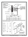
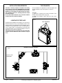
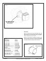
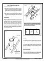
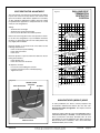
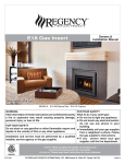
Fig # 1
FIREPLACE DIMENSIONS
TOP
STANDOFFS
CENTER OF FLUE OUTLET
47 5/16
43 1/2
14 1/4
12 5/8
11 11/16
49 3/4
29 7/16
53 7/8
42 3/16
38 1/8
26 7/8
43 1/2
26 7/8
47 5/16
050207-40
TC42.CE
page 3
Important Note for the Commonwealth of Massachusetts:
From Massachusetts Rules and Regulations 248 CMR 5.08:
(a)
For all side wall horizontally vented gas fuelled equipment installed in every dwelling, building or structure used in whole or in
part for residential purposes, including those owned or operated by the Commonwealth and where the side wall exhaust vent termination
is less than seven (7) feet above finished grade in the area of the venting, including but not limited to decks and porches, the following
requirements shall be satisfied.
1.
INSTALLATION OF CARBON MONOXIDE DETECTORS. At the time of installation of the side wall horizontal vented gas
fuelled equipment, the installing plumber or gasfitter shall observe that a hard wired carbon monoxide detector with an alarm and battery
back-up is installed on the floor level where the gas equipment is to be installed, in addition, the installing plumber or gasfitter shall observe
that a battery operated or hard-wired carbon monoxide detector with an alarm is installed on each additional level of the dwelling, building
or structure served by the side wall horizontal vented gas fuelled equipment. It shall be the responsibility of the property owner to secure
the services of qualified licensed professionals for the installation of hard-wired carbon monoxide detectors.
a.
In the event that the side wall horizontally vented gas fuelled equipment is installed in a crawl space or an attic, the hard-wired
carbon monoxide detector with alarm and battery back-up may be installed on the next adjacent floor level.
b.
In the event that the requirements of this subdivision cannot be met at the time of completion of installation, the owner shall have
a period of thirty (30) days to comply with the above requirements; provided, however, that during said thirty (30) day period, a battery
operated carbon monoxide detector with an alarm shall be installed.
2.
APPROVED CARBON MONOXIDE DETECTORS. Each carbon monoxide detector as required in accordance with the above
provisions shall comply with NFPA 720 and be ANSI/UL 2034 listed as IAS certified.
3.
SIGNAGE. A metal or plastic identification plate shall be permanently mounted to the exterior of the building at a minimum
height of eight (8) feet above grade directly in line with the exhaust vent terminal for the horizontally vented gas fuelled heating appliance or equipment. The sign shall read, in print size no less than one-half (1/2) inch in size, “GAS VENT DIRECTLY BELOW. KEEP
CLEAR OF ALL OBSTRUCTIONS”.
4.
INSPECTION. The state or local gas inspector of the side wall horizontally vented gas fuelled equipment shall not approve the
installation unless, upon inspection, the inspector observes carbon monoxide detectors and signage installed in accordance with the provisions of 248 CMR 5.089(2)(a) 1 through 4.
(b)
EXEMPTIONS. The following equipment is exempt from 248 CMR 5.089(2)(a) 1 through 4.
1.
The equipment listed in Chapter 10 entitled “Equipment Not Required To Be Vented” in the most current edition of NFPA 54 as
adopted by the Board; and
2.
Product Approved side wall horizontal vented gas fuelled equipment installed in a room or structure separate from the dwelling,
building or structure used in whole or in part for residential purposes.
(c)
MANUFACTURER REQUIREMENTS – GAS EQUIPMENT VENTING SYSTEM PROVIDED. When the manufacturer of
Product Approved side wall horizontally vented gas equipment provides a venting system design or venting system components with the
equipment, the instructions provided by the manufacturer for installation of the equipment and the venting system shall include:
1.
Detailed instructions for the installation of the venting system design or the venting system components; and
2.
A complete parts list for the venting system design or venting system.
(d)
MANUFACTURER REQUIREMENTS – GAS EQUIPMENT VENTING SYSTEM NOT PROVIDED. When the manufacturer
of a Product Approved side wall horizontally vented gas fuelled equipment does not provide the parts for venting the fuel gases, but identifies “special venting systems”, the following requirements shall be satisfied by the manufacturer.
1.
The referenced “special venting system” instructions shall be included with the appliance or equipment installation instructions;
and
2.
The “special venting systems” shall be Product Approved by the Board, and the instructions for that system shall include a parts
list and detailed installation instructions.
(e)
A copy of all installation instructions for all Product Approved side wall horizontally vented gas fuelled equipment, all venting
instructions, all parts lists for venting instructions, and/or all venting design instructions shall remain with the appliance or equipment at the
completion of the installation.
page 4
TC42.CE
050207-40
Fig. # 2
COMBUSTIBLE FRAMING
AND FINISHWALL ABOVE
STANDOFFS
STEEL FRAMING
STANDOFFS
MAY USE COMBUSTIBLE
FACING MATERIAL IN
THIS AREA
NON-COMBUSTIBLE
ZONE. DO NOT INSTALL
A N Y C O M B U ST I B L E
MATERIAL, ELECTRICAL
WIRING OR GAS
PLUMBING IN THIS
AREA.
NONCOMBUSTIBLE
FINISH MATERIAL
D
E
F
A
B
C
TOP OF SHEET METAL
FIREPLACE FRONT
MANTEL CLEARANCE CHART
REF.
MANTEL
CLEARANCE
A
9"
D
12"
B
6"
E
6 3/4"
C
3"
F
1 1/2"
(0 mm)
Top standoffs ........................0 in.
(0 mm)
Bottom of appliance ..............0 in.
(0 mm)
Adjacent sidewall ..................4 in.
(102 mm)
Ceiling to appliance ............24 in.
(610 mm)
L
Back standoffs ......................0 in.
ING
IL
CE
TE
(0 mm)
N
Side standoffs .......................0 in.
Fig. # 3
M
A
Minimum Clearances to Combustibles:
"
24
Mantel to appliance ..........See Fig. #2
*
Maximum
mantel extension ..........See Fig. #2
Mantel support......................4 in.
(102 mm)
Vertical vent pipe ............1-3/4 in.
(45 mm)
Horizontal vent pipe
Top .............................1-3/4 in.
Sides .........................1-3/4 in.
Bottom .......................1-3/4 in.
(45 mm)
(45 mm)
(45 mm)
050207-40
MANTEL
DEPTH
REF.
**
AD
J
WA ACE
L N
MA L OR T
N
SU TEL
PP
OR
T
4"
"
38
1/8
UNIT MAY BE RECESSED UP TO
6" WITH NON-COMBUSTIBLE
MASONRY TYPE MATERIAL
TC42.CE
page 5
INSTALLATION REQUIREMENTS
The Town & Country Fireplace installation and venting
must conform to the current CAN/CGA-B149 installation
code (in Canada) or the current National Fuel Gas Code,
ANSI Z223.1 (in the USA), and approved per local codes.
Only qualified (licensed or trained) personnel should
install this product.
In the state of Massachusetts, only a licensed Plumber
and Gas Fitter may install this product.
LOCATING THE FIREPLACE
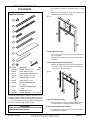
TOP STANDOFFS
The top standoffs are shipped loose inside the fireplace and
must be installed on top of the fireplace as shown in
Fig. #4.
Assembly:
1) Remove the standoffs from inside the fireplace. (See
window frame removal section on pg. 28)
2) Position the standoffs in place and secure with screws
provided.
Fig. # 4
In planning the installation for the fireplace, it is necessary to
determine where the unit is to be installed, location of vent
system and where gas supply piping may be plumbed. Various
installations are possible, such as, into an existing wall, a
corner, a built-in wall or a wall projection (see Fig. #5). Due
to high temperatures, do not locate this fireplace in areas of
high traffic or near furniture or draperies.
The minimum clearances from the fireplace to combustible
surfaces must be adhered to and are shown on Fig. #2
and 3.
Fig. # 5
TOP STANDOFFS
Examples of Common Locations
SEE FIG #9 FOR
DIMENSIONS
page 6
TC42.CE
050207-40
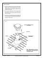
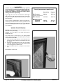
FRAMING AND FINISHING
Note: The fireplace must be in place and venting installed
before framing in or building an enclosure around the
unit.
The Town & Country Fireplace must be framed in as described
below or totally enclosed with non-combustible material, such
as facing brick.
Determine the total thickness of facing material to be used.
A thickness of 3/4" will allow the finishing surface to be flush
with the front of the unit. If preferred, additional masonry type
non-combustible material can be installed above and to the
sides up to 6 inches proud of the appliance. The finishing
material must not interfere with glass frame access.
A Steel Stud Framing Kit is supplied with the fireplace and
must be used unless the fireplace is totally enclosed with
non-combustible material. Assemble the framing kit as per
its instructions. Attach the steel frame to the fireplace once
the fireplace is in its final position. Secure the steel frame to
Fig. # 6
NON-COMBUSTIBLE
ZONE. DO NOT INSTALL
ANY COMBUSTIBLE
MATERIAL, ELECTRICAL
WIRING, INSULATION,
PLASTIC VAPOUR
BARRIER OR GAS
PLUMBING WITHIN THE
STEEL STUD FRAMING
the framing brackets on each side of the unit. Ensure that
the studs are set back far enough to allow for thickness of
finishing surface.
The sides, back and top of the fireplace can be framed in
up to the steel studs and the fireplace standoffs using conventional lumber. Consult local building codes for specific
requirements.
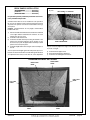
Due to high temperatures, concrete board is supplied with
the fireplace and must be used to sheet in the front of the
fireplace, extending 12" above and 5" to the side of the framing edge bars. See Fig. #7. Standard sheetrock (drywall) may
be used beyond this.
Chase Insulation: When installing this fireplace against a
non-insulated exterior wall or chase, it is recommended that the
outer walls be insulated to same degree as other exterior walls.
Do not place fireplace directly against the insulation. Cover the
insulation and plastic vapour barrier with a solid surface, such
as drywall (sheetrock). Consult local codes. Do not insulate
or use plastic vapour barrier within the framing kit.
STEEL STUD FRAMING KIT
DIMENSIONS
(TC42.FRKITB)
ALL OTHER FRAMING CAN BE
DONE WITH CONVENTIONAL
LUMBER
050207-40
TC42.CE
page 7
Fig. # 7
CONCRETE BOARD
DETAIL
CONCRETE
BOARD
Fig. # 8
NON-COMBUSTIBLE RECESSED
INSTALLATION DETAIL
NON-COMBUSTIBLE
M AS O N RY T Y P E
MATERIAL
CONCRETE
BOARD
STEEL
STUDS
6"
Concrete board (or other non-combustible
material) must extend 12" above and 5" to the
sides of the framing edges.
MINIMUM COMBUSTIBLES FRAMING DIMENSIONS
Fig. # 9
54"
Including Sheetrock
12 5/8"
26 1/8"
54"
54"
3/4"
61 3/4"
21 5/16"
54"
3/4"
61 3/4"
30 1/8"
54"
87 5/16"
WARNING: Fireplace should be in its final location before framing.
page 8
TC42.CE
050207-40
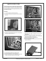
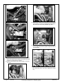
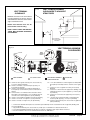
MAESTRO CONTROL SYSTEM
Fig. # 12
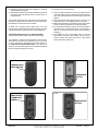
The gas control system is located on the right hand side of
the firebox behind an access panel and the decorative brick
panel. The fireplace is operated via a wall switch that can be
located up to 25 ft away from the fireplace and also by a hand
held remote control unit.
Installation
1) Locate the fireplace in the desired location.
2) Remove access panel from right hand side of the firebox
(Fig. #10)
Fig. # 10
ACCESS PANEL
Fig. # 13
AC ADAPTER
3) Connect a 110v AC electrical supply to the outlet installed
inside the control box (Fig. #11)
Fig. # 11
OUTLET
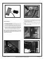
7) Route the control cable as required to the wall control
electrical box.
8) Attach the control cable to the wall control. (Fig. #14)
9) Insert the 4 supplied “AA” batteries into the battery pack
and connect to wall control. (Fig. #15)
10) Fasten the wall switch to the electrical box.
11) Fasten the faceplate to switch
12) Turn on the gas supply and check that all connections are
tight and leak free.
Fig. # 14
4) Connect the gas supply to the valve (Fig. #12)
5) Plug the A/C adaptor into the outlet (Fig. #13)
6) Attach the electrical box for the supplied wall control to the
framing in the desired location (up to 25ft away).
050207-40
TC42.CE
page 9
Fig. # 17
Fig. # 15
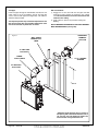
Burner installation
1) Remove the burner from the packaging and install as per
its installation instructions.
2) Connect the flex hoses from the pilot and the main burner
supply to the bulkhead fittings on the firebox. (Fig. #16)
3) Connect the electrical connections from the pilot assembly to the connections in the firebox side. Ensure that the
orange wire from the spark electrode is connected to the
rear of the two connectors in the bulkhead. (Fig. #17)
4) Remove the pressure test point pipe plug from the manifold
test port. The plug is located between the right side lintel
and firebox side. (Fig. #18)
5) Thread the extension piece into the open test port. (Fig.
#19)
6) Attach a pressure gauge onto the hose barb on the now
installed extension piece.
Fig. # 18
Note: If you need to test the supply pressure, turn off the
gas supply before removing the blanking plug from the
supply pressure test port.
Fig. # 16
page 10
Fig. # 19
TC42.CE
050207-40
If this fireplace is to be used on natural gas go
to step 17.
CONVERSION LP
COUNTRY HOME BURNER
Fig. # 20
If the unit is to be used on propane convert as
follows using the components supplied with
this fireplace:
Warning:
This conversion kit shall be
installed by a qualified service
agency in accordance with the
manufacturer's instructions and all
applicable codes and requirements
of the authority having jurisdiction.
If the information in these
instructions is not followed exactly,
a fire, explosion or production of
carbon monoxide may result
causing property damage, personal
injury or loss of life. The qualified
service agency is responsible for
the proper installation of this kit.
The installation is not proper and
complete until the operation of the
converted appliance is checked
COUNTRY HOME & CHALET BURNER
Fig. # 21
Caution: The gas supply and
electrical power shall be shut off
before proceeding with the
conversion.
BLACK DIAMOND BURNER
Fig. # 22
7) On the country home burner remove the two screws securing the air deflector to the grate. (Fig. #20)
8) Remove the manifold assembly from the burner, country
home and chalet burners. (Fig. #21)
The burner tube will have to be removed to expose the
orifice on the black diamond burner. (Fig. #22)
9) With a ½” wrench remove the natural gas orifice (#25) and
replace with propane orifice (#3/32")
10) With a 7/16” wrench loosen the pilot head on the pilot
assembly (Fig. #23)
050207-40
TC42.CE
page 11
Fig. # 23
Fig. # 27
Minimum
rate screw
13) Replace the minimum rate screw with the one provided
in the propane conversion kit supplied with this fireplace.
Ensure that the screw is fully installed. (Fig. #28)
Fig. # 24
Fig. # 28
Fig. # 25
14) Pull off the rubber cap from the top of the pressure regulator. (Fig. #29) The pressure regulator adjustment tube is
now accessible.
Fig. # 29
NG
LP
11) Slide the pilot adjustment band over and ensure that the
hole in the orifice band is showing. (Fig. #25 shows NG
position, Fig. #26 shows LP position)
12) Remove the minimum rate screw located in the valve.
(Fig. #27)
Fig. # 26
Minimum
rate screw
page 12
TC42.CE
15) Press down on the center tube and rotate 90°. The center
tube should stay down. (Fig. #30). Replace the rubber
cap.
050207-40
Fig.# 30
21) Press the center button of the wall control. The fireplace
will shut off.
22) Install the remaining screws in the access panel and
tighten.
23) Remove the pressure gauge and the extension piece and
thread the pressure test pipe plug into the pressure test
port. Thread sealant is required on the threads.
24) Turn the fireplace on and verify that the connections are
tight.
25) Continue installation of the burner as per the burner kit
instructions.
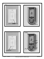
Standing Pilot Function
(only for use where permitted)
16) Sign and date the conversion label supplied and stick it
to valve body.
17) Loosely attach the access panel to the side of the firebox with a few screws. (Fig. #31)
Fig. # 31
The control system on this fireplace is shipped as a non-standing pilot fireplace. If required the system can be converted to
a standing pilot by depressing a recessed button located on
the lower right hand side of the wall control. (Fig. #33) This
should be depressed with a paperclip, pencil or other thin
object. Once activated the pilot will run continuously. Please
check with your local inspector to ensure that this is permitted in your area.
Control System – Remote Control Initial Setup
This fireplace is supplied with a wall control and hand held
remote control. Please note only genuine Town & Country
Fireplace wall controls and hand held remote controls
can be used on this fireplace.
18) Turn on gas and electrical supplies.
19) Press the center button on the wall control (Fig. #32). The
igniter will start to spark. After a short delay the pilot will
light, followed by the main burner.
1) Initial set up of the hand held remote is required. A “learn”
button is located on the lower left hand side of the wall
switch. This should be depressed with a paperclip, pencil
or other thin object. (Fig. #34)
2) Once this has been pressed, press the center button on
the hand held remote. (Fig. #35) The fireplace will then
turn on.
3) Turn off the fireplace by pressing the center button again.
The handset is now synchronized with the fireplace.
Fig. # 32
20) Press the up button on the wall control and hold it for 5
seconds or until a clicking sound is heard from the gas
control. Release the button, check manifold pressure and
ensure that it’s correct. (Fig. #33)
050207-40
TC42.CE
page 13
Fig. # 33
Fig. # 35
STANDING PILOT
BUTTON
Fig. # 34
ON/OFF BUTTON
Fig. # 36
FLASHES
DAY
HOUR:
MIN
HOLD
A1
HOLD
A2
LEARN BUTTON
page 14
TC42.CE
050207-40
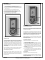
Initial Settings
(time and temperature)
Fig. # 38
1) Press and hold the A1 and A2 buttons at the same time
until the temperature symbol flashes. (Fig. #36)
2) Use the up and down arrows to set preferred temperature
units. (°F or °C)
3) Press OK and the “hour” value will start to flash.
4) Use the up and down arrows to set the “hour” value.
5) Press OK and the “minute” value will flash.
6) Use the up and down arrows to set the “minute” value.
7) Press OK and the “day” value will flash.
8) Use the up and down arrows to set the “day” value.
Fig. # 37
FLAME
UP
ON/
OFF
FLAME
DOWN
Manual Mode
(on remote and wall control)
HOLD
HOLD
9) Press ok to end the initial set up.
Childproof Lock
An additional feature of this remote control is the childproof
lock. To activate this system press and hold the timer and
thermostat buttons for approx. 5 seconds until the “lock”
symbol appears on the remote display. (Fig. #37) The remote
control hand set buttons are now locked and the lock symbol
will reappear every time a button is pressed on the remote
control until the timer and thermostat buttons are pressed
and held again.
Note: The fireplace can still be operated normally using the
wall control even with the remote control buttons locked.
Control System - Operation
Each Town and Country Maestro Control system comes
equipped with a manual mode on the wall control and hand
held remote, and three programmable modes accessible with
the hand remote.
050207-40
Basic operation of the fireplace can be performed with the
wall control or remote hand set. (ON/OFF, as well as flame
modulation UP/ DOWN).
The center button on the remote control can be used to turn
the fireplace ON and OFF. With the fireplace off, press the
center button to turn it on. (The “MAN” and flame icons will be
displayed on the screen) A second push will turn it off. (The
“MAN” and flame icons will disappear from the screen)
When the fireplace is on, the up and down buttons located
above and below the center button are used to modulate the
flame height. (Fig. #38)
Countdown Timer Mode
(Operates the fireplace for a preset length of time)
1) Press the timer button and the time will flash on the lower
center of the display. (Fig. #39)
2) When display is flashing, use the up and down arrows to set
the length of time you would like the fireplace to run. (The
range is 10 minutes minimum to 180 minutes maximum).
(Fig. #41)
3) Press the OK button and the timer is set and the control
is in countdown timer mode.
4) To exit the timer mode press the Program, Manual or
Thermostat buttons. Please note that the first press of the
Manual button will turn the fireplace off.
Program Mode
(to preset up to two on and off periods per day)
The program mode has two settings for weekdays and two for
weekends. The hand held remote comes with the following
pre programmed settings:
TC42.CE
page 15
Weekday Program
(Monday through Friday)
Fig. # 39
Program one (P1) turns ON at 7:00am and turns OFF at
8:00am
Program two (P2) turns ON at 5:00pm and turns OFF at
7:00pm
Weekend Program
(Saturday and Sunday)
TIMER
Program one (P1) turns ON at 9:00am and turns OFF at
10:00am
Program two (P2) turns ON at 6:00pm and turns OFF at
9:00pm
Activate the programs by pressing the program button on the
lower left hand side of the remote hand set. (Fig. #41)
To customize these setting:
1) Hold the program button down until the display flashes.
(P1, weekday ON time - [Fig. #42])
2) Use the up and down buttons to change the time to the
desired ON time.
3) By pressing the OK button, the P1 weekday OFF time will
flash.
4) Use the up and down buttons to set the desired OFF
time.
5) Press the OK button and the P2 weekday ON time will
flash.
Fig. # 40
Fig. # 42
TIMER RUN
DURATION
Fig. # 41
PROGRAM
page 16
TC42.CE
050207-40
6) Repeat the process to set the P2 weekday, P1 weekend
and P2 weekend programs.
7) When the P2 OFF time is set and the OK button is pressed
the display will stop flashing and the remote will be in
program mode.
The program settings are now stored in the remote handset
and will not change unless the above process is repeated or
the batteries are removed from the handset.
To switch out of program mode, simply press one of the
manual, timer or thermostat mode buttons. Please note that
if the manual button is pressed it will turn the fireplace off.
Thermostatic Mode (Only for use where permitted)
(Operates the fireplace within a set temperature range)
The fireplace is shipped with thermostatic mode function
deactivated. If this function is permitted for use in your area
it can be activated by depressing the recessed button on
the underside of the hand held remote. (Fig. #43) Once
activated, the thermostat symbol (Fig. #44) will be displayed
when the thermostat button is pressed
Fig. # 43
To activate a set point temperature:
1) Press the thermostat button on the lower right hand side
of the hand held remote to activate the thermostat mode.
(Fig. #45) The temperature and thermostat symbols will
appear.
2) Press and hold the thermostat button for 5 seconds. The
temperature icon on the display will flash. (Fig. #46)
3) While the temperature icon is flashing use the up and down
arrows to set the temperature to the desired setting.
4) Once the desired setting is reached, press the OK button.
If the OK button is not pressed the icon will continue to
flash for 5 seconds and then set itself to the temperature
displayed.
5) The fireplace is now in thermostatic mode. To exit the
thermostatic mode press the program, manual or timer
buttons. Please note that the first press of the manual
button will turn the fireplace off.
Fig. # 45
THERMOSTATIC
MODE BUTTON
THERMOSTAT
BUTTON
Fig. # 44
DEACTIVATED
THERMOSTAT
SYMBOL
050207-40
Fig. # 46
TEMPERATURE
SETTING
TC42.CE
page 17
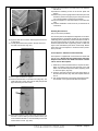
VENTING
WALL TERMINATION VENTING
Before installing venting for this unit, the installer should read
these instructions to insure that the proper vent configuration
has been selected.
Use only Town and Country Termination kits #:
TCVT.WTA - Wall Termination Kit
TCVT.RTA - Roof Termination Kit
Exterior wall opening:
Determine the exact position of the fireplace so that the vent
pipe is centred (if possible) between two building framing
members. Consult your local building codes prior to proceeding. The vent kit will accommodate up to a maximum wall
thickness of 12 inches.
Vent system components approved for use with the Town and
Country Fireplace are shown in Fig. #49.
1) Having determined the position of the fireplace, cut and
frame a 14-1/2 inches opening centred at a minimum
height of 74-1/4 inches above the floor. The opening may
be round or square. Height of the opening will vary with
each installation. As the horizontal vent run increases, so
does the minimum vertical rise (see Fig. #52).
Various combinations of vertical and horizontal runs may
be used. Refer to Fig. #52 and 53 for details. For optimum
performance and flame appearance, keep the vent length
to a minimum and limit the number of elbows. Connections
between each vent system component must be tightly joined,
secured with sheet metal screws and sealed. A horizontal run
of vent should have a 1/4" rise for every 1 ft. of run towards
the termination.
CAUTION: UNDER NO CONDITION SHOULD COMBUSTIBLE MATERIAL BE CLOSER THAN 1 3/4 INCHES FROM
THE SIDES AND BOTTOM AND 1 3/4 INCHES FROM
THE TOP OF A HORIZONTAL SECTIONS OF THE VENT
PIPE AND 1 3/4 INCHES FROM A VERTICAL SECTION
OF PIPE.
IMPORTANT: When locating the opening, it should be
noted that vent terminal clearances must be maintained.
See "Vent Terminal Clearances" section for proper
clearances.
A minimum 2 foot length of pipe is required for any wall termination. With this minimal vertical rise in combination with a
90° elbow, a maximum horizontal run of 18 inches is permitted
(see Fig. #52 and 53). For longer horizontal runs greater than
18 inches, increase vertical rise appropriately. The rise and
run must be constrained to the boundaries of the chart shown
in fig. #52. The horizontal run of vent should have a 1/4" rise
for every 1 ft. of run towards the termination.
Fig. # 47
WINDOW
FRAME
HEARTH EXTENSION
While a hearth extension is not required
for this fireplace, one is recommended for
aesthetic reasons. The hearth extension
should be noncombustible and must not
be any more than 1" above the bottom of
the fireplace. If thicker, fireplace must be
raised up accordingly.
Caution: Hearth extensions thicker than
1" will interfere with the window frame.
1"
MAX
1/4"
HEARTH
EXTENSION
page 18
TC42.CE
WINDOW
TRACK
SUBFLOOR
050207-40
Fig. # 48
WALL THIMBLE AND VENT
MUST NOT PROTRUDE
BEYOND SIDING
Wall thimble:
Where a vent pipe passes through a combustible wall, a wall
thimble/shield must be used to retain insulation and maintain
proper clearances. The wall thimble may be cut to length for
various wall thicknesses up to 12" thick.
Fig. # 49
Vent System
Components
Town &
Country
12" Pipe Length ........................... TCVT.811X12
18" Pipe Length ........................... TCVT.811X18
24" Pipe Length ........................... TCVT.811X24
48" Pipe Length ........................... TCVT.811X48
12" Adjustable Pipe Extension ..... TCVT.811X12ADJ
45° Elbow .................................... TCVT.811XLB45
90° Elbow .................................... TCVT.811XLB90
Wall/Offset Support ..................... TCVT.811XOS
Measure the wall thickness including the siding. Trim the
shield to match the wall thickness. Position the wall thimble
from inside through the 14-1/2" opening. Properly trimmed,
the thimble should be flush with the outer wall surface.
Fig. # 50
TRIM TO LENGTH
Wall Termination Kit ..................... TCVT.WTA
Roof Termination Kit .................... TCVT.RTA
Wall Shield/Ceiling Firestop ......... TCVT.THIMA
Roof Flashing, Adjustable ............ TCVT.811FLADJ
Roof Flashing, Flat ...................... TCVT.811FLFLT
Roof Flashing, Steep ................... TCVT.811FLSTP
or any that fits 11" pipe
050207-40
TC42.CE
page 19
Vent pipe:
Install vent pipe through the wall thimble and attach to flue
outlet collar on top of the fireplace. Secure all joints with
screws and seal with approved "High Temp." self-adhesive
aluminum tape provided.
The fireplace position may need to be adjusted to ensure
that the vent pipe does not protrudes beyond the outer
wall or be recessed any more than 12 inches.
Fig. # 51
Wall vent terminal:
1) Engage the 8" vent collar with the vent pipe and slide
terminal into place. Attach the terminal to the outside
wall. The vent terminal must not be recessed into the
exterior wall or siding.
2) Caulk in place to prevent any moisture entering the
building.
NOTE: MINIMUM CLEARANCES TO THE VENT TERMINAL
MUST BE MAINTAINED (see Fig. #52).
HORIZONTAL
TERMINAL
TCVT.9360
WALL SHIELD
THIMBLE TCVT.
THIMA
12" VENT PIPE
TCVT.811X12
ELBOW
TCVT.811XLB90
14 1/2" FRAMED
OPENING
24" VENT PIPE
TCVT.811X24
* 74 1/4"
* Minimum height from the floor to center of
the opening with a maximum horizontal run of
18" using TC vent. The height will need to be
increased with a longer horizontal run.
page 20
TC42.CE
050207-40
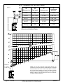
WALL TERMINATION VENTING CHART
Fig. # 52
**
D
A
B
C
Minimum rise
Pipe length
Maximum run
Pipe length
Maximum
74 1/4”
1-24”
18"
1-12"
78 1/2”
1-12" 1-18"
75 3/4"
1-48" 1-12"
84 1/2”
1-24" 1-12"
11' 2"
2-48" 1-24"
90 1/2”
1-24" 1-18"
15' 10 1/2"
3-48" 1-24"
1-12"
98 1/4”
1-48”
20’ 10 1/2”
5-48"
For other rise/run combinations see chart below
** All dimensions are approximate. Both rise and run may vary with
different combinations of pipe.
Minimum
2' Length
of Pipe
NOTE: The vent must not exceed a total length of 68 feet. Any
combination of rise and run may be used but must be constrained
to the boundaries of this chart. A total of 3 90° elbows or combination of other elbows equalling 90° can be used without reducing
horizontal run. For each additional 90° elbow, or an equal combination of elbows, reduce horizontal vent run by 2 feet. Ensure
vent pipe is properly supported.
*
050207-40
Minimum Vent Pipe Centerline Height
TC42.CE
page 21
ROOF TERMINATION VENTING CHART
Fig. # 53
**
D
A
B
C
Minimum rise
Pipe length
Maximum run
Pipe length
Maximum
74 1/4”
1-24”
29"
1-12"
78 1/2”
1-12" 1-18"
77 1/4"
1-48" 1-12"
84 1/2”
1-24" 1-12"
11' 1 1/2"
2-48" 1-24"
90 1/2”
1-24" 1-18"
15' 10"
3-48" 1-24"
1-12"
98 1/4”
1-48”
20' 10”
5-48"
For other rise/run combinations see chart below
** All dimensions are approximate. Both rise and run may vary with
different combinations of pipe.
Minimum
2' Length
of Pipe
page 22
NOTE: The vent must not exceed a total length of 68 feet. Any
combination of rise and run may be used but must be constrained
to the boundaries of this chart. A total of 4 90° elbows or combination of other elbows equalling 90° can be used without reducing
horizontal run. For each additional 90° elbow, or an equal combination of elbows, reduce horizontal vent run by 2 feet. Ensure
vent pipe is properly supported.
TC42.CE
050207-40
ROOF TERMINATION VENTING
Fig. # 56
Ceiling and Roof opening:
A
14 1/2"
1) Determine the exact position of the fireplace so that the
vent pipe is centered (if possible) between two building
framing members. Lay out the vent system path, minimizing the number of elbows and length of vent. Consult your
local building codes prior to proceeding.
2) Cut and frame a 14-1/2" opening in the floor, ceiling and
roof where the vent system will pass. Size of the opening
through the roof may need to be increased as the pitch of
the roof increases. Avoid cutting rafters.
B
Ceiling firestop:
Where a vent pipe passes through a floor or ceiling, a ceiling
firestop must be used to retain insulation and maintain proper
clearances.
From below, push the ceiling firestop through the opening
and secure in place. If the firestop is used to penetrate a
floor, the outer shield may be trimmed in length. If the firestop
penetrates into an attic, leave the shield full length to keep
insulation away from the vent pipe. Additionally, after the vent
pipe is in place, install a storm collar on top of the shield. This
will prevent loose insulation from falling into the area between
the vent pipe and the shield.
Size of the opening will have to increase with the pitch
of the roof to ensure a 1 3/4 inch air space clearance
between support sleeve and combustibles. Additional
space may need to be provided if the side air intake
box is attached prior to installation.
Roof Pitch
0/12
4/12
6/12
8/12
12/12
Fig. # 54
A
14 1/2"
16 1/2"
18"
19 3/4"
24"
B
7 1/4"
8 3/4"
10"
11"
13 3/4"
VENT PIPE
Vent pipe:
1) Install the first section of vent pipe onto the collar on top
of the fireplace. Secure in place with screws and seal with
approved "High Temp." self-adhesive aluminum tape provided.
2) Continue adding vent pipe lengths up and through the
firestop(s) and through the roof. The vent pipe must extend
at least 24" above the roof.
Seal the vent pipe as per "Vent Pipe Sealant" section.
Roof support bracket:
ROOF SUPPORT
BRACKET
(TCVT.93915)
050207-40
Slip the roof support bracket down over the vent pipe. Rotate
the 90° brackets to accommodate roof pitch.Attach the brackets
to the roof joists with nails or building screws. Tighten the band
around the vent pipe and secure in place with screws.
TC42.CE
page 23
Roof vent terminal:
1) Place the roof flashing over top of the vent pipe and nail
securely to the roof using roofing nails, top and sides
UNDER shingles, lower end OVER shingles to provide
a watershed. Make weather tight by sealing with roofing
compound (see Fig. #57).
2) Place the storm collar down over the vent pipe until it
is level. Tighten storm collar for a snug fit. Apply a thick
horizontal ring of mastic around the pipe at top of storm
collar (see Fig. #57).
3) Lower the roof vent terminal cap over the vent pipe and
secure in place with screws provided (see Fig. #56). Seal
screw heads and joint with caulking to prevent any moisture
entering the venting system.
Fig. # 56
VERTICAL TERMINATION CAP
(TCVT.9365)
VENT PIPE
MASTIC
STORM COLLAR
(TC42.90665)
FLASHING
Note: Adjustable for various
roof pitches, from flat roof to
12/12 pitch roof.
page 24
TC42.CE
050207-40
VENT TERMINAL MINIMUM
CLEARANCES TO ADJACENT
STRUCTURES
Fig. # 57
VENT TERMINAL
CLEARANCE
Minimum clearances to the vent terminal
must be maintained as shown in Fig. #57
and 58. Measure clearances to the nearest
edge of termination hood.
36"
(91.5 cm)
24"
(61 cm)
NOTE: Vent terminal must not be
recessed into a wall or siding.
24"
(61 cm)
NOTE: LOCAL CODES OR REGULATIONS MAY REQUIRE DIFFERENT
CLEARANCES.
48"
(122 cm)
ADJACENT
STRUCTURES
OR FENCE
VENT TERMINAL MINIMUM
CLEARANCES
Fig. # 58
INSIDE
CORNER
DETAIL
G
V
A
H
D
E
C
V
L
V
B
F
FIXED
CLOSED
B
V
OPENABLE
V
OPENABLE
V
FIXED
CLOSED
I
G
V
B
J
A
A
V VENT TERMINAL
A
AIR SUPPLY INLET
A= clearances above grade, veranda, porch, deck, or balcony
[* 12 inches (30 cm) minimum]
B= clearance to window or door that may be opened [* 12
inches (30 cm) minimum]
C= clearance to permanently closed window [minimum 12
inches (30 cm) recommended to prevent condensation on
window]
D= vertical clearance to ventilated soffit located above the terminal within a horizontal distance of 2 feet (60 cm) from the
center-line of the terminal [30 inches (76 cm) minimum]
E= clearance to unventilated soffit [30 inches (76 cm) minimum]
F= clearance to outside corner [6 inches (15 cm) minimum]
G= clearance to inside corner [6 inches (15 cm) minimum]
AREA WHERE TERMINAL
IS NOT PERMITTED
M
V
K
A
G GAS METER
H= * not to be installed above a meter/regulator assembly within
3 feet (90 cm) horizontally from the center-line of the regulator
I= clearance to service regulator vent outlet [* 6 feet (1.8 m)
minimum]
J= clearance to nonmechanical air supply inlet to building or the
combustion air inlet to any other appliance [* 12 inches (30
cm) minimum]
K= clearance to a mechanical air supply inlet [* 6 feet (1.8 m)
minimum]
L= ^ clearance above paved side-walk or a paved driveway
located on public property [* 7 feet (2.1 m) minimum]
M= clearance under veranda, porch, deck, or balcony [30 inches
(76 cm) minimum**]
^ a vent shall not terminate directly above a side-walk or paved driveway which is located between two single family dwellings and
serves both dwellings*
** only permitted if veranda, porch, deck, or balcony is fully open on a minimum of 2 sides beneath the floor*
* as specified in CGA B149 Installation Codes, Note: local Codes or Regulation may require different clearances
* for U.S.A. Installations follow the current National Fuel Gas Code, ANSI Z223.1
050207-40
TC42.CE
page 25
VENT PIPE SEALANT
(supplied with the appliance)
All outer joints of the vent pipe must be sealed with the approved "High Temp." self-adhesive aluminum tape provided.
Wrap the tape completely around the joint and press firmly
in place.
Fig. #59
VENT PIPE
SEALANT
APPROVED
"HIGH TEMP"
SELF-ADHESIVE
ALUMINUM
TAPE
VENT PIPE
page 26
TC42.CE
050207-40
VENT RESTRICTOR ADJUSTMENT
The vent restrictor is located on the underside of the firebox
top. The unit leaves the factory with the vent restrictor wide
open. The restrictor is built into the appliance for secondary
air flow adjustment. Adjustment enables tuning the airflow
for optimum flame appearance and performance for a wide
variety of vent configurations.
Setting:
- determine the vent height
- determine the vent horizontal length
- from the chart determine the restrictor position
WALL AND ROOF
TERMINATION
RESTRICTOR
POSITION
Fig. # 61
48'
40'
1" OPEN NG
3/4" OPEN LP
Refer to the chart in Fig. #61 for the correct position of restrictor for the vent configuration of your installation. Restrictor
positions are based upon lab tests. The ideal position may
vary slightly with installation.
Restrictor position is closed too much if the flame has the
following characteristics:
- Flame is excessively tall and lifting.
- Flame lacks movement.
- Flame soots.
Restrictor position is open too much if the flame has the following characteristics:
- Flame height is low.
- Flame has excessive movement.
To adjust the restrictor:
- Loosen the screw holding the restrictor.
- Push the restrictor back to its intended opening.
- Tighten the screw
30'
30'
2" OPEN
22'
20'
20'
18'
3" OPEN
12'
10'
10'
FULLY OPEN
8'
6'
Fig. # 60
4'
LOOSEN SCREW
TO ADJUST
VENT RESTRICTOR
2'
18"
OPENING
4'
6'
8'
10'
12'
14'
16'
18'
20'
0'
0'
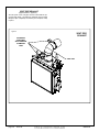
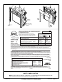
MANUFACTURED (MOBILE) HOME
In some jurisdictions, the Town & Country Fireplace may
be installed in Manufactured Homes after the "first sale".
Consult local codes for approval. The fireplace must be
fastened in place.
SHOWN WITH REAR BRICK
PANEL IN PLACE
050207-40
Install in accordance with the current standard Mobile Homes,
CAN/CSA Z240 MH (in CANADA), and the Manufacturer's
Home Construction and Safety Standard, Title 24 CFR,
Part 3280 or the current Standard for Fire Safety Criteria for
Manufactured Home Installations, Sites and Communities
ANSI/NFPA 501A (in the U.S.A.).
TC42.CE
page 27
GAS SUPPLY
Caution: The gas line should be installed by a qualified
service person in accordance with all building codes.This
section is intended as a guide for qualified technicians
installing this appliance. Consult local and/or national
building codes before proceeding.
A gas supply line access hole is located at the bottom right
side of the Control Box. Gas valve inlet accepts a 3/8" N.P.T.
fitting. Correct gas line diameter must be used to assure
proper operation.
The gas control is equipped with a capture screw type pressure test port, therefore it is not necessary to provide an 1/8
inch N.P.T. plugged tapping pressure port for checking gas
pressure immediately upstream of the gas supply connection
to the appliance.
Correct gas pressure requirement:
Natural Gas
Propane
5.0" wc
12.5" wc
Max. Pressure
13.9" wc
13.9" wc
Manifold Pressure
Maximum
Minimum
3.8" wc
1.75" wc
11.0" wc
5.5" wc
Min. Pressure
(For purpose of input adjustment)
WINDOW FRAME REMOVAL
Warning: Turn off the fireplace, and allow ample time for the
unit to cool before proceeding.
Caution: The ceramic glass is very fragile, and should be
handled with care.
Fig # 63
The window frame is held in place by two spring-loaded
latches and are operated by a removable handle. The handle
is located in the Control Box.
1) Insert the latch handle onto the catch located 6” down
from the top corners. Rotate up to disengage each of the
two catches.
2) Tilt the top of the window frame out to clear the top edge
of the unit. Grasp the sides of the frame and lift up and
out to disengage from its bottom track.
3) Place the window frame in a safe place to avoid damage.
Reassemble in reverse order.
Fig # 62
page 28
TC42.CE
050207-40
BRICK PANELS INSTALLATION
(HERRINGBONE ................. TCPN.547)
(TUSCAN ............................. TCPN.548)
(HERITAGE RED .................. TCPN.552)
Fig. # 65
ADJUSTABLE "V" BRACKET
For porcelain panel kit (TCPN.549) installation see instructions provided with panel kit.
A Firebox Panel Set has to be installed for safe operation.
Do not use the fireplace without panels Unpack and inspect
all panels. The panels need to be installed before the logs
are in place.
Caution: The Brick Panels are very fragile, and should be
handled with care.
1) Remove the Side Panel Retainers located on the underside
of the upper firebox heatshield. The retainers are each
held in place by one screw.
2) Install the Lower Rear Panel.
3) Install the Left Side Panel by inserting the bottom of the
panel in first and then angling it up into position. It may
be necessary to push the upper firebox shield up to allow
panel to move freely into place.
4) Install the Right Side Panel using the same technique as
the left.
may be necessary. Adjust the angle of the bracket by hand
to ensure a snug fit.
The rear panel is held tight against the side panels by two "V"
brackets located on the firebox rear wall. Although the brackets
are adjusted at the factory for the best fit, some adjustment
5) Install the Rear Upper Panel.
6) Re-install the Side Panel Retainers.
7) Install the Left and Right Front Panels.
Fig. # 64
REAR LOWER PANEL
HERRINGBONE PANEL SET SHOWN
REAR UPPER
PANEL
REAR LOWER
PANEL
RIGHT SIDE
PANEL
LEFT SIDE
PANEL
LEFT FRONT
PANEL
050207-40
RIGHT FRONT
PANEL
TC42.CE
page 29
LIGHTING INSTRUCTIONS
FOR YOUR SAFETY READ BEFORE LIGHTING
WARNING: If you do not follow these instructions
exactly, a fire or explosion may result causing
property damage, personal injury or loss of life.
A. This appliance is equipped with an ignition device which automatically lights the pilot. Do not try to light the pilot by hand.
B. BEFORE LIGHTING smell all around the appliance area for gas.
Be sure to smell next to the floor because some gas is heavier
than air and will settle on the floor.
WHAT TO DO IF YOU SMELL GAS:
- Do not try to light any appliance.
- Do not touch any electric switch; do not use any phone in your
building.
- Immediately call your gas supplier from a neighbour's phone.
Follow the gas supplier's instructions.
- If you cannot reach your gas supplier, call the fire department.
C. Use only your hand to push in or turn the gas control knob. Never
use tools. If the knob will not push in or turn by hand, don't try
to repair it, call a qualified service technician. Force or attempted repair may result in a fire or explosion.
D. Do not use this appliance if any part has been under water.
Immediately call a qualified service technician to inspect the
appliance & to replace any part of the control system & any gas
control which has been under water.
LIGHTING INSTRUCTIONS
1. STOP! Read the safety information above on this label.
2. Set wall switch/ hand held remote to lowest setting.
3. This appliance is equipped with an ignition device which
automatically lights the pilot. Do not try to light the pilot by
hand.
4. Push the "On/ Off" switch to the fireplace Off.
5. Allow sufficient length of time (minimum 5 minutes) for any
gas in the combustion chamber to escape. If you still smell
gas, STOP! Follow "B" in the safety information above on
this label. If you don't smell gas, go to the next step.
6. Push the "On/ Off" switch to turn the fireplace on.
- If the burner does not light, repeat steps 4 through 6.
- If the burner will not light or stay lit after several
tries,push the "On/ Off" switch to the fireplace off and
call your service technician or gas supplier.
Note: Sufficient time must be allowed for air to escape
from lines if the unit is being lit for the first time.
7. Set fireplace to desired setting by using either the wall
switch or hand held remote.
TO TURN OFF GAS TO APPLIANCE
1. Set wall switch / hand held remote to lowest setting.
2. Push the "on/ off" switch to the "Off" position.
3. Turn off all electric power to the appliance and remove
backup batteries if service is to be performed or for extended
shutdown.
Due to high surface temperatures, keep children, clothing and furniture away. Keep burner and control compartment
clean. See installation and operating instructions accompanying the appliance.
A cause de la temperature elevee des parios, tenir eloignes les enfants, les vetements et les meubles. Maintenir propres le
bruleur et le compartiment de commande. Voir les instructions relatives a l'installation et au fonctionnement qui accompagnent
l'appareil.
CAUTION:
Hot while in operation. Do not touch. Severe burns may result. Keep children, clothing,
furniture, gasoline and other liquids having flammable vapours away. Keep burner and control compartment
clean. See installation and operating instructions accompanying the appliance.
ATTENTION:
L'appareil est chaud lorsqu'il fonctionne. Ne pas toucher l'appareil. Risque de
brûlures graves. Serveiller les enfants. Garder les vêtements, le meubles, l'essence ou autres liquides
produisant des vapeurs inflammables loin de l'appareil. S'assurer que le brûleur et le compartiment des
commandes sont propres. Voir les instructions d'installation et d'utilisation qui accompagnent l'appareil.
310106
5051.173
5-TC30
FIRST FIRE
When lit for the first time, the fireplace will emit a slight odour for a couple of hours. This is due to the curing
of paints, sealants and lubricants used in the manufacturing process. This condition is temporary. Open
doors and windows to ventilate area. Smoke and fumes caused by the curing process may cause discomfort
to some individuals.
It is normal for fireplaces fabricated of steel to give off some expansion and/or contraction noises during
the start up or cool down cycle. Similar noises are found with your furnace heat exchanger or cook stove
oven.
page 30
TC42.CE
050207-40
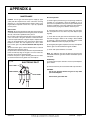
APPENDIX A
MAINTENANCE
Annual Inspection:
Caution: Turn off gas and electrical power supply (if applicable) and allow ample time for unit to cool before servicing
appliance. It is recommended that the fireplace and its venting should be inspected at least once a year by a qualified
service person.
a) Remove glass panel and log set. Inspect logs and burner
assembly for soot buildup. If excessive buildup of soot is
present, have a qualified service person inspect and adjust unit
for proper combustion. Clean logs and burner with a brush or
vacuum cleaner, paying close attention to burner ports.
Glass Panel:
Warning: Do not operate fireplace with glass panel removed,
cracked or broken. Replacement of the glass panel should be
done by a licensed or qualified service person.
Do not strike or otherwise impact the glass in anyway that may
cause it to break. If the glass becomes cracked or broken,
it must be replaced before using the fireplace. Replacement
glass can be obtained from your nearest Town and Country
FireplacesTM dealer. The size required is 42" x 36" x 5mm.
Use ceramic glass only. Do not substitute with any other
type.
To remove broken glass, remove window frame as noted in
"Window Frame Removal" section.
Unclip the Glass Retainer Clip located at the top of the Window
Frame. Pull the top edge of the glass out of the frame first,
then lift it up and out of the bottom edge.
Install the new piece of glass with the gasket into the frame
so that the thicker bead of gasket faces the fireplace.
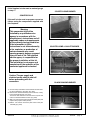
b) Check the pilot system for proper flame size and operation. Clean pilot free of soot, dust or any other deposits. (See
Fig. #66)
Fig. # 66
ELECTRONIC PILOT
PILOT FLAME
c) Check that the vent pipe and vent terminal are open and
free from blockage or debris. If the venting is disassembled
for cleaning, it must be properly assembled and re-sealed.
Refer to VENTING section for proper procedure.
d) Check glass panel gasket, replace if necessary. It is important
that the glass seal be maintained in good condition.
e) Check and replace batteries as needed.
Note: The appliance area must be kept clear and free from
combustible materials, gasoline and other flammable vapours
and liquids.
Periodically:
a) Viewing glass may be cleaned as necessary with fireplace
glass cleaner.
b) Exterior finish may be cleaned with mild soap and water.
CAUTION:
Do not use abrasive cleaners on glass or any other
part of the fireplace.
FLAME SENSOR
ELECTRODE
Do not clean glass when hot.
050207-40
TC42.CE
page 31
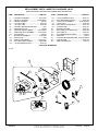
REPLACEMENT PARTS
(WHEN ORDERING, INCLUDE PART NUMBER WITH DESCRIPTION)
ITEM
DESCRIPTION
PART NO.
ITEM
DESCRIPTION
PART NO.
12 .......... PANEL, RIGHT SIDE, HRGBONE ..... 5098.5464.B
.............. PANEL, RIGHT SIDE, TUSCAN ..........5098.5474.B
.............. PANEL, RT SIDE, HERITAGE RED .. 5098.552.3.B
13 .......... PANEL, UP. BACK, HERRINGBONE ...5098.54625
.............. PANEL, UPPER BACK, TUSCAN ..........5098.5471
.............. PANEL, UP BACK, HERITAGE RED .....5098.552.1
14 .......... PANEL, LEFT SIDE, HRGBONE ....... 5098.5463.B
.............. PANEL, LEFT SIDE, TUSCAN ........... 5098.5473.B
.............. PANEL, LT SIDE, HERITAGE RED ... 5098.552.2.B
1............ GLASS FRAME..................................... TC42.9020
2............ REPLACEMENT GLASS (c/w gasket) . GLAS.2086
.............. GLASS RETAINER, TOP (c/w gasket) ..... 9050.001
.............. GLASS GASKET KIT ...................................2086.1
.............. FRAME & GLASS ASSEM. ..........TC42.9020ASSY
3............ CONTROL ASSEMBLY ........................ TCCV.9270
4............ SPRING LATCH ASSEMBLY ................ TC42.9024
.............. REMOVABLE LATCH HANDLE ......... 5000.9028.A
5............ BRICK PANEL RETAINER ....................... 1908.603
6............ FIREBOX SHIELD (c/w insulation) ... TC42.900401
7............ FLUE DAMPER ............................................9004.5
8............ FIREBOX REAR SHIELD..............................9001.5
9............ PANEL, RIGHT BASE, BRICK .................5098.546
.............. PANEL, RIGHT BASE, TUSCAN............ 5098.5401
.............. PANEL, RT BASE, HERITAGE RED .....5098.552.6
10 .......... PANEL, LEFT BASE, BRICK ...................5098.545
.............. PANEL, LEFT BASE, TUSCAN ............ 5098.54015
.............. PANEL, LT BASE, HERITAGE RED ......5098.552.5
11 .......... PANEL, LWR BACK, HERRINGBONE...5098.5462
.............. PANEL, LOWER BACK, TUSCAN ..........5098.5472
.............. PANEL, LW BACK, HERITAGE RED.....5098.552.4
.............. PANEL SET, HERRINGBONE ............... TCPN.547
.............. PANEL SET, TUSCAN ............................ TCPN.548
.............. PANEL SET, HERITAGE RED ................ TCPN.552
All parts may be ordered from your nearest Town and Country
FireplacesTM dealer. Contact Town and Country FireplacesTM
for the location of the dealer nearest you.
Fig. # 67
14
13
12
11
10
9
8
7
4
5
6
3
1
2
page 32
TC42.CE
050207-40
REPLACEMENT PARTS - MAESTRO CONCEALED VALVE
(WHEN ORDERING, INCLUDE PART NUMBER WITH DESCRIPTION)
ITEM ..... DESCRIPTION...................................... PART NO.
ITEM ...... DESCRIPTION.................................... PART NO.
1 ........... CONTROL ASSEMBLY ........................TCCV.9270
|2......... VALVE c/w FITTINGS ......................TCCV.500501
|3......... WIRING HARNESS .................................. 5005.21
|4......... 1/4" FLEX TUBE ..................................... 5019.225
|5......... 1/2" FLEX TUBE ..................................... 5019.223
|6......... CONTROL MOUNTING BRACKET ............... 9271
|7......... IGNITION MODULE .................................... 5005.2
|8......... IGNITION/ SENSOR WIRES .............TCCV.50625
|9......... PRESSURE TEST ASSEMBLY ......... TC30.92145
|10....... AC ADAPTOR ........................................... 5005.03
11 .......... BULKHEAD ASSEMBLY ...................... TC30.9284
|12....... INLET PLATE ................................................. 9284
|13....... INLET PLATE GASKET ...................... 5068.93147
|14....... ELEC BULKHEAD GASKET ................. 5068.9285
|15....... 1/2" BULKHEAD FITTING ...................... 5019.102
|16....... 1/4" BULKHEAD FITTING ...................... 5019,101
|17....... ELEC BULKHEAD FITTING ................... 5005.026
18 ......... UTILITY BOX ASSEMBLY .............TCCV.5024405
|19....... UTILITY BOX .......................................... 5024.405
|20....... ELECTRICAL RECEPTACLE ................. 5024.406
|21....... COVER PLATE ....................................... 5024.407
22 ......... BATTERY HOLDER ................................ 5005.043
23 ......... WALL SWITCH COVER PLATE ............. 5005.042
24 ......... WALL SWITCH ....................................... 5005.041
25 ......... 25' COMMUNICATION CABLE ................. 5005.06
26 ......... WING NUT .................................................. 5049.3
27 ......... CONTROL BOX WELDED ASM. .TCCV.9270WLD
28 ......... TEST FITTING ........................................ 5019.104
29 ......... REMOTE HAND SET................................ 5005.05
| NOT SOLD SEPARATELY
Fig. # 68
27
1
26
4
5
3
2
6
11
25
12
10
7
16
24
17
9
13
8
22
14
15
28
18
23
29
21
20
050207-40
19
TC42.CE
page 33
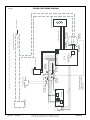
page 34
Power Vent Fan
TC42.CE
Red
AF-4000
1/4” Male
Connector
Black
Orange
White
Pull connectors apart
to connect to optional
power vent
Black
Green
1/4” Female
Connector
Pressure Switch
1/4” Female
Connector
(+) (-)
Low volt relay
Inside the module
Module
SWI
120 Volt Power
1/4” Male
Connector
AC Adaptor
1/4” Female
Connector
1/4” Male
Connector
1/4” Male
Connector
1/4” Female
Connector
Communication Wires
120 Volt Hot wire (Black)
120 Volt Common wire (White)
Optional Power Vent Kit provided by Town & Country
Wall Switch Receiver
120 Volt Power
Fig. # 69
POWER VENT WIRING DIAGRAM
050207-40
WALL TERMINATION KIT
WALL SHIELD/CEILING FIRESTOP THIMBLE
TCVT.WTA
TCVT.THIMA
Fig. # 71
Fig. # 70
WALL
TERMINAL
TCVT.9360
16 1/2"
16 1/2"
WALLSHIELD/CEILING
FIRESTOP THIMBLE
TCVT.THIMA
9 5/8"
ROOF TERMINATION KIT
TCVT.RTA
Fig. # 72
16 1/2"
VERTICAL
TERMINATION CAP
TCVT.9365
9"
STORM COLLAR
TC42.90665
CEILING FIRESTOP
TCVT.THIMA
ROOF SUPPORT
BRACKET
TCVT.93915
050207-40
TC42.CE
page 35
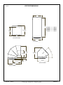
Fig. # 73
VENT PIPE DIMENSIONS
11"
*
10 15/16"
9 1/2"
12" Pipe ............. 10 1/4"
18" Pipe ............. 16 1/4"
24" Pipe ............. 22 1/4"
48" Pipe ............. 46 1/4"
TCVT.811X12ADJ
11 1/8"
TCVT.811X _ _
45°
13 13/16"
12 9/16"
8 5/16"
10 5/16"
15 7/8"
7/16"
1 5/16"
13 1/8"
TCVT.811XLB45
TCVT.811XLB90
page 36
TC42.C
120506-40
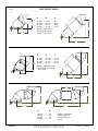
Fig. # 74
VENT OFFSET CHART
A
10 7/8"
1 1/4”
11 3/8"
B
C
A
12" Pipe ....... 18 5/8" ..........18"
18" Pipe ....... 22 7/8" ..........22 3/8"
24" Pipe ....... 27 1/8" ..........26 1/2"
48" Pipe ....... 44 1/16" ........43 1/2"
C
Adding an adjustable section to pipe will increase
offset by 2 1/8" to 6 3/4"
1 1/4”
B
A
B
C
A
12" Pipe ....... 13 7/16" ........23 1/4"
18" Pipe ....... 17 9/16" ........27 5/8"
24" Pipe ....... 21 7/8" ..........31 3/4"
48" Pipe ....... 38 3/4" ..........48 7/8"
C
Adding an adjustable section
to pipe will increase offset by
2 1/8" to 6 3/4"
1 1/4”
B
A
20”
20"
1 1/4”
1 1/4“
B
18 3/4"
A
B
12" Pipe .............. 29"
18" Pipe ............. 35"
24" Pipe ............. 41"
48" Pipe ............. 65"
120506-40
Adding an adjustable
section to pipe will
increase offset by 3"
to 9 1/2"
TC42.C
page 37
STEEL STUD FRAMING KIT
1. Top Frame Assembly
•Lay out studs (2) and (4) on a large flat surface, see Fig.
TC42.FRKITB
#1.
•Using the screws provided (1), attach the header (5) and
Each Kit Contains:
the stud plate (6) to the top studs (4).
Fig. # 75
1
5
2
4
3
2
6
4
5
2
6
2. Attach Side Studs (Legs)
7
•
Attach the side studs (3) to the top of the header studs
(5), see Fig. #76.
•
Fasten the side studs (3) at the bottom using the base
plates (9).
8
10
3. Attach the Assembled Frame to the Unit
9
•
Item Part #
1
2
3
4
5
6
7
5049.9912
9093.03
9093.1
9093.22
9094
9094.21
9098.01
8
9098.51
9 9194.5
10 5049.993
Description
Qty.
SCREW, TEKS #8 x 1/2”
Pkg. 40
STUD, SIDES, 53 3/4”L
2
STUD, OUTER SIDES, 53 3/4”L
2
STUD, CENTER, 15 7/16”L
2
STUD, HEADER, 53 3/4”L
1
STUD, PLATE, 47 1/4”L
1
CONCRETE BOARD, TOP
1
12” x 53 3/4”
CONCRETE BOARD, SIDE
2
5” x 38”
BASE PLATE 4 3/4”L
2
SCREW, DRYWALL, 1 1/4” Pkg. 30
The Steel Stud Framing Kit is wider than required in the installation manual. An additional stud was added to each side
for stability making the side concrete board 5” wide instead
of 1 1/2” as specified. Once fully assembled, the framing kit
fits into a 54” wide x 54” high framed opening.
Align the assembled frame to the unit framing brackets,
see Fig. #77. Attach at the fastening points through the
access holes in the side studs (3).
Fig. # 76
5
3
3
9
4. Secure to Existing Framing
9
•Secure the frame assembly to existing framing through
the stud top plate (5) and the stud base plates (9).
WARNING!
EDGES ARE SHARP, ALWAYS WEAR GLOVES WHEN
WORKING WITH SHEET METAL.
6. Install Concrete Board Top and Sides
•Use drywall screws (10) to install the concrete board top
(7) and sides (8), Fig. #78.
page 38
TC42.CE
050207-40
Stud Upper
Plate
Fig. # 77
Fig. #78
7
8
Framing
Brackets
Access holes
to mounting
screws
Stud Base
Plate
8
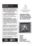
9(17('*$6),5(3/$&(127)2586(:,7+62/,')8(/
)2<(5$8*$=¬e9$&8$7,211(3$687,/,6(5$9(&
'8&20%867,%/(62/,'(
$16,=E&6$E9HQWHG*DV)LUHSODFHV
&$1&*$0*DV)LUHG$SSOLDQFH)RU8VH$W+LJK$OWLWXGHV
&HUWL¿HGIRU&HUWL¿pSRXU&DQDGDDQG86$
02'(/
02'(/(
7&
6(5,(6
6(5,(
0$'(,1&$1$'$
)$%5,48($8&$1$'$
&
:+
7KLV$SSOLDQFHLV(TXLSSHG)RU8VH:LWK
&HW$SSDUHLOHVWeTXLSp3RXU8WLOLVH$YHF
1$785$/*$6
*$=1$785(/
/3*$6
/3*$=
)2586(:,7+
(1&$6('¶(03/2,$9(&
1$785$/*$6
/3*$6
'8*$=1$785(/ '8*$=/3
0LQLPXPVXSSO\SUHVVXUH3UHVVLRQPLQLPXPG¶DOLPHQWDWLRQ
)RUWKHSXUSRVHRILQSXWDGMXVWPHQWGDQVOHEXWGHUpJOHUO¶DOLPHQDWLRQ
0D[LPXPVXSSO\SUHVVXUH3UHVVLRQPD[LPXPG¶DOLPHQWDWLRQ
0DQLIROGSUHVVXUH3UHVVLRQGHODWX\DXWHULH0D[LPXP
LQZFSRFH
N3D
LQZFSRFH
N3D
LQZFSRFH
N3D
LQZFSRFH
N3D
LQZFSRFH
N3D
LQZFSRFH
N3D
2UL¿FH6L]H'LDPHWUHGHO¶LQMHFWXHU
PP
´
,QSXW%78KUN:(QWUHH%78KN:
0D[
0LQ
0D[
0LQ
PP
2SWLRQDOFRPSRQHQWV5HPRWH+HDW.LW7&5+.$eOpPHQWVIDFXOWDWLIV.LWj'LVWDQFHGHOD&KDOHXU7&5+.$
%ORZHUHOHFWULFDOUDWLQJYK]$1RUPHVHOHFWULTXHVGXYHQWLODWHXUYK]$
7KLVDSSOLDQFHHTXLSSHGIRUDOWLWXGHVIWP&HWXQLWpHVWFRQoXSRXUGHVDOWLWXGHVYDULDQWHQWUHSLHGVP,Q&DQDGDDOVR
FHUWL¿HGIRULQVWDOODWLRQLQDEHGURRPRUDEHGVLWWLQJURRP$XVVLFHUWL¿pSRXULQVWDOODWLRQGDQVXQHFKDPEUHjFRXFKHURXXQHVDOOHGHVpMRXU7KLVDSSOLDQFH
PXVWEHLQVWDOOHGLQDFFRUGDQFHZLWKORFDOFRGHVLIDQ\LIQRQHIROORZWKHFXUUHQW&$1&*$%&DQDGDRU$16,=86$,QVWDOODWLRQ&RGHV
,QVWDOOHUO¶DSSDUHLOVHORQOHVFRGHVRXUqJOHPHQWVORFDX[RXHQO¶DEVHQFHGHWHOVUqJOHPHQWVVHORQOHVFRGHVG¶LQVWDOODWLRQ&$1&*$%&DQDGDRU$16,
=86$HQYLJHXU
0$18)$&785('02%,/(+20(7KLVDSSOLDQFHLVRQO\IRUXVHZLWKWKHW\SHRIJDVLQGLFDWHGRQWKHUDWLQJSODWHDQGPD\EHLQVWDOOHGLQDQDIWHUPDUNHW
SHUPDQHQWO\ORFDWHGPDQXIDFWXUHGPRELOHKRPHZKHUHQRWSURKLELWHGE\ORFDOFRGHV6HHRZQHUVPDQXDOIRUGHWDLOV
)$%5,48(=02%,/(0$,621&HWDSSDUHLOGRLWrWUHXWLOLVpXQLTXHPHQWDYHFOHW\SHGHJD]LQGLTXpVXUODSODTXHVLJQDOpWLTXHHWSHXWrWUHLQVWDOOpGDQVXQH
PDLVRQSUpIDEULTXpHPRELOHLQVWDOOpHjGHPHXUHVLOHVUqJOHPHQWVORFDX[OHSHUPHWWHQW9RLUODQRWLFHGXSURSULpWDLUHSRXUSOXVGHGpWDLOV&HWDSSDUHLOQH
SHXWrWUHFRQYHUWLjG¶DXWUHVJD]VDXIVLXQHWURXVVHGHFRQYHUVLRQFHUWL¿pHHVWXWLOLVpH
,QVWDOOLQDFFRUGDQFHZLWKWKHFXUUHQWVWDQGDUG0RELOH+RPHV&$1&6$=0+LQ&$1$'$DQGWKH0DQXIDFWXUHU¶V+RPH&RQVWUXFWLRQDQG6DIHW\
6WDQGDUG7LWOH&)53DUWRUWKHFXUUHQW6WDQGDUGIRU)LUH6DIHW\&ULWHULDIRU0DQXIDFWXUHG+RPH,QVWDOODWLRQV6LWHVDQG&RPPXQLWLHV$16,1)3$
$LQWKH86$&HWDSSDUHLOGLRWrWUHLQVWDOOpFRQIRUPHPpQWDX[H[LJHQFHVGHODQRUPH&$1&6$=0+HQYLJXHXUGHO¶$&125,QVWDOODWLRQVGHJD]
GDQVOHV&RQVWUXFWLRQV0RELOHV
)2586(:,7+*/$66'2256&(57,),(':,7+7+($33/,$1&(21/<328587,/,6$7,2181,48(0(17$9(&/(63257(6,19(55(&(57,),e(6
$9(&/¶$33$5(,/
0,1,080&/($5$1&(672&20%867,%/(6&/$,5$1&(60,1,0$/(6$9(&/(6&20%867,%/(
/HIWDQG5LJKWVLGHDUHGHWHUPLQHGZKHQIDFLQJWKHIURQWRIWKHDSSOLDQFH/HVF{WpVGURLWHWJDXFKHVHGpWHUPLQHQW
HQVHPHWWDQWGHYDQWO¶DSSDUHLOHWHQOXLIDLVDQWIDFH
7RS%DFNDQG6LGH6WDQGRIIV6RPPHW$UULqUHHW&{Wp%XWpH
6LGHZDOOWR$SSOLDQFH'XPXUODWpUDODO¶DSSDUHLO
&HLOLQJWR$SSOLDQFH3ODIRQGDO¶DSSDUHLO
0DQWHOWR$SSOLDQFH'XPDQWHDXDO¶DSSDUHLO
0D[LPXP0DQWHO([WHQVLRQ$OORQJHPHQWPD[LPXPGXPDQWHDX
6HH,QVWDOODWLRQ0DQXDOIRUPRUHGHWDLO9R\H]GHV'LUHFWLYH
GHO¶,QVWDOODWLRQSRXUSOXVGpWDX[
0DQWHO6XSSRUWV6XSSRUWVGXPDQWHDX
9HQW3LSH'pFKDUJH]OH7X\DX
LQSR
LQSR
LQSR
LQSR
LQSR
PP
PP
PP
PP
PP
3DFL¿F(QHUJ\
)LUHSODFH3URGXFWV/WG
'XQFDQ%ULWLVK&ROXPELD
&DQDGD
LQSR
PP
LQSR
PP
:$51,1*,PSURSHULQVWDOODWLRQDGMXVWPHQWDOWHUDWLRQVHUYLFHRUPDLQWHQDQFHFDQFDXVHLQMXU\RUSURSHUW\GDPDJH5HIHUWRWKHRZQHU¶VLQIRUPDWLRQ
PDQXDOSURYLGHGZLWKWKLVDSSOLDQFH)RUDVVLVWDQFHRUDGGLWLRQDOLQIRUPDWLRQFRQVXOWDTXDOL¿HGLQVWDOOHUVHUYLFHDJHQF\RUWKHJDVVXSSOLHU
$9(57,66(0(178QHLQVWDOODWLRQXQUpJODJHXQHPRGL¿FDWLRQXQHUpSDUDWLRQRXXQHQWUHWLHQPDOHIIHFWXpSHXWFDXVHUGHVGRPPDJHVPDWpULHOVRXGHV
EOHVVXUHV9RLUODQRWLFHGHO¶XWLOLVDWHXUTXLDFFRPSJQHO¶DSSDUHLO3RXUGHO¶DLGHRXGHVUHQVHLJQHPHQWVVXSSOpPHQWDLUHVFRQVXOWH]XQLQVWDOODWHXUXQWHFK
QLFLHQDJUppRXOHIRXUQLVVHXUGHJD]
&
7&&
SAFETY LABEL LOCATION
NOTE: The Safety Label is located on a plate found in a slot between the left hand side lintel and the left
hand side window frame. This plate is attached to the lintel with a cable.
050207-40
TC42.CE
page 39
Phone: 1-877-715-2664
Web site: www.townandcountryfireplaces.net
2975 Allenby Rd., Duncan, B.C. V9L 4T8
Printed in Canada