1
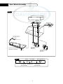
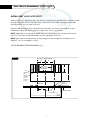
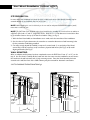
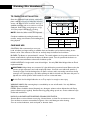
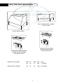
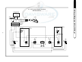
Dynamic Cooking Systems, Inc.
THE PROFESSIONAL VENT HOODS
Use and Installation Guide
Models:
DCS-VH-48HS
DCS-VH-48S
DCS-VH12-36HS
DCS-VH12-36S
DCS-VH-36HS
DCS-VH-36S
DCS-VH-30HS
DCS-VH-30S
A Message To Our Customers
Thank you for selecting this DCS Professional Vent Hood. Because of its unique features, we have developed this
Use and Installation Guide. It contains valuable information on how to properly operate and maintain your new
Vent Hood for years of safe and enjoyable cooking.
To help serve you better, please fill out and return the Ownership Registration Card and keep this guide handy,
as it will help answer questions that may arise as you use your New Vent Hood.
For your convenience, product questions can be answered by a DCS Customer Service
Representative by phone: 1-888-281-5698, or Fax: 714-372-7003,
or by mail:
DCS
Attention Customer Service,
5800 Skylab Road, Huntington Beach, CA 92647
WARNING
To reduce the risk of electrical shock or injury to persons all Vent Hoods must be installed with ventilators that
have been approved for use with the hood. See Table A of this instruction manual for a listing of approved
ventilators.
PRECAUTION
Do Not store or use gasoline or any other flammable vapors and liquids in the vicinity of this or any other
appliance.
PLEASE RETAIN THIS MANUAL
FOR FUTURE REFERENCE.
1
Table Of Contents
INTRODUCTION:
The DCS Vent Hood Models have been designed with the ultimate in household convenience in mind.
Features include High Capacity,Variable Speed Blower, Commercial Style dishwasher-safe filters, Easyto-Clean inside liner, and Illuminating Halogen Lighting, all packaged in a stylish, welded-seam exterior.
Before proceeding with installation, please read this installation guide and observe all safety precautions
and warnings.
NOTE: Installation of this DCS Vent Hood must comply with all local codes.
IMPORTANT- Save these instructions for the Local Electrical Inspector’s use.
INSTALLER- Leave these instructions with the unit for the owner.
SAFETY PRACTICES & PRECAUTIONS...............................................................................3
PLANNING THE INSTALLATION ..............................................................................................4
INNER LINER REMOVAL ..................................................................................................................4
VENT HOOD ASSEMBLY .................................................................................................................5
VENT HOOD INSTALLATION (WITH SOFFIT) .........................................................6-7
VENT HOOD INSTALLATION (WITHOUT SOFFIT) .................................................8
FINISHING THE INSTALLATION ...............................................................................................9
DUCT INFORMATION ....................................................................................................................10
DCS VH SERIES SPECIFICATIONS .........................................................................................11
HOW TO OBTAIN SERVICE ........................................................................................................12
WARRANTY ............................................................................................................................................13
WIRING DIAGRAM ......................................................................................................................14-15
2
Safety Practices & Precautions
WARNING: To reduce the risk of a range top grease fire:
A) Never leave surface units unattended at high settings. Boilovers cause smoking and greasy
spillovers that may ignite. Heat oil slowly on low or medium settings.
B) Always turn hood “ON” when cooking at high heat or when cooking flaming foods.
C) Clean ventilating fans frequently. Grease should not be allowed to accumulate on fan or filter.
D) Use proper pan size. Always use cookware appropriate for the size of the surface element.
Make-Up air may be necessary to prevent air flowing down chimney, unsealed door, window, or fireplace
opening.
WARNING: To reduce the risk of fire, electrical shock, or injury to persons, observe the following
guidelines.
A) Installation and Electrical Wiring Must Be Performed By Qualified Personnel In Accordance With All
Applicable Codes & Standards, Including Fire-Rated Construction.
B) To Prevent Backdrafting, sufficient air is needed to maintain proper combustion and safe exhausting
of gases through the flue (chimney) of fuel burning equipment. Follow the cooking equipment
manufacturers guideline and safety standards such as those published by the National Fire
Protection Association (NFPA) and the American Society for Heating, Refrigeration and Air
Conditioning Engineers (ASHRAE), and the local code authorities.
C) Use caution when cutting or drilling into walls or ceilings as not to damage electrical wiring and
other hidden utilities.
CAUTION:To Reduce the risk of fire and to properly exhaust air, be sure to duct air to outside. -do not
vent exhaust air into spaces within walls or ceiling, nor into attics, crawl spaces, or garages.
NOTE: unit MUST be vented to the outside of the building.
WARNING:To reduce the risk of electrical shock or injury to persons, all vent hoods must be installed
with ventilators that have been approved for use with the hood.
Ventilator Use:
*All Ventilator Models used
in DCS Professional Vent
Hoods are approved by
Underwriters Laboratory
TABLE A:
Vent Hood Model use with Ventilator Model
DCS-VH-48HS
DCS-IB12 (1200 CFM)
DCS-VH-48S
DCS-IB12 (1200 CFM)
DCS-VH12-36HS DCS-IB12 (1200 CFM)
DCS-VH12-36S DCS-IB12 (1200 CFM)
DCS-VH-36HS
DCS-IB6 (600 CFM)
DCS-VH-36S
DCS-IB6 (600 CFM)
DCS-VH-30HS
DCS-IB6 (600 CFM)
DCS-VH-30S
DCS-IB6 (600 CFM)
3
Planning The Installation
BACKDRAFT DAMPER:
We recommend that a backdraft damper be used in all Vent Hood installations. Cold weather installations necessitate the use of a backdraft damper to minimize the flow of cold air into the room. A nonmetallic thermal break should also be installed to minimize conduction of outside temperatures
through the ductwork. Locate the thermal break as close as possible to where the ducting enters the
heated portion of the house.
PLANNING THE INSTALLATION:
Before beginning installation of the Vent Hood and Ventilator, PLAN OUT the entire installation procedure beforehand, considering the following areas:
1. HOOD SIZE & LOCATION- (The hood should be as wide or wider than the cooking appliance with
the hood being centered on the appliance.Vertically, the bottom of the hood should be between 30”36” above the appliance cooking surface).
2. DUCTING- (ducting transitions, air flows to outside? Use of Backdraft damper? ...etc.)
3. ELECTRICAL REQUIREMENTS- (120 Volts, 60 Hz, 15 AMP Service, Local Codes...etc.)
4. ADEQUATE MOUNTING SURFACES- (location of wall studs, additional support for safe wall
mounting...etc.)
HANDLING NOTE- This Hood has been inspected prior to shipping to be free of defects. Due to the
weight of the Vent Hood and Ventilator and to prevent scratching or denting the unit, we recommend the use of
two installers to move, place, and secure the Vent Hood to avoid personal injury or damage to the Hood.
INNER LINER REMOVAL:
The DCS Professional Vent Hood has been designed into (2) major assemblies to accommodate easy
and safe installation. The following procedure is best done with the Hood on its back on a padded surface. The inside liner assembly can be separated from the outer hood assembly by removing the (12)
inner perimeter screws- (3 each side/front/back). Once these screws have been removed, the liner
assembly can slide down to gain access to the male/female disconnect plug- See Fig.8 on page 5. After
the disconnect plug has been unplugged, the liner assembly can be set aside until the hood has been
installed into the soffit or wall.
MODEL IDENTIFICATION:
DCS-VH-36HS (w/ Heat Lamps)
DCS-VH-36S (standard)
DCS-VH-48HS (w/ Heat Lamps)
DCS-VH-48S (standard)
DCS-VH12-36HS (w/ Heat Lamps)
DCS-VH12-36S (standard)
4
DCS-VH-30HS (w/ Heat Lamps)
DCS-VH-30S (standard)
Vent Hood Assembly
FIG.08
DCS Duct Cover (6" or 12" Height)
Rough-In Kit
junction box
Rough-In Kit
A
B
junction box
Through junction box on
rough-in kit, connect to
house wiring
to blower motor
Hood Inner Liner (Remove)
( 48" Model Liner Shown)
FIG.07
Model DCS-IB12 Blower
DCS VH 48
DCS VH12 36
Model DCS-IB6 Blower
DCS VH 36
DCS VH 30
control panel
Blower
Hood Lights
Hood Light Bulb-2ea.
- +
L. Heat Lamp Blower Speed
(not all models)
5
R. Heat Lamp
(not all models)
Vent Hood Installation (with soffit)
SITE PREPARATION:
This DCS Professional Vent Hood has been designed to accommodate installation into a
1) soffit structure (ceiling mount), or, for sites without a soffit structure.
2) directly into the wall through holes provided in the rear panel of the vent hood (wall mount). When
mounting the hood to a soffit, it is recommended to also utilize the rear panel holes to gain additional stability and minimize any vibration noise. We suggest that the final framing and wall finishing
be done with the vent hood at the site to more accurately locate ductwork and electrical service.
CONSTRUCT SOFFIT FRAMING:
1) For a site with a soffit, use 2” x 4”s to construct the soffit framing as shown below in Fig. 1. Note
that a minimum opening of 10” is needed to accommodate the ductwork. With the centerline of
the installation marked, nail down the 2” x 4”s (wide side down) so that their inner edges are those
specified from the centerline. -see Figs.1 & 3 pg.7
Note: The second (outer) set of 2” x 4”s are not necessary on the 30” Models installation.
2) Make 2 wood shims (2” x 10-1/2” x drywall thickness). Attach them to the framing as shown in
Fig.2. Mount shims flush with inner edges of framing and with front edges 11-1/2” from finished back
wall.
FIG.02
FIG.01
10in"imum
M
"A"
SHIMS
"A"
D WID
T
H
Finished Drywall
"A" = Center line to inner edge
of 2 x 4's. -see fig.4.
6
"
1/2
11-
HOO
Vent Hood Installation (with soffit)
INSTALL VENT HOOD INTO SOFFIT:
At this point in the installation process, the inner liner should be removed from the Hood and set aside
(see-Pgs 5 & 6).With the liner set aside, there is clear access to the Soffit mounting holes and wall
mounting holes in the rear panel of the unit.
Once the soffit framing has been completed, place assembled vent hood (hood, rough-in kit, and
ventilator) into place and secure hood to the soffit frame with 6 wood screws.
NOTE: Additionally, we recommend the installer utilize the holes provided in the rear panel of the hood to
secure the hood to the rear wall and minimize any noise and vibration of the unit.
NOTE: Assure that the mounting screws are long enough to be driven through the wood shims into the
installed 2” x 4”s for total support. -see fig.3
-GO TO FINISHING THE INSTALLATION- Pg. 9
FIG.03
TOP VIEW (48" MODEL SHOWN)
"B"
"B"
Rough-in Kit
(23-1/2 x 10-1/2")
ALL MODELS
12"
2 x 4's
installed per
Fig. 1
25"
3/8" Soffit
mounting
holes in
Vent Hood
(6 total)
2 x 4's in Soffit
Outer 2 x 4's
(48" Models only)
FRONT VIEW
"A"
Rough-in Kit
Soffit Mounting Screws (6)
7
CEILING DRYWALL
Vent Hood Installation (without soffit)
SITE PREPARATION:
In cases where the installation site does not have a soffit structure, the Vent Hood assembly may be
secured directly to the wall from the rear of the unit.
NOTE- When installing the vent hood directly to the rear wall, an adequate structural wall support (studs)
must exist to secure the unit.
NOTE- The DCS Duct Cover should be ordered and installed when installing the vent hood in a site without a
soffit. DCS offers both a 6” and 12” height Duct Covers. Keep the 6 or 12 inch dimension in mind when allowing for clearance between the top of the Vent Hood and the ceiling. (see Fig. 4)
1. With the Vent Hood width, and installation site in mind, mark the centerline of the installation.
2. See the chart in Fig.4 to determine the centerline to centerline dimension of wall mounting holes
for the particular model being installed.
3. Cut away enough drywall (if installed) to expose 2 vertical studs (1 on each side of the Hood
center line) It will be necessary to A) construct a plywood wall insert (See Fig 5) or B) install
aligning wall studs. (See Fig 6).
WALL MOUNTING:
After an adequate wall structure has been completed, secure the DCS Duct Cover (6” or 12”) to the
top of the vent hood. Carefully lift the hood with the duct cover into the installation site and secure
the hood into the wall structure with 6 (six) mounting screws. Once the Hood assembly has been
secured to the wall, the front of the Soffit Chimney may be removed for ductwork connections.
-GO TO FINISHING THE INSTALLATION Pg.9
FIG.05
FIG.06
10"imum
Min
10"imum
Min
HOOD
HOOD
WIDTH
WIDTH
"C"
Additional
Wall Studs
Installed
"C"
Centerline of
installation space.
No additional
wall studs
needed
Plywood Sheet
(wall hole cut out x drywall thickness")
8
Finishing The Installation
TO FINISH THE INSTALLATION:
FIG.04
REAR VIEW of VENT HOOD (48" Model Shown)
Once the ventilation hood has been mounted in
place it will be necessary to install the electrical
service. All electrical work should be done by a
qualified electrician and must conform to all local
standards. Refer to the wiring diagrams on Pgs.
14-15, for proper hook-up and grounding.
CEILING DRYWALL
6" or 12"
Duct Cover
3-1/2"
Hood Centerline
6-1/2"
CL
18"
6-1/2"
NOTE: Black=live,White=neutral, Green=ground
"C"
Complete installation by making ductwork connections, testing unit functions, and installing & finishing drywall.
MODEL
CARE AND USE:
"C"
"A"
(see fig.1)
"B"
"C"
(see fig.3) (see fig.4 above)
All 48" Vent Hoods
9-1/2"
13"
13"
All 36" Vent Hoods
9-1/2"
12.7/16"
9"
All 30" Vent Hoods
9-1/2"
12.7/16"
9"
CONTROLS- We recommend you turn your
hood on before you begin cooking to establish fresh air flow. After you've finished cooking, let the
blower run for a few minutes to clear the air and help keep the kitchen fresh and clean.
BLOWER- The blower is operated with 2 controls. The switch adjacent to the speed control turns the
blower on/off, while the speed control adjusts the blower speed. Turn the speed knob clockwise to
increase and counterclockwise to decrease the blower speed.
HOOD LIGHTING- A single switch controls both lights. Use only 50W Max. Halogen Narrow Flood
replacement bulbs.
CAUTION: Halogen lamps are constructed of a glass bulb with a pressurized internal filament tube that
operates at high temperatures and could unexpectedly shatter. Should the outer bulb break, particles of
extremely hot glass could be discharged into the fixture enclosure and/or surrounding environment, thereby
creating a risk of personal injury or fire.When replacing the bulb, let the bulb cool, and assure that power to
light has been turned off. Never allow hot bulb to come into contact with water.
Do Not Touch the Hood Light Bulbs when in use.They may be hot enough to cause injury.
WARMING LAMPS- Each warming lamp is controlled by its own on/off switch. Use only R40 size,
250W Max. Infrared bulbs.
FILTERS- Filters should be cleaned frequently in a detergent solution and are dishwasher safe. Empty
grease collection tray/s regularly. Remove filter/s by gently pulling up and out. Grease collection tray/s
are beneath each filter/s.
UNPLUG the BLOWER MOTOR BEFORE CLEANING VENTILATOR.
-Remove filters to access blower motor plug. Vacuum blower to clean. Do not immerse in water.
-Do not allow an excessive accumulation of grease. -Use a mild detergent when cleaning.
-Do not use harsh abrasives, steel wool pads, or abrasive cloths.
9
Duct Information
GENERAL:
10"
- When planning the path for ducting to the outside, keep in
mind the following guidelines:
- Minimize use of elbows and transitions in ductwork as to
maximize air flow to outside of building. An efficient airflow
path contributes to the overall efficiency of the Vent Hood.
- DCS recommends the use of smooth wall ducting, not
flexible ductwork.
- Transitions are required from rectangular to round ducting
11"
10-1/2"
18-5/8"
4-5/8"
Vertical Duct Transition
DCS-IB12 BLOWER Requires one of the following 4-1/2” x 18” to 10” round transitions
(purchase separately)
Model 19052-01-Vertical discharge
Model 19052-02-Rear discharge
Model 19052-03-Left discharge
- Duct tape may be used at ducting joints.
DCS-VH-48 / DCS-VH12-36 REQUIREMENTS:
- DCS recommends the use of 10” round ducting which provides 78.6 sq. In. of surface area.
- Alternate duct sizes in rectangular style may be used. If a rectangular duct style is used, the duct
must equal at least 78.6 sq. In. for best results. (Example- 3-1/4” x 24” duct = 78 sq. In.)
- Maintain consistent ducting square area as to avoid reduced air flow. [ie.- With a VH-48 Hood,
connecting a 4”x13” (52 sq. In.) to a 10” round (78.6 sq. In.) is not recommended]
DCS-VH-36/30 REQUIREMENTS:
- DCS recommends the use of 7” round ducting which provides 34.7 sq. In. of surface area.
- Alternate duct sizes in rectangular style may be used. If a rectangular duct style is used, the duct
must equal at least 34.7 sq. In. for best results.
DUCT ACCESSORIES:
- Wall Caps and Roof Caps must have free open area equal to duct size diameter.
- Note that a Sealed Back Draft Damper may reduce air delivery.
10
DCS VH Series Specifications
12"
"
6",12
"
18
Specify 48",36",30"
Spec
ify 48
DCS VH SERIES SOFFIT CHIMNEY
DUCT COVER
25"
",36"
,30"
12"
DCS VH SERIES HOODS
7"
7-1/4"
3"
3/4"
4-1/2"
23-1/2"
3"
10-1/4"
3/4"
23-1/2"
10-1/4"
10-1/4"
10-1/4"
12-1/4"
18-1/4"
10-1/4"
10-1/4"
MODEL DCS IB6 BLOWER
AND ROUGH IN KIT
MODEL DCS IB12 BLOWER
AND ROUGH IN KIT
MODEL DCS IB6 BLOWER
VOLTS HZ
120
60
AMPS
3.3
CFM
600
DUCT
7” ROUND
MODEL DCS IB12 BLOWER
120
5.0
1200
10” ROUND
60
11
Service
HOW TO OBTAIN SERVICE:
Before you call for service:
1) Is the circuit breaker tripped or the fuse blown?
2) Is there a power outage in the area?
For warranty service, contact your local DCS authorized service agency. Provide him with the Model
Number, Serial Number, and date of installation, and a brief description of the problem. If you need
assistance in locating the authorized service agency in your area please contact our DCS Customer
Service Department for an authorized service agent near you, our number is (888) 281-5698.
Your satisfaction is of the utmost importance to us. If a problem cannot be resolved to your
satisfaction, please write or fax us at: 714-372-7003.
Write:
DCS
Attention: Consumer Relations
5800 Skylab Road
Huntington Beach, CA 92647
12
Warranty
LENGTH OF WARRANTY:
One (1) Year Full parts and Labor Covers the entire product
Five (5) Year Limited warranty covering the switches and motor.
DCS WILL PAY FOR
All repair labor and parts found to be defective due to materials or workmanship for one full year
“IN HOME” warranty during the first year of ownership. This does not apply if the unit was
subjected to other than normal household use. Service must be provided by Authorized Factory Agent
during normal working hours. No charges will be made for repair or replacement at the location of
initial installation or factory for parts returned pre-paid, through the dealer and claimed within the
warranty period, and found by DCS to be defective.
Replacement will be F.O.B. DCS, and DCS will not be liable for any transportation costs, labor costs, or
export duties. This warranty shall not apply, nor can we assume responsibility for damage that might
result from failure to follow manufactures instructions or local codes, where the appliance has been
tampered with or altered in anyway or which, in our judgement, has been subjected to misuse,
negligence, or accident. Implied warranty shall not extend beyond the duration of this written
warranty.This warranty is in lieu of all warranties expressed or implied and all other obligations or
liability in connection with the sale of this appliance.
DCS WILL NOT PAY FOR
•
•
•
•
•
•
•
Installation or start-up.
Shipping damage.
Service by an unauthorized agency.
Damage or repairs due to service by an unauthorized agency or the use of unauthorized parts.
Service during other than normal working hours.
Improper installation, such as improper hook-up, etc.
Service visits to teach you how to use the appliance; correct the installation; reset circuit breakers
or replace home fuses.
• Repairs due to other than normal household use.
• Damage caused from accident, abuse, alteration, misuse, incorrect installation or installation not in
accordance with local codes.
• Units installed in non-residential application such as day care centers, bed and breakfast centers,
churches, nursing homes, restaurants, hotels, schools, etc.
This warranty applies to appliances used in residential applications; it does not cover their use in
commercial situations. This warranty is for products purchased and retained in the 50 states of the
U.S.A., the District of Columbia and Canada.This warranty applies even if you should move during the
warranty period. Should the appliance be sold by the original purchaser during the warranty period, the
new owner continues to be protected until the expiration date of the original purchaser’s warranty
period. This warranty gives you specific legal rights.You may also have other rights which vary from
state to state.
13
Wiring Diagram DCS VH 48
48" VENT HOOD WIRING DIAGRAM
1200 CFM MOTOR
JUNCTION BOX
(L1)
BLK
(N)
WHT
WN-3
(GROUND)
GRN
6
8
MOTOR
PLUG
BLOWER
MOTOR
WHT
BLK
5
16
7
1
2
3
4
5
CONNECTORS:
6 FEMALE
1
2
3
4
5
6
9
2
14
MALE
USED ON
HS MODELS
ONLY
3
USED ON
HS MODELS
ONLY
LEFT HEAT
LIGHT
brass
17
RIGHT HEAT
LIGHT
17
brass
zinc
zinc
14
19
19
20
18
19
9
20
LEFT
LIGHT
10
17
1a
1b
12
2
1
LEFT
HEAT LIGHT
SWITCH
10
14
15
2b
1a
1b
15
SPEED
CONTROL
1a
1b
11
FAN
SWITCH
4
19
3
WN-2 WN-1
LIGHT
SWITCH
1a
1b
12
17
13
RIGHT
HEAT LIGHT
SWITCH
RIGHT
LIGHT
11
13
1
(L1)
BLK
36" / 30" VENT HOOD WIRING DIAGRAM
(N)
WHT
600 CFM MOTOR
WN-3
BLOWER
MOTOR
8
(GROUND)
GRN
6
16
WH
BLK
1
2
1
2
3
3
9
19
15
LEFT
LIGHT
12
1
5
4
5
14
6
FEMALE
6
MALE
3
17
zinc
19
11
2
4
USED ON
HS MODELS
ONLY
HEAT
LIGHT
brass
CONNECTORS:
5
7
18
17
18
1a
1b
HEAT LIGHT
SWITCH
11
15
15
1a
2b
SPEED
CONTROL
1b
1a
1b
4
10
FAN
SWITCH
14
3
WN-2 WN-1
LIGHT
SWITCH
9
10
RIGHT
LIGHT
13
12
1
2
Wiring Diagram DCS VH 30/36
JUNCTION BOX