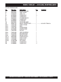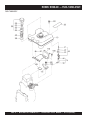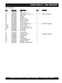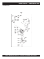
1
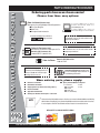
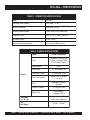
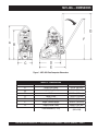
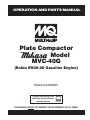
OPERATION AND PARTS MANUAL
Plate Compactor
Model
MVC-40G
(Robin EH09-2D Gasoline Engine)
Revision #4 (06/06/07)
To find the latest revision of this
publication, visit our website at:
www.multiquip.com
THIS MANUAL MUST ACCOMPANY THE EQUIPMENT AT ALL TIMES.
l
PAGE 2 — MVC-40G PLATE COMPACTOR — OPERATION & PARTS MANUAL — REV. #4 (06/06/07)
NOTE PAGE
MVC-40G PLATE COMPACTOR — OPERATION & PARTS MANUAL — REV. #4 (06/06/07) — PAGE 3
TABLE OF CONTENTS
Multiquip MVC-40G
Plate Compactor
ROBIN EH09-2D Engine
(EPA)
Table Of Contents ..................................................... 4
Parts Ordering Procedures ....................................... 5
Specifications ............................................................ 6
Dimensions ............................................................... 7
Safety Message Alert Symbols .............................. 8-9
Rules For Safe Operation.....................................10-11
General Information ................................................ 12
Components (Plate Compactor) ............................. 13
Components (ROBIN EH09-2D Engine) ................. 14
Inspection ........................................................... 15-16
Initial Start-Up .................................................... 17-18
Operation ................................................................ 19
Maintenance ...................................................... 20-21
Preparation For Long Term Storage ....................... 22
Troubleshooting (Engine) ................................... 23-24
Troubleshooting (Plate Compactor) ........................ 25
Explanation Of Codes In Remarks Column ............ 26
Suggested Spare Parts ........................................... 27
Crankcase Assembly .........................................36-37
Camshaft Assembly ...........................................38-39
Crankshaft and Piston Assembly .......................40-41
Intake and Exhaust Assembly ............................42-43
Air Cleaner Assembly.........................................44-45
Muffler Assembly ...............................................47-47
Governor Assembly ...........................................48-49
Cooling and Starting Assembly..........................50-51
Fuel Tank Assembly ...........................................52-53
Carburetor Assembly .........................................54-55
Electric Device....................................................56-57
Tool Kiit ...............................................................58-59
Component Drawings
Nameplate and Decals....................................... 28-29
Base and Handle Assembly ............................... 30-31
Vibrating Plate and Vibrator Assembly ............... 32-33
Engine Assembly ............................................... 34-35
l
Terms and Conditions Of Sale — Parts .................. 60
NOTE
NOTE
Specification and part number
are subject to change without
notice.
As a continuing effort to
update our parts book, contact
the MULTIQUIP literature
department for the latest
revision of your "Operation
and Parts Manual"
PAGE 4 — MVC-40G PLATE COMPACTOR — OPERATION & PARTS MANUAL — REV. #4 (06/06/07)
www.multiquip.com
PARTS ORDERING PROCEDURES
Ordering parts has never been easier!
Choose from three easy options:
Best Deal!
Order via Internet (Dealers Only):
If you have an MQ Account, to obtain a
Username and Password, E-mail us at:
[email protected].
Order parts on-line using Multiquip’s SmartEquip website!
■ View Parts Diagrams
■ Order Parts
■ Print Specification Information
To obtain an MQ Account, contact your
District Sales Manager for more information.
Use the internet and qualify for a 5% Discount
on Standard orders for all orders which include
complete part numbers.*
Goto www.multiquip.com and click on
Order Parts to log in and save!
Note: Discounts Are Subject To Change
Fax your order in and qualify for a 3% Discount
on Standard orders for all orders which include
complete part numbers.*
Order via Fax (Dealers Only):
All customers are welcome to order parts via Fax.
Domestic (US) Customers dial:
1-800-6-PARTS-7 (800-672-7877)
Note: Discounts Are Subject To Change
Order via Phone: Domestic (US) Dealers Call:
1-800-427-1244
Non-Dealer Customers:
Contact your local Multiquip Dealer for
parts or call 800-427-1244 for help in
locating a dealer near you.
International Customers should contact
their local Multiquip Representatives for
Parts Ordering information.
When ordering parts, please supply:
❒
❒
❒
❒
❒
❒
Dealer Account Number
Dealer Name and Address
Shipping Address (if different than billing address)
Return Fax Number
Applicable Model Number
Quantity, Part Number and Description of Each Part
NOTE
❒
Specify Preferred Method of Shipment:
✓ Fed Ex/UPS
✓ DHL
■ Priority One
✓ Truck
■ Ground
■ Next Day
■ Second/Third Day
Unless otherwise indicated by customer, all orders are treated as Standard Orders and will ship
within 24 hours. We will make every effort to ship Air Shipments the same day the order is received,
if received prior to 2PM PST. Stock Orders must be noted on fax or web order form.
WE ACCEPT ALL MAJOR CREDIT CARDS!
MVC-40G PLATE COMPACTOR — OPERATION & PARTS MANUAL — REV. #4 (06/06/07) — PAGE 5
MVC-40G — SPECIFICATIONS
TABLE 1. COMPACTOR SPECIFICATIONS
Model
MVC-40G
Centrifugal Force (Blows)
1,573 ft-lbs (7.2 kN)
Vibration Frequency
6,200 vpm (103 Hz)
Maximum Forward Speed
75~82 ft/min (23~25 meters/min)
Plate Size (L x W)
16.53 x 11.41 in (420 x 290 mm)
Operating Weight
97 lbs. (43 kg)
Maximum Area of Compaction
4,711 sq. ft/hr (438 sq. m/hr)
Table 2. ENGINE SPECIFICATIONS
Model
ROBIN EH092D40010
Type
Air-cooled 4 stroke, Single
Cylinder, Horizontal Shaft,
OHV Gasoline Engine
Displacement
Engine
l
8 6 cc.
Max Output
2.1 kW/4,200 R.P.M.
Continuous Output
1.5 kW/3,600 R.P.M.
Fuel Tank Capacity
Approx. .40 U.S. gallons
(1.5 liters)
Fu e l
Unleaded Automobile
Gasoline
Lube Oil Capacity
.317 qts. (0.3 liters)
Spark Plug
NGK BMR4A
(Champion RCJ14)
Dimension
(L x W x H)
9.80 x 11.8 x 15.0 in.
(249 x 299 x 380 mm)
Dry
Net Weight
21.8 lbs. (9.9 Kg.)
PAGE 6 — MVC-40G PLATE COMPACTOR — OPERATION & PARTS MANUAL — REV. #4 (06/06/07)
MVC-40G — DIMENSIONS
Figure 1. MVC-40G Plate Compactor Dimensions
TABLE 3. DIMENSIONS
REFERENCE LETTER
A
B
C
D
E
F
G
DESCRIPTION
Height (Lifting Bale)
Height (Lifting Handle)
Width
Length (Plate)
Length (Compactor)
Height (Handle Upright)
Height (Handle Tilted)
Plate Dimensions (L x W)
DIMENSION in. (mm)
23.5 in. (597 mm)
20.5 in. (521 mm)
11.25 in. (286 mm)
16.25 in. (413 mm)
19.00 In. (483 mm)
40.50 in. (1,029 mm)
36.00 in. (914 mm)
16.53 x 11.41 in.
(420 x 290)
MVC-40G PLATE COMPACTOR — OPERATION & PARTS MANUAL — REV. #4 (06/06/07) — PAGE 7
MVC-40G — SAFETY MESSAGE ALERT SYMBOLS
FOR YOUR SAFETY AND THE SAFETY OF OTHERS!
HAZARD SYMBOLS
Safety precautions should be followed at all times when operating
this equipment. Failure to read and understand the Safety
Messages and Operating Instructions could result in injury to
yourself and others.
Potential hazards associated with the operation of the MQ
Lethal Exhaust Gases
Model MVC-40G Plate Compactor. will be referenced with
Hazard Symbols
which
appearGases
throughout this manual, and
Lethal
Exhaust
will be referenced in conjunction with Safety Message Alert
Symbols.
NOTE
This Owner's Manual has been
developed to provide complete
instructions for the safe and efficient
operation of the MQ Model MVC40G Plate Compactor. Refer to the
engine manufacturers instructions
for data relative to its safe operation.
Before using this plate compactor, ensure that the operating
individual has read and understands all instructions in this
manual.
SAFETY MESSAGE ALERT SYMBOLS
The three (3) Safety Messages shown below will inform
you about potential hazards that could injure you or others.
The Safety Messages specifically address the level of
exposure to the operator, and are preceded by one of
three words: DANGER, WARNING, or CAUTION.
DANGER
You WILL be KILLED or SERIOUSLY injured if you DO
NOT follow directions.
WARNING
WARNING - Lethal Exhaust Gas Hazards
Engine exhaust gases contain
poisonous carbon monoxide. This gas
is colorless and odorless, and can
cause death if inhaled. NEVER operate
this equipment in a confined area or
enclosed structure that does not provide ample free flow
air.
DANGER - Explosive Fuel Hazards
Gasoline is extremely flammable, and
its vapors can cause an explosion if
ignited. DO NOT start the engine near
spilled fuel or combustible fluids.
DO NOT fill the fuel tank while the engine is running or
hot. DO NOT overfill tank, since spilled fuel could ignite if
it comes into contact with hot engine parts or sparks from
the ignition system. Store fuel in approved containers, in
WARNING - Burn Hazards
l
You CAN be KILLED or SERIOUSLY injured if you DO
NOT follow directions.
CAUTION
CAUTION
You CAN be INJURED if you DO NOT follow directions.
Engine components can generate extreme
heat. To prevent burns, DO NOT touch
these areas while the engine is running or
immediately after operations. Never
operate the engine with heat shields or heat
guards removed.
WARNING - Respiratory Hazards
ALWAYS wear approved respiratory
protection when required.
PAGE 8 — MVC-40G PLATE COMPACTOR — OPERATION & PARTS MANUAL — REV. #4 (06/06/07)
MVC-40G — SAFETY MESSAGE ALERT SYMBOLS
CAUTION - Rotating Parts Hazards
NEVER operate equipment with covers,
or guards removed. Keep fingers, hands,
hair and clothing away from all moving
parts to prevent injury.
CAUTION - Accidental Starting Hazards
ALWAYS place the power source, circuit
breakers or ON/OFF switch in the OFF
position, when the generator is not in use,
unless connected to transfer switch.
CAUTION - Eye and Hearing Hazards
ALWAYS wear approved eye and
hearing protection.
CAUTION - Equipment Damage Hazards
Other important messages are provided throughout this
manual to help prevent damage to your light tower, other
property, or the surrounding environment.
WARNING - Read Manual
Before attempting to operate
the plate compactor, and to
avoid serious injury to
personnel, always read and
understand operation manual.
Failure to read and understand
operation manual
could
result in serious harm or even
death!
DANGER - Refueling Hazard
DO NOT refuel plate copmpactor if compactor is placed
inside truck bed with PLASTIC LINER. Possibility exists
of explosion or fire due to static electricity.
MVC-40G PLATE COMPACTOR — OPERATION & PARTS MANUAL — REV. #4 (06/06/07) — PAGE 9
MVC-40G — RULES FOR SAFE OPERATION
CAUTION - Read Manual!
Failure to follow instructions in this
manual may lead to serious injury or
even death! This equipment is to be
operated by trained and qualified
personnel only! This equipment is for
industrial use only.
The following safety guidelines should always be used when
operating the MQ Mikasa Model MVC-40G Plate Compactor.
GENERAL SAFETY
■ DO NOT operate or service this equipment before reading
this entire manual.
■ This equipment should not be operated by persons under
18 years of age.
■ NEVER operate this equipment without proper protective
clothing, shatterproof glasses, steel-toed boots and other
protective devices required by the job.
■ NEVER touch the hot exhaust
manifold, muffler or cylinder. Allow
these parts to cool before servicing
engine or mixer.
■ High Temperatures – Allow the
engine to cool before adding fuel or
performing service and maintenance functions. Contact
with hot! components can cause serious burns.
■ The engine section of this mixer requires an adequate
free flow of cooling air. NEVER operate the compactor
in any enclosed or narrow
area where free flow of the
air is restricted. If the air
flow is restricted it will
cause serious damage to
the compactor or engine
and may cause injury to
people. Remember the
plate compactor's engine gives off DEADLY carbon
monoxide gas.
■ ALWAYS refuel in a well-ventilated area, away from sparks
and open flames.
■ NEVER operate this equipment when not
feeling well due to fatigue, llness or taking
medicine.
■ NEVER operate this equipment under the
influence of drugs or alcohol.
l
■ ALWAYS wear proper respiratory (mask),
hearing and eye protection equipment when
operating the plate compactor.
■ Whenever necessary, replace nameplate, operation and
safety decals when they become difficult read.
■ Manufacture does not assume responsibility for any
accident due to equipment modifications.
■ ALWAYS use extreme caution when
working with flammable liquids. When
refueling, stop the engine and allow it to
cool. DO NOT smoke around or near the
machine. Fire or explosion could result
from fuel vapors, or if fuel is spilled on a
hot engine.
■ NEVER operate the plate compactor in
an explosive atmosphere or near
combustible materials. An explosion or
fire could result causing severe bodily
harm or even death.
■ Topping-off to filler port is dangerous, as it tends to spill
fuel.
■ Maintain this equipment in a safe operating condition at
all times.
■ ALWAYS store equipment properly when it is not being used.
Equipment should be stored in a clean, dry location out of the
reach of children.
■ NEVER use accessories or attachments, which are not
recommended by Multiquip for this equipment. Damage
to the equipment and/or injury to user may result.
PAGE 10 — MVC-40G PLATE COMPACTOR — OPERATION & PARTS MANUAL — REV. #4 (06/06/07)
MVC-40G — RULES FOR SAFE OPERATION
■ NEVER run engine without air filter. Severe engine damage
may occur.
■ ALWAYS service air cleaner frequently to prevent carburetor
malfunction.
■ ALWAYS be sure the operator is familiar with proper safety
precautions and operations techniques before using
compactor.
■ ALWAYS read, understand, and follow procedures in
Operator’s Manual before attempting to operate equipment.
■ Refer to the ROBIN Engine Owner's Manual for engine
technical questions or information.
Loading and Unloading (Crane)
■ Before lifting, make sure that machine parts (lifting bale and
vibration insulator) are not damaged and screws are not
loosened or lost.
■ ALWAYS make sure crane or lifting device has been properly
secured to the lifting bale on the compactor.
TRANSPORTING
■ ALWAYS shutdown engine before transporting.
■ Tighten fuel tank cap securely and close fuel cock to
prevent fuel from spilling.
■ Drain fuel when transporting compactor over long
distances or bad roads.
MAINTENANCE
■ NEVER lubricate components or attempt service on a
running compactor.
■ ALWAYS allow the plate compactor a proper amount of
time to cool before servicing.
■ Keep the compactor in proper running condition.
■ Fix damage to the plate compactor immediately and
always replace broken parts.
■ Dispose of hazardous waste properly. Examples of
potentially hazardous waste are used motor oil, fuel and
fuel filters.
■ DO NOT use food or plastic containers to dispose of
hazardous waste.
EMERGENCIES
■ ALWAYS know the location of the nearest fire
extinguisher and first aid kit.
■ NEVER lift the compactor while the engine is running.
■ Use adequate lifting cable (wire or rope) of sufficient strength.
■ Use one point suspension hook and lift straight upwards.
■ NEVER allow any person or animal to stand underneath the
machine while lifting.
■ In emergencies always know the location of the
nearest phone or keep a phone on the job site.
Also know the phone numbers of the nearest
ambulance, doctor and fire department. This
information will be invaluable in the case of an
emergency.
■ Try not to lift compactor to unnecessary heights.
MVC-40G PLATE COMPACTOR — OPERATION & PARTS MANUAL — REV. #4 (06/06/07) — PAGE 11
MVC-40G — GENERAL INFORMATION
Definition of Plate Compactor
Frequency/Speed
The Mikasa MVC-40G is a one direction (forward) walk behind,
plate compactor designed for the compaction of sand, mixed
soils and asphalt. This plate compactor is a powerful compacting
tool capable of applying a tremendous force in consecutive high
frequency vibrations to a soil surface. Its applications include
compacting for road, embankments and reservoirs as well as
backfilling for gas pipelines, water pipelines and cable installation
work.
The compactor's vibrating plate has a frequency of 6,200 vpm
(vibrations per minute). The travel speed of the compactor is
approximately 82 ft./minute (25 meters/minute).
The MVC-40G is small and lightweight. It can be easily handled
by one person in confined areas. It has an accessible frontmounted vibrator assembly. The sealed belt cover keeps dirt
and rocks away from the belt.
Controls
Engine
The MQ Mikasa MVC-40G Plate Compactor is equipped with a
air-cooled, 4-stroke ROBIN EH09-2D gasoline engine. When
adding fuel, always use unleaded gasoline.
Before starting the MVC-40G Plate Compactor identify and
understand the function of the controls and components as
indicated Figure 3.
Vibratory Plate
The vibratory plate of the compactor produces low amplitude
high frequency vibrations, designed to compact granular soils
and asphalt.
The resulting vibrations cause forward motion. The engine and
handle are vibration isolated from the vibrating plate.
l
PAGE 12 — MVC-40G PLATE COMPACTOR — OPERATION & PARTS MANUAL — REV. #4 (06/06/07)
MVC-40G — COMPONENTS (PLATE COMPACTOR)
Figure 3. MVC-40G Plate Compactor Components
Figure 3 shows the location of the components and general
maintenance parts. The function of each component is described
below:
1.
Hand Lift Handle – When lifting of the compactor by
personnel is required, use this hand lift handle. DO NOT
attach a crane or heavy lifting device to this handle to lift
the compactor.
2.
Lifting Bale – When lifting of the compactor is required
either by forklift, crane etc., tie rope or chain around this
lifting point.
3.
Handle Bar – When operating the compactor use this
handle bar to maneuver the compactor.
4.
Belt Cover – Remove this cover to gain acess to the Vbelts. NEVER run the compactor without the V-belt cover. If
the V-belt cover is not installed, the possibility exist that
your hand may get caught between the V-belt and clutch,
thus causing serious injury and bodily harm.
5.
Vibrating Plate – A flat, open plate made of durable cast
iron construction used in the compacting of soil.
6.
Vibration Case – Encloses the eccentric, gears and
counter weights.
7.
Gasoline Engine – This plate compactor uses a 4-stroke,
air cooled ROBIN EH09-2D gasoline engine. Refer to the
ROBIN owner's manual for engine information.
MVC-40G PLATE COMPACTOR — OPERATION & PARTS MANUAL — REV. #4 (06/06/07) — PAGE 13
MVC-40G — COMPONENTS (ENGINE)
Figure 4. Engine Controls and Components
INITIAL SERVICING
The engine (Figure 4) must be checked for proper lubrication and
filled with fuel prior to operation. Refer to the ROBIN engine service
manual for instructions and details for proper operation and servicing.
1.
2.
3.
4.
5.
Throttle Lever – Used to adjust engine RPM. Push lever
upwards for SLOW, and down for FAST.
Recoil Starter (pull rope) – Manual-starting method. Pull
the starter grip until resistance is felt, then pull briskly and
smoothly
Air Cleaner – Prevents dirt and other debris from entering
the fuel system. Release clips on side of air filter cannister
to gain access to filter element.
Fuel Valve Lever – OPEN to let fuel flow, CLOSE to stop
the flow of fuel.
Choke Lever – Used in the lstarting of a cold engine, or in
cold weather conditions. The choke enriches the fuel
mixture.
6.
Fuel Tank – Holds .40 gals (1.5 liters)unleaded gasoline.
For additional information refer to ROBIN engine owner's
manual.
7.
Fuel Filler Cap – Remove this cap to add unleaded
gasoline to the fuel tank. Make sure cap is tightened
securely. DO NOT over fill.
8.
Start/Stop Switch – Place this switch in the "ON" position
(1) to start the engine. Place in the "OFF" position (0) to
stop the engine.
9.
Carburetor – Regulates fuel flow.
10. Oil Dipstick/ Filler Cap– Remove the filler cap dipstick
when checking the engine oil level. Add engine oil through
this filler port. See Table 4 for recommended type engine
oil.
11. Oil Drain Plug – Remove this plug to drain engine oil from
the crankcase.
12. Muffler – Used to reduce noise and emissions. ALWAYS
allow a sufficient amount of time for the muffler to cool before
touching.
Warning - Hot Surface
Engine components can generate extreme heat.
To prevent burns, DO NOT touch these areas
while the engine is running or immediately after
operating. NEVER operate the engine with the
muffler removed.
13. Spark Plug – Provides spark to the ignition system. Set
spark plug gap to 0.6 - 0.7 mm (0.028 - 0.031 inch)
Clean spark plug once a week.
NOTE
Operating the engine without an air
filter, with a damaged air filter, or a
filter in need of replacement will
allow dirt to enter the engine,
causing rapid engine wear.
PAGE 14 — MVC-40G PLATE COMPACTOR — OPERATION & PARTS MANUAL — REV. #4 (06/06/07)
MVC-40G — INSPECTION
Before Starting
1. Read safety instructions at the beginning of manual.
NOTE
2. Clean the compactor, removing dirt and dust. Particularly, the
bottom of the plate, engine cooling air inlet, carburetor and
air cleaner.
3. Check the air filter for dirt and dust. If the air filter is dirty, blow
through the air filter cartridge from the inside, moving a jet of
dry compressed air up and down until all dust is removed.
Otherwise replace air filter with a new one.
4. Check carburetor for external dirt and dust. Clean with dry
compressed air.
5. Check fastening nuts and bolts for tightness. Loosened
screws or bolts due to vibration, could lead to unexpected
accident.
Engine Oil Check
1. To check the engine oil level, place the plate compactor on
secure level ground with the engine stopped.
2. Remove the filler cap/dipstick from the engine oil filler hole
(Figure 5) and wipe it clean.
The Oil Alert system will
automatically shut-down the
engine if the engine oil level falls
below safe operating limits.
Always be sure to check the
engine oil level prior to starting
the engine.
Table 4. Oil Type
Season
Temperature
Oil Type
Summer
25°C or Higher
SAE 10W-30
Spring/Fall
25°C~10°C
SAE 10W-30/20
Winter
0°C or Lower
SAE 10W-10
Danger - Flammable Fuel
Motor fuels are highly flammable and can
be dangerous if mishandled. DO NOT
smoke while refueling. DO NOT attempt to
refuel the compactor if the engine is hot! ,
running or in the dark.
Danger - Flammable Fuel
Figure 5. Engine Oil Dipstick
3. Insert and remove the dipstick without screwing it into the filler
neck. Check the oil level shown on the dipstick.
4. If the oil level is low (Figure 6), fill to the edge of the oil filler
hole with the recommended oil type (Table 4).
UPPER LIMIT
Adding fuel to the tank should be done only
when the engine is stopped and has had an
opportunity to cool down. In the event of a fuel
spill, DO NOT attempt to start the engine until
the fuel residue has been completely wiped
up, and the area surrounding the engine is
dry.
Fuel Check
1. Remove the gasoline cap located on top of fuel tank.
2. Visually inspect to see if fuel level is low. If fuel is low,
replenish with unleaded fuel.
3. When refueling, be sure to use a strainer for filtration. DO
NOT top-off fuel. Wipe up any spilled fuel.
LOWER LIMIT
Figure 6. Engine Oil Dipstick
MVC-40G PLATE COMPACTOR — OPERATION & PARTS MANUAL — REV. #4 (06/06/07) — PAGE 15
MVC-40G — INSPECTION
2. The V-belt tension is proper if the V-belt bends 10 to 15 mm
(Figure 9) when depressed with finger at midway between
the clutch and vibration pulley shafts.
V-Belt Check
Caution - V-Belt check
NEVER attempt to check the V-belt with the engine running.
Severe injury can occur if your hand (Figure 7) gets caught
between the V-belt and the clutch. Always use safety gloves.
CLUTCH
PULLEY
Figure 9. V-Belt Tension
VIBRATOR
PULLEY
Figure 7. V-Belt Hazard
3. A loose V-belt will decrease the power transmission output,
causing reduced compaction and premature wear of the
belt.
4. If the V-belt becomes worn or loose, replace it .
1. To check the V-belt tension, remove the bolts that secure
the belt cover to the frame as shown in Figure 8.
Vibrator Oil Check
1. Place the MVC-40Gplate compactor horizontally on a flat
surface. Make sure the compactor is level when checking the
oil in the vibrator assembly.
2. Check vibrator oil level by removing the plug (vibrator oil gauge)
as shown in Figure 10. The oil level should be up to the oil plug.
If oil is required, replace using only SAE 10W-30 motor oil.
l
Figure 8. V-Belt Cover Removal
Figure 10. Vibrator Oil Plug
PAGE 16 — MVC-40G PLATE COMPACTOR — OPERATION & PARTS MANUAL — REV. #4 (06/06/07)
MVC-40G — INITIAL START-UP
Caution - Read Manual
DO NOT attempt to operate the plate compactor
until the Safety, General Information and
Inspection sections of this manual have been
read and thoroughly understood.
This section is intended to assist the operator with the initial
start-up of the plate compactor. It is extremely important that
this section be read carefully before attempting to use the
compactor in the field.
Starting the Engine
1. Place the engine fuel valve lever (Figure 11) in the "ON"
position.
Figure 13. Engine Choke Lever (Closed)
4. Place the throttle lever (Figure 14) in the slow position
(idle)
Figure 11. Engine Fuel Valve Lever (ON Position)
Figure 14. Throttle Lever (Slow)
2. Place the engine ON/OFF switch (Figure 12) in the "ON "
position.
5. Grasp the starter grip (Figure 15) and slowly pull it out. The
resistance becomes the hardest at a certain position, corresponding to the compression point. Pull the starter grip briskly
and smoothly for starting.
Figure 12. Engine ON/OFF Switch (ON Position)
Figure 15. Starter Grip
3. Place the choke lever (Figure 13) in the "CLOSED " position
if starting a cold engine, if starting a warm engine or the
temperature is warm, place the choke lever in the "OPEN"
position
6. Let the engine warm for a few minutes without a load and
check for fuel leaks, and noises that would associate with a
lose component.
MVC-40G PLATE COMPACTOR — OPERATION & PARTS MANUAL — REV. #4 (06/06/07) — PAGE 17
MVC-40G — INITIAL START-UP
7. If the engine is running properly, slowly return (push inward)
the choke lever (Figure 13) to the “OPEN” position. If the
engine has not started repeat steps 1 through 6.
2. After the engine cools, turn the engine ON/OFF switch to the
“OFF” position (Figure 18).
8. To begin compacting, place the throttle lever (Figure 16) in
the "fast" (run) position.
Figure 18. Engine ON/OFF Switch (OFF)
Figure 16. Throttle Lever (Fast)
3. Place the fuel shut-off lever (Figure 19) in the OFF
position.
CAUTION - Compacting Speed
ALWAYS run engine at full speed while compacting.
Stopping The Engine
Normal Shutdown
1. Move the throttle lever to the IDLE position (Figure 17) and
run the engine for three minutes at low speed.
Figure 19. Fuel Valve Lever (OFF)
Emergency Shutdown
1. Move the throttle lever quickly to the SLOW position, and
place the engine ON/OFF switch in the OFF position.
l
Figure 17. Throttle Lever (Idle)
PAGE 18 — MVC-40G PLATE COMPACTOR — OPERATION & PARTS MANUAL — REV. #4 (06/06/07)
MVC-40G — OPERATION
Operation
CAUTION - Safety Rules
Make sure to follow all safety rules referenced in the safety
section of this manual before operating compactor. Keep work
area clear of debris and other objects that could cause
damage to the compactor or bodily injury.
1. Once the engine has started, move the engine throttle lever
quickly to the fast position.
2. With the throttle lever in the fast position, the engine speed
should be around 2,300 RPM, therefore engaging the centrifugal clutch.
NOTE
5. Compactor traveling speed may drop on soils which contain
clay, however there may be cases where traveling speed
drops because the compaction plate does not leave the
ground surface easily due to the composition of the soil. To
rectify this problem do the following:
z Check the bottom plate to see if clay or
equivalent material has been lodged in the plate
mechanism. If so, wash with water and remove.
z Remember the compactor does not work as
efficiently on clay or soils that have a high
moisture content level.
z If the soil has a high moisture level, dry soil to
appropriate moisture content level or carry out
compaction twice.
Always move the throttle lever
quickly without hesitation, because
increasing the engine speed slowly
causes the clutch to slip.
3. Firmly gasp the compactor's handle bar with both hands , the
compactor will begin moving forward.
4. Slowly walk behind the compactor and be on the lookout for
any large objects or foreign matter that might cause damage
to the compactor or bodily injury.
MVC-40G PLATE COMPACTOR — OPERATION & PARTS MANUAL — REV. #4 (06/06/07) — PAGE 19
MVC-40G — MAINTENANCE
CAUTION - Inspection Intervals
CAUTION - Inspection
These inspection intervals are for operation under normal
conditions. Adjust your inspection intervals based on the
number of hours plate compactor is in use, and particular
working conditions.
Inspection and other services should always be carried out
on hard and level ground with the engine shut down.
Inspection and Maintenance Service Tables.
1. To make sure your plate compactor is always in good
working condition before using, carry out the maintenance
inspection in accordance with Tables 5 through 7.
CAUTION - Inspection Intervals
Fuel piping and connections should be replaced every 2
years.
TABLE 5. MVC-40G MACHINE INSPECTION
ITEM
HOURS OF
OPERATION
Damaged Par ts
Every 8 hours
(every day)
Loose or Lost Screws
Every 8 hours
(every day)
Daily Service
z Check for leakage of fuel or oil.
REMARKS
z Remove soil and clean the bottom of compaction plate.
z Check engine oil, see page 15.
z Check for loose screws including tightness. See Table 7
below (tightening torque ), for retightening:
Function of Controlling Every 8 hours
System Par t
(every day)
TABLE 7.
Vibrator Oil Check
Every 100 hours
See page 16
Vibrator Oil
Replacement
Every 300 hours
See page 21
V-belt (clutch) Check
Every 200 hours
See page 21
TIGHTENING TORQUE (in. kg/cm) Diameter
Table 6. ENGINE MAINTENANCE
DESCRIPTION (3)
OPERATION
BEFORE
CHECK
X
FIRST
EVERY
MONTH 3 MONTHS
OR
OR
10 HRS.
25 HRS.
l
Engine Oil
CHANGE
CHECK
EVERY
6 MONTHS
OR
50 HRS.
EVERY
YEAR
OR
100 HRS.
EVERY
2 YEARS
OR
200 HRS.
CHANGE
All Nuts & Bolts
X
REPLACE
X
Cooling Fins
CHECK
Spark Arrester
CLEAN
X
Fuel Tank
CLEAN
X
Fuel Filter
CHECK
X
X (2)
CHECK-ADJUST
CHECK-ADJUST
Fuel lines
CHECK
4T
70
150
300
500
750
1,100
1,400
2,000
6-8T
100
250
500
800
1,300
2,000
2,700
3,800
11T
150
400
800
1,200
2,000
2,900
4,200
5,600
*
100 (6mm) 300 ~ 350 (8mm) 650 ~ 700 (10mm)
* (In case counter-par t is of aluminum)
(Threads in use with this machine are all right handed)
ENGINE OIL
X
CHECK-CLEAN
Idle Speed
10mm 12mm 14mm 16mm 18mm 20mm
X (1)
Spark Plug
Valve Clearance
8mm
Material and quality of material is marked on each bolt,
and screw.
X
X
Air Cleaner
Re-tighten If
Necessary
Material 6mm
X
2. Remove the oil drain bolt and sealing washer and allow
the oil to drain into a suitable container.
X (2)
Every 2 years (replace if necessary) (2)
(1) Service more frequently when used in DUSTY areas.
(2) These items should be serviced by your servic dealer, unless you have the proper tools and are mechanically
proficient. Refer to the ROBIN Manual for service procedures
(3) For commercial use, log hours of operation to determine proper maintenance intervals.
1. Drain the engine oil when the oil is warm as shown in
Figure 20.
3. Replace engine oil with recommended type oil as listed
in Table 4. Engine oil capacity is .317 quarts (.3 liters). DO
NOT overfill.
4. Install drain bolt with sealing washer and tighten securely.
PAGE 20 — MVC-40G PLATE COMPACTOR — OPERATION & PARTS MANUAL — REV. #4 (06/06/07)
MVC-40G — MAINTENANCE
Changing Vibrator Oil
1. When changing the vibrator oil, remove the drain plug
(Figure 10), and simply tip the compactor to drain the oil.
Note that the oil will drain more easily while it is hot.
Remember to use only 10W-30 motor oil when replacing
vibrator oil.
Checking and Replacing the V-Belt and Clutch
Figure 20. Engine Oil (Draining)
Engine Air Cleaner
1. Remove the air cleaner cover and foam filter element as
shown in Figure 21.
2. Wash the gray foam outer filter element in kerosene or
diesel fuel. Then saturate it in a mixture of 3 parts kerosene or diesel fuel and 1 part engine oil. Completely
squeeze the element to remove the mixture and re-install
it back into the air cleaner.
1. After 200 hours of operation, remove the upper belt cover to
check the V-belt tension. Tension is proper if the belt bends
about 10 mm when depressed strongly with finger between
shafts. Loose or worn V-belts reduces power transmission
efficiency, causing weak compaction and reduces the life of
the belt itself.
z Replacing the V-belt
Remove the upper and lower belt covers. Engage an offset
wrench (13 mm) or the like to vibrator pulley (lower) fastening
bolt. Engage waste cloth or the like at midway of V-belt on the left
side and while pulling it back strongly, rotate the offset wrench
clockwise so that the V-belt will come off.
z Reinstalling the V-belt
Engage V-belt to lower vibrator pulley and push the V-belt to left
side of upper clutch and, in the same manner as in removal,
rotate offset wrench clockwise so that the V-belt goes back on.
z Checking Clutch
Figure 21. Air Cleaner
Check the clutch simultaneously with V-belt checking. With belt
removed, check outer drum of the clutch for seizure and "V"
groove for wear or damage with your eyes. Clean the "V" groove
as necessary. Wear of lining or shoe should be checked with
running check. If the shoe is worn, power transmission becomes
deficient and slipping will result.
Spark Plug
1. Remove and clean the spark plug (Figure 22).
2. Adjust the spark gap to 0.028 ~0.031 inch (0.6~0.7 mm). This
unit has electronic ignition, which requires no adjustments.
WARNING - V-belt Hazard
NEVER attempt to check the V-belt with the engine running.
Severe injury can occur if your hand (Figure 7) gets caught
between the V-belt and the clutch. Always use safety gloves.
CAUTION - Vibration Check
Whenever the compactor's vibration becomes weak or lost
during normal operation regardless of operation hours, check
the V-belt and clutch immediately.
Figure 22. Spark Plug Gap
MVC-40G PLATE COMPACTOR — OPERATION & PARTS MANUAL — REV. #4 (06/06/07) — PAGE 21
MVC-40G— PREPARATION FOR LONG -TERM STORAGE
Compactor Storage
For storage of the compactor for over 30 days, the following
is required:
z Drain the fuel tank completely, or add STA-BIL to the
fuel.
z Run the engine until the fuel in the fuel in the carburetor
is completely consumed.
z Completely drain the oil from the engine crankcase and
follow procedures described in the ROBIN engine
Owner's Manual for engine storage.
z Completely drain the compactor's oil from the vibrating
case.
z Clean entire plate compactor, especially the bottom plate
removing all dirt and foreign matter.
z Cover plate compactor and engine with plastic covering
or equivalent and store in a clean, dry place.
l
PAGE 22 — MVC-40G PLATE COMPACTOR — OPERATION & PARTS MANUAL — REV. #4 (06/06/07)
MVC-40G — TROUBLESHOOTING (ENGINE)
Practically all breakdowns can be prevented by proper handling and maintenance inspections, but in the event of a
breakdown, please take a remedial action following the diagnosis based on the Engine Troubleshooting (Table 8) information
shown below and on the proceeding page. If the problem cannot be remedied, please leave the unit just as it is and consult
our company's business office or service plant.
TABLE 8. ENGINE TROUBLESHOOTING
SYMPTOM
Difficult to star t, "fuel is available, but no
SPARK at spark plug".
POSSIBLE CAUSE
Spark plug bridging?
Check gap, insulation or
replace spark plug.
Carbon deposit on spark plug?
Clean or replace spark plug.
Shor t circuit due to deficient spark plug
insulation?
Check spark plug insulation,
replace if worn.
Improper spark plug gap?
Set to proper gap.
ON/OFF switch is shor ted?
Check switch wiring, replace
switch.
Ignition coil defective?
Replace ignition coil.
Difficult to star t, "fuel is available, and Improper spark gap, points dir try?
SPARK is present at the spark plug".
Difficult to star t, "fuel is available, spark
is present and compression is normal"
Difficult to star t, "fuel is available, spark
is present and compression is low"
No fuel present at carburetor.
SOLUTION
Set correct spark gap and
clean points.
Condenser insulation worn or shor t
circuiting?
Replace condenser.
Spark plug wire broken or shor t circuiting?
R e p l a c e d e fe c t i ve s p a r k p l u g
wiring.
Wrong fuel type?
Flush fuel system, and replace
with correct type of fuel.
Water or dust in fuel system?
Flush fuel system.
Air cleaner dir ty?
Clean or replace air cleaner.
Suction/exhaust valve stuck or protruded?
Re-seat valves.
Piston ring and/or cylinder worn?
Replace piston rings and or
piston.
Cylinder head and/or spark plug not
tightened properly?
Torque cylinder head bolts and
spark plug.
Head gasket and/or spark plug gasket
damaged?
Replace head and spar k plug
gaskets.
Fuel not available in fuel tank?
Fill with correct type of fuel.
Fuel cock does not open properly?
Apply lubr icant to loosen fuel
cock lever, replace if necessary.
Fuel filter clogged?
Replace fuel filter.
Fuel tank cap breather hole clogged?
Clean or replace fuel tank cap.
Air in fuel line?
Bleed fuel line.
MVC-40G PLATE COMPACTOR — OPERATION & PARTS MANUAL — REV. #4 (06/06/07) — PAGE 23
MVC-40G — TROUBLESHOOTING (ENGINE)
TABLE 8. ENGINE TROUBLESHOOTING (CONTINUED)
SYMPTOM
"Weak in power" compression is
proper and does not misfire.
POSSIBLE CAUSE
SOLUTION
Air cleaner not clean?
Clean or replace air cleaner
Improper level in carburetor?
Check float adjustment, re-build
carbureator.
Defective Spark plug?
Clean or replace spark plug.
Defective Spark plug?
"Weak in power" compression is
proper but misfires.
Engine overheats.
Rotational speed fluctuates.
Recoil star ter malfunction.
Water in fuel system?
Flush fuel system, and replace
with correct type of fuel.
Dir ty spark plug?
Clean or replace spark plug.
Ignition coil defective?
Replace ignition coil.
Spark plug heat value improper?
Replace with correct type of
spark plug.
Correct type of fuel?
Replace with correct type of fuel
Cooling fins dir ty?
Clean cooling fins.
Governor adjusted correctly?
Adjust governor.
Governor spring defective?
Replace governor spring.
Fuel flow restricted?
C h e c k e n t i r e f u e l s y s t e m fo r
leaks or clogs.
Recoil mechanism clogged with dust and
dir t?
Clean recoil assembly with soap
and water.
Sprial spring loose?
Replace sprial spring.
l
PAGE 24 — MVC-40G PLATE COMPACTOR — OPERATION & PARTS MANUAL — REV. #4 (06/06/07)
MVC-40G — TROUBLESHOOTING (PLATE COMPACTOR)
Practically all breakdowns can be prevented by proper handling and maintenance inspections, but in the event of a
breakdown, please take a remedial action following the diagnosis based on the Compactor Troubleshooting (Table 9)
information shown below and on the proceeding page. If the problem cannot be remedied, please leave the unit just as it is
and consult our company's business office or service plant.
TABLE 9. PLATE COMPACTOR TROUBLESHOOTING
SYMPTOM
POSSIBLE CAUSE
Engine speed too low?
Set engine speed to correct RPM.
Clutch slips?
Check or replace clutch.
Travel speed too low, and vibration is V-belt slips?
weak.
Excessive oil in vibrator?
Does not travel forward.
SOLUTION
Adjust or replace V-belt.
Drain excess oil and fill to proper level.
Malfunction in vibrator housing?
Check eccentric, gears and counter
weights.
V-belt slips?
Replace V-belt.
Clutch slips?
Check clutch springs and shoes.
Vibrator locked?
C h e ck v i b r a t o r h o u s i n g ( e c c e n t r i c,
gears and counterweights)
MVC-40G PLATE COMPACTOR — OPERATION & PARTS MANUAL — REV. #4 (06/06/07) — PAGE 25
MVC-40G— EXPLANATION OF CODE IN REMARKS COLUMN
The following section explains the different symbols and remarks
used in the Parts section of this manual. Use the help numbers
found on the back page of the manual if there are any questions.
The contents and part numbers listed in the parts section are
subject to change without notice. Multiquip does not
guarantee the availibility of the parts listed.
Sample Parts List:
NO.
1
2
2
3
4
REMARKS
INCLUDES ITEMS W/
NOT SOLD SEPARATELY
MQ-45T ONLY
MAKE LOCALLY
S/N 2345B AND ABOVE
*
NO. Column
Unique Symbols - All items with same unique symbol
( , #, +, %, or >) in the number column belong to the same
assembly or kit, which is indicated by a note in the “Remarks”
column.
*
Duplicate Item Numbers - Duplicate numbers indicate
multiple part numbers are in effect for the same general item,
such as different size saw blade guards in use or a part that
has been updated on newer versions of the same machine.
NOTE
PART NO. Column
Numbers Used - Item quantity can be indicated by a number,
a blank entry, or A/R.
A/R (As Required) is generally used for hoses or other parts
that are sold in bulk and cut to length.
A blank entry generally indicates that the item is not sold
separately. Other entries will be clarified in the “Remarks”
Column.
REMARKS Column
PART NO. PART NAME
QTY.
12345
BOLT ....................... 1....
WASHER, 1/4 IN. ...........
12347
WASHER, 3/8 IN. .... 1....
12348
HOSE .................... A/R ..
12349
BEARING ................ 1....
*
*
QTY. Column
When ordering a part that has more
than one item number listed, check
the remarks column for help in
determining the proper part to order.
l
Numbers Used - Part numbers can be indicated by a number,
a blank entry, or TBD.
TBD (To Be Determined) is generally used to show a part that
has not been assigned a formal part number at time of
publication.
A blank entry generally indicates that the item is not sold
separately or is not sold by Multiquip. Other entries will be
clarified in the “Remarks” Column.
Some of the most common notes found in the “Remarks”
Column are listed below. Other additional notes needed to
describe the item can also be shown.
Assembly/Kit - All items on the parts list with the same unique
symbol will be included when this item is purchased.
Indicated by:
“INCLUDES ITEMS W/(unique symbol)”
Serial Number Break - Used to list an effective serial number
range where a particular part is used.
Indicated by:
“S/N XXXXX AND BELOW”
“S/N XXXX AND ABOVE”
“S/N XXXX TO S/N XXX”
Specific Model Number Use - Indicates that the part is used
only with the specific model number or model number variant
listed. It can also be used to show a part is NOT used on a
specific model or model number variant.
Indicated by:
“XXXXX ONLY”
“NOT USED ON XXXX”
“Make/Obtain Locally” - Indicates that the part can be
purchased at any hardware shop or made out of available
items. Examples include battery cables, shims, and certain
washers and nuts.
“Not Sold Separately” - Indicates that an item cannot be
purchased as a separate item and is either part of an
assembly/kit that can be purchased, or is not available for
sale through Multiquip.
PAGE 26 — MVC-40G PLATE COMPACTOR — OPERATION & PARTS MANUAL — REV. #4 (06/06/07)
MVC-40G— SUGGESTED SPARE PARTS
MQ MIKASA MVC-40G PLATE COMPACTOR WITH
ROBIN EH09-2D GASOLINE ENGINE
1 to 3 Units
Qty.
P/N
Description
3 ......... 070100272 ......... V-BELT, A-27 BLUE
4 ......... 939010160 ......... SHOCK ABSORBER
6 ......... 2263261007 ....... ELEMENT SET, AIR CLEANER
3 ......... 0650140380 ....... SPARK PLUG
1 ......... 2745011208 ....... ROPE STARTER
1 ......... 0430440132 ....... FUEL TANK CAP, ASSY.
1 ......... 0641420040 ....... FUEL FILTER, TANK
3 ......... 0642004420 ....... FILTER, V-STD, FUEL STRAINER
MVC-40G PLATE COMPACTOR — OPERATION & PARTS MANUAL — REV. #4 (06/06/07) — PAGE 27
MVC-40G— NAME PLATE AND DECALS
Machine Safety Decals
The MVC-40GPlate Compactor is equipped with a number of safety decals. These decals are provided for operator safety and
maintenance information. The illustration below shows these decals as they appear on the machine. Should any of these decals
become unreadable, replacements can be obtained from your dealer.
l
PAGE 28 — MVC-40G PLATE COMPACTOR — OPERATION & PARTS MANUAL — REV. #4 (06/06/07)
MVC-40G— NAMEPLATE AND DECALS
NAMEPLATE AND DECALS
NO. PART NO. PART NAME
QTY. REMARKS
1
920203330
DECAL; EAR PROTECTION LABEL ............................... 1 ......... NPA-333
2
0732005181 DECAL; WARNING, HOT SURF., FUMES, GAS, READ . 1
3
920206280
DECAL; DANGER ............................................................ 1 ......... NPA-628
4
920209150
DECAL; V-BELT/ RPF-3270 ............................................. 1 ......... NPA-915
5
920207690
DECAL; CAUTION, READ MANUAL ................................ 1 ......... NPA-769
6
NAMEPLATE ................................................................... 1 ......... CONTACT MQ PARTS DEPT.
7
920210330
DECAL; EC NOISE REQ. LWA105 .................................. 1 ......... NPA-1033
8
920109530
DECAL; MIKASA, 125MM YELLOW ............................... 1 ......... NP-953
9
920203060
DECAL; CAUTION ........................................................... 1 ......... NPA-929
10
920203290
DECAL; CAUTION ........................................................... 1 ......... NPA-329
11
920212320
DECAL: CAUTION REFUELING ...................................... 1 ......... NPA-1232
MVC-40G PLATE COMPACTOR — OPERATION & PARTS MANUAL — REV. #4 (06/06/07) — PAGE 29
MVC-40G— BASE AND HANDLE ASSY.
BASE AND HANDLE ASSY.
l
PAGE 30 — MVC-40G PLATE COMPACTOR — OPERATION & PARTS MANUAL — REV. #4 (06/06/07)
MVC-40G— BASE AND HANDLE ASSY.
BASE AND HANDLE ASSY.
NO. PART NO.
1
417116270
2
417116820
4
417339980
5
417116290
6
417454400
7
002210820
8
002410815
10
417118330
11
417454410
12
417454420
13
001221052
14
020310080
15
952401660
16
030210250
18
417215510
19
953406430
20
002410820
21
001211025
22
030210250
23
031110160
24
020310080
26
020308060
27
030208200
PART NAME
BASE
BELT COVER, IN
COVER SEAL, E/G
BELT COVER, OUT
PLATE, BELT COVER
BOLT, 8X20 H, SW
BOLT, 8X15 H, SW, PW
HANDLE
HANDLE STOPPER
COLLAR, 10.5-20-37.5L
BOLT, 10X60 T
NUT, M10
WASHER, 103045
WASHER, LOCK M10
HOOK
RUBBER CAP, 16D KP-622
BOLT, 8X20 H, SW, PW
BOLT, 10X25 H
WASHER, LOCK M10
WASHER, FLAT M10
NUT, M10
NUT, M8
WASHER, LOCK M8
QTY.
1
1
1
1
1
2
2
1
2
2
2
1
2
1
1
1
2
1
2
1
2
3
3
REMARKS
MVC-40G PLATE COMPACTOR — OPERATION & PARTS MANUAL — REV. #4 (06/06/07) — PAGE 31
MVC-40G— VIBRATING PLATE AND VIBRATOR ASSY.
VIBRATING PLATE AND VIBRATOR ASSY.
l
PAGE 32 — MVC-40G PLATE COMPACTOR — OPERATION & PARTS MANUAL — REV. #4 (06/06/07)
MVC-40G— VIBRATING PLATE AND VIBRATOR ASSY.
VIBRATING PLATE AND VIBRATOR ASSY.
NO.
1#
2
3
4
5
7#
8#
9#
10#
11#
12#
13#
15#
16#
17#
18#
19#
21#
22#
23#
24#
26
27
28
PART NO.
417116663
939010160
020310080
030210250
002411025
417215500
417339920
952400130
002210825
951405240
040406208
417454390
417339890
002210820
031108160
953400270
953405260
417339900
060403020
001520820
417339910
417342700
031110160
417910010
PART NAME
QTY.
REMARKS
VIBRATING PLATE
1
SHOCK ABSORBER TAK-50
4
NUT, M10
4
WASHER, LOCK M10
4
BOLT, 10X25 H, SW, PW
4
ECCENTRIC ROTATOR
1
PULLEY, A1-82-S22
1
WASHER, FLAT
BOLT, 8X25 H, SW
1
KEY, 7X7X19 R
1
BEARING, 6208C4
2
PACKING, VIB
2
CASE COVER, R
1
BOLT, 8X20 H, SW
4
WASHER, FLAT M8
4
PLUG, 1/4X14 10L
1
PACKING, 1/4 CU
1
CASE COVER, L
1
OIL SEAL, TC-30458
1
SOCKET HEAD BOLT, 8X20 T
4
COVER SEAL, VIB.
1
SUPPORT OF STOPPER
1
WASHER, FLAT M10
2
VIBRATING PLATE ASSY ................. 1 .................... INCLUDES ITEMS W/#
MVC-40G PLATE COMPACTOR — OPERATION & PARTS MANUAL — REV. #4 (06/06/07) — PAGE 33
MVC-40G— ENGINE ASSY.
ENGINE ASSY.
l
PAGE 34 — MVC-40G PLATE COMPACTOR — OPERATION & PARTS MANUAL — REV. #4 (06/06/07)
MVC-40G— ENGINE ASSY.
ENGINE ASSY.
NO. PART NO.
1
911210907
2
951401740
4
952404610
5
417456390
6
952400130
7
001220820
8
030208200
9
070100272
11
417456380
12
413436870
13
001220825
14
030208200
15
031108160
16
959404350
18
031108160
19
022710809
20
020308060
PART NAME
ENGINE ASSY., EH09-2D
KEY, 5X5X20
COLLAR, 17X30X3
CLUTCH ASSY. D-17
WASHER, FLAT
BOLT, 8X20 T
WASHER, LOCK M8
V-BELT, A-27 BLUE/RPF-3270
PLATE, BOLT W/RUBBER
ENGINE NUT
BOLT, 8X25 T
WASHER, LOCK M8
WASHER, FLAT M8
EARTH WIRE
WASHER, FLAT M8
NYLON, NUT M8
NUT, M8
QTY.
1
1
1
1
1
1
1
1
1
1
4
4
4
1
1
1
2
REMARKS
MVC-40G PLATE COMPACTOR — OPERATION & PARTS MANUAL — REV. #4 (06/06/07) — PAGE 35
ROBIN EH09-2D — CRANKCASE ASSY.
CRANKCASE ASSY.
l
PAGE 36 — MVC-40G PLATE COMPACTOR — OPERATION & PARTS MANUAL — REV. #4 (06/06/07)
ROBIN EH09-2D — CRANKCASE ASSY.
CRANKCASE ASSY.
NO. PART NO.
10
2841010101
20 #
2371420203
26 #
2771601001
0440200070
30%
40%
0600200110
0310060020
50%
70 #
0105060430
0440060020
75%
80
0401140030
90
0211140020
150
2841340101
160
0011308180
210
2841100121
230
0600200110
* 2844500301
250
260
2054190103
270
2306360101
280
TBD
290
2841600303
* 0110060101
300
610
2841300110
620
2841500113
630
0110080210
631
0100080410
632
0100080420
633
0110080301
637
0200080210
680
2841550103
690
2841600703
700
2771501103
710
0100060400
810
2841430101
820
2841440101
830
2301600613
860
0110060020
PART NAME
QTY.
REMARKS
CRANKCASE ASSY. ............................... 1 ............ INCLUDES ITEMS W/%
VALVE GUIDE O/S
2
STEM SEAL
1
OIL SEAL TB20326
1
BALL BEARING 6004C3
1
DOWEL PIN
2
STUD
2
OIL SEAL
1
PLUG
2
GASKET
2
BASE
1
BOLT AND WASHER ASSY.
4
MAIN BEARING COVER ASSY. ............. 1 ............ INCLUDES ITEMS W/
*
BALL BEARING 6004C3
1
GOVERNOR GEAR
1
GOVERNOR SLEEVE
1
DIPSTICK
1
O-RING
1
GASKET, BEARING COVER
1
FLANGE BOLT
8
CYLINDER HEAD ASSY. ........................ 1 ............ INCLUDES ITEMS W/ #
GASKET, HEAD
1
FLANGE BOLT
1
BOLT
1
BOLT
1
FLANGE BOLT
1
WASHER, FLAT
1
ROCKET COVER
1
GASKET, ROCKET COVER
1
PIPE KNOCK
2
BOLT
4
BREATHER COVER
1
BREATHER PLATE
1
GASKET TAPPET COVER
2
FLANGE BOLT
2
MVC-40G PLATE COMPACTOR — OPERATION & PARTS MANUAL — REV. #4 (06/06/07) — PAGE 37
ROBIN EH09-2D — CAMSHAFT ASSY.
CAMSHAFT ASSY.
l
PAGE 38 — MVC-40G PLATE COMPACTOR — OPERATION & PARTS MANUAL — REV. #4 (06/06/07)
ROBIN EH09-2D — CAMSHAFT ASSY.
CAMSHAFT ASSY.
NO. PART NO.
10
2843170211
34
* 2273860123
2843640103
35
*
36
* 0051904100
37
* 0031517000
38
2743870123
*
50
2743330103
PART NAME
QTY.
REMARKS
CAMSHAFT ASSY. ................................ 1 ............ INCLUDES ITEMS W/
*
PIN, SPRING
1
RELEASE LEVER
1
SPRING PIN
1
SNAP RING
1
RETURN SPRING
1
TAPPET
1
MVC-40G PLATE COMPACTOR — OPERATION & PARTS MANUAL — REV. #4 (06/06/07) — PAGE 39
ROBIN EH09-2D — CRANKSHAFT AND PISTON ASSY.
CRANKSHAFT AND PISTON ASSY.
l
PAGE 40 — MVC-40G PLATE COMPACTOR — OPERATION & PARTS MANUAL — REV. #4 (06/06/07)
ROBIN EH09-2D — CRANKSHAFT AND PISTON ASSY.
CRANKSHAFT AND PISTON ASSY.
NO. PART NO.
PART NAME
QTY.
REMARKS
10
2842070111
CRANKSHAFT CP .................................. 1 ............ INCLUDES ITEMS W/
*
40
0230200100
SPACER 0.8T
1
40
0230200110
SPACER 1.0T
1
40
0230200120
SPACER 1.2T
1
0021814000
NUT
1
50#
60#
0032014000
SPRING WASHER
1
0053203101
WOODRUFF KEY
1
70#
80
0320050010
KEY
1
*
90
0200080050
WASHER
1
100
0011308160
BOLT AND WASHER ASSY.
1
310
2842250120
CONNECTING ROD ASSY. ..................... 1 ............ INCLUDES ITEMS W/#
320
2842300103
CONNECTING ROD BOLT
2
350
2302330103
PISTON PIN
1
360
2742340103
PISTON STD.
1
360
2742340203
PISTON 25 MM. O.S.
1
360
2742340303
PISTON 50 MM. O.S.
1
370
2842352107
PISTON RING SET, STD.
1
370
2842352207
PISTON RING SET, 25 MM.
1
370
2842352307
PISTON RING SET, 50 MM.
1
380
0565110010
CLIP
2
MVC-40G PLATE COMPACTOR — OPERATION & PARTS MANUAL — REV. #4 (06/06/07) — PAGE 41
ROBIN EH09-2D — INTAKE EXHAUST ASSY.
INTAKE EXHAUST ASSY.
REF
REF. ONLY
l
PAGE 42 — MVC-40G PLATE COMPACTOR — OPERATION & PARTS MANUAL — REV. #4 (06/06/07)
ROBIN EH09-2D — INTAKE EXHAUST ASSY.
INTAKE EXHAUST ASSY.
NO. PART NO.
60
2743360103
70
2743370203
80
2743340103
90
2743350103
95
13210KA031
210
2743530103
220
2743600303
230
2693580103
240
0170060090
260
2743650103
540
1063291203
550
2843590203
560
1573500103
670
0241020010
675
2064390101
680
2844710101
685
2273590403
PART NAME
VALVE SPRING
SPRING RETAINER
INTAKE VALVE
EXHAUST VALVE
COLLET VALVE
PUSH ROD
ROCKER ARM
BOLT, PIVOT
NUT
GUIDE PLATE
INSULATOR
GASKET, INTAKE
GASKET, INSULATOR
GROMMET
KNOB
CHOKE BRACKET
GASKET, 2 IN. NEWPUSTD
QTY.
2
2
1
1
4
2
2
2
2
1
1
1
1
1
1
1
1
REMARKS
MVC-40G PLATE COMPACTOR — OPERATION & PARTS MANUAL — REV. #4 (06/06/07) — PAGE 43
ROBIN EH09-2D — AIR CLEANER ASSY.
AIR CLEANER ASSY.
l
PAGE 44 — MVC-40G PLATE COMPACTOR — OPERATION & PARTS MANUAL — REV. #4 (06/06/07)
ROBIN EH09-2D — AIR CLEANER ASSY.
AIR CLEANER ASSY.
NO.
PART NO.
510
2843261000
520
2263261007
*
538
2273590403
*
2263921200
570
*
850
2841610103
PART NAME
QTY.
REMARKS
AIR CLEANER ASSY. .......................... 1 .............. INCLUDES ITEMS W/
*
ELEMENT SET
1
GASKET, 2 IN. NEW PU STD.
1
NUT & WASHER ASSY.
2
RUBBER PIPE
1
MVC-40G PLATE COMPACTOR — OPERATION & PARTS MANUAL — REV. #4 (06/06/07) — PAGE 45
ROBIN EH09-2D — MUFFLER ASSY.
MUFFLER ASSY.
REF. ONLY
l
PAGE 46 — MVC-40G PLATE COMPACTOR — OPERATION & PARTS MANUAL — REV. #4 (06/06/07)
ROBIN EH09-2D — MUFFLER ASSY.
MUFFLER ASSY.
NO. PART NO.
310
2843010112
320
2843420101
340
2843520103
360
0152060090
365
0011306160
366
0011408160
440
2363700101
445
0150040050
PART NAME
MUFFLER
MUFFLER COVER
GASKET, EXHAUST
TAPPING BOLT
BOLT & WASHER ASSY
BOLT/WASHER 8X16
DEFLECTOR
TAPPING SCREW
QTY.
1
1
1
3
2
2
1
2
REMARKS
MVC-40G PLATE COMPACTOR — OPERATION & PARTS MANUAL — REV. #4 (06/06/07) — PAGE 47
ROBIN EH09-2D — GOVERNOR ASSY.
GOVERNOR ASSY.
l
PAGE 48 — MVC-40G PLATE COMPACTOR — OPERATION & PARTS MANUAL — REV. #4 (06/06/07)
ROBIN EH09-2D — GOVERNOR ASSY.
GOVERNOR ASSY.
NO. PART NO.
10
2844230603
20
2304220103
30
2344270101
40
2344280113
50
0031305000
60
0011406250
70
0186060020
80
2844250603
200
2844330101
201
2304500111
207
0110060010
230
0043106300
240
0022706000
250
2274350113
252
2274500203
255
0217060030
280
0110060030
PART NAME
GOVERNOR LEVER
GOVERNOR SHAFT
GOVERNOR ROD
ROD SPRING
CLIP
BOLT & WASHER ASSY.
NUT
GOVERNOR SPRING
SPEED CONTROL CP
BASE PLATE CP
FLANGE BOLT
SCREW
NUT
STOP PLATE STD.
SPRING WASHER
FRICTION WASHER
FLANGE BOLT
QTY.
1
1
1
1
2
1
1
1
1
1
2
1
1
1
1
1
1
REMARKS
MVC-40G PLATE COMPACTOR — OPERATION & PARTS MANUAL — REV. #4 (06/06/07) — PAGE 49
ROBIN EH09-2D — COOLING, AND STARTING ASSY.
COOLING STARTING ASSY.
l
PAGE 50 — MVC-40G PLATE COMPACTOR — OPERATION & PARTS MANUAL — REV. #4 (06/06/07)
ROBIN EH09-2D — COOLING, STARTING ASSY.
COOLING STARTING ASSY.
NO.
PART NO.
10
2845130101
20
2849510203
21
0732005470
40
0010408160
41
0010408505
60
2845260123
80
0110060010
92
0023808000
110
2845410103
210
2845021120
210-1
* 2745011508
2745012018
210-2
*
210-3
* 2745011208
210-4
* 2615010008
210-5
2705012508
*
210-6
* 2745013108
210-7
* 2275013508
210-8
2705026108
*
210-11
* 2845014508
210-24
2745015208
*
210-25
* 1315015008
210-49
* 22745015208
220
0110060010
230
0110060020
PART NAME
QTY.
REMARKS
BLOWER HOUSING
1
LABEL, MODEL
1
LABEL, TM
1
FLANGE BOLT
3
FLANGE BOLT
1
CYLINDER BAFFLE
1
FLANGE BOLT
1
FLANGE NUT
1
COOLING BLOWER
1
RECOIL STARTER ASSY. ................. 1 .............. INCLUDES ITEMS W/
*
SPIRAL SPRING
1
REEL
1
STARTER ROPE
1
STARTER KNOB
1
RATCHET
1
FRICTION SPRING
1
RETURN SPRING
1
RATCHET GUIDE
1
STARTER PULLEY
1
SLIDE PLATE B
1
SLIDE PLATE
1
SET SCREW
1
FLANGE BOLT
3
FLANGE BOLT
4
MVC-40G PLATE COMPACTOR — OPERATION & PARTS MANUAL — REV. #4 (06/06/07) — PAGE 51
ROBIN EH09-2D — FUEL TANK ASSY.
FUEL TANK ASSY.
l
PAGE 52 — MVC-40G PLATE COMPACTOR — OPERATION & PARTS MANUAL — REV. #4 (06/06/07)
ROBIN EH09-2D — FUEL TANK ASSY.
FUEL TANK ASSY.
NO.
PART NO.
10
2846010102
20
0732005181
30
0430440132
32
0434180012
*
33
0841260020
*
0210260050
34
*
35
0232420012
*
36
0213310020
40
0641420040
50
0642004402
50-21#
0642004420
50-22#
0642004490
50-23#
0642004460
60
0023808000
61
0023806000
63
0110060020
70
2846260201
90%
0561080020
103
0200080220
105
0110060570
110
2846160102
111
2846160203
145
2846500103
PART NAME
QTY.
REMARKS
FUEL
1
LABEL, EXP.
1
FUEL TANK CAP ASSY. .................... 1 .............. INCLUDES ITEMS W/
*
INNER CAP
1
SPONGE
1
GASKET CAP
1
PARTITION PLATE
1
GASKET (FILTER)
1
FUEL FILTER
1
FUEL STRAINER ASSY. ................... 1 .............. INCLUDES ITEMS/W#
FILTER, V-STD
1
JYOINT PIPE, V-STD
1
HOSE BAND ASSY. V-STD.
1
FLANGE NUT
1
FLANGE NUT
4
FLANGE BOLT
4
FUEL PIPE ASSY.
1
INCLUDES ITEMS/W%
HOSE CLAMP
2
WASHER
1
FLANGE BOLT
2
FUEL TANK BRACKET
1
BRACKET, 2 TANK
1
SPONGE, TANK BRACKET
1
MVC-40G PLATE COMPACTOR — OPERATION & PARTS MANUAL — REV. #4 (06/06/07) — PAGE 53
ROBIN EH09-2D — CARBURETOR ASSY.
CARBURETOR ASSY.
l
PAGE 54 — MVC-40G PLATE COMPACTOR — OPERATION & PARTS MANUAL — REV. #4 (06/06/07)
ROBIN EH09-2D — CARBURETOR ASSY.
CARBURETOR ASSY.
NO.
PART NO.
210
2846232200
211
2846253508
*
212
2846245508
*
2846252708
213
*
215
2846242008
*
2846252208
218
*
219
2796256318
*
2846253208
221
*
222
2846235508
*
2796256408
223
*
224
2796250008
*
2846251508
225
*
226
2846255208
*
227
2516235008
*
2846254008
228
*
229
2846250508
*
2846240008
232
*
233
2846245608
*
2516266108
238
*
250
2776258108
*
2516244908
251
*
312
2516255908
*
313
2846256008
*
361
2846245008
*
362
2846245108
*
363
2846256308
*
364
2846245608
*
PART NAME
QTY.
REMARKS
CARBURETOR ASSY. ....................... 1 .............. INCLUDES ITEMS W/
*
THROTTLE VALVE
1
CSREW
2
VALVE CHOKE
1
SLOW JET
1
LEVER ASSY. CHOKE
1
COLLAR SHAFT, 1
1
SHAFT SUB. ASSY. TH.
1
SCREW
1
COLLAR SHAFT, 2
1
VALVE NEEDLE ASSY.
1
PIN, FLOAT LEVER
1
CHAMBER ASSY. FLOAT
1
GASKET
1
GASKET CHAMBER
1
FLOAT ASSY.
1
MAIBN JET
1
SCREW
1
DRAIN SCREW
1
SCREW ADJUST
1
SPRING
2
BUSH
1
COLLAR
1
O-RING
1
O-RING
1
PLATE
1
SCREW
1
MVC-40G PLATE COMPACTOR — OPERATION & PARTS MANUAL — REV. #4 (06/06/07) — PAGE 55
ROBIN EH09-2D — ELECTRIC DEVICE ASSY.
ELECTRIC DEVICE ASSY.
l
PAGE 56 — MVC-40G PLATE COMPACTOR — OPERATION & PARTS MANUAL — REV. #4 (06/06/07)
ROBIN EH09-2D — ELECTRIC DEVICE ASSY.
ELECTRIC DEVICE ASSY.
NO.
PART NO.
10
2847934001
11
2847943021
30
0011706250
60
0660000371
70
0150040090
75
0566030010
100
0650140380
110
2847510203
PART NAME
FLY WHEEL CP
IGITION COIL CP
BOLT & WASHER ASSY.
STOP SWITCH ASSY., ON-OFF
TAPPING SCREW
CLAMP
SPARK PLUG
SPARK PLUG CAP
QTY.
1
1
2
1
2
1
1
1
REMARKS
MVC-40G PLATE COMPACTOR — OPERATION & PARTS MANUAL — REV. #4 (06/06/07) — PAGE 57
ROBIN EH09-2D — ELECTRIC DEVICE ASSY.
ACCESSORY TOOL KIT
l
PAGE 58 — MVC-40G PLATE COMPACTOR — OPERATION & PARTS MANUAL — REV. #4 (06/06/07)
ROBIN EH09-2D — ACCESSORY TOOL KIT.
ACCESSORY TOOL KIT
NO.
PART NO.
10
2269030710
PART NAME
ACCESSORY TOOL KIT
QTY.
1
REMARKS
MVC-40G PLATE COMPACTOR — OPERATION & PARTS MANUAL — REV. #4 (06/06/07) — PAGE 59
Effective: February 22, 2006
PAYMENT TERMS
TERMS AND CONDITIONS OF SALE — PARTS
5.
Parts must be in new and resalable condition, in the original Multiquip package (if
any), and with Multiquip part numbers
clearly marked.
6.
The following items are not returnable:
Terms of payment for parts are net 30 days.
FREIGHT POLICY
All parts orders will be shipped collect or
prepaid with the charges added to the invoice.
All shipments are F.O.B. point of origin.
Multiquip’s responsibility ceases when a signed
manifest has been obtained from the carrier,
and any claim for shortage or damage must be
settled between the consignee and the carrier.
a. Obsolete parts. (If an item is in the
price book and shows as being replaced by another item, it is obsolete.)
b. Any parts with a limited shelf life
(such as gaskets, seals, “O” rings,
and other rubber parts) that were purchased more than six months prior to
the return date.
MINIMUM ORDER
Multiquip reserves the right to quote and sell
direct to Government agencies, and to Original
Equipment Manufacturer accounts who use
our products as integral parts of their own
products.
SPECIAL EXPEDITING SERVICE
A $35.00 surcharge will be added to the invoice
for special handling including bus shipments,
insured parcel post or in cases where Multiquip
must personally deliver the parts to the carrier.
LIMITATIONS OF SELLER’S LIABILITY
RETURNED GOODS POLICY
d. Special order items.
Return shipments will be accepted and credit
will be allowed, subject to the following provisions:
e. Electrical components.
Multiquip shall not be liable hereunder for
damages in excess of the purchase price of the
item with respect to which damages are
claimed, and in no event shall Multiquip be
liable for loss of profit or good will or for any
other special, consequential or incidental damages.
f. Paint, chemicals, and lubricants.
LIMITATION OFWARRANTIES
g. Decals and paper products.
1.
h. Items purchased in kits.
No warranties, express or implied, are made
in connection with the sale of parts or trade
accessories nor as to any engine not manufactured by Multiquip. Such warranties made in
connection with the sale of new, complete units
are made exclusively by a statement of warranty packaged with such units, and Multiquip
neither assumes nor authorizes any person to
assume for it any other obligation or liability
whatever in connection with the sale of its
products. Apart from such written statement of
warranty, there are no warranties, express,
implied or statutory, which extend beyond the
description of the products on the face hereof.
The minimum charge for orders from Multiquip is $15.00 net. Customers will be asked
for instructions regarding handling of orders
not meeting this requirement.
2.
A Returned Material Authorization must
be approved by Multiquip prior to shipment.
To obtain a Return Material Authorization,
a list must be provided to Multiquip Parts
Sales that defines item numbers, quantities, and descriptions of the items to be
returned.
a. The parts numbers and descriptions
must match the current parts price
list.
b. The list must be typed or computer
generated.
l
c. The list must state the reason(s) for
the return.
d. The list must reference the sales
order(s) or invoice(s) under which the
items were originally purchased.
e. The list must include the name and
phone number of the person requesting the RMA.
3.
A copy of the Return Material Authorization must accompany the return shipment.
4.
Freight is at the sender’s expense. All
parts must be returned freight prepaid to
Multiquip’s designated receiving point.
c. Any line item with an extended dealer
net price of less than $5.00.
7.
The sender will be notified of any material
received that is not acceptable.
8.
Such material will be held for five working
days from notification, pending instructions. If a reply is not received within five
days, the material will be returned to the
sender at his expense.
9.
Credit on returned parts will be issued at
dealer net price at time of the original
purchase, less a 15% restocking charge.
10. In cases where an item is accepted, for
which the original purchase document
can not be determined, the price will be
based on the list price that was effective
twelve months prior to the RMA date.
11. Credit issued will be applied to future
purchases only.
PRICING AND REBATES
Prices are subject to change without prior
notice. Price changes are effective on a specific date and all orders received on or after that
date will be billed at the revised price. Rebates
for price declines and added charges for price
increases will not be made for stock on hand
at the time of any price change.
PAGE 60 — MVC-40G PLATE COMPACTOR — OPERATION & PARTS MANUAL — REV. #4 (06/06/07)
NOTE PAGE
MVC-40G PLATE COMPACTOR — OPERATION & PARTS MANUAL — REV. #4 (06/06/07) — PAGE 61
OPERATION AND PARTS MANUAL
HERE'S HOW TO GET HELP
PLEASE HAVE THE MODEL AND SERIAL
NUMBER ON-HAND WHEN CALLING
UNITED STATES
Multiquip Corporate Office
18910 Wilmington Ave.
Tel. (800) 421-1244
Carson, CA 90746
Fax (800) 537-3927
Contact: [email protected]
Mayco Parts
800-306-2926
Fax: 800-672-7877
310-537-3700
Fax: 310-637-3284
Service Department
800-421-1244
Fax: 310-537-4259
310-537-3700
MQ Parts Department
800-427-1244
310-537-3700
MEXICO
UNITED KINGDOM
MQ Cipsa
Carr. Fed. Mexico-Puebla KM 126.5
Momoxpan, Cholula, Puebla 72760 Mexico
Contact: [email protected]
Tel: (52) 222-225-9900
Fax: (52) 222-285-0420
Fax: 800-672-7877
Fax: 310-637-3284
Warranty Department
800-421-1244, Ext. 279 Fax: 310-537-1173
310-537-3700, Ext. 279
Technial Assistance
800-478-1244
Fax: 310-631-5032
Multiquip (UK) Limited Head Office
Hanover Mill, Fitzroy Street,
Ashton-under-Lyne,
Lancashire OL7 0TL
Contact: [email protected]
Tel: 0161 339 2223
Fax: 0161 339 3226
CANADA
BRAZIL
Multiquip
4110 Industriel Boul.
Laval, Quebec, Canada H7L 6V3
Contact: [email protected]
Multiquip
Av. Evandro Lins e Silva, 840 - grupo 505 Tel: 011-55-21-3433-9055
Barra de Tijuca - Rio de Janeiro
Fax: 011-55-21-3433-9055
Contact: [email protected], [email protected]
Tel: (450) 625-2244
Fax: (450) 625-8664
© COPYRIGHT 2007, MULTIQUIP INC.
Multiquip Inc, the MQ logo and the Mikasa logo are registered trademarks of Multiquip Inc. and may not be used, reproduced, or altered without written permission. All other
trademarks are the property of their respective owners and used with permission.
This manual MUST accompany the equipment at all times. This manual is considered a permanent part of the equipment and should remain with the unit if resold.
The information and specifications included in this publication were in effect at the time of approval for printing. Illustrations are based on the MVC-40G Plate Compactor.
Illustrations, descriptions, references and technical data contained in this manual are for guidance only and may not be considered as binding. Multiquip Inc. reserves the
right to discontinue or change specifications, design or the information published in this publication at any time without notice and without incurring any obligations.
Your Local Dealer is: