1
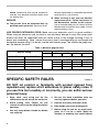
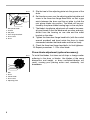
Power Planer
82 mm (3 - 1/4”)
MODEL N1900B
DOUBLE
INSULATION
I N S T R U C T I O N
M A N U A L
WARNING:
For your personal safety, READ and UNDERSTAND before using.
SAVE THESE INSTRUCTIONS FOR FUTURE REFERENCE.
w w w. m a k i t a t o o l s. c o m
SPECIFICATIONS
Model
N1900B
Planing width
82 mm (3-1/4”)
Planing depth
1 mm (1/32”)
Shiplapping depth
9 mm (11/32”)
No load speed (RPM)
15,000/min.
Overall length
290 mm (11-1/2”)
Net weight
2.5 kg (5.5 lbs)
• Manufacturer reserves the right to change specifications without notice.
• Specifications may differ from country to country.
GENERAL SAFETY RULES
USA002-2
(For All Tools)
WARNING:
Read and understand all instructions. Failure to follow all
instructions listed below, may result in electric shock, fire and/or
serious personal injury.
SAVE THESE INSTRUCTIONS
Work Area
1. Keep your work area clean and well lit.
Cluttered benches and dark areas invite accidents.
2. Do not operate power tools in explosive
atmospheres, such as in the presence of
flammable liquids, gases, or dust. Power
tools create sparks which may ignite the dust
or fumes.
2
3. Keep bystanders, children, and visitors
away while operating a power tool. Distractions can cause you to lose control.
Electrical Safety
4. Double insulated tools are equipped with
a polarized plug (one blade is wider than
the other.) This plug will fit in a polarized
outlet only one way. If the plug does not fit
fully in the outlet, reverse the plug. If it
still does not fit, contact a qualified electrician to install a polarized outlet. Do not
change the plug in any way. Double insulation
eliminates the need for the three wire
grounded power cord and grounded power
supply system.
5. Avoid body contact with grounded surfaces such as pipes, radiators, ranges and
refrigerators. There is an increased risk of
electric shock if your body is grounded.
6. Do not expose power tools to rain or wet
conditions. Water entering a power tool will
increase the risk of electric shock.
7. Do not abuse the cord. Never use the cord
to carry the tools or pull the plug from an
outlet. Keep cord away from heat, oil,
sharp edges or moving parts. Replace
damaged cords immediately. Damaged
cords increase the risk of electric shock.
8. When operating a power tool outside, use
an outdoor extension cord marked “W-A”
or “W”. These cords are rated for outdoor
use and reduce the risk of electric shock.
Personal Safety
9. Stay alert, watch what you are doing and
use common sense when operating a
power tool. Do not use tool while tired or
under the influence of drugs, alcohol, or
medication. A moment of inattention while
operating power tools may result in serious
personal injury.
10. Dress properly. Do not wear loose clothing or jewelry. Contain long hair. Keep
your hair, clothing, and gloves away from
moving parts. Loose clothes, jewelry, or long
hair can be caught in moving parts.
11. Avoid accidental starting. Be sure switch
is off before plugging in. Carrying tools with
your finger on the switch or plugging in tools
that have the switch on invites accidents.
12. Remove adjusting keys or wrenches
before turning the tool on. A wrench or a
key that is left attached to a rotating part of
the tool may result in personal injury.
13. Do not overreach. Keep proper footing
and balance at all times. Proper footing and
balance enables better control of the tool in
unexpected situations.
14. Use safety equipment. Always wear eye
protection. Dust mask, non-skid safety
shoes, hard hat, or hearing protection must
be used for appropriate conditions. Ordinary
eye or sun glasses are NOT eye protection.
Tool Use and Care
15. Use clamps or other practical way to
secure and support the workpiece to a
stable platform. Holding the work by hand or
against your body is unstable and may lead
to loss of control.
16. Do not force tool. Use the correct tool for
your application. The correct tool will do the
job better and safer at the rate for which it is
designed.
17. Do not use tool if switch does not turn it
on or off. Any tool that cannot be controlled
with the switch is dangerous and must be
repaired.
18. Disconnect the plug from the power
source before making any adjustments,
changing accessories, or storing the tool.
Such preventive safety measures reduce the
risk of starting the tool accidentally.
19. Store idle tools out of reach of children
and other untrained persons. Tools are
dangerous in the hands of untrained users.
20. Maintain tools with care. Keep cutting
tools sharp and clean. Properly maintained
tools with sharp cutting edges are less likely
to bind and are easier to control.
21. Check for misalignment or binding of
moving parts, breakage of parts, and any
other condition that may affect the tools
operation. If damaged, have the tool serviced before using. Many accidents are
caused by poorly maintained tools.
22. Use only accessories that are recommended by the manufacturer for your
3
model. Accessories that may be suitable for
one tool, may become hazardous when used
on another tool.
SERVICE
23. Tool service must be performed only by
qualified repair personnel. Service or main-
tenance performed by unqualified personnel
could result in a risk of injury.
24. When servicing a tool, use only identical
replacement parts. Follow instructions in
the Maintenance section of this manual.
Use of unauthorized parts or failure to follow
Maintenance instructions may create a risk of
electric shock or injury.
USE PROPER EXTENSION CORD: Make sure your extension cord is in good condition.
When using an extension cord, be sure to use one heavy enough to carry the current your
product will draw. An undersized cord will cause a drop in line voltage resulting in loss of
power and overheating. Table 1 shows the correct size to use depending on cord length and
nameplate ampere rating. If in doubt, use the next heavier gage. The smaller the gage number, the heavier the cord.
Table 1: Minimum gage for cord
Volts
120 V
Ampere Rating
More Than
Not More Than
0
6
10
12
6
10
12
16
25 ft.
Total length of cord in feet
50 ft.
100 ft.
150 ft.
AWG
18
18
16
14
SPECIFIC SAFETY RULES
16
16
16
12
16
14
14
12
14
12
Not Recommended
USB042-2
DO NOT let comfort or familiarity with product (gained from
repeated use) replace strict adherence to planer safety rules. If
you use this tool unsafely or incorrectly, you can suffer serious
personal injury.
1. Rags, cloth, cord, string and the like
should never be left around the work area.
4. Be sure the blade installation bolts are
securely tightened before operation.
2. Avoid cutting nails. Inspect for and
remove all nails from the workpiece before
operation.
5. Hold the tool firmly with both hands.
3. Use only sharp blades. Handle the blades
very carefully.
4
6. Keep hands away from rotating parts.
7. Before using the tool on an actual workpiece, let it run for a while. Watch for
vibration or wobbling that could indicate
poor installation or a poorly balanced
blade.
8. Make sure the blade is not contacting the
workpiece before the switch is turned on.
9. Wait until the blade attains full speed
before cutting.
10. Keep at least 200 mm (8”) away from the
tool at all times.
11. Always switch off and wait for the blades
to come to a complete stop before any
adjusting.
12. Never stick your finger into the chip chute.
Chute may jam when cutting damp wood.
Clean out chips with a stick.
13. Do not leave the tool running. Operate the
tool only when hand-held.
14. When leaving the planer, switch off and
set it with the front base up on a wooden
block, so that the blades do not contact
anything.
15. Always change both blades or covers on
the drum, otherwise the resulting imbalance will cause vibration and shorten tool
life.
16. Wait for complete run-down before putting
the tool aside.
17. Use only Makita blades specified in this
manual.
18. Some material contains chemicals which
may be toxic. Take caution to prevent dust
inhalation and skin contact. Follow material supplier safety data.
SAVE THESE INSTRUCTIONS
WARNING:
MISUSE or failure to follow the safety rules stated in this
instruction manual may cause serious personal injury.
5
FUNCTIONAL
DESCRIPTION
•
002549
CAUTION:
Always be sure that the tool is switched off and
unplugged before adjusting or checking function on the
tool.
Adjusting depth of cut
Depth of cut may be adjusted by simply turning the knob on
the front of the tool.
002553
Switch action
1
2
•
•
1. Lock button
2. Switch trigger
CAUTION:
Before plugging in the tool, always check to see that the
switch trigger actuates properly and returns to the “OFF”
position when released.
Switch can be locked in “ON” position for ease of
operator comfort during extended use. Apply caution
when locking tool in “ON” position and maintain firm
grasp on tool.
To start the tool, simply pull the switch trigger. Release the
switch trigger to stop.
For continuous operation, pull the switch trigger and then
push in the lock button.
To stop the tool from the locked position, pull the switch trigger fully, then release it.
ASSEMBLY
CAUTION:
• Always be sure that the tool is switched off and
unplugged before carrying out any work on the tool.
Removing or installing mini planer blades
CAUTION:
• Tighten the blade installation bolts carefully when
attaching the blades to the tool. A loose installation bolt
can be dangerous. Always check to see they are
tightened securely.
6
002564
1
2
•
Handle the blades very carefully. Use gloves or rags to
protect your fingers or hands when removing or installing
the blades.
•
Use only the Makita wrench provided to remove or install
the blades. Failure to do so may result in overtightening
or insufficient tightening of the installation bolts. This
could cause an injury.
1. Remove the existing blade, if the tool has been in use,
carefully clean the drum surfaces and the drum cover. To
remove the blades on the drum, unscrew the three
installation bolts with the socket wrench. The drum cover
comes off together with the blades.
1. Socket wrench
2. Bolt
002565
1
2
3
4
5
6
7
8
9
10
1. Pan head screw
2. Adjust plate
3. Planer blade locating lugs
4. Gauge plate
5. Heel of adjust plate
6. Set plate
7. Inside flank of gauge plate
8. Gauge base
9. Back side of gauge base
10.Mini planer blade
2. To install the blades, loosely attach the adjusting plate to
the set plate with the pan head screws and set the mini
planer blade on the gauge base so that the cutting edge
of the blade is perfectly flush with the inside flank of the
gauge plate.
3. Set the adjusting plate/set plate on the gauge base so
that the planer blade locating lugs on the set plate rest in
the mini planer blade groove, then press in the heel of
the adjusting plate flush with the back side of the gauge
base and tighten the pan head screws.
4. It is important that the blade sits flush with the inside
flank of the gauge plate, the planer blade locating lugs
sit in the blade groove and the heel of the adjusting plate
is flush with the back side of the gauge base. Check this
alignment carefully to ensure uniform cutting.
7
002566
6
1
5
4
3
1.
2.
3.
4.
5.
6.
2
Mini planer blade
Groove
Set plate
Hex. flange head bolt
Drum cover
Drum
5. Slip the heel of the adjusting plate into the groove of the
drum.
6. Set the drum cover over the adjusting plate/set plate and
screw in the three hex flange head bolts so that a gap
exists between the drum and the set plate to slide the
mini planer blade into position. The blade will be positioned by the planer blade locating lugs on the set plate.
7. The blade’s lengthwise adjustment will need to be manually positioned so that the blade ends are clear and equidistant from the housing on one side and the metal
bracket on the other.
8. Tighten the three hex flange head bolts (with the socket
wrench provided) and hand rotate the drum to check
clearances between the blade ends and the tool body.
9. Check the three hex flange head bolts for final tightness.
10. Repeat procedures 1 - 9 for other blade.
Planer blade adjustment (optional accessory)
002555
1
2
3
4
5
1.
2.
3.
4.
5.
8
Bolt
Drum
Planer blade
Drum cover
Adjusting plate
To install the blades, first clean out all chips or foreign matter
adhering to the drum or blades. Use blades of the same
dimensions and weight, or drum oscillation/vibration will
result, causing poor planing action and, eventually, tool
breakdown.
002556
2
3
4
5
6
7
1
8
9
1.
2.
3.
4.
5.
6.
7.
8.
9.
Inside edge of gauge plate
Blade edge
Planer blade
Adjusting plate
Screws
Heel
Back side of gauge base
Gauge plate
Gauge base
Place the blade on the gauge base so that the blade edge is
perfectly flush with the inside edge of the gauge plate. Place
the adjusting plate on the blade, then simply press in the heel
of the adjusting plate flush with the back side of the gauge
base and tighten two screws on the adjusting plate. Now slip
the heel of the adjusting plate into the drum groove, then fit
the drum cover on it. Tighten all the installation bolts evenly
and alternately with the socket wrench.
For the correct planer blade setting
Your planing surface will end up rough and uneven, unless
the blade is set properly and securely. The blade must be
mounted so that the cutting edge is absolutely level, that is,
parallel to the surface of the rear base.
Below are some examples of proper and improper settings.
EN0004-1
(A) Front base (Movable shoe)
(B) Rear base (Stationary shoe)
Correct setting
(A)
(B)
Although this side view cannot
show it, the edges of the blades
run perfectly parallel to the rear
base surface.
Cause: One or both blades fails to
have edge parallel to rear
base line.
Nicks in surface
Gouging at start
(A)
(B)
Cause: One or both blade edges
fails to protrude enough in
relation to rear base line.
(B)
Cause: One or both blade edges
protrudes too far in relation
to rear base line.
Gouging at end
(A)
9
002570
Nozzle assembly (optional accessory)
Use of the special nozzle assembly will minimize chip scatter, making for a cleaner work area.
1
1. Nozzle assembly
002571
1
2
The nozzle assembly may be attached after the chip cover
on the tool body is removed. When slipping on the assembly,
fit the pin on it into the rear cover hole. Use the chip cover
screws to fasten it in place.
3
1. Chip cover screw
2. Chip cover
3. Hole
002548
1
Dust bag (optional accessory)
The use of the dust bag makes cutting operations clean and
dust collection easy. To attach the dust bag, first remove the
chip cover and then install the dust bag assembly.
For the best results, empty the dust bag when it becomes
about half full. Remove the dust bag from the tool and pull
out the fastener.
1. Dust bag assembly
10
OPERATION
002579
2
1
1. End
2. Start
002580
Planing operation
First, rest the tool front base flat upon the workpiece surface
without the blades making any contact. Switch on and wait
until the blades attain full speed. Then move the tool gently
forward. Apply pressure on the front of tool at the start of
planing, and at the back at the end of planing. Planing will be
easier if you incline the workpiece in stationary fashion, so
that you can plane somewhat downhill.
The speed and depth of cut determine the kind of finish. The
power planer keeps cutting at a speed that will not result in
jamming by chips. For rough cutting, the depth of cut can be
increased, while for a good finish you should reduce the
depth of cut and advance the tool more slowly.
Shiplapping (Rabbeting)
To make a stepped cut as shown in the figure, use the edge
fence (guide rule).
002582
Draw a cutting line on the workpiece. Insert the edge fence
into the hole in the front of the tool. Align the blade edge with
the cutting line.
002583
Adjust the edge fence until it comes in contact with the side
of the workpiece, then secure it by tightening the screw.
1
2
1. Blade edge
2. Cutting line
When planing, move the tool with the edge fence flush with
the side of the workpiece. Otherwise uneven planing may
result.
1
Maximum shiplapping (rabbeting) depth is 9 mm (11/32”).
2
1. Screw
2. Edge fence
11
002584
You may wish to add to the length of the fence by attaching
an extra piece of wood. Convenient holes are provided in the
fence for this purpose, and also for attaching an extension
guide (optional accessory).
003634
Chamfering
To make a chamfering cut as shown in the figure, align the
“V” groove in the front base with the edge of the workpiece
and plane it.
003634
1
1. “V” groove
MAINTENANCE
•
CAUTION:
Always be sure that the tool is switched off and
unplugged before attempting to perform inspection or
maintenance.
Sharpening the planer blades (optional accessory)
002588
1
1. Sharpening holder
12
Always keep your blades sharp for the best performance
possible. Use the sharpening holder (optional accessory) to
remove nicks and produce a fine edge.
002589
1
5
2
4
3
1.
2.
3.
4.
5.
First, loosen the two wing nuts on the holder and insert the
blades (A) and (B), so that they contact the sides (C) and (D).
Then tighten the wing nuts.
Wing nut
Blade (A)
Blade (B)
Side (D)
Side (C)
002590
Immerse the dressing stone in water for 2 or 3 minutes
before sharpening. Hold the holder so that the blades both
contact the dressing stone for simultaneous sharpening at
the same angle.
001145
Replacing carbon brushes
Remove and check the carbon brushes regularly. Replace
when they wear down to the limit mark. Keep the carbon
brushes clean and free to slip in the holders. Both carbon
brushes should be replaced at the same time. Use only identical carbon brushes.
1
1. Limit mark
002597
Use a screwdriver to remove the chip cover.
1
2
1. Chip cover
2. Screwdriver
13
002598
1
2
Use a screwdriver to remove the brush holder caps. Take out
the worn carbon brushes, insert the new ones and secure
the brush holder caps.
To maintain product SAFETY and RELIABILITY, repairs, any
other maintenance or adjustment should be performed by
Makita Authorized or Factory Service Centers, always using
Makita replacement parts.
1. Brush holder cap
2. Screwdriver
ACCESSORIES
•
CAUTION:
These accessories or attachments are recommended for
use with your Makita tool specified in this manual. The
use of any other accessories or attachments might
present a risk of injury to persons. Only use accessory
or attachment for its stated purpose.
If you need any assistance for more details regarding these
accessories, ask your local Makita service center.
14
•
High-speed steel Planer blade
•
Tungsten-carbide Planer blade (For longer blade life)
•
Mini planer blade
•
Sharpening holder assembly
•
Blade gauge
•
Set plates set
•
Edge fence (Guide rule)
•
Extension guide set
•
Dressing stone
•
Nozzle assembly
•
Dust bag assembly
•
Socket wrench
•
Plastic carrying case
Memo
15
Memo
16
Cut
First-Class
Postage
Required
Post Office will
not deliver
without proper
postage.
Makita U.S.A., Inc.
14930 Northam Street
La Mirada, CA 90638-5753
Fold
17
MAIL THIS PORTION
Your answers to the following questions are appreciated.
1. This product was purchased from:
Home Center
3. How did you learn about this product:
Magazine
Radio
Hardware/Lumber Store
From Dealer
Exhibition
Tool Distributor
Newspaper
From Friend
Industrial Supply
Store Display
Previous Usage
Construction Supply
Catalog
Other (
Other (
)
2. Use of the product is intended for:
)
4. Most favored points are:
Construction Trade
Design
Repair Service
Industrial Maintenance
Features
Durability
Home Maintenance
Size
Power
Hobby
Price
Other (
Other (
)
)
Makita Brand
5. Any comments:
Paste
MODEL NO.
DAY
YEAR
SERIAL NO.
SEX
STATUS
INTL.
LAST NAME / COMPANY NAME
Married Single
M
F
STREET ADRESS
Paste
MONTH
Paste
Paste
Paste
Paste
DATE PURCHASED
Under 19
AREA
CODE
PHONE
20-29
30-39
Paste
AGE:
ZIP CODE
40-49
50-60
Over 60
Paste
Paste
STATE
Paste
CITY
Paste
Paste
BE SURE TO COMPLETE THE CUSTOMER’S PORTION OF THIS FORM AND RETAIN FOR YOUR RECORDS.
Please return this portion by facsimile or mail.
18
Facsimile No: (714) 522-8133
Paste
Paste
Paste
Paste
Paste
Paste
Paste
Paste
FACTORY SERVICE CENTERS
1-800-4-MAKITA
RETAIN THIS PORTION FOR YOUR RECORDS
ARIZONA
3707 E. Broadway Rd., Ste. 6
Phoenix, AZ 85040
(602) 437-2850
FLORIDA
750 East Sample Road
Pompano Beach, FL 33064
(954) 781-6333
MISSOURI
9876 Watson Road
St. Louis, MO 63126-2221
(314) 909-9889
PENNSYLVANIA
1704 Babcock Blvd.
Pittsburgh, PA 15209
(412) 822-7370
CALIFORNIA
41850 Christy St.
Fremont, CA 94538-5107
(510) 657-9881
GEORGIA
4680 River Green Parkway NW
Duluth, GA 30096
(770) 476-8911
NEBRASKA
4129 S. 84th St.
Omaha, NE 68127
(402) 597-2925
PUERTO RICO
200 Guayama St.
Hato Rey, PR 00917
(787) 250-8776
ILLINOIS
1450 Feehanville Dr.
Mt. Prospect, IL 60056-6011
(847) 297-3100
NEVADA
3375 S. Decatur Blvd.
Suites. 22 - 24
Las Vegas, NV 89102
(702) 368-4277
TENNESSEE
1120 Elm Hill P.
Suile 170 Nashville, TN 372
(615) 248-3321
14930 Northam St.
La Mirada, CA 90638-5753
(714) 522-8088
1970 Fulton Avenue
Sacramento, CA 95825
(916) 482-5197
7674 Clairemont Mesa Blvd.
San Diego, CA 92111
(858) 278-4471
16735 Saticoy St., Ste. 105
Van Nuys, CA 91406
(818) 782-2440
COLORADO
11839 E. 51st Ave.
Denver, CO 80239-2709
(303) 371-2850
MARYLAND
7397 Washington Boulevard,
Suite 104 Elkridge, MD 21075
(410) 796-4401
MASSACHUSETTS
232 Providence Hwy.
Westwood, MA 02090
(781) 461-9754
MINNESOTA
6427 Penn Ave. South
Richfield, MN 55423
(612) 869-5199
NEW JERSEY
251 Herrod Blvd.
Dayton, NJ 08810-1539
(609) 655-1212
NEW YORK
4917 Genessee Street
Cheektowaga, NY 14225
(716) 685-9503
OREGON
828 19th Avenue, N.W.
Portland, OR 97209
(503) 222-1823
TEXAS
12801 Stemmons Fwy Ste. 809
Farmers Branch, TX 75234
(972) 243-1150
12701 Directors Dr.
Stafford, TX 77477-3701
(281) 565-8665
3453 IH-35 North, Ste. 101
San Antonio, TX 78219
(210) 228-0676
WISCONSIN
Lincoln Plaza Shopping Ctr.
2245 S. 108th St. West Allis, WI
53227
(414) 541-4776
CUSTOMER’S RECORD
When you need service: Send
complete tool (prepaid) to one
of the Makita Factory Service
Centers listed, or to an Authorized
Makita Service Center. Be sure
to attach a letter to the outside of
the carton detailing the problem
with your tool.
Date Purchased
Dealer’s Name & Address
Model No.
Serial No.
19
WARNING
Some dust created by power sanding, sawing, grinding, drilling, and other
construction activities contains chemicals known to the State of California
to cause cancer, birth defects or other reproductive harm. Some examples
of these chemicals are:
• lead from lead-based paints,
• crystalline silica from bricks and cement and other masonry products, and
• arsenic and chromium from chemically-treated lumber.
Your risk from these exposures varies, depending on how often you do this
type of work. To reduce your exposure to these chemicals: work in a well
ventilated area, and work with approved safety equipment, such as those
dust masks that are specially designed to filter out microscopic particles.
MAKITA LIMITED ONE YEAR WARRANTY
Warranty Policy
Every Makita tool is thoroughly inspected and tested before leaving the factory. It is warranted to be free of
defects from workmanship and materials for the period of ONE YEAR from the date of original purchase.
Should any trouble develop during this one year period, return the COMPLETE tool, freight prepaid, to one of
Makita’s Factory or Authorized Service Centers. If inspection shows the trouble is caused by defective
workmanship or material, Makita will repair (or at our option, replace) without charge.
This Warranty does not apply where:
• repairs have been made or attempted by others:
• repairs are required because of normal wear and tear:
• the tool has been abused, misused or improperly maintained:
• alterations have been made to the tool.
IN NO EVENT SHALL MAKITA BE LIABLE FOR ANY INDIRECT, INCIDENTAL OR CONSEQUENTIAL
DAMAGES FROM THE SALE OR USE OF THE PRODUCT. THIS DISCLAIMER APPLIES BOTH DURING
AND AFTER THE TERM OF THIS WARRANTY.
MAKITA DISCLAIMS LIABILITY FOR ANY IMPLIED WARRANTIES, INCLUDING IMPLIED WARRANTIES OF
“MERCHANTABILITY” AND “FITNESS FOR A SPECIFIC PURPOSE,” AFTER THE ONE YEAR TERM OF THIS
WARRANTY.
This Warranty gives you specific legal rights, and you may also have other rights which vary from state to state.
Some states do not allow the exclusion or limitation of incidental or consequential damages, so the above
limitation or exclusion may not apply to you. Some states do not allow limitation on how long an implied
warranty lasts, so the above limitation may not apply to you.
Makita Corporation of America
2650 Buford Hwy., Buford, GA 30518
883185I067