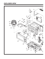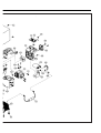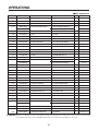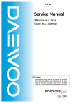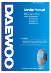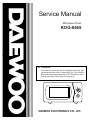
1
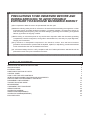
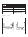
Service Manual
Microwave Oven
KOG-8465
✔ Caution
: In this Manual, some parts can be changed for improving, their
performance without notice in the parts list. So, if you need the
latest parts information,please refer to PPL(Parts Price List) in
Service Information Center (http://svc.dwe.co.kr).
Power
1
2
3
6
4
40 50 6
0
0
30
Timer
5
7
8
9
10
20
DAEWOO ELECTRONICS CO., LTD.
PRECAUTIONS TO BE OBSERVED BEFORE AND
DURING SERVICING TO AVOID POSSIBLE
EXPOSURE TO EXCESSIVE MICROWAVE ENERGY
(a) Do not operate or allow the oven to be operated with the door open.
(b) Make the following safety checks on all ovens to be serviced before activating the magnetron or other
microwave source, and make repairs as necessary: (1) Interlock operation, (2) proper door closing, (3)
seal and sealing surfaces (arcing, wear, and other damage), (4) damage to or loosening of hinges and
latches, (5) evidence of dropping or abuse.
(c) Before turning on microwave power for any service test or inspection within the microwave generating
compartments, check the magnetron, wave guide or transmission line, and cavity for proper alignment,
integrity, and connections.
(d) Any defective or misadjusted components in the interlock, monitor, door seal and microwave
generation and transmission systems shall be repaired, replaced, or adjusted by procedures described
in this manual before the oven is released to the owner.
(e) A microwave leakage check to verify compliance with the Federal performance standard should be
performed on each oven prior to release to the owner.
TABLE OF CONTENTS
PROPER USE AND SERVICE PRECAUTIONS
SPECIFICATIONS
EXTERNAL VIEWS
NAMES AND FUNCTION OF PARTS
CONTROL PANEL
HOW TO SET THE OVEN CONTROLS
INTERLOCK MECHANISM FUNCTIONS AND ADJUSTMENTS
PRECAUTIONS FOR DISASSEMBLY AND REPAIR
DISASSEMBLY AND ASSEMBLY
TROUBLE SHOOTING GUIDE
MEASUREMENT
COMPONENT TEST PROCEDURE
WIRING DIAGRAM
SCHEMATIC DIAGRAM
WIRING DIAGRAM(GERMANY)
SCHEMATIC DIAGRAM(GERMANY)
EXPLODED VIEW
2
3
5
5
6
7
8
11
13
14
21
25
27
28
29
31
32
34
PROPER USE AND SERVICE PRECAUTIONS
CAUTION : This Device is to be Serviced Only by Properly Qualified Service Personnel. Consult the Service
Manual for Proper Service Procedures to Assure Continued Safety Operation and for Precautions
to be Taken to Avoid Possible Exposure to Excessive Microwave Energy.
1. For Safe Operation
Damage that allows the microwave energy (that cooks or heats the food) to escape will result in poor cooking and
may cause serious bodily injury to the operator.
IF ANY OF THE FOLLOWING CONDITIONS EXIST, OPERATOR MUST NOT USE THE APPLIANCE.
(Only a trained service personnel should make repairs.)
1)
2)
3)
4)
5)
A broken door hinge.
A broken door viewing screen.
A broken front panel, oven cavity.
A loosened door lock.
A broken door lock.
The door gasket plate and oven cavity surface must be kept clean.
No grease, soil or spatter should be allowed to build up on these surfaces or inside the oven.
DO NOT ATTEMPT TO OPERATE THIS APPLIANCE WITH THE DOOR OPEN. The microwave oven has
concealed switches to make sure the power is turned off when the door is opened. Do not attempt to defeat them.
DO NOT ATTEMPT TO SERVICE THIS APPLIANCE UNTIL YOU HAVE READ THIS SERVICE MANUAL.
2. Correct Installation
1) This microwave oven weighs 18 kg(40lbs.) and must be placed on a horizontal base strong enough to support
this weight.
2) The oven should be placed as far from high temperature source and vapour as possible.
3) The power supply cord is about 1.6m (5.25ft) long. Earthing is required when connecting the power source.
4) Power consumption of this oven is approximately 2.8 kw. It is suggested that the unit is operated on such power
line(about 12 amperes) that can provide more power than this rating.
5) Object must not be placed on the top enclosure so as not to obstruct air flow for ventilation.
CAUTION
MICROWAVE RADIATION
PERSONNEL SHOULD NOT BE EXPOSED TO THE MICROWAVE ENERGY WHICH MAY RADIATE
FROM THE MAGNETRON OR OTHER MICROWAVE GENERATING DEVICE IF IT IS IMPROPERLY
USED OR CONNECTED. ALL INPUT AND OUTPUT MICROWAVE CONNECTIONS, WAVEGUIDE,
FLANGES AND GASKETS MUST BE SECURE. NEVER OPERATE THE DEVICE WITHOUT A
MICROWAVE ENERGY ABSORBING LOAD ATTACHED. NEVER LOOK INTO AN OPEN WAVEGUIDE
OR ANTENNA WHILE THE DEVICE IS ENERGIZED
3
IMPORTANT
The wires in this mains lead coloured in accordance with the following code.
Green-and-yellow
: Earth
Blue
: Neutral
Brown
: Live
As the colours of the wires in the mains lead of this appliance may not correspond with the coloured markings
identifying the terminals in your plug, proceed as follows:
The wire which is coloured green-and-yellow must be connected to the terminal in the plug which is marked
with the letter ‘E’ or by earth symbol or green-and-yellow.
The wire which is coloured blue must be connected to the terminal which is marked with the letter ‘N’ or
coloured black.
The wire which is coloured brown must be connected to the terminal which is marked with the letter ‘L’ or
coloured red.
NOTE : This oven is designed for counter-top use only.
4
SPECIFICATIONS
Power Supply
230V~, 50Hz
240V~, 50Hz(U.K)
Power Consumption
1,450 W
1,500W
Output Power
900W (IEC 705)
900W (IEC 705)
Frequency
2,450 MHz
2,450 MHz
Grill power consumption
1,400 W
1,500W
Simultaneous Heating Power Consumption
2,800 W
2,950 W
Outside Dimensions (W X H X D)
501 X 319 X 389 mm (19.7 X 12.6 X 15.3 in.)
Cavity Dimensions (W X H X D)
310 X 229 X 330 mm (12.2 X 9.0X 13.0 in.)
Net Weight
Approx. 18 kg (40 Ibs.)
Timer
60 min. Dual
Select Function
Microwave/Grill/Simultaneous Heating
Microwave Power Level
High/Med High/Med/Defrost/Low
Microwave
(900W) (725W) (520W) (310W) (165W)
Simultaneous heating Level
3-Levles( Grill+M/W 3-Power levels)
* Specifications subject to change without notice.
EXTERNAL VIEWS
5
NAMES AND FUNCTION OF PARTS
¤ DOOR SEAL
Door seal maintains the microwave within the
oven cavity and prevents microwave leakage.
¤ CONTROL PANEL
¤ GLASS TURN -TABLE TRAY
Rotates during cooking and ensure even
distribution of Microwaves. It can also be used as
a cooking utensil.
¤Ł DOOR HOOK
When door is closed, it will autoamtically lock shut.
If door is opened while oven is operating,
magnetron tube will immediately stop operating.
¤ OVEN FRONT PLATE
¤ ROLLER GUIDE
This must be always used for cooking together
with the glass turn-table tray. Use a mild
detergent, water and a soft cloth to clean the
roller guide.
¤Ø DOOR SCREEN
Allows viewing of food. Microwave cannot pass
through perforations in screen.
¤Œ GRILL HEATER
Turns on when grill and simultaneous cooking is
selected.
¤æ COUPLER
This fits over the shaft in the center of the oven’s
cavity floor.
This is to remain in the oven for all cooking.
¤º OVEN LAMP
Automatically turns on during oven operating.
¤ SAFETY INTERLOCK SYSTEM
6
CONTROL PANEL
POWER OR FUNCTION SELECT KNOB
- Used to select a microwave power level in M/W,
GRILL or SIMUL. cooking.
Power
- Used to select a function before the cooking.
1) M/W oven-used to heat food with
microwave.
2) GRILL-Used to browning food with grill
heater.
3) SIMUL. - used to simultaneous cooking with
microwave and grill heater.
0
1
2
3
40 50 6
0
Timer
4
- Used in setting cooking time for all functions.
6
30
5
TIMER KNOB
7
8
NOTE :
When setting TIMER for less than 1
minute, turn the TIMER past 1 minute
and then return to correct timing.
7
9
10
20
HOW TO SET THE OVEN CONTROLS
NOTE :
¡ Be sure to read the cookbook’s introduction before operating the oven.
¡ Also remember to read this operating instruction for proper safety information and instruction before using
the oven.
¡ See the cookbook for specific recipes.
¡ Prior to setting the controls, place one cup of water in the oven, in a heat-proof glass measuring cup, for
testing purposes.
¡ You may open the door while the oven is operating.
¡ As soon as the door is opened, the safety mechanisms stop power.
¡ To continue cooking, close door, then the oven is operated.
¡ If you wish to change the time during cooking, simply adjust the TIMER to desired minutes.
¡ When time has elapsed, a bell will ring and the oven will turn off.
1. MICROWAVE DEFROST
• This oven has 5-power levels in microwave cooking.
• You can select these levels by POWER knob.
1. place food inside oven.
2. Set POWER knob to appropriate M/W power level position.
3. Set TIMER knob to the cooking time.
SYMBOL
M/W POWER LEVEL
OUTPUT POWER
LOW
165W
DEFROST
310W
MEDIUM
520W
MED. HIGH
725W
HIGH
900W
NOTE : Output power refer to a value of reference.
8
2. GRILL COOKING
¥ Grilling in this oven is similar to conventional broiling.
¥ There is no need to preheat the oven for griling.
1. Place food on the Metal Rack, and set it on the Tray.
2. Set POWER knob to GRILL position.
3. Set TIMER knob to the cooking time.
EXAMPLE : To Grill hamburgers, steaks, kabobs, etc. use the trays this way:
To use :
• Place food on Metal Rack.
• Place the Metal Rack directly on the
Turntable.
9
2. COMBINATION COOKING
¥ This oven has 3-cooking levels in SIMUL-COOKING.
¥ You can select these levels by POWER knob.
(COMBI 1)
Grill
+
M/W Low
(COMBI 2)
Grill
+
M/W Med Low
(COMBI 3)
Grill
+
M/W Med
1. Place food on the Metal Rack or Tray.
2. Set POWER knob to SIMUL position.
3. Set TIMER knob to the cooking time.
• To prevent the oven operating with the door open, this oven is fitted with safety door interlock switches.
If you wish to inspect the food during the cooking time, simply open the door.
The oven will automatically stop the cooking.
• To continue cooking, close the door.
• If you wish to stop the cook during the cooking, simply turn the timer knob to the point “OFF”.
Cooking time can be reset at any time during cycle by turing the timer knob.
• Do not let the timer continue to oeprate after removing food.
10
INTERLOCK MECHANISM FUNCTIONS AND ADJUSTMENTS
The door lock mechanism is a device which has been specially designed to completely eliminate micreowave
radiation when the door is opened during operation, and thus to perfectly prevent the danger resulting from the
leakage of microwave.
(1) Primary interlock switch
When the door is closed, the hook will lock the oven door.
If the door is not closed properly, the oven will not operate.
When the door is closed, the hook pushes the lever downward.
The lever presses the button of the primary interlock switch to bring it under ‘ON’ condition.
Adjustment 1
When the door is closed, the switch button is pushed
by the hook.
The movement of the switch button should exceed 1.2
mm measured at the top of the button.
11
(2) Secondary interlock switch, monitor interlock switch
When the door is closed, the hook pushes the lever lock forward, and the lever presses the button of the interlock
monitor switch to bring it under ‘OFF’ condition. Simultaneously, the lever lock presses the button on the
secondary interlock switch to bring it under ‘ON’ condition.
Monitor interlock s/w
Lever hook
Door open monitor s/w
Hook
Lever lock
Spring hook lever
Adjustment 2
Interlock monitor switch
When the door is closed, the monitor switch should be opened before other switches closed.
When the door is opened, the monitor switch should be closed after other switches opened.
Secondary interlock switch
The movement of the switch button should exceed 1.2mm measured at the top of the button.
Adjustment step:
a) Loosen the two mounting screws.
b) Adjust the interlock switch assembly position.
c) Confirm the gap(1.2mm) described above.
d) Make sure that the latch lever moves smoothly after adjustment is completed
e) Completely tighten the two mounting screws.
12
PRECAUTIONS FOR DISASSEMBLY AND REPAIR
- Cautions to be observed when trouble shooting.
Unlike many other appliances, the microwave oven is high-voltage, high-current equipment. It is completely safe
during normal operation. However, carelessness in servicing the oven can result in an electric shock or possible
danger from a short circuit.
You are asked to observe the following precautions carefully.
(1) Always remove the power plug from the outlet before servicing.
(2) use an insulated screwdriver and wear rubber gloves when servicing the high voltage side.
(3) Warning about the electric charge in the high voltage capacitor. When inspecting and repairing the high voltage
side, always short the capacitor terminals and make sure of discharge.
1. Check the earthing.
Do not operate on a 2-wire extension cord. The
microwave oven is designed to be used when earthed.
It is imperative, therefore, to makes sure it is earthed
properly before begining repair work.
2. Warning about the electric charge in the
high voltage capacitor. (Refer to Fig. 1)
For about 30 seconds after the operation stops, electric
charge remains in the high voltage capacitor. When
replacing or checking parts, short between oven
chassis and the negative high terminal of the high
voltage capacitor, by using a properly insulated screw
driver to discharge.
Fig.1
(4) When the fuse(normal blow type) is blown out due to the operation of the monitor switch; replace primary,
secondary interlock switch and monitor switch.
Refer 11~12 page for the necessary adjustment.
(5) After repair or replacement of parts, make sure that the screws are properly tightened and all electrical
connections are tightened.
(6) Do not operate without cabinet.
CAUTION : Service personnel should remove their watches whenever working close to or repairing the
magnetron.
WARNING: When servicing the appliance, care is required when touching or replacing high potential parts due
to electrical shock or exposure of microwave energy. These parts are as follows-H.V. transformer,
Magnetron, H.V. Capacitor, H.V. Diode.
13
DISASSEMBLY AND ASSEMBLY
1. To remove cabinet (Refer to Fig. 2)
1) Remove four screws on cabinet back.
2) Push the cabinet backward.
Fig. 2
2. To remove parts of guide wind assembly
(Refer to Fig.3)
1) Release the earth screw F57 .
2) Remove the noise-filter F52 to the guide wind F42 .
3) Pull the fan F45 to the motor shaft.
4) Release two screws F44 which secure the motor shaded pole F43 .
5) Remove the motor shaded pole.
6) Release a screw F48 which secure the holder capacitor F47 .
7) Remove the holder capacitor and capacitor F46 to the guide wind.
8) Remove the diode H.V F49 .
9) Reverse the above steps for reassembly.
F53
F57
F52
F44
F42
F45
F43
F49
F46
F48
F47
Fig. 3
14
3. To remove lamp. (Refer to Fig. 4)
F37
1) Remove a screw F37 holding lamp F36 to the
guide air F34 .
2) Remove the lamp.
3) Reverse the above steps for reassembly.
F36
F34
Fig. 4
4. To remove H.V. Transformer
(Refer to Fig. 5)
F21
1) Remove four screws F22 which secure the H.V.
Transformer bracket to the base plate.
2) Remove the H.V. Transformer F21 .
F22
Fig. 5
HIgh voltage circuit wiring
H.V. Capacitor
Magnetron
H.V. Diode
H.V. Trans
15
H.V. Fuse
5. To remove magnetron and magnetron thermostat. (Refer to Fig. 6)
1) Remove two screws F26 which secure the thermostat F25.
2) Remove the thermostat.
3) Remove three screws F24 which secure the magnetron F23 .
4) Remove the magnetron.
5) Reverse the above steps for reassembly.
F26
F25
F23
F24
Fig. 6
CAUTION : Never install the magnetron without the metallic gasket plate which is packed with each
magnetron to prevent microwave leakage. Whenever repair work is carried out on magnetron,
check the microwave leakage. It shall not exceed 4mW/cm2 for a fully assembled oven with door
normally closed.
Metallic
gasket
plate
Magnetron
antenna
Wave guide
Cooling fin
Magnetron
Metallic gasket plate
Filament
terminal
16
magnetron antenna
✔ Caution: In this Service Manual, some parts can be changed for improving, their performance without notice in the parts list. So, if you need the
latest parts information, please refer to PPL(Parts Price List) in Service information Center(http://svc.dwe.co.kr)
6. To remove parts of control panel assembly (Refer to Fig. 7.8)
1) Remove a screw holding control panel assembly to the oven
front plate. At the same time, draw forward the control panel
assembly from oven front plate.
2) Remove two screws B11 which secure the timer assembly B10 .
3) Remove the timer assmebly B10 .
4) Pull out the knob B3 from the timer assembly B10 .
5) Pull out the coupler timer B9 from the timer assembly B10 .
6) Remove a screw B13 which secure the sw MICRO B12 .
7) Pull out the sw MICRO B12 from the control panel B1 .
8) Remove a screw B8 which secure the coupler VPC knob B7 .
9) Pull out the coupler VPC knob B7 and knob VPC B2 from the
control panel B1 .
10) Remove the spring flat B6 .
11) Remove a screw B5 which secure the sw MICRO B4 .
12) Pull out the sw MICRO B4 from the control panel B1 .
13) Reverse the above steps for reassembly.
Fig. 7
B5
B8
B6
B10
B4
B1
B11
B13
B9
B2
B12
B3
CONTROL PANEL AS : 3516710620
REF.NO.
B1
B2
B3
B4
B5
B6
B7
B8
B9
B10
B11
B12
B13
PART CODE
3516705830
3513403900
3513401220
4415A66600
7121301611
3515101600
3517401200
7S312X40A1
3517401100
3518204900
7S341W40B1
4415A17352
7121301611
PART NAME
CONTROL-PANEL
KNOB VPC
KNOB
SW MICRO
SCREW TAPPING
SPRING FLAT
COUPLER VPC KNOB
SCREW SPECIAL
COUPLER TIMER
TIMER
SCREW SPECIAL
SW MICRO
SCREW TAPPING
DESCRIPTION
Q’TY
ABS
1
ABS
1
ABS
1
VP-532A-OF SPNC #187
1
T2S PAN 3X16 MFZN
1
SUS-301 T0.5
1
POM
1
T1 TRS 4X10 SE MFZN
1
POM
1
KN60MKD11E-P
1
T2S PAN 4X12 PW SE MFZN 2
VP-533A-OF SPNO #187 1
T2S PAN 3X16 MFZN
1
17
Fig. 8
REMARK
✔ Caution: In this Service Manual, some parts can be changed for improving, their performance without notice in the parts list. So, if you need the
latest parts information, please refer to PPL(Parts Price List) in Service information Center(http://svc.dwe.co.kr)
7. To remove door assembly (Refer to Fig. 9)
F20
1) Remove two bolts F19 and two nuts F20 which secure to hinge.
2) Remove door assembly A00 .
3) Remove door above for reassembly taking case to replace fixing glue.
A00
8. To remove door parts. (Refer to Fig. 10)
1) Remove the frame door A9 and barrier-screen
2) Remove the absorber microwave A7 .
3) Pull the two fixture hook A5 .
4) Remove the spring hook A6 .
5) Remove two hooks A3 , and lever hook A4 .
A8
.
F19
Fig.9
DOOR AS : 3511704420
REF.NO.
A1
A2
A3
A4
A5
A6
A7
A8
A9
PART CODE
3511704600
3517001800
3513100600
4413A44001
4413A40052
441G448071
3510100300
3517003600
3512203000
PART NAME
DOOR PAINTING AS
BARRIER-SCREEN *I
HOOK
LEVER HOOK AS
FIXTURE HOOK
SPRING HOOK
ABSORBER MICROWAVE
BARRIER-SCREEN *O
FRAME DOOR
18
DESCRIPTION
Q’TY
1
TEMPERED GLASS 3.2T 1
POM
2
KOR-640
1
SWRM3 Ø5.5XL12.5
2
SWPA80
1
PAI+FERRITE
1
GLASS 3.0T
1
ABS
1
Fig. 10
REMARK
9. Method to reduce the gap between the door seal and the oven front surface.
(1) To reduce gap located on part ‘A’.
1) Loosen a Hex Bolt on top door hinge, then push
the door to contact the door seal to oven front
surface.
2) Tighten a Hex Bolt.
(2) To reduce gap located on part ‘B’.
1) Loosen a Hex Bolt on bottom hingle, then push
the door to contact the door seal to oven front
surface.
2) Tighten a Hex Bolt.
(3) To reduce gap located on part ‘C’
1) Remove the cabinet.
2) Loosen a screw on interlock switch assembly located bottom of oven body.
3) Draw the interlock switch assembly inward as possible to engage with hook on the door bottom.
4) Tighten a screw.
(4) To reduce gap located on part ‘D’.
1) Remove the cabinet.
2) Loosen a screw on interlock switch assembly located top of oven body.
3) and (4) are same as step (3).
Door hook
(under)
Interlock monitor
switch
Mounting screw (Top)
Door hook
(upper)
Primary
interlock switch
Mounting screw
(bottom)
NOTE : Small gap may be acceptable if the microwave leakage does not exceed 1mW/cm2.
NOTE : The door on a microwave oven is designed to act as an electronic seal preventing the leakage of
microwave energy from the oven cavity during the cook cycle, This function does not require that the
door be air-tight, moisture (condensation) - tight or light-tight. Therefore, the occasional appearance of
moisture, light or the sensing of gentle warm air movement around the oven door is not abnormal and
do not of themselves, indicate a leakage of microwave energy from the oven cavity. If such were the
case, your oven could not be equipped with a vent, the very purpose of which is to exhaust the vaporladen air from the oven cavity.
19
10. To remove tray motor. (Refer to Fig. 11)
1) Cut the tray motor cover parts from the base
plate (Refer to Fig 11, 12).
2) Remove the tray motor cover.
3) Remove two screws F12 which secure the tray
motor F11 to tray motor bracket.
4) Remove the tray motor.
F11
F12
Fig. 11
(Front)
(Bottom)
Slit
Nipper
File
Fig. 12
20
11. To remove grill heater assembly (Refer to Fig. 13)
1) Release three hex nuts F10 holding the Grill Heater Assembly
2) Remove Grill heater Assembly.
F9
to top and side plate.
F10
F9
Fig. 13
TROUBLE SHOOTING GUIDE
Following the procedure below to check if the oven is defective or not.
1.
2.
3.
4.
Check earthing before fault finding.
Be careful of the high voltage circuit.
Discharge the high voltage capacitor.
When checking the continuity of the switches, fuse or high voltage transformer, disconnect one lead wire from
these parts and check continuity with the AC plug removed. To do otherwise may result in a false reading or
damage to your meter.
NOTE : When electric parts are checked or replaced, be sure the power cord is not inserted the wall outlet.
Check wire harness, wiring, and connection of the terminals, and power cord before check the parts
listed below.
21
(TROUBLE 1) Oven does not operate at all; any inputs can not be accepted
Condition
Check
Result
Cause
Fuse blows
Check continuity
of interlock monitor
switch with door closed
(COM¡ŒNC)
(COM¡ŒNC)
Malfunction of
interlock monitor
switch
Replace
Check continuity
of both primary and
secondary interlock
switch with door closed
No
Continuity
Malfunction of
interlock switch
Replace
Shorted contacts
of primary
interlock switch
Replace
Check continuity of
primary interlock switch
contact with door partially
open until interlock
monitor switch contact
close (COM¡ŒNC close)
Outlet has
proper voltage.
Fuse does
not blow
Continuity
(COM¡ŒNC)
Remedy
Note 1.
No
Continuity
Note 1.
Continuity
Continuity
Note 1.
Check continuity
both magnetron and
heater thermostat
No
Continuity
Defective
magnetron and
heater thermostat
Replace
check continuity of noise
filter board
No
Continuity
Defective line
filter board
Replace
Check continuity
of power supply cord
No
Continuity
Open power
supply cord
Replace
NOTE 1 : All these switches must be replaced at the same time, please refer to page 11 and 12 for adjustment
instructions.
22
(TROUBEL 2) Heater does not heat (Food will not become hot).
Condition
Check
Result
Grill heater
does not heat
Check continuity
of primary
interlock switch
No
Continuty
Malfunction of
primary interlock
switch
Check continuity
of heater select switch
and timer switch
No
Continuity
Defective timer
ass’y
Check continuity
of heater
thermostat
No
Continuity
Chech continuity of
secondary interlock
switch
No
continuity
Check continuity of
heater
No
continuity
23
Cause
Remedy
Adjust or
replace
Replace the
timer ass’y
Defective heater
thermostat
Replace the
heater
thermostat
Malfunction of
secondary
interlock switch
Adjust or
replace
Defective heater
Replace the
heater
(TROUBLE 3) No microwave oscillation even though fan motor rotates.
Condition
Fuse blows
No microwave
oscillation
Check
Check continuity
of high voltage fuse
Result
(COM¡ŒNC)
Cause
Remedy
No
Continuity
Replace high voltage fuse
Check continuity
of high voltage capacitor
terminals with wires
removed
Continuity
Defective high
voltage
transformer
Replace
Check continuity of high
voltage recitifier in
forword and backward
direction with DC megger
Continuity
in backward
direction
Defective high
voltage rectifier
Replace
Connect megger
leads to magnetron
terminal and magnetron
body
Continuity
Defective
magnetron
Replace
Check resistance of
primary and secondary
coil of high voltage
transformer
0 Ω or ∞
Defective high
voltage
transfromer
Replace
Check continuity
of magnetron heater
with wires removed
No
Continuity
Check continuity
of filament terminal
of high voltage
transformer
No
Continuity
Defective high
voltage
transfromer
Replace
No
Continuity
Defective timer
ass’y
Replace
Check continuity of
microwave select switch
24
Defective
magnetron
Replace
MEASUREMENT
1. Microwave Output Power
CAUTION :
1-1. Standard Method
Microwave output power can be checked by indirectly
measuring the temperature rise of a certain amount of
water exposed to the microwave as directed below.
1) Microwave power output measurement is made with
the microwave oven supplied at rated voltage and
operated at its maximum microwave power setting
with a load of 1,000¡ 5cc of potable water.
2) The water is contained in a cylindrical borosilicate
glass vessel having a maximum material thickness
of 3 mm and an outside diameter of approximately
190 mm.
3) The oven and the empty vessel are at ambient
temperature prior to the start of the test. The initial
temperature of the water is 10¡ 2¡£
c (50¡ 3.6¡£
F).
It is measured immediately before the water is
added to the vessel. After addition of the water to
the vessel, the load is immediately placed on the
center of the shelf which is in the lowest normal
position. (Fig. 14).
4) Microwave power is switched on.
5) Heating time should be exactly 47 seconds.
Heating time is measured while the microwave
generator is operating at full power.
The filament heat-up time magnetrons is not
included.
6) The initial and final water temperatures are selected
so that the maximum difference between the
ambient and final water temperatures is 5K.
7) The microwave power output P in watts is calculated
from the following formula:
P=4187 ¡¿∆T/t
1. Water load should be measured exactly to 1
litre.
2. Input power voltage should be exactly volts as
specified.
3. Ambient temperature should be 20¡ 2¡£
C
2. Electrical Continuity Check of Interlock
Switch
2-1. Procedure
NOTE : Remove the power plug from the wall
receptacle before testing.
1. Primary Interlock Switch
1) Disconnect two connectors from Primary Interlock
Switch.
2) Connect the ohmmeter leads between the terminals
of the primary interlock switch.
3) Read the value of resistance between the terminals
of the switch, when the door is opened, and when
the door is closed.
2. Secondary Interlock Switch
1) Disconnect two connectors from secondary interlock
switch.
2) Connect the ohmmeter leads between the terminals
of the secondary interlock switch.
3) Read the value of resistance between the terminals
of the switch, when the door is opened, and when
then oven door is closed.
• ∆T is actual temeprature rise.
• t is the heating time.
The power measured should be 900W¡ 10 %.
3. Interlock Monitor Switch
1) Disconnect the lead wire connecting the primary
interlock switch and interlock monitor switch from
primary interlock switch terminal.
2) Connect the ohmmeter leads between the lead wire
connector disconnected as item ‘1’ and the power
supply neutral plug pin.
3) Read the value of resistance between the lead wire
connector and the power supply neutral plug pin,
when the oven door is opened, and when the oven
door is closed.
Fig.14
25
2-2 Judgement
The value of resistance should be applied to the value
specified below.
∞
∞
0
0
0
∞
When value obtained is not acceptable, the switch
should be replaced or adjusted again.
NOTE :
3. Microwave Leakage Test
The scan rate should not exceed 1
inch/sec.
3-1. Warning
1) DO NOT place your hands into any suspected
microwave leakage field unless the safe density
level is known.
2) Always start measuring of an unknown field to
assure safety for operating personnel from
microwave energy.
3) Slowly approach the unit under test until the
radiometer reads an appreciable leakage from the
unit under test.
4) Care should be taken not to place the eyes in direct
line with the source of microwave energy.
Power
0
1
2
3
40 50 60
Timer
4
6
30
5
20
3-2 Method
The power density of the microwave leakage emitted
by the microwave oven should not exceed 1mW/cm2 at
any point 50mm (2 in.) or more away from the external
surface of the oven as measured prior to acquisition by
a purchaser and thereafter once the oven is in use,
4mW/cm2 at any point 50mm(2 in.) or more away from
the external surface of the oven, checks to be made
around the whole of the door seal and on each of the
main unit surface.
Measurements should be made with the oven
operating at its maximum output and containing a load
of 275 ¡ 15 mililitres of tap water initially at 68¡ 9¡£
F
(20¡ 5¡£
C) placed within the cavity at the center of the
load carrying surface provided by the manufacture. The
water container should be a low from 600 milliliters
beaker having an inside diameter of approximately
85mm (3-11/32 in.) and made of an electrically
nonconductive material such as glass or plastic.
Fig. 15
26
10
Primary Interlock Swtich
Secondary Interlock Switch
Interlock Monitor Circuit
9
Closed
8
Open
7
Door
3-3. Procedures
1) Prepare 600cc glass or plastic container.
2) Pour 275 ¡ 5 millilitres of tap water initially at 68¡
9¡£
F(20¡ 5¡£
C) in the container.
3) Place it at the centre of the tray.
4) Operate oven.
5) measure the microwave leakage using an approved
microwave leakage meter after a few minutes of
operation.
COMPONENT TEST PROCEDURE
1. High voltage is present at the high voltage terminal of the high voltage transformer during any cook cycle.
2. It is neither necessary not advisable to attempt measurement of the high voltage.
3. Defore touching any oven components or wiring, always unplug the oven from its power source and discharge the
capacitor (see page 13).
1. High voltage transformer
3. High voltage diode
(A) Remove connections from the transformer
terminals and check continuity.
(B) Normal readings should be as follows:
Secondary winding…… Approx. 100Ω¡ 10%
Filament winding…… Approx. 0Ω
Primary winding…… Approx. 0Ω
The high voltage diode is located on the base near the
transformer.
(A) Isolate the diode from the circuit by disconnecting
the leads.
(B) With the ohmmeter set on the highest resistance
scale, measure the resistance across the diode
terminals.
Reverse the meter leads and again observe the
resistance reading. Meter with 6V, 9V or higher voltage
batteries should be used to check the front-to-back
resistance of the diode, otherwise an infinite resistance
may be read in both directions. A normal diodes
resistance will be infinite in one direction and several
hundred KΩ in the other direction.
4. Magnetron
For complete magnetron diagnosis, refer to
“Measurement of the Microwave Output Power”.
Continuity checks can only indicate and open
filament or a shorted magnetron. To diagnose for
an open filament or shorted magnetron.
(A) Isolate magnetron from the circuit by disconnecting
the leads.
(B) A continuity check across magnetron filament
terminals should indicate one ohm or less.
(C) A continuity check between each filament terminal
and magnetron case should read open.
2. High voltage capacitor
(A) Check continuity of capacitor with meter on the
highest OHM scale.
(B) A normal capacitor will show continuity for a short
time, and then indicate 9MΩ once the capacitor is
charged.
(C) A shorted capacitor will show continuous
continuity.
(D) An open capacitor will show constant 9MΩ.
(E) Resistance between each terminal and chassis
should be infinite.
Metallic
gasket
plate
Magnetron
antenna
Cooling fin
Magnetron
27
Filament
terminal
WIRING DIAGRAM
28
SCHEMATIC DIAGRAMS
IDLE CONDITION
MICROWAVE COOKING CONDITION
29
GRILL COOKING CONDITION
SIMULTANEOUS HEATING COOKING CONDITION
30
WIRING DIAGRAM (GERMANY)
31
SCHEMATIC DIAGRAMS(GERMANY)
IDLE CONDITION
MICROWAVE COOKING CONDITION
32
GRILL COOKING CONDITION
COMBI COOKING CONDITION
33
EXPLODED VIEW
✔ Caution: In this Service Manual, some parts can be changed for improving, their performance without notice in the parts list. So, if you need the
latest parts information, please refer to PPL(Parts Price List) in Service information Center(http://svc.dwe.co.kr)
ƒƒ
NNSUB : Substitutive
NO.
PART CODE
PART NAME
DESCRIPTION
Q’TY
F2
3516103700
CAVITY WELD AS
KOG-8415 ØS
1
F5
3512504800
GUIDE WAVE
SA1D-80 0.5T
1
F6
3510602500
BRACKET MAGNETRON
SECC 1.2T
1
F7
3511401500
COVER WAVE GUIDE
MICA 0.35T
1
F8
7113400814
SCREW TAPPING
T1 BIN 4X8 MFNI
2
F9
3512800800
HEATER
1R07817 230V 1350W
1
F10
7S627W50X1
NUT HEX
FLANGE M5X0.8P MFZN
3
F11
3966030500
MOTOR SYNCRO
220/240V 4W GM-16-24FD16
1
F12
7121400811
SCREW TAPPING
T2S PAN 4X8 MFZN
2
F13
3517400200
COUPLER
TEFLON
1
F14
3510306100
BASE
SBHG-1 0.8T
1
F15
4415B04042
FOOT
P.P
4
F16
4415B04050
FIXTURE FOOT
P.P
4
F17
7112400811
SCREW TAPPING
T1 TRS 4X8 MFZN
7
F18
3515200700
STOPPER HINGE *U
SCP-1 3.2T
1
F19
7S517W50D1
SCREW SPECIAL
HEX 6B-1 5X16 SE MFZN
2
F20
7S627W50X1
NUT HEX
FLANGE M5X0.8P MFZN
2
F21
3518103500
TRANS HV
DW-N90S0-84T
1
3518103510
JY-N90S0-84T
SUB
F22
7S327W50B1
SCREW TAPPING
T2 FLANGE 5X12 MFZN
4
F23
3518002400
MAGNETRON
2M218J (MFI)
1
F24
7S312X40A1
SCREW TAPPING
T1 TRS 4X10 SE MFAN
3
F25
3518903000
THERMOSTAT
NT-101 H038 140/125
1
F26
7279300611
SCREW TAPPTITE
TT3 BRS 3X6 MFZN
2
F27
3513804700
LOCK
POM
1
F28
3513702100
LEVER SW MICRO
POM
1
F29
4415D18020
HOLDER SWITCH
PP
1
F30
4415A66910
SW MICRO
VP-531A-0F
1
5S762310G0
F31
4415A17352
V16-FA-61 2C 3P
SW MICRO
VP-533A-0F SPNO #187
5S762S10G0
SUB
2
V16-FA-63 SPNO #187
SUB
F32
3513700800
LEVER LOCK
POM
1
F33
7S342X40B1
SCREW SPECIAL
T2S TRS 4X12 SE MFZN
2
F34
3512505100
GUIDE AIR
P.P BLACK
1
F35
7112400811
SCREW TAPPING
T1 TRS 4X8 MFZN
1
F36
3513601600
LAMP
BL T-25 240V 25W #187
1
F37
7121401211
SCREW TAPPING
T2S PAN 4X12 MFZN
1
F38
3512504900
GUIDE AIR OUTLET
SA1D-80 0.5T
1
F39
7121400811
SCREW TAPPING
T2S PAN 4X8 MFZN
1
35
REMARK
OPERATIONG
ƒƒ
NNSUB : Substitutive
NO.
PART CODE
PART NAME
DESCRIPTION
F40
3518902800
THERMOSTAT
130/120 H PW-2N
1
F41
7121400811
SCREW TAPPING
T2S PAN 4X8 MFZN
1
F42
3512505000
GUIDE WIND
P.P
1
F43
3963512910
MOTOR SHADED POLE
230V 25W MW15CA-K01
1
3963512900
Q’TY
OEM-15DWC2-A02
SUB
F44
7124402511
SCREW TAPPING
T2S RND 4X25 MFZN
2
F45
3511800100
FAN
P.P+G/F
1
F46
4416W67820
CAPACITOR H.V
2100V AC 1.1 µF
1
F47
3513001000
HOLDER CAPACITOR
SECC 0.6T
1
F48
7S422X4081
SCREW SPECIAL
TT2 TRS 4X8 SE MFZN
1
F49
4416V24000
DIODE HV
HVR-1X-32B(D5.3)
1
F50
7S422X4081
SCREW SPECIAL
TT2 TRS 4X8 SE MFZN
1
F51
3518700210
FUSE HV
5KV 0.7A THV-060T UK
1
F52
3518602700
NOISE-FILTER
DWLF-L1
1
F53
4414A25100
FUSE
BUSSMANN MDA-15
1
F54
7621401211
SCREW TAPPING
T2S PAN 4X12 PW MFZN
2
F55
35113A5L25
CORD POWER AS
3X1.5 80X80 120-RTML
1
35113E5L25
REMARK
3X1.5 80X80 120-RTML
OPTION
for U.K
F56
7S422X4081
SCREW SPECIAL
TT2 TRS 4X8 SE MFZN
2
F57
7S422X4081
SCREW SPECIAL
TTS TRS 4X8 SE MFZN
1
F58
7650501611
BOLT HEX
68-1 5X16 HS MFZN
2
F59
7S627W50X1
NUT HEX
FLANGE M5X0.8P MFZN
2
F60
3511401400
COVER *B
SBHG-1 0.6T
1
F61
7S312X4081
SCREW TAPPING
T1 TRS 4X8 SE MFZN
1
F62
3510800800
CABINET
PCM 0.6T
1
F63
7S312X4081
SCREW TAPPING
T1 TRS 4X8 SE MFZN
4
F64
3517203201
TRAY RACK AS
KOG-8415 104MM
1
F65
3517203500
TRAY
GLASS
1
F66
3512512500
GUIDE ROLLER AS
KOG-846T PPS
1
F67
7S341W40B1
SCREW SPECIAL
T2S PAN 4X12 PW SE MFZN
1
F68
4419J75030
RESISTOR S/A
20W 20ohm
1
for GERMANY
F69
7S312X4081
SCREW TAPPING
T1 TRS 4X8 SE MFZN
1
for GERMANY
F70
4416W67211
S.A. RELAY
TAIa-TM (MATSUSHITA)
1
for GERMANY
5SC0202505
CHP 11 (CHUNG WON)
SUB
F71
7S422X4081
SCREW SPECIAL
TT2 TRS 4X8 SE MFZN
2
for GERMANY
A00
3511704420
DOOR AS
KOG-843KS
1
SEE DETAIL P18
B00
3516710620
CONTROL-PANEL AS
KOG-8465
1
SEE DETAIL P17
✔ Caution: In this Service Manual, some parts can be changed for improving, their performance without notice in the parts list. So, if you need the
latest parts information, please refer to PPL(Parts Price List) in Service information Center(http://svc.dwe.co.kr)
36