1
882-GPRS-XXX, 882-EDGE-XXX, & 882-HSPA-XXX
GSM Cellular Data Modem & IP Router
User Manual
001-0003-832
Revision 3; September 2009
REVISION HISTORY
February 2008
Released
July 2008
Rev 2 updates include Firewall functionality, new screen formats.
September 2009
Rev 3 updates include Black case with new power supply connector,
Internal/External Serial ports, new screen format configuration file
save & upload, and other functionality revisions.
Removed 882-HSDP unit references.
TABLE OF CONTENTS
SECTION 1 – PREFACE ....................................................................................................................... 7 Copyright Notice..................................................................................................................................... 7 Modem Use ............................................................................................................................................. 7 Interference Issues .................................................................................................................................. 7 Mobile Application Safety ...................................................................................................................... 8 SECTION 2 – PRODUCT OVERVIEW .............................................................................................. 9 Module Identification.............................................................................................................................. 9 General Description ................................................................................................................................ 9 Features and Benefits .............................................................................................................................. 9 Catalog Part Number Breakdown ........................................................................................................... 9 External Connections ............................................................................................................................ 10 Front panel connections .................................................................................................................... 10 Back panel connections..................................................................................................................... 11 RS-232 Serial Port Integration Parameters ....................................................................................... 11 Accessories & Options...................................................................................................................... 12 Primary Antenna ............................................................................................................................... 12 GSM Communications.......................................................................................................................... 13 SECTION 3 - GETTING STARTED ................................................................................................. 14
Package Contents .................................................................................................................................. 14 Local PC Ethernet Configuration.......................................................................................................... 14 Accessing the Modem’s Homepage...................................................................................................... 15 Inserting the SIM Card.......................................................................................................................... 17 SE
ECTION 4 – SIM CARD PIN SECURITY SETTINGS .............................................................. 19 Enabling PIN Security .......................................................................................................................... 20 PIN security options .............................................................................................................................. 22 Remember PIN.................................................................................................................................. 22 Disable PIN ....................................................................................................................................... 22 Change PIN ....................................................................................................................................... 22 SECTION 5 – DIAL SETTINGS ....................................................................................................... 23 Dial Settings for GPRS/EDGE ............................................................................................................. 23
Auto Connect .................................................................................................................................... 23
GSM Band ........................................................................................................................................ 23
Carrier APN ...................................................................................................................................... 23
Dial Number...................................................................................................................................... 23
User ................................................................................................................................................... 23
Password ........................................................................................................................................... 23
Dial Settings for HSPA ......................................................................................................................... 24 Auto Connect .................................................................................................................................... 24 Band Selection .................................................................................................................................. 25 Carrier APN ...................................................................................................................................... 25 Dial Number...................................................................................................................................... 25 User ................................................................................................................................................... 25 Password ........................................................................................................................................... 25 SECTION 6 – MAC FILTERING ....................................................................................................... 26 MAC Filtering Support ......................................................................................................................... 26 MAC Filtering ................................................................................................................................... 26 Allowed MAC Address..................................................................................................................... 26 Comment ........................................................................................................................................... 26 TABLE OF CONTENTS
SECTION 7 – LAN CONFIGURATION ........................................................................................... 27 LAN Configuration ............................................................................................................................... 28 Ethernet IP Address .......................................................................................................................... 28 Ethernet Subnet Mask ....................................................................................................................... 28 LAN Masquerade .............................................................................................................................. 28 DNS Resolving ..................................................................................................................................... 28 DNS Auto.......................................................................................................................................... 28 DNS Server 1 IP Address ................................................................................................................. 28 DNS Server 2 IP Address ................................................................................................................. 28 DHCP Configuration ............................................................................................................................ 28 DHCP ................................................................................................................................................ 28 DHCP start range .............................................................................................................................. 28 DHCP end range ............................................................................................................................... 28 DHCP Lease Time ............................................................................................................................ 28 Remote Administration ......................................................................................................................... 29 Remote Configure ............................................................................................................................. 29 Incoming Port.................................................................................................................................... 29 Admin Password ............................................................................................................................... 29 Confirm Password............................................................................................................................. 29 Friendly IP Address .......................................................................................................................... 29 Apply Friendly IP Address ............................................................................................................... 29 Telnet, SSH and SNMP Ports (SSH and SNMP for future release) ................................................. 29 SECTION 8 – DMZ / PORT FORWARDING SETTINGS .......................................................... 30 DMZ Support ........................................................................................................................................ 31 Port Forwarding Support....................................................................................................................... 31 Port Forwarding Configuration ............................................................................................................. 31 Map Name ......................................................................................................................................... 31 Protocol ............................................................................................................................................. 31 Friendly IP Address .......................................................................................................................... 31 Inbound Port...................................................................................................................................... 32 Destination IP Address ..................................................................................................................... 32 Destination Port ................................................................................................................................ 32 SECTION 9 - DYNAMIC DNS .......................................................................................................... 33
Dynamic DNS: .................................................................................................................................. 33 Dynamic DNS Address:.................................................................................................................... 33 Port Number: ..................................................................................................................................... 34 User Account: ................................................................................................................................... 34 User Password:.................................................................................................................................. 34 Hostname: ......................................................................................................................................... 34 Update Interval: ................................................................................................................................ 34 SECTION 10 – ROUTER SETTINGS.............................................................................................. 35 Static Routes ......................................................................................................................................... 35 Route Name: ..................................................................................................................................... 35 Destination IP Address ..................................................................................................................... 35 IP Subnet Mask ................................................................................................................................. 35 Gateway IP Address .......................................................................................................................... 36 Metric ................................................................................................................................................ 36 TABLE OF CONTENTS
SECTION 11 – SIMPLE NETWORK MANAGEMENT PROTOCOL (SNMP, FOR FUTURE
RELEASE) ............................................................................................................................................... 37 SNMP Configuration ............................................................................................................................ 37 SNMP................................................................................................................................................ 37 Read-only Community Name ........................................................................................................... 37 Read-write Community Name .......................................................................................................... 37 SECTION 12 – POINT-TO-POINT TUNNELING PROTOCOL SETTINGS ........................... 38 PPTP Client Configuration ................................................................................................................... 39 PPTP Client: ..................................................................................................................................... 39 Set Default Route to PPTP:............................................................................................................... 39 PPTP Server: ..................................................................................................................................... 39 Username: ......................................................................................................................................... 39 Password: .......................................................................................................................................... 39 PPTP Server Configuration................................................................................................................... 39 PPTP Server: ..................................................................................................................................... 39 Server Local IP: ................................................................................................................................ 39 Client IP Range: ................................................................................................................................ 39 Protocols Allowed:............................................................................................................................ 39 Encryption: ........................................................................................................................................ 39 PPTP Server User Configuration .......................................................................................................... 39 Full Name: ........................................................................................................................................ 39 Username: ......................................................................................................................................... 39 Password: .......................................................................................................................................... 39 SECTION 13 – EXTERNAL SERIAL PORT ................................................................................... 40 External Serial Port Configuration........................................................................................................ 41 Baud Rate .......................................................................................................................................... 41 Inter Character Timeout .................................................................................................................... 41
DTR................................................................................................................................................... 41
Flow Control ..................................................................................................................................... 41
DSR ................................................................................................................................................... 42
CD ..................................................................................................................................................... 42
RI....................................................................................................................................................... 42
PAD Settings......................................................................................................................................... 43
Incoming Friendly IP Address .......................................................................................................... 43 Incoming Port.................................................................................................................................... 43 Outgoing Port .................................................................................................................................... 43 PAD Mode ........................................................................................................................................ 43 TCP Client Keep Alive ..................................................................................................................... 43
Pad Protocol ...................................................................................................................................... 43 Server Session Closed On ................................................................................................................. 43 Server Inactivity Timeout ................................................................................................................. 44 Server Hard Timeout......................................................................................................................... 44 PAD Log ........................................................................................................................................... 44 SECTION 14 – INTERNAL SERIAL PORT.................................................................................... 45 Serial Port Configuration ...................................................................................................................... 45 Baud Rate .......................................................................................................................................... 45 PAD Settings......................................................................................................................................... 46 Remote IP Address ........................................................................................................................... 46 TABLE OF CONTENTS
Remote Port ...................................................................................................................................... 46 Local Port .......................................................................................................................................... 46 PAD Mode ........................................................................................................................................ 46 Pad Protocol ...................................................................................................................................... 46 PAD Log ........................................................................................................................................... 46 SECTION 15 – SYSTEM MONITOR ............................................................................................... 47 Periodic Reset Timer............................................................................................................................. 48 Periodic Reset Timeout ..................................................................................................................... 48 Periodic Ping Settings ........................................................................................................................... 48 Destination Address .......................................................................................................................... 48 Secondary Address............................................................................................................................ 48 Periodic Ping Timer .......................................................................................................................... 48 Fail Count.......................................................................................................................................... 48 PPP Data Usage Estimates .................................................................................................................... 48 Rx Bytes ............................................................................................................................................ 48 Rx Packets ......................................................................................................................................... 48 Rx Errors ........................................................................................................................................... 48 Rx Packets Dropped.......................................................................................................................... 48 Tx Bytes ............................................................................................................................................ 49 Tx Packets ......................................................................................................................................... 49 Tx Errors ........................................................................................................................................... 49 Tx Packets Dropped .......................................................................................................................... 49 SECTION 16 – FIRMWARE UPDATE............................................................................................. 50 Current Firmware Information .............................................................................................................. 50
Upload New Firmware .......................................................................................................................... 51
Configuration File ................................................................................................................................. 51
SECTION 17 – LOGGING ................................................................................................................. 52 Current Firmware Information .............................................................................................................. 52 Version .............................................................................................................................................. 52 Kernel Date ....................................................................................................................................... 52 Log File Actions ................................................................................................................................... 53 Store in Modem................................................................................................................................. 53 Display .............................................................................................................................................. 53 TFTP to Server .................................................................................................................................. 53 TFTP Server IP ................................................................................................................................. 53 SECTION 18 – SPECIFICATIONS.................................................................................................. 54 General Specifications .......................................................................................................................... 54 Declaration of Conformity .................................................................................................................... 55
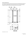
Mechanical Specifications .................................................................................................................... 56 SECTION 19 – ABBREVIATIONS................................................................................................... 57 SECTION 20 – SERVICE AND SUPPORT .................................................................................... 58 Product Warranty, RMA and Contact Information............................................................................... 58 RMA Request........................................................................................................................................ 58 Product Documentation ........................................................................................................................ 58 Technical Support ................................................................................................................................. 58 APPENDIX 1 – WARRANTY STATEMENT .................................................................................... 59 SECTION 1 – PREFACE
Copyright Notice
©2009 CalAmp. All Rights Reserved.
This manual covers the operation of the CalAmp 882-GPRS, 882-EDGE, and 882-HSPA
Cellular Data Modem IP Routers. Specifications described are typical only and are subject to
normal manufacturing and service tolerances.
CalAmp reserves the right to modify the equipment, its specification or this manual without
prior notice, in the interest of improving performance, reliability, or servicing. At the time of
publication all data is correct for the operation of the equipment at the voltage and/or
temperature referred to. Performance data indicates typical values related to the particular
product.
No part of this documentation or information supplied may be divulged to any third party
without the express written consent of CalAmp.
Products offered may contain software which is proprietary to CalAmp. The offer or supply
of these products and services does not include or infer any transfer of ownership.
Modem Use
The 882 GSM Series modems are designed and intended for use in fixed and mobile
applications. “Fixed” assumes the device is physically secured at one location and not easily
moved to another location. Please keep the cellular antenna of the 882 GSM Series modem
at a safe distance from your head and body while the modem is in use (see below).
Important
Maintain a distance of at least 20 cm (8 inches) between the transmitter’s antenna and any
person while in use. This modem is designed for use in applications that observe the 20 cm
separation distance.
Interference Issues
Avoid possible radio frequency (RF) interference by following these guidelines:
•
The use of cellular telephones or devices in aircraft is illegal. Use in aircraft may
endanger operation and disrupt the cellular network. Failure to observe this
restriction may result in suspension or denial of cellular services to the offender,
legal action or both.
•
Do not operate in the vicinity of gasoline or diesel-fuel pumps unless use has been
approved and authorized.
•
Do not operate in locations where medical equipment that the device could interfere
with may be in use.
•
Do not operate in fuel depots, chemical plants, or blasting areas unless use has been
approved and authorized.
•
Use care if operating in the vicinity of protected personal medical devices, i.e.,
hearing aids and pacemakers.
•
Operation in the presence of other electronic equipment may cause interference if
equipment is incorrectly protected. Follow recommendations for installation from
equipment manufacturers.
001-0003-832 Rev3
Page 7 of 59
Mobile Application Safety
•
Do not change parameters or perform other maintenance of the 882 GSM Series
modem while driving.
•
Road safety is crucial. Observe National Regulations for cellular telephones and
devices in vehicles.
•
Avoid potential interference with vehicle electronics by correctly installing the 882
GSM Series modem. CalAmp recommends installation by a professional.
001-0003-832 Rev3
Page 8 of 59
SECTION 2 – PRODUCT OVERVIEW
Module Identification
Label Information
The label contains the CalAmp part number, serial number, FCC ID and the IMEI numbers.
The IMEI number is used by the GSM network to identify valid devices. The IMEI is only used
to identify the device, and has no permanent or semi-permanent relation to the subscriber.
IMEI Dec: The International Mobile Equipment Identity number of the cellular module in
decimal format.
General Description
The 882 GSM Series Cellular Data Modem & IP Router from CalAmp is the ideal solution for a
wide range of cellular data network serial and Ethernet connectivity requirements.
The 882-GPRS modem features GSM GPRS speeds. The 882-EDGE modem features GSM
GPRS and EDGE speeds. The 882-HSPA modem features GSM GPRS, EDGE, HSUPA & HSDPA
speeds. The 882-EDGE and 882-HSPA will automatically be backward compatible to the level
of service available from the carrier. The 882 GSM Series modems all support packet data
services.
Features and Benefits
EDGE and GPRS Dynamic or Static IP – Carrier Dependent
Tri-Band UMTS/HSUPA (850/1900/2100) and Quad-Band GSM/GPRS network support
Data rates up to 7.2 Mbps downlink and 2.0 Mbps uplink for HSPA
Inbound and Outbound Ethernet Routing
Embedded Linux on ARM 9 processor
Internet access and web browsing via Ethernet connector
VPN support
DHCP Server and Inbound port mapping/translation (Port Forwarding)
Modem Domain Names with Dynamic DNS
Inbound IP termination with Static IP
TCP/IP Packet assembler and dis-assembler for serial connected devices
Local or remote configuration using HTML web server
On-board SIM socket (1.8/3V)
Diversity antenna port/auxiliary port for increased receive sensitivity
Firewall configuration for increased network security
USB Host Controller
Catalog Part Number Breakdown
882-GPRS-GEN, 882-EDGE-GEN, & 882-HSPA-XXX
(XXX = Carrier Identifier)
GEN = Generic
INT = International
001-0003-832 Rev3
Page 9 of 59
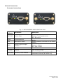
External Connections
Front panel connections
Fig. 2.1 882-GPRS/EDGE & 882-HSPA Front Panel
Panel
Indicator
Connection
SVC TYPE
Service Type
TX/RX
Transmit/Receive
DCD
Data Carrier Detect
RSSI
Receive Signal Strength
Indicator
Serial
RS-232
Solid = Higher speed service
Blinking = Lower speed service
Off = No service
Indication of data transmission or reception
activity
Indicates modem’s connection on the cellular
network
Solid = strong
Blinking = medium
Off = poor or none
Serial to IP conversion use
RF (SMA)
Antenna
Main RF antenna input
AUX (SMA)
Diversity or GPS Antenna
Connector for Diversity or Cellular/GPS
combination antenna (882-HSPA only)
Description
001-0003-832 Rev3
Page 10 of 59
Back panel connections
Fig. 2.2 882-GPRS/EDGE and 882-HSPA Back Panel
Panel
Indicator
ETHERNET
Connection
Description
RJ-45 Ethernet
USB HOST
USB
Interface for Ethernet connection to devices
Interface for external devices (i.e., memory
drives or GPS devices). ODP use only.
One second hold for unit reset. If held for
at least 4 sec, will reconfigure unit to
factory default settings.
RESET
PWR LED
Power indicator
PWR Jack
Molex 43025-0400
Power – bottom pins
I/O – top pins
SIM CARD
SIM Card socket
Interface for power plug (9-28VDC)
Interface for Input and Output control lines
ODP use only.
Interface for carrier provided SIM card to
activate connection with network provider
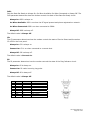
RS-232 Serial Port Integration Parameters
Table 2.1 provides the serial cable design information to integrate the 882 GSM Series modem
into your system.
Table 2.1 Standard RS-232 DE-9 Pin out
Pin
1
2
3
4
5
6
7
8
9
Name
CD
RX
TX
DTR
GND
DSR
RTS
CTS
RI
Direction
«—
«—
—»
—»
«—
—»
«—
«—
Description
Carrier Detect
Receive Data
Transmit Data
Data Terminal Ready
System Ground
Data Set Ready
Request to Send
Clear to Send
Ring Indicator
Note: Direction is DTE relative DCE.
Table 2.2 Default RS-232 Communication Parameters
Bits Per Second
Data Bits
Parity
Stop Bits
Flow Control
115,200
8
None
1
None
001-0003-832 Rev3
Page 11 of 59
Accessories & Options
Accessory/Option
Order Number
Description
401-7500-001
4” Rubber Duck Antenna
L2-ANT0003
3” Mag Mount Antenna
150-7001-001
110 VAC Input Power
150-7500-002
DC Power Cable
L2-CAB0002
DB-9 Serial Cable
L2-CAB0006
Ethernet cable
Primary Antenna
The primary antenna connection on the 882 GSM Series modems are female connectors,
therefore you must purchase an antenna with an SMA male connector. Do not select an SMA
antenna with “reverse polarity” or RP-Male. When using a direct mount or “rubber duck”
antenna, choose the antenna specific to your band requirements. Mounting options and cable
lengths are user’s choice and application specific. The AUX antenna connector is installed
standard on the 882-HSPA modem and can be used for Diversity or True GPS.
001-0003-832 Rev3
Page 12 of 59
The diversity port on the device supports three bands, Cellular (850MHZ), PCS(1900MHZ), and
GPS(1575MHZ). Connect a dual band cellular antenna to this port to implement RX diversity on
the unit and increase receive sensitivity on the cellular network. Connect a GPS antenna, with an
average gain >-5dBi, if using the GPS functionality. If both RX diversity and GPS are required,
install a Cellular/GPS combo antenna.
GSM Communications
Only GSM models have SIM cards. Your wireless service provider will supply the SIM card with
your wireless service contract.
The 882-GPRS supports GPRS data.
The 882-EDGE supports EDGE and GPRS data.
The 882-HSPA supports HSUPA, HSDPA, EDGE and GPRS data.
001-0003-832 Rev3
Page 13 of 59
SECTION 3 – GETTING STARTED
The 882 GSM Series modems can be configured via HTML web pages or AT commands on the serial
port. You will need a GSM Cellular account and a carrier provided SIM card. For TCP/IP please
request a GSM account with Mobile IP and optionally Static IP or Simple IP (SIP). This is carrier
dependent.
The modem is configured with default settings and is ready to be configured via HTML. You may
need to activate the modem with your carrier to start using it. The default settings are programmed
for most operations.
Package Contents
•
•
•
882-GPRS, 882-EDGE, or 882-HSPA cellular data modem
150-7500-002 Power Cable
Information Card
Local PC Ethernet Configuration
The 882 GSM Series modem is configured via the Internet which automatically allows your computer
to obtain the proper IP address. For Windows XP users, select Start -> Control Panel -> Network
Connections. Right click “Local Area Connection” and select “Properties” to open the configuration
dialog box for Local Area Connection. See Figure 3.1.
Figure 3.1: Local PC Network Connections Screen
001-0003-832 Rev3
Page 14 of 59
Find and select “Internet Protocol (TCP/IP)” from the list box and then click the “Properties” button
(Figure 3.1). The TCP/IP configuration window will pop up, refer to Figure 3.2. Under the General
tab, select radio button “Obtain an IP address automatically” and “Obtain DNS server address
automatically” (Figure 3.2). Click the OK button to close TCP/IP configuration window. Click the
Close button to complete the computer preparation for the 882 GSM Series modem.
Figure 3.2: Internet Protocol (TCP/IP) Properties Screen
Connect an antenna to the RF connector on the front panel of the 882-GPRS, 882-EDGE, or 882HSPA modem. Connect the Ethernet cross-over cable into the modem’s Ethernet Port and plug the
other end into the network port of your PC. Connect the Power Adapter to the modem and plug into
a proper AC power socket. The Power LED on the panel should activate. The Service LED (SVC TYPE)
and RSSI LED will light green to indicate the modem has finished starting up and is functioning.
Accessing the Modem’s Homepage
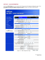
Start your web browser and enter 192.168.1.50 in the address bar. A login screen should appear,
enter the User Name: admin and the Password: password and click OK. Refer to Figure 3.3.
Figure 3.3: 882 GSM Series Browser Connection Login Screen
001-0003-832 Rev3
Page 15 of 59
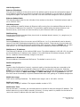
Figure 3.4: 882-HSPA Configuration Home Page (without SIM card)
Web screens are similar for all modems; the top header will display the unit’s model number.
The PPP status on the Home page will show DOWN because the new device is not enabled. The
Service Type will show Check SIM if the SIM is invalid, missing, or if the PIN needs to be entered.
Also, the MDN and IMSI lines show NOT AVALABLE.
001-0003-832 Rev3
Page 16 of 59
Inserting the SIM Card
Power down the unit and insert the SIM card with the gold side up as shown in Figure 3.5. Push the
card completely into the slot until it clicks in place.
Figure 3.5: SIM Insertion
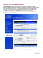
Power up the modem and return to the Home page to confirm the modem recognized the SIM card.
The MDN may show the phone number and the IMSI and carrier information should display. Also,
the PPP connection may not show as up until the SIM card is unlocked. Refer to Figure 3.7.
Select SIM Settings from the left side menu bar (Figures 3.6 & 3.7) to go to the SIM settings page.
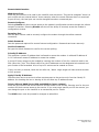
Figure 3.6: SIM Page (with SIM accepted)
The SIM STATUS should show the card is ACCEPTED. The PIN STATUS may show the PIN to be
DISABLED or ACCEPTED. Refer to Section 4 for information on changing the PIN and PIN status.
001-0003-832 Rev3
Page 17 of 59
Figure 3.7: 882-HSPA Home Page (with SIM card, PPP connected)
001-0003-832 Rev3
Page 18 of 59
SECTION 4 – SIM CARD PIN SECURITY SETTINGS
One of the key features of GSM is the Subscriber Identity Module (SIM), commonly known as a SIM
card. The SIM is a detachable smart card containing the user's subscription information. This allows
the user to retain information after switching modems. The SIM has a security feature which, when
enabled, will require the user to enter a valid PIN before the modem will connect to the cellular
network. Selecting SIM Settings from the left menu bar brings up the SIM Settings page. When a
new modem is powered up with an active SIM card, the PIN status may initially be disabled as
shown in Figure 4.1.
Figure 4.1: SIM Settings page, SIM accepted, PIN disabled
001-0003-832 Rev3
Page 19 of 59
Enabling PIN Security
The PIN can be enabled from the SIM page by selecting NO for Disable PIN, entering the current PIN
in the field provided, then clicking the SAVE button. The SIM setting’s page will appear as shown
below in Figure 4.2.
Figure 4.2: PIN Security Enabled
The PIN security feature is now enabled. The PIN STATUS shows that the PIN has been ACCEPTED.
Now, when the modem is power cycled, the proper PIN will need to be entered in order for the
modem to dial out. The PIN is entered from the SIM page as shown in Figure 4.3. The PIN STATUS
displays PIN REQUIRED, Enter PIN 3 attempts left.
001-0003-832 Rev3
Page 20 of 59
Figure 4.3: SIM settings for PIN Required
At this point the user has 3 attempts to enter the correct PIN. If the correct PIN is not entered after
3 attempts, an unlock code or PIN Unblocking Key (PUK) from the service provider will be required
before the SIM card is usable again. Figure 4.4 shows the SIM settings after an incorrect PIN has
been entered.
Figure 4.4: PIN status rejected
001-0003-832 Rev3
Page 21 of 59
Figure 4.5 shows the SIM page requiring the unlock code to be entered. At this point the user has 10
attempts to enter the correct unlock code or the SIM card will be rendered unusable.
Figure 4.5: PIN unlock code required
PIN security options
After PIN security has been enabled, the SIM page will display three options for changing the PIN
functionality, Remember PIN, Disable PIN, or Change PIN. Only one of these options can be
changed and saved at a time.
Remember PIN
Selecting YES will allow the modem to remember the security PIN making it unnecessary to
enter the PIN each time the modem tries to connect to the network. Selecting NO will set the
modem to not remember the current PIN, requiring the user to enter the PIN when requested.
Since only the modem remembers the PIN, using the SIM card in a different modem will require
PIN authorization to dial out.
Disable PIN
Selecting YES will disable the PIN security feature; the current PIN will need to be entered to
allow disabling. A selection of NO indicates that PIN security is enabled.
Change PIN
Selecting YES will allow the user to change the current PIN to a new one. Selecting NO will not
require the user to change the PIN in the New PIN and Confirm PIN fields. When changing PINs,
the user is required to input the current PIN, the new PIN, and the new PIN again in the fields
provided.
After one of the options is changed, click the SAVE button to refresh the page showing the
changes.
001-0003-832 Rev3
Page 22 of 59
SECTION 5 – DIAL SETTINGS
Selecting Cell Connection from the left menu bar, then the Dial Settings tab, brings up the dial
settings page. This provides the interface to configure dialing properties for initiating a data call with
the cellular provider. Refer to Figures 5.1 and 5.2 below.
Figure 5.1: Dial Settings Page 882-GPRS/EDGE
Dial Settings for GPRS/EDGE
Auto Connect:
When set to Enable, will allow the modem to automatically dial the connection when the modem is
powered and will also auto-reconnect if power is cycled. When set to Disable, the modem will not
dial the connection to the cellular provider.
GSM Band:
Selecting “USA” sets the modem to use the 850/1900 MHz GSM band. Selecting “Europe” sets the
modem to use the 900/1800 MHz GSM band.
Carrier APN:
The Access Point Name provided by the cellular provider required to access the network.
Dial Number:
The phone number used to initiate a data connection to the cellular provider via PPP.
User:
Sets the username required by the cellular provider. Leave blank if not required.
Password:
Sets the password required by the cellular provider. Leave blank if not required.
001-0003-832 Rev3
Page 23 of 59
Figure 5.2: Dial Settings Page 882-HSPA
Dial Settings for HSPA
Auto Connect:
When set to Enable, will allow the modem to automatically dial the connection when the modem is
powered and will also auto-reconnect if power is cycled. When set to Disable, the modem will not
dial the connection to the cellular provider.
For 882-GPRS and 882-EDGE units (Figure 5.1):
GSM Band:
Select USA (850/1900MHz) or Europe (900/1800MHZ)
001-0003-832 Rev3
Page 24 of 59
For the 882-HSPAunits (Figure 2.2):
GSM Band selection is as follows:
Band Selection: Configures the unit to operate on only the selected bands if available. We
recommend leaving this on “ALL.”
ALL –
WCDMA 2100 EGSM ALL GSM ALL WCDMA -
All available bands will be accessible, commonly called autoband (default)
Uses the 2100MHz frequency band used by the UMTS/HSDPA networks
Uses the 900/1800 MHz European GSM frequency band
Can use any available GSM band. Europe (900/1800MHz) or USA (850/1900MHz)
Can use any available WCDMA band, 850/900/2100 MHz in UMTS/HSDPA networks
Carrier APN: The Access Point Name provided by the cellular provider required to access the
network.
Dial Number: Field to input the phone number to initiate a data connection to the cellular provider
via PPP. The default dial number is ATD*99***1#.
User: Field to input the username required by the cellular provider. Leave this field blank if a user
name is not required by your cellular provider.
Password: Field to input the password required by the cellular provider. Leave blank if a password
is not required by your cellular provider.
The SAVE button must be pressed for changes to take effect.
001-0003-832 Rev3
Page 25 of 59
SECTION 6 – MAC FILTERING
Selecting LAN Settings from the left menu bar, then the MAC Filtering tab, brings up the MAC
filtering configuration page. MAC filtering allows up to five unique device MAC addresses access to
the network.
Figure 5.1: MAC Filtering Page
MAC Filtering Support
MAC Filtering: Select Enable to allow MAC filtering. Up to five unique MAC addresses can be
allowed to access the network. Selecting Disable will stop the MAC filtering functionality.
Allowed MAC Address: Input MAC address to be allowed access to the network. Up to five
addresses may be input.
Comment: Input name or short description of the device using the allowed MAC address. This field
is limited to 32 characters.
Selecting Clear will remove the MAC address from the list of allowed addresses.
The SAVE button must be pressed for changes to take effect.
001-0003-832 Rev3
Page 26 of 59
SECTION 7 – LAN CONFIGURATION
Selecting LAN Settings from the left menu bar brings up the LAN settings configuration page. From
this page the modem’s IP address, DNS settings, DHCP settings, and Remote Administration
parameters are configured. Refer to Figure 7.1 below.
Figure 7.1: LAN Configuration Page
001-0003-832 Rev3
Page 27 of 59
LAN Configuration
Ethernet IP Address:
This sets the IP address of this device and is the address used to access the configuration pages. If
the IP address changes you will have to re-enter the new IP address in your browser to access the
configuration pages. The default IP is 192.168.1.50 and should be changed for security purposes.
Ethernet Subnet Mask:
This sets the subnet mask for the LAN side of the modem to the device. The default subnet mask is
set to 255.255.255.0.
LAN Masquerade:
When enabled the LandCell directs all Ethernet traffic coming from the tethered Ethernet device to
the Ethernet IP address of the LandCell. This should be enabled when the tethered device is an
Ethernet server, and it does not have the ability to point Ethernet traffic to a gateway.
DNS Resolving
Domain Name System operates like a phone book to translate domain names (i.e., google.com) to
IP addresses (70.212.19.1).
DNS Auto:
Selecting Enable will allow the servers set as DNS Server 1 or 2 to automatically resolve domain
names to the DNS IP addresses assigned by the cellular network. These servers communicate with
name servers by sending DNS queries and heeding DNS responses. Selecting Disable will not allow
DNS Server 1 or 2 to resolve domain names to prevent unauthorized users from web surfing.
DNS Server 1 IP Address:
The Ethernet IP address of the preferred DNS server. The default address is 192.168.1.50, the same
as the LAN Ethernet IP Address of the modem. If the LAN Ethernet ID Address changes, the DNS
Server 1 address will automatically change to the same.
DNS Server 2 IP Address:
Ethernet address of the alternate DNS server. The default is set to 0.0.0.0.
DHCP Configuration
DHCP:
Dynamic Host Configuration Protocol; a protocol used by client devices that are connected to the
LAN port of this device to automatically obtain an IP address assigned by this device. Selecting
Enable will configure this device to assign IP addresses to client devices taken from a pool specified
by the values entered in DHCP start range and DHCP end range. Selecting Disable will turn off
this DHCP server functionality to prevent unauthorized users from getting an IP address assignment.
DHCP start range:
DHCP server starting IP address. The default start range is set to 192.168.1.120-200
DHCP end range:
DHCP server ending IP address. The largest settable number is 253.
DHCP Lease Time:
Sets the duration, in seconds, the connected device is allowed to keep the assigned IP address. The
default lease time is set to 86400 seconds (24 hours). In many cases it is possible for the device to
receive the same IP address after the lease time expires.
001-0003-832 Rev3
Page 28 of 59
Remote Administration
Web Server Port:
Enter the port number to be used by the LandCell local web server. This can be changed if there is a
port conflict with an external device. As an example, when the remote Ethernet device is restricted
to port 80 only, the local port can now be changed to another unreserved port.
Remote Configure:
Selecting Enable will allow remote access to the modem’s configuration screens through the cellular
network connection. Selecting Disable will shut off the ability to remotely access the modem’s
configuration screens.
Incoming Port:
Sets the port number used to remotely configure the modem through the cellular network
connection.
Admin Password:
Sets the password required for remote Internet configuration. Passwords are lower case only.
Confirm Password:
Re-type the Admin Password to confirm the correct spelling.
Friendly IP Address:
This specifies a remote IP address that is allowed to access the modem. A wildcard IP address of
0.0.0.0 allows all remote IP address to access the modem.
A source IP entry range may be created by inserting the number of bits for a network mask in the
fifth (after the /) box. This allows traffic from the IP addresses on the designated sub network and
port number to be forwarded. A list of up to 32 entries can be created at a time.
If only one entry is desired, leave the box after the / blank. Large ranges will take several seconds
to fully process.
Apply Friendly IP Address:
Check the box next to a service to allow remote access to the service only from the friendly IP
address. Un-checking the box or leaving all 0’s will allow any IP address access.
Telnet, SSH and SNMP Ports (SSH and SNMP for future release):
Enter the port number that will be used for remote access to the service. Entering zero for the port
number will block remote access to the service. If you must use a specific port for the remote, you
can change the port on the LandCell to an unreserved port for Telnet.
The SAVE button must be pressed for changes to take effect.
001-0003-832 Rev3
Page 29 of 59
SECTION 8 – DMZ / PORT FORWARDING SETTINGS
Selecting Router from the left menu bar, then the Port Forwarding tab, brings up the port
forwarding configuration page. Port Forwarding is a technique for transmitting and receiving network
traffic through a router that involves re-writing the source and/or destination IP addresses and
usually the TCP/UDP port numbers of IP packets as they pass through. The various routing
configurations will be displayed in the IP mapping table at the bottom of the screen.
DMZ is a host on the internal network that has all ports exposed, except those ports forwarded
otherwise. Refer to Figure 8.1 below.
Figure 8.1: DMZ/Port Forwarding configuration page
001-0003-832 Rev3
Page 30 of 59
DMZ Support
DMZ:
When set to Enable, will allow the modem to use DMZ routes using the address set in the
Destination IP Address. When set to Disable, will shut down the DMZ functionality. This can be
used when one Ethernet device per modem is used. DMZ will forward all ports to the device except
for the ports already specified, see below:
Web server port, remote administration incoming port, SSH port, Telnet port, SNMP port and
incoming serial PAD ports, and any ports listed in the IP mapping table.
The SAVE button must be pressed for changes to take effect.
Friendly IP Address:
This specifies a remote IP address that is allowed to access the modem. A wildcard IP address of
0.0.0.0 allows all remote IP address to access the modem.
A source IP entry range may be created by inserting the number of bits for a network mask in the
fifth (after the /) box. This allows traffic from the IP addresses on the designated sub network and
port number to be forwarded. A list of up to 32 entries can be created at a time.
If only one entry is desired, leave the box after the / blank. Large ranges will take several seconds
to fully process.
Destination IP Address:
The IP address of the tethered device for which all unreserved ports will be forwarded to.
Port Forwarding Support
Port Forwarding Enable:
When set to Enable, will allow the modem to use the Port Forwarding routes described in the IP
mapping table. When set to Disable, will shut down the Port Forwarding functionality.
The SAVE button must be pressed for changes to take effect.
Port Forwarding Configuration
Map Name:
This sets the mapping name for the IP mapping table at the bottom of the screen.
Protocol:
This sets the data protocol as either tcp, udp, or all.
Friendly IP Address:
This specifies a remote IP address that is allowed to access the modem. A wildcard IP address of
0.0.0.0 allows all remote IP address to access the modem.
A source IP entry range may be created by inserting the number of bits for a network mask in the
fifth (after the /) box. This allows traffic from the IP addresses on the designated sub network and
port number to be forwarded. A list of up to 32 entries can be created at a time.
If only one entry is desired, leave the box after the / blank. Large ranges will take several seconds
to fully process.
001-0003-832 Rev3
Page 31 of 59
Inbound Port:
This sets the external port number for incoming requests. To avoid conflict, never reuse any of the
same ports as described in the DMZ section above.
Destination IP Address:
The IP address of the tethered device for which the port specified in the inbound port field will be
forwarded to.
Destination Port:
This sets the LAN port number used when forwarding to the destination IP address.
As an example, if it were required that all incoming addresses using port 81 and 8081 be routed to
IP address 192.168.1.222 on port 80 then the following information would be entered.
First, set the mapping name to 1, set the protocol to all, set the input IP address to 0.0.0.0 and the
incoming port to 81, set the destination IP address to 192.168.1.222 and the destination port to 80,
then click the ADD button. This will set the first entry in the table as Item 1.
To route port 8081 as well, enter a mapping name of 2, set the protocol to all, set the input IP
address to 0.0.0.0 and the incoming port to 8081, then set the destination IP address and port to
the same values as before and click the ADD button. A second entry will be created as item 2,
shown in Figure 9.2 below.
Figure 9.2: Port Forwarding Mapping Table example 1
As a second example, add the requirement to forward information from IP address 66.94.234.13,
port 8083 to IP address 192.168.1.223, port 8083 using the tcp protocol.
Enter a mapping name of 3, set the protocol to tcp, set the input IP address to 66.94.234.13 and the
incoming port to 8083, then set the destination IP address to 192.168.1.223 and the destination
port to 8083, then click the ADD button. A third entry will be created as item 3, shown in Figure 9.3
below.
Figure 9.3: Forwarding Mapping Table example 2
001-0003-832 Rev3
Page 32 of 59
SECTION 9 – DYNAMIC DNS
Selecting Router from the left menu bar, then the Dynamic DNS tab, brings up the dynamic DNS
configuration page. Dynamic DNS is a system which allows the domain name data of a computer
with a varying (dynamic) IP addresses held in a name server to be updated in real time in order to
make it possible to establish connections to that machine without the need to track the actual IP
address themselves at all times. A number of providers offer Dynamic DNS services ("DDNS"), free
or for a charge. For example, a free service provided by NO-IP allows users to setup between one
and five host names on a domain name provided by NO-IP. No-IP is the default DNS service.
NOTE: Dynamic DNS is compatible with the NO-IP service; it is the customer’s responsibility to
verify other Dynamic DNS services are NOIP compatible.
Figure 9.1: Dynamic DNS configuration page
Dynamic DNS:
Selecting Enable will allow the modem to provide the selected service dynamic IP address
information. Selecting Disable will stop any IP information from being sent to the selected service.
Dynamic DNS Address:
The internet address to communicate the Dynamic DNS information to. Default is dynupdate.noip.com.
001-0003-832 Rev3
Page 33 of 59
Port Number:
The port number for the internet address given above.
Default is 8245.
User Account:
The username used when setting up the account. Used to login to the Dynamic DNS service.
User Password:
The password associated with the username account.
Hostname:
The hostname identified to the Dynamic DNS service. For example http:/test.myserver.com. Put in
the browser to connect to the unit remotely instead of the WAN IP address.
Update Interval:
Sets the interval, in minutes (0 to 65,535), the modem will update the Dynamic DNS server of its
carrier assigned IP address. It is recommended to set this interval as long as necessary. Note: Each
update is considered a data call by the cellular provider and could deplete low usage data plan
minutes.
This may not be necessary because every time the IP address is changed, or a reboot occurs, the
device sends out a notification. This can then be usually set at zero.
The SAVE button must be pressed for changes to take effect.
001-0003-832 Rev3
Page 34 of 59
SECTION 10 – ROUTER SETTINGS
Selecting Router from the left menu bar, then the Static Routes tab, brings up the routing
configuration page. Static route tables are created from the Routing screen and appear at the
bottom. Static Routing refers to a manual method used to set up routing between networks.
Figure 10.1: Router Settings Page
Static Routes
Route Name:
Sets the alphanumeric identifier of the static route in the Static Route Table.
Destination IP Address:
Routes matching this destination IP address will be routed to the static route defined in the Local IP
address field.
IP Subnet Mask:
Sets the subnet mask of the destination network.
001-0003-832 Rev3
Page 35 of 59
Gateway IP Address:
Selects ppp (this modem's wireless internet connection), pptp (VPN Client), or the local network IP
address for the gateway to the destination address. As an example, data by default will go through
ppp. But if pptp (VPN Client) is on, routing can go around the VPN by selecting ppp.
Local IP Address:
This is only used if local IP Addr was selected for gateway. Enter the address of the local gateway.
Metric:
Number ranging from 1 to 20. The lower the metric value the higher the route priority.
The ADD button must be pressed to add the configured route to the Static Route Table.
As an example, if a router connected on the Ethernet side of the modem has a gateway IP address
of 192.168.1.2 and is interfaced to network 192.168.2.0 the following would be entered in the Static
Route Table to allow a device to get on the 192.168.2.0 network.
Set the Route Number to 1, name the Route (i.e. Route1), set the destination IP Address to
192.168.2.0, set the IP Subnet Mask to 255.255.255.0, set the Gateway IP Address to 192.168.1.2,
and set the Metric to 1. The entry will be made in the Static Route Table, Figure 11.2 below.
Figure 11.2: Static Route Table example
001-0003-832 Rev3
Page 36 of 59
SECTION 11 – SIMPLE NETWORK MANAGEMENT PROTOCOL (SNMP, FOR FUTURE RELEASE)
Selecting Diagnostics from the left menu bar, then the SNMP tab, brings up the Simple Network
Management Protocol configuration page. SNMP is used in network management systems to monitor
network-attached devices for conditions that warrant administrative attention. SNMP version v1 is
supported.
Figure 11.1: SNMP Settings page
SNMP Configuration
SNMP:
Selecting Enable will allow the SNMP functionality. Selecting Disable will shut off SNMP
functionality.
Read-only Community Name:
The community string used for accessing the read-only Management Information Bases (MIBs).
Read-write Community Name:
The community string used for accessing all Management Information Bases (MIBs) including
writable MIBs.
The SAVE button must be pressed for changes to take effect.
001-0003-832 Rev3
Page 37 of 59
SECTION 12 – POINT-TO-POINT TUNNELING PROTOCOL SETTINGS
Selecting VPN from the left menu bar will display the Point-to-Point Tunneling Protocol (PPTP)
configuration page. PPTP is a method to implement a virtual private network (VPN).
Figure 12.1: PPTP Settings page
001-0003-832 Rev3
Page 38 of 59
PPTP Client Configuration
PPTP Client:
Selecting Enable will allow the PPTP functionality. Selecting Disable will shut off PPTP functionality.
Set Default Route to PPTP:
Selecting Enable will route all IP traffic through the PPTP connection. Selecting Disable will not route
IP traffic through the PPTP connection.
PPTP Server:
The IP address of the VPN server listening for inbound connections.
Username:
The username required by the VPN server.
Password:
The password, associated with the username, required by the VPN server.
The SAVE button must be pressed for changes to take effect.
PPTP Server Configuration
PPTP Server:
Selecting Enable starts our VPN server listening for an inbound connection, and selecting Disable
stops it.
Server Local IP:
The IP address that our modem gives the remote client.
Client IP Range:
The pool of IP addresses assigned to remote clients.
Protocols Allowed:
Selecting a protocol will instruct the VPN server to accept clients who use that authentication
protocol. The server will reject clients using any of the un-selected protocols.
Encryption:
Selecting 'Use MPPE' will enable Microsoft Point-to-Point Encryption for communication between the
server and clients. This option requires the MS-CHAP or MS-CHAPv2 protocol.
The SAVE button must be pressed for changes to take effect.
PPTP Server User Configuration
Full Name:
This name can be used as a more descriptive name for a client. It is not used by the server. No
spaces are allowed in the name.
Username:
The name used by a client to log in to the server.
Password:
The password, with associated username, used by a client to log in to the server.
001-0003-832 Rev3
Page 39 of 59
SECTION 13 – EXTERNAL SERIAL PORT
Selecting Serial from the left menu bar, then the External Serial tab, brings up the serial port and
PAD settings page. The External Serial screen is used to configure the RS-232 Serial Port parameters
and Packet Assembler and Dis-assembler (PAD) functionality. This acts as a serial to IP (and IP to
serial) converter without the need to purchase a separate serial to IP converter. Refer to Figure 13.1
below.
Figure 13.1 Serial Settings page
001-0003-832 Rev3
Page 40 of 59
External Serial Port Configuration
Baud Rate:
Sets the baud rate of the serial port. Settings may range from 300 to 115,200 bits per second. The
default baud rate is 115,200 bps.
Inter Character Timeout:
Sets the interval between packets being sent, no matter the size, from 1 to 65,535 ms.
DTR:
Defines the Data Terminal Ready behavior.
AT&D0: Ignore DTR.
AT&D1: If in the Online Data State, upon an on-to-off transition of DTR, the modem enters
Online Command State and issues an OK result code; the call remains connected. Otherwise,
ignore DTR.
AT&D2: If in the Online Data State or Online Command State upon an on-to-off transition of
DTR, the modem performs an orderly clear-down of the call and returns to the command state.
Automatic answer is disabled while DTR remains off.
AT&D4: The modem auto-dials the default remote station upon an off-to-on transition of DTR
and enters the Online Data State. The modem ends the call and enters the command state upon
an on- to-off transition of DTR.
AT&D5: The modem auto-dials the default remote station upon an on-to-off transition of DTR
and enters the Online Data State. The modem ends the call and enters the command state upon
an off-to-on transition of DTR.
AT&D6: Upon an on-to-off transition of DTR, the modem performs an orderly clear-down of any
session and turns OFF the RF module. Upon an off-to-on transition of DTR, the modem turns ON
the RF module and reestablishes the radio session.
AT&D7: Upon an on-to-off transition of DTR, the modem performs an orderly clear-down of any
session and turns OFF the RF module. Upon an off-to-on transition of DTR, the modem turns ON
the RF module and reestablishes the radio session.
AT&D8: The modem auto-dials the default remote station upon determining DTR is OFF and
enters the Online Data State. The modem ends the call and enters the command state upon
determining DTR is ON.
AT&D9: The modem auto-dials the default remote station upon determining DTR is ON and
enters the Online Data State. The modem ends the call and enters the command state upon
determining DTR is OFF.
Flow Control:
Sets the Flow Control to None or Hardware control.
001-0003-832 Rev3
Page 41 of 59
DSR:
Sets the Data Set Ready to Always On, On When Available, On When Connected or Always Off. The
DSR parameter determines how the modem controls the state of the Data Set Ready circuit.
Always On: DSR is always on.
On When Available: DSR is on when the RF signal present and phone registered on network.
On When Connected: DSR is on when connected to CDMA.
Always Off: DSR is always off.
The default value is Always Off.
CD:
The CD parameter determines how the modem controls the state of Carrier Detect and the amber
CD LED on the front panel.
Always On: CD is always on.
Connect On: CD is on when connected to a remote host.
Always Off: CD is always off.
The default value is Connect On.
RI:
The RI parameter determines how the modem controls the state of the Ring Indicator circuit.
Always On: RI is always on.
Connect On: RI tracks incoming ring pulse.
Always Off: RI is always off.
The default value is Always Off.
Pin
1
2
3
4
5
6
7
8
9
Name
CD
RX
TX
DTR
GND
DSR
RTS
CTS
RI
Direction
«—
«—
—»
—»
«—
—»
«—
«—
Description
Carrier Detect
Receive Data
Transmit Data
Data Terminal Ready
System Ground
Data Set Ready
Request to Send
Clear to Send
Ring Indicator
001-0003-832 Rev3
Page 42 of 59
PAD Settings
Incoming Friendly IP Address:
This specifies a remote IP address that is allowed to access the modem. A wildcard IP address of
0.0.0.0 allows all remote IP address to access the modem.
Incoming Port:
Sets the port number used to forward incoming traffic to the serial port. Inbound traffic with this
port will be forwarded to the serial port in client mode.
Outgoing Port:
Sets the port number used to send outbound traffic from the serial port. These will be packetized
and sent to an external IP address and the port number specified.
PAD Mode:
Select buttons to set the PAD mode of the modem as a Server or Client.
Server mode waits for inbound TCP connections from remote client or UDP data being sent to the
external modem’s IP address. For example, server mode can be used for mobile termination calls.
When in server mode, it is possible for the connected serial device to make an outbound TCP or UDP
connection when an AT Command is issued (remote IP address: port number, e.g.
ATD*166.23.42.10:5000).
Client mode keeps an always-on TCP connection to a remote server or sends all UDP to the IP
address and port number specified. For example, client mode can be used for mobile origination
calls.
Pad Protocol:
Sets the data protocol of the PAD to TCP or UDP data. If you have set PAD Mode as server you
can choose either to support either type of data packets.
TCP Client Keep Alive:
When in client mode and enabled, TCP Keep Alive packets will be sent from the client to the server
periodically in order to detect a broken connection. The modem will automatically try to re-establish
the connection if necessary. Changing this setting will affect the use of TCP Keep Alive on the next
client session. It will not affect an existing session.
TCP Client Keep Alive Time:
Time in seconds between keep alive cycles. A keep alive cycle will consist of one or more keep alive
probes separated by the keep alive interval. If a keep alive time has no response the unit will send
probes.
TCP Client Keep Alive Probes:
Number of keep alive packets that must fail before connection is considered closed.
TCP Client Keep Alive Intvl:
Time in seconds after which a keep alive packet is considered to be failed (if not acknowledged).
Another packet is sent at this time if TCP Client Keep Alive Probes limit has not been reached.
Server Session Closed On:
This is only available if PAD mode is Server. This option selects under which conditions the server
will terminate an established connection. (If the termination of the TCP current connection was not
received properly by the modem then the connection will hang until the modem reboots or one of
the two below methods is invoked.)
001-0003-832 Rev3
Page 43 of 59
New Client: If a different client attempts to connect, it will be successful and the current client
will be forcibly disconnected, without any warning.
Timeout: A new client will be accepted only after a specified timeout. The duration of the
timeout is specified by the Inactivity timeout, or the Hard timeout, or a combination of both.
The default value is New Client.
Server Inactivity Timeout:
Time after which the current connection with Client will be terminated without warning. This time
starts over again each time the Client sends data to the server. This parameter is ignored if the
session closes on New Client. If PAD protocol is tcp, the timeout is specified in minutes. If udp, the
timeout is specified in seconds. The valid range for either is 1-65535. 0 will disable this timer.
If both Inactivity Timeout and Hard Timeout are enabled, (neither is 0), then a client session will be
terminated when either timeout is met. In this case, the value for Hard Timeout must exceed the
value for Inactivity Timeout. If the Inactivity Timeout is met, the client will be terminated. If the
Hard Timeout is exceeded without meeting the Inactivity Timeout, the client will be terminated by
the Hard Timeout.
Server Hard Timeout:
Time after which the current connection with Client will be terminated without warning. This is a
fixed time from the initial connection, no matter how much or how often the Client sends data to
the server. This parameter is ignored if the session closes on New Client. If PAD protocol is tcp, the
timeout is specified in minutes. If udp, the timeout is specified in seconds. The valid range for either
is 1-65535. 0 will disable this timer.
If both Inactivity Timeout and Hard Timeout are enabled, (neither is 0), then a client session will be
terminated when either timeout is met. In this case, the value for Hard Timeout must exceed the
value for Inactivity Timeout. If the Inactivity Timeout is met, the client will be terminated. If the
Hard Timeout is exceeded without meeting the Inactivity Timeout, the client will be terminated by
the Hard Timeout.
PAD Log:
When enabled, as data passes through the PAD, a copy is stored in a log file located on the modem
at /tmp/padlog. The log will stop saving data when full and data is lost at modem reset. This is only
used for debugging purposes and isn’t normally accessible by the user.
The SAVE button must be pressed for changes to take effect.
001-0003-832 Rev3
Page 44 of 59
SECTION 14 – INTERNAL SERIAL PORT
Selecting Serial from the left menu bar, then the Internal Serial tab, brings up the serial port and
PAD settings page. The Internal Serial screen is used to configure the internal RS232 Serial Port
parameters and Packet Assembler and Dis-assembler (PAD) functionality. The PAD feature forwards
requests that come in on a specific port to the internal serial port. Refer to Figure 14.1 below.
Figure 14.1: Internal Serial page
Serial Port Configuration
Baud Rate:
Sets the baud rate of the serial port. Settings may range from 300 to 115,200 bits per second. The
default baud rate is 115,200 bps.
001-0003-832 Rev3
Page 45 of 59
PAD Settings
Remote IP Address:
Sets the IP address of the device using the PAD functionality.
Remote Port:
Sets the port number used by the remote device to accept requests from the LandCell.
Local Port:
Sets the port number used by the LandCell to accept requests from the remote device.
PAD Mode:
Select buttons to set the PAD mode of the LandCell as a Server or Client.
Pad Protocol:
Sets the data protocol of the PAD to tcp or udp data.
TCP Client Keep Alive:
PAD Log:
If enabled, a log of the data passed through the modem is saved at /tmp/intpadlog. The log will stop
saving data when full and data is lost at modem reset.
The SAVE button must be pressed for changes to take effect.
001-0003-832 Rev3
Page 46 of 59
SECTION 15 – SYSTEM MONITOR
Selecting Cell Connection from the left menu bar, then the System Monitor tab, brings up the
system monitor page. The System Monitor page allows the user to set up additional self-monitoring
for the modem to determine when service provider connections may have been terminated. Refer to
Figure 15.1 below.
Figure 15.1: System Monitor page
001-0003-832 Rev3
Page 47 of 59
Periodic Reset Timer
Periodic Reset Timeout:
Sets the Periodic Modem Reset timer to an Interval time, a Scheduled day, or disables it.
Interval Length:
Sets the Periodic Modem Reset time from 15 to 65,535 minutes. The Periodic Reset is disabled when
set to 0. Default is set to 4320 min. (approximately 3 days)
Scheduled Time:
Sets the Periodic Modem Reset to occur at the specified time. Select the days of week desired or 'All'
for everyday. Time is specified as Local Time, based on the location of the modem itself. The
modem's current time is shown on the "home" page.
Periodic Ping Settings
Destination Address:
User may enter an accessible IP address or URL that will respond to a ping command.
Secondary Address:
User may enter an accessible IP address or URL that will respond to a ping command. This address
will be used if the entered number of consecutive ping failures using the first address is reached.
Periodic Ping Timer:
User may enter an interval in increments of 10 seconds. The modem will ping the destination at that
interval. Enter 0 to disable this feature.
Fail Count:
The modem will reset if the number of consecutive ping failures is equal to or greater than this entry
and the secondary address is being used. Otherwise the modem will switch from the first address to
the secondary address for the ping test.
PPP Data Usage Estimates
This section tracks the data received from and transmitted to the cellular network. This is a tool that
may be used to estimate network usage. These totals are tracked by the router. Your carrier
maintains separate statistics from which your billing is determined. One way to use this tool is to
track usage over a fairly short period of typical usage. The total then can be extrapolated to
estimate longer time periods. This router updates these statistics once approximately every 30
seconds. Press the Clear button to reset the totals to 0.
Rx Bytes:
The total number of bytes received by the modem from the cell network. All statistics will be cleared
automatically if this count exceeds 1 billion (1,000,000,000).
Rx Packets:
The total number of TCP and UDP packets received by the modem from the cell network.
Rx Errors:
The number of corrupted TCP and UDP packets received by the modem from the cell network.
Rx Packets Dropped:
The number of TCP and UDP packets received by the modem from the cell network that were not
accepted. This may occur due to memory or throughput problems.
001-0003-832 Rev3
Page 48 of 59
Tx Bytes:
The total number of bytes transmitted by the modem to the cell network. All statistics will be cleared
automatically if this count exceeds 1 billion (1,000,000,000).
Tx Packets:
The total number of TCP and UDP packets transmitted by the modem to the cell network.
Tx Errors:
The number of corrupted TCP and UDP packets received by the modem that were meant to be
transmitted on the cell network.
Tx Packets Dropped:
The number of TCP and UDP packets received by the modem for transmit to the cell network that
was not accepted. This may occur due to memory or throughput problems.
001-0003-832 Rev3
Page 49 of 59
SECTION 16 – FIRMWARE UPDATE
Selecting Firmware Update from the left menu bar brings up the firmware update page. When
newer versions of the modem firmware become available, the user can download the proper file
from the CalAmp web site and manually update the unit by uploading the new firmware. Refer to
16.1 below.
The update file names are:
upgradegprs.tar.gz for the 822-GPRS modem.
upgradeedge.tar.gz for the 822-EDGE modem.
upgradehspa.tar.gz for the 882-HSPA modem.
Figure 16.1: Firmware Update page
Current Firmware Information
Version:
Displays the modem firmware version currently loaded in the unit.
Kernel Date:
Displays the date of the operating system kernel the unit is running.
001-0003-832 Rev3
Page 50 of 59
Upload New Firmware
File:
Field to input the downloaded update file to the modem. The Browse button can be used to locate
the file in a specific folder. The update can be done remotely if Remote Administration is enabled.
Progress:
Displays the update progress after the Save button has been pressed.
Configuration File
File:
Field to input the uploaded configuration file to the modem. The Browse button can be used to
locate the file in a specific folder. The file to be uploaded must be named config.xml. If multiple
files need to be maintained, it is recommended that separate directories be used. The update can be
done remotely if Remote Administration is enabled.
Select the Upload button to upload the new configuration file to the LandCell unit.
Save:
Returns a link to the configuration file on the unit. Right-click the link and select "Save Target As..."
to save the file to the external location. The link page refreshes after 15 seconds. It is recommended
to use the specified filename to save the file. If multiple files need to be maintained, it is
recommended to use directory paths to separate the files.
001-0003-832 Rev3
Page 51 of 59
SECTION 17 – LOGGING
Selecting Diagnostics from the left menu bar, then the Logging tab, brings up the logging page.
The Logging page provides a way to capture the current status log of the modem. Such a log may be
useful to CalAmp Technical Services personnel to help resolve operational problems. Refer to Figure
17.1 below.
Figure 17.1: Logging page
Current Firmware Information
Version:
Displays the modem firmware version loaded in the unit.
Kernel Date:
Displays the date of the operating system kernel the unit is running.
001-0003-832 Rev3
Page 52 of 59
Log File Actions
Store in Modem:
Selecting Store in Modem and pressing Go creates a current status log. Completing a Store in
Modem will overwrite existing status logs.
Display:
Selecting Display and pressing Go will display a previously stored log directly to the web browser.
You can use your mouse to select the text, copy it, and paste it into a text editor to save the log on
your computer.
TFTP to Server:
Selecting TFTP to Server and pressing Go will initiate a transfer of a previously saved log file to a
specified IP address using the TFTP protocol. In order for the transfer to be successful, a reachable
IP address must be entered under TFTP Server IP and the computer at that IP address must be
running a TFTP Server program. Many free TFTP Servers are available for download over the
internet. Note that TFTP is different than FTP.
TFTP Server IP:
When selecting TFTP to Server and pressing Go a valid and reachable IP address must be entered
here in order to complete the transfer of the saved log file using the TFTP protocol. In order for the
transfer to be successful, a reachable IP address must be entered under TFTP Server IP and the
computer at that IP address must be running a TFTP Server program. Many free TFTP Servers are
available for download over the internet. Note that TFTP is different than FTP.
USB Flash Drive
Unmount:
Unmount a flash drive plugged into the USB port. This drive is mounted at /mnt/flash. For ODP use
only.
001-0003-832 Rev3
Page 53 of 59
SECTION 18 – SPECIFICATIONS
Product specifications are subject to change without notice.
General Specifications
Interface Connectors:
RS-232 DE-9S Connector (DCE)
10/100 Base-T Full Duplex
USB Host Controller
Power Connector I/O
Power Connector:
Molex Micro-Fit, 4 pin, PN:43045-0400
LED Indicators:
SVC-TYPE, TX/RX, DCD, RSSI
Antenna Interface:
SMA female
Size:
5.60 x 3.11 x 1.71 in.
Weight:
9.0 oz.
Power Input:
9.0
9.0
9.0
9.0
Input Pin:
Drive with open collector or open drain, internal 18k ohm pull up
to 3.3VDC.
Output Pin:
Open collector with series 0 ohm resistor as fuse.
Maximum TX Power:
GSM: +33 dBm min. / +30 dBm min (1900MHz)
–
–
–
–
28VDC
28VDC
28VDC
28VDC
1.8
4.7
7.5
7.0
W;
W;
W;
W;
150
390
625
590
mA
mA
mA
mA
@
@
@
@
12
12
12
12
VDC
VDC
VDC
VDC
(average idle)
(peak active 882-GPRS)
(peak active 882-EDGE)
(peak active 882-HSPA)
Rx Sensitivity:
GSM: > -108 dBm typical, -102 dBm min.
Frequencies:
Cellular:
PCS:
Temperature:
Operating: -30°C to +75°C (-22° to 167°F) 100% Duty Cycle
Storage: -40°C to +85°C (-40° to 185°F)
Note: RF performance of the cell module may be limited above 60°C.
Emissions:
FCC Part 15B
TX: 824-849 MHz
TX: 1850-1910 MHz
Rx: 869-894 MHz
Rx: 1930-1990 MHz
Transport Protocols:
UDP/TCP
Command Protocol:
Web interface, Command line v.250 AT, & proprietary
Certifications:
882-GPRS
882-EDGE
882-HSPA
PTCRB Approved, Various Carrier Approvals
FCC ID: QIP-TC65
Industry Canada ID: IC: 267W-TC65
CE Approved
RoHS Compliant
PTCRB Approved, Various Carrier Approvals
FCC ID: QIP-MC75
Industry Canada ID: IC: 267W-MC75
CE Approved
RoHS Compliant
PTCRB Approved, Various Carrier Approvals
FCC ID: N7N-MC8781
Industry Canada ID: 2417C-MC8781
CE Approved
RoHS Compliant
NOTE: Power consumption while transmitting is dependent on the TX power level of the cellular module. The TX
power level of the module is controlled by the cellular base station.
001-0003-832 Rev3
Page 54 of 59
DECLARATION OF CONFORMITY FOR CE MARKING
Company contact details
Calamp Wireless Datacom, 299 Johnson Avenue, Suite 110,
Waseca, MN 56093-0833, USA
Phone: (507) 833-8819
Fax: (507) 833-6748
Calamp Wireless Datacom declares that their:
Cellular Data Modems
Model numbers:
819-GPRS-GEN, 822-GPRS-GEN, 822-EDGE-GEN, 882-HSDP-GEN.
are classified within the following EU Directives:
EU Directive 2006/95/EC Low Voltage
EU Directive 89/336/EEC & 2004/108/EC EMC
EU Directive 1999/5/EC R&TTE
and further conform with the following EU Harmonized
Standards:
EN 60950-1:2006
EN 55024:1998+A2:2003
EN 55022:2006+A1:2007
Position of signatory: Director of Engineering
Name of Signatory: Chris Ludewig
Signed:
Dated: 5/8/08
Mechanical Specifications
The following section describes in detail the exterior dimensions of the 882 GSM Series modems and
how to utilize the mounting flanges to secure the modem to any surface, which can be drilled for
such a purpose. The drawings may be used as layout reference, but it is advised that a physical
comparison be made to the modem before proceeding with the mounting process.
All dimensions in inches.
001-0003-832 Rev3
Page 56 of 59
SECTION 19 – ABBREVIATIONS
Abbreviation
Description
APN
Access Point Name
CSD
Circuit Switched Data
CTS
Clear to Send
DCD
Data Carrier Detect
DCE
Data Communication Equipment
DTE
Data Terminal Equipment
IMEI
International Mobile Equipment Identity
EDGE
Enhanced Data rates for Global Evolution
GPRS
General Packet Radio Service
GPS
Global Positioning System
GSM
Global System for Mobile communication
HSDPA
High-Speed Downlink Packet Access
LED
Light Emitting Diode
ME
Mobile Equipment
MS
Mobile Station
OTA
Over the Air
PDP
Packet Data Protocol
PPP
Point-to-Point Protocol
PPTP
Point-to-Point Tunneling Protocol
PRL
Preferred Roaming List
RSSI
Receive Signal Strength Indication
Rx
Receive
Tx
Transmit
001-0003-832 Rev3
Page 57 of 59
SECTION 20 – SERVICE AND SUPPORT
Product Warranty, RMA and Contact Information
CalAmp guarantees that every 882 GSM Series Cellular Modem will be free from physical
defects in material and workmanship for one (1) year from the date of purchase when used
within the limits set forth in the Specifications section of this manual.
The manufacturer's warranty statement is available in Appendix 1. If the product proves
defective during the warranty period, contact CalAmp Customer Service to obtain a Return
Material Authorization (RMA).
RMA Request
Contact Customer Service:
CalAmp
299 Johnson Avenue, Suite 110
Waseca, MN 56093
Tel: 507-833-8819 ext. 6707
Fax: 507-833-6748
BE SURE TO HAVE THE EQUIPMENT MODEL AND SERIAL NUMBER, AND BILLING AND
SHIPPING ADDRESSES ON HAND WHEN CALLING.
When returning a product, mark the RMA clearly on the outside of the package. Include a
complete description of the problem and the name and telephone number of a contact
person. RETURN REQUESTS WILL NOT BE PROCESSED WITHOUT THIS INFORMATION.
For units in warranty, customers are responsible for shipping charges to CalAmp. For units
returned out of warranty, customers are responsible for all shipping charges. Return shipping
instructions are the responsibility of the customer.
Product Documentation
CalAmp reserves the right to update its products, software, or documentation without
obligation to notify any individual or entity. Product updates may result in differences
between the information provided in this manual and the product shipped. For the most
current product documentation, visit www.calamp.com for datasheets, programming software
and user manuals.
Technical Support
M-F 7:30 AM to 4:30 PM CDT
CalAmp
299 Johnson Avenue, Suite 110
Waseca, MN 56093
Tel: 507-833-8819
E-mail: [email protected]
001-0003-832 Rev3
Page 58 of 59
APPENDIX 1 – WARRANTY STATEMENT
CalAmp warrants to the original purchaser for use ("Buyer") that data telemetry products
manufactured by DRL ("Products") are free from defects in material and workmanship and will
conform to DRL’s published technical specifications for a period of, except as noted below, one (1)
year from the date of shipment to Buyer. DRL makes no warranty with respect to any equipment not
manufactured by DRL, and any such equipment shall carry the original equipment manufacturer's
warranty only. DRL further makes no warranty as to and specifically disclaims liability for,
availability, range, coverage, grade of service or operation of the repeater system provided by the
carrier or repeater operator. Any return shipping charges for third party equipment to their
respective repair facilities are chargeable and will be passed on to the Buyer.
If any Product fails to meet the warranty set forth above during the applicable warranty period and
is returned to a location designated by DRL, DRL at its option, shall either repair or replace such
defective Product, directly or through an authorized service agent, within thirty (30) days of receipt
of same. No Products may be returned without prior authorization from DRL. Any repaired or
replaced Products shall be warranted for the remainder of the original warranty period. Buyer shall
pay all shipping charges, handling charges, fees and duties for returning defective Products to DRL
or DRL’s authorized service agent. DRL will pay the return shipping charges if the Product is repaired
or replaced under warranty, exclusive of fees and duties. Repair or replacement of defective
Products as set forth in this paragraph fulfills any and all warranty obligations on the part of DRL.
This warranty is void and DRL shall not be obligated to replace or repair any Products if (i) the
Product has been used in other than its normal and customary manner; (ii) the Product has been
subject to misuse, accident, neglect or damage or has been used other than with DRL approved
accessories and equipment; (iii) unauthorized alteration or repairs have been made or unapproved
parts have been used in or with the Product; or (iv) Buyer failed to notify DRL or DRL’s authorized
service agent of the defect during the applicable warranty period. DRL is the final arbiter of such
claims.
THE AFORESAID WARRANTIES ARE IN LIEU OF ALL OTHER WARRANTIES, EXPRESSED AND
IMPLIED, INCLUDING BUT NOT LIMITED TO, ANY IMPLIED WARRANTY OF MERCHANTABILITY OR
FITNESS FOR A PARTICULAR PURPOSE. DRL AND BUYER AGREE THAT BUYER'S EXCLUSIVE REMEDY
FOR ANY BREACH OF ANY OF SAID WARRANTIES IT AS SET FORTH ABOVE. BUYER AGREES THAT IN
NO EVENT SHALL DRL BE LIABLE FOR INCIDENTAL, CONSEQUENTIAL, SPECIAL, INDIRECT OR
EXEMPLARY DAMAGES WHETHER ON THE BASIS OF NEGLIGENCE, STRICT LIABILITY OR
OTHERWISE. The purpose of the exclusive remedies set forth above shall be to provide Buyer with
repair or replacement of non-complying Products in the manner provided above. These exclusive
remedies shall not be deemed to have failed of their essential purpose so long as DRL is willing and
able to repair or replace non-complying Products in the manner set forth above.
This warranty applies to all Products sold worldwide. Some states do not allow limitations on implied
warranties so the above limitations may not be applicable. You may also have other rights, which
vary from state to state.
EXCEPTIONS
ONE YEAR:
Labor to replace defective parts in repeaters or base stations
THIRTY DAY:
Tuning and adjustment of telemetry radios
NO WARRANTY: Fuses, lamps and other expendable parts
Effective 1/2008
001-0003-832 Rev3
Page 59 of 59