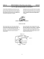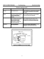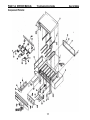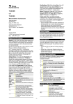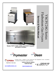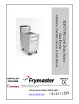
1
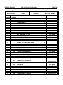
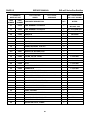
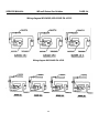
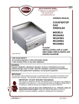
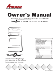
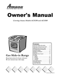
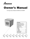
SERVICE MANUAL
WG SERIES GAS GRIDDLES
WELLS MANUFACTURING COMPANY
Revision 04/15/93
Replaces Preliminary
Manual Dated 12/17/91
P.O. Box 280 VERDI, NV. 89439
PHONE: (702)345-0444
FAX: (702) 345-0569
Part # 62453
10/10/95
Data sheets and text of this manual are representative of current production
models as of 12/17/91. Specifications, Model Number designations and data are
subject to change at any time without notice!
CAUTION: NEVER SUBMERGE ELECTRICAL EQUIPMENT
IN WATER. AVOID CONTAMINATING ELECTRICAL COM
PONENTS WITH MOISTURE WHEN CLEANING CABINET
SURFACES.
When service is required to correct electrical or temperature complaints, always
refer service to a Factory Authorized Wells Service Agency or Authorized Sub
Servicer. For location of your nearest Servicer, refer to publication 37000 for a
complete listing of Factory Authorized Service Agency.
CAUTION:
When servicing or cleaning the equipment in
this manual, always remove live power (if used
in this appliance) for safety. Use proper cautions when power must be restored while making voltage or current measurements to avoid
the possibility of electrical shock!
NOTE: The statement above is a general warning and may not
apply to the appliance covered in this manual or gas products
that do not have power connected to the appliance.
THIS MANUAL HAS BEEN FORMATED FOR USE BY WELLS
FACTORY AUTHORIZED SERVICE AGENCY TECHNICIANS
01/10/92 Rev.__
SERVICE MANUAL
WG-xxG Series Gas Griddles
TABLE OF CONTENTS
INTRODUCTION
1-1
INSTALLATION REQUIREMENTS
1-1
INSTALLATION CLEARANCES
1-1
VENTING REQUIREMENTS
1-1
GAS PIPING REQUIREMENTS:
PRESSURE REGULATOR
1-1
GAS PIPING PRESSURE TESTING
1-2
GAS SUPPLY FLOW/VOLUME REQUIREMENT
1-2
LEVELING GRIDDLE
1-2
WARRANTY STATUS
1-2
WARRANTY NOTICE
1-3
OPERATION:
PURPOSE
2-1
OPERATION
2-1
CLEANING
2-1
SEASONING
2-1
DAILY MAINTENANCE AND CARE
2-1
INSTALLATION:
TESTING GAS PRESSURE
3-1
PURGING RAW GAS
3-1
LIGHTING PILOTS
3-1
PILOT FLAME ADJUSTMENT
3-1
MAIN BURNER AIR/FUEL MIXTURE
3-1
SETTING ZONE THERMOSTATS
3-2
REVIEW OPERATION OF GRIDDLE
3-2
i
SERVICE MANUAL
WG-xxG Series Gas Griddles
TABLE OF CONTENTS
SERVICE:
CONTROL CALIBRATION REQUIREMENT
4-1
IMPORTANT CALIBRATION CAUTION
4-1
THERMOSTAT CAUBRATION TOOL
4-1
PLACEMENT OF TEST PYROMETER OR THERMOMETER
4-1
INITIAL HEATING CYCLE
4-1
CAUBRATION
4-1
REPLACEMENT PARTS CAUTIONS
4-2
CONTROL THERMOSTATS
4-2
REPLACING GAS VALVES
4-2
REPLACING PILOTS AND THERMOPILES
4-3
REPLACING PILOT ORIFICES
4-3
REPLACING BURNER ORIFICES
4-3
REPLACING REGULATOR ASSEMBLY
4-3
MAIN BURNER SERVICE
4-3
PILOT FLAME AND MAIN BURNER ADJUSTMENTS
4-4
THERMOPILE OUTPUT VOLTAGE
4-4
THERMOSTAT CONTACT TESTING
4-5
THERMOSTAT REPLACEMENT PART
4-5
TROUBLESHOOTING GUIDE
5-1
COMPONENT PICTORIAL
5-4
COMPONENT ITEM CHART
6-1
WIRING DIAGRAM WG-2424G
6-3
WIRING DIAGRAM WG-2436G, WG-3036G, WG-3048G
6-4
iii
SERVICE MANUAL
WG-xxG Series Gas Griddles Introduction
PAGE 1-1
INTRODUCTION
Wells Heavy Duty, High Performance WG Series Gas
Griddles are designed to cook a full range of food
items, from eggs to steaks. Grills effectively at both
low and high temperatures for maximum versatility.
Fully controllable from 200" F. to 450' F. These Gas
Griddles are available in Natural Gas and Propane
versions.
WG2436G, a 36" x 25%" Cooking Surface, 75,000
BTU per hour rated. WG3036G. a 36" x 30" Cooking
Surface, 75,000 BTU per hour rated. WG3048G. a
48" x 30" Cooking Surface, 100,000 BTU per hour
rated.
These new Gas Griddles utilize a snap action control.
thermostat. No flame modulation is employed and no
bypass flame adjustments are required like former
models of Wells Gas Griddles used.
Chrome Plated and Grooved surface tops are options.
Four basic countertop griddles are available as,
WG2424G, a 24" x 25%'* Cooking Surface, 50,000
BTU per hour rated.
INSTALLATION REQUIREMENTS
WG Series Griddles are design certified for
installation only on a non-combustible counter
top. Formica or other non-metallic laminate over
a combustible material is not considered noncombustible.
Caution: Do not operate griddle without legs
installed. Four inch high sanitary legs are
provided with each Griddle and must be installed
prior to operating the appKance.
INSTALLATION CLEARANCES
A minimum of 3" between the rear and side panels of
the griddle and non-combustible walls adjacent to the
griddle. A minimum of 3 feet of open space in front of
the Griddle must be maintained for space to service
the Griddle.
The area surrounding the Griddle must be kept free
and clear of loose combustible materials. A partial list
would include: Rags, Paper items. Mops or electrical
cords.
VENTILATING REQUIREMENTS
N.F.P.A. # 96. The venting of the Griddle must
not in any way be obstructed or obstruct the flow
of combustion air for proper combustion.
Venting for the Griddle must comply with the
applicable portion of the Standard for the Installation
of Equipment for the Removal of Smoke and Grease
Laden Vapors from Commercial Cooking Equipment,
GAS PIPING REQUIREMENTS
PRESSURE REGULATOR
The Regulator must be installed with the outlet
connection connected to the inlet pipe of the
Griddle. Failure to install or reversing the
connections of the Regulator will void the
warranty and may result in a hazardous condition
and or damage the gas valves.
Each Griddle is shipped with a pressure regulator
matching the fuel type that the griddle and its gas
valves, pilots, and burner orifices are designed to
operate on.
GAS PIPING REQUIREMENTS Continued on next page.
1
PAGE 1-2
SERVICE MANUAL WG-xxG Series Gas Griddles
Introduction
GAS PIPING REQUIREMENTS Cont
Supply piping should be a minimum of % inch
black iron pipe with a sediment trap (drip leg)
consisting of a pipe tee, 4" nipple with cap to
prevent dirt from entering the control valves
(Consult local codes and ordinances for
guidance for this requirement, or in the
absence of local codes, use the National Gas
Code ANSI Z223.1 and NFPA No. 54).
Do not use Teflon Tape or Teflon pipe Compound
on the inlet connections, use a good quality pipe
thread compound. Apply pipe dope sparingly to
the male threads only.
Be sure all gas piping is clean and free of
obstructions, dirt, and piping compounds. A
manual shut-off valve between the % inch feed
pipe and the system manifold should be installed
for safety when servicing the griddle.
Pipe thread compounds should be of a type that
is resistant to the action of LP (Liquid Petroleum
Gases).
GAS PIPING PRESSURE TESTING
Make sure the supply piping system has been
pressure tested before the regulator and griddle
is connected. If the system must be re-tested, be
sure the regulator is isolated by a manual shut-off
valve to prevent damage to the regulator and
griddle gas valves.
The main system piping must be capable of
supplying Griddle with sufficient volume/flow of
fuel for maximum input (Operational)
requirements.
NOTE:
The maximum inlet pressure from the
supply piping should not exceed % P.S.I.
(14" W.C.). Pressures above this limit will
damage the regulator and gas valves hi
the unit.
Always check piping joints for leaks with a soap
and water or other approved leak detection
solution after any pipe connections are disturbed
or changed.
GAS SUPPLY FLOW/VOLUME REQUIREMENT
When testing for adequate gas pressure, be sure all
other gas appliances that utilize the same source
piping are in operation with burners "ON" for an
accurate operational condition.
If other appliances are not consuming gas when
testing for pressure, the test may be inaccurate if flow
volume is marginal in the system supply piping.
LEVELING GRIDDLE
Re-check the leveling after piping connections
are completed to avoid improper cooking on a
slanted surface.
Make sure the griddle is level before connecting to the
gas supply piping.
WARRANTY STATUS
WELLS MANUFACTURING COMPANY STANDARD LIMITED
WARRANTY APPLIES TO ALL WG SERIES GAS GRIDDLES HAVE
COVERAGE FOR PARTS AND LABOR FOR ONE -YEAR FROM THE
DATE OF INITIAL INSTALLATION OR FIRST TIME OPERATION OR
START-UP. OR, 18 MONTHS FROM THE DATE OF MANUFACTURE.
2
Service Manual
WG-xxG Series Griddles Introduction
PAGE 1-3
WARRANTY SERVICE PROVIDED AT THE CUSTOMERS JOB SITE IS LIMITED TO A
60 MILE RADIUS FROM THE CLOSEST WELLS AUTHORIZED SERVICE COMPANY
LOCATION AND MUST BE PERFORMED DURING SERVICE
WORKING HOURS. ADDITIONAL TRAVEL TIME, MILEAGE, AND LABOR CHARGES
ARE THE END USERS RESPONSIBILITY. CALIBRATION 60 DAYS
FROM THE DATE OF INSTALLATION. SEE THE WARRANTY STATEMENT
PUBLISHED IN ITEM NUMBER 37001 (WARRANTY STATEMENT AND SERVICE
AGENCY LISTING) FOR ADDITIONAL INFORMATION ON WARRANTY LIMITATIONS
NOTICE:
Manufacturer's warranty is in effect only when the
griddle is installed by qualified personnel and
operated in accordance with the instructions in
the owners guide and local ordinances or, in the
absence
of local codes, the National Fuel Gas Code,
A.N.S.I. Z223.1-1984 or the latest A.N.S.I. Z223.1
edition. Wells Mfg. Co. is not liable for any
damage resulting from failure to comply with this
notice.
3
SERVICE MANUAL
GW-xxG Series Gas Griddles Operation
PAGE 2-1
OPERATION
PURPOSE
Wells WG Series Griddles provide a heavy duty
gas fired platen for grilling food products.
To set the desired cooking temperatures the front
panel covering the control thermostats must be
lowered to expose the control knobs.
Variations in cooking surfaces include grooved
segments in multiples of 6 inches to provide a
charbroiled appearance to the meat when
cooking. A mirror like Chrome Plated surface is
also available for a reduced sticking cooking
surface.
A pair of magnetic catches and hinges secure the
front panel to the body of the griddle: Operations
including lighting the pilots, setting temperatures
can be accessed though this panel.
CLEANING
Use only PDA approved cleaners and water to
remove food particles after scraping away the
larger waste from the cooking surface. Never use
steel wool to clean the griddle.
Detailed instructions for cleaning the griddle can
be found in the owners guide furnished with each
griddle. After cleaning the cooking surface the
griddle must be re-seasoned.
SEASONING
IMPORTANT: Unless the food product
contains fat, the griddle surface must be
seasoned before each cooking operation.
After each cleaning session, the cooking surface
must be seasoned by preheating the surface to
400° F. Spread a light film of unsalted cooking oil
or fat over the entire cooking surface. Allow the
oil/fat to stand for two (2) minutes and then wipe
clean, repeat the process, then thoroughly wipe
off the excess oil/fat.
Clean the surface with a spatula to remove
excess fat and food. Wipe all the other surfaces
clean with a clean damp cloth and dry.
DAILY MAINTENANCE AND CARE
Scrape crumbs and excess fat into the grease
trough and down the grease chute into the
grease drawer. Remove Grease Drawer (See
Warning at right) by slowly pulling straight out
from the griddle front panel.
WARNING: Use caution when removing the
grease drawer from the griddle to avoid splashing
or spilling hot oil/fat over the sides or end of the
drawer assembly.
REFER TO THE CLEANING/MAINTENANCE SECTION OF THE OWNERS
GUIDE FOR ADDITIONAL INFORMATION ON MAINTAINING THE GRIDDLE
5
SERVICE MANUAL
WG-xxG Series Gas Griddles Installation
PAGE 3-1
TESTING GAS PRESSURE
Ports for measuring outlet gas pressure are
located on the end of each valve below the red
terminal block, a port (# 40 Plug) is also available
on the manifold.
The regulator Has an adjustment screw under the
cap at the raised center of the body of the
regulator. Outlet pressure is factory set at the
regulator manufacturer for 5 inches (W.C.) for
Natural Gas and 10 inches (W.C.) for Propane
Gas.
To connect a water column gauge, remove the
grease drawer to gain access to the left side
valve, remove the alien head screw plug sealing
the test port, install an adapter fitting in the test
port and connect the hose of the gauge.
If adjustment is required, remove the cover screw
on the regulator, adjust the inner screw counterclockwise to increase the pressure and clockwise
to decrease.
PURGING RAW GAS
When using LP. Gas, remember that it is
heavier than air. Sniff at floor level for
presence of LP. Gas. If present do not attempt
to start or light plots.
Caution must be taken to ensure that no raw gas
is present in the surrounding area before
attempting to place the griddle into operation.
LIGHTING PILOTS
Each burner assembly has a pilot assembly that must
be lighted before the matching main burner can be
operated. To light the pilot, (You need a LONG Match)
set thermostat control knob(s) to the "OFF" position.
After the pilot flame has been established the
match can be withdrawn, continue to press in the
knob for approximately 30 seconds, slowly
release the knob.
Press in and rotate the plastic control knob on the gas
valve to 'PILOT' position, continue to press in on knob,
feed a lighted long match through the rectangular
viewing cut-out adjacent to the pilot assembly.
The pilot flame should be set to cover a % to Yi
inch tall section of the thermopile to ensure that
the thermopile will energize the pilot valve and
maintain the pilot flame.
If the pilot flame is set too high or low, see the
“pilot flame adjustment” below.
PILOT FLAME ADJUSTMENT
The adjustment screw for setting pilot flame level is
located under the slotted metal cap just to the left of
the pointer for the control knob on the gas valve.
3/8" to 1/2"
flame is desired
To increase the flame level, turn the adjustment screw
inside the valve counter-clockwise to decrease the
flame turn it clockwise.
Replace the cover after the correct pilot flame level
has been set.
MAIN BURNER AIR/FUEL MIXTURE
loosened to rotate the mixing collar to add or
subtract the amount of combustion air mixed with
the incoming gas as it enters the main burner to
produce a steady blue flame.
Each main burner has an adjustment collar at the inlet
end of the burner. This collar is locked from turning by
a 5/16" hex head screw that must be
7
PAGE 3-2 SERVICE MANUAL
WG-xxG Series Gas
Griddle Installation
SETTING ZONE THERMOSTATS
Each heated zone of the cooking surface has a snap
action thermostat to control the gas valve for that
section. Access to set each control knob is by lowering
the front panel.
After the pilots have been lighted and proven
established, turn rotate the knob to the desired (200*
to 450° F.) temperature.
After the surface has heated and the thermostats have
cycled several times, the surface temperature should
be within ± 25°F. of the dial setting. Variations of less
than ± 25° are normal and can be compensated for by
simply adjusting the knob to get the desired
temperature.
Each thermostat is fitted with a control knob dial
scaled, "OFF"-200" to 450° F.
Each thermostat mounting bracket has a "V" notch at
the top as a pointer index for setting the control dial
knob.
REVIEW OPERATION OF GRIDDLE
After all operational tests have been completed it is
advisable to show the end user each control and their
functions in operation of the griddle.
A review of the operating instructions with the end user
will reduce unnecessary calls for assistance at a later
date.
8
SERVICE MANUAL
WG-xxG Series Gas Griddles SERVICE
PAGE 4-1
CONTROL CALIBRATION REQUIREMENT WG-2424G to WG-3048G SERIES GRIDDLES
Calibration should not be attempted if the dial
can be adjusted to compensate for the
temperature variation, or, if the actual griddle
surface temperature varies from the dial
setting by more than 125° F.
Variations of less than ± 25° F. should be
compensated for by adjusting the control dial
up or down to the desired surface
temperature.
IMPORTANT CALIBRATION CAUTION
WARNING: CALIBRATION HAS A UNITED RANGE,
A TURN OF 1/8 OF REVOLUTION ON THE SCREW WILL
PERMANENT DAMAGE MAY OCCUR IF THE SCREW IS
ROTATED MORE THAN ONE FULL TURN.
CAUSE A 10 - 15' F. OF CHANGE.
THERMOSTAT CALIBRATION TOOL
Calibration of the control thermostat may be
accomplished by adjusting the small screw in
center of the metal control shaft.
The small flat blade screwdriver required to fit
the screw must be a maximum of no more
than 3/32 of an inch wide.
PLACEMENT OF TEST PYROMETER OR THERMOMETER
Place the sensor probe of a (known accurate)
pyrometer in the area directly above the
sensing bulb of the thermostat to be
calibrated.
This will place the probe on the cooking
surface and centered front to back and side
to side in the heated zone of the thermostat
being calibrated.
INITIAL HEATING CYCLE
Be sure to allow several on/off cycles before
adjusting to avoid overshoot on the initial
heating cycle.
Failure to observe this precaution will result in an
inaccurate adjustment while calibrating the
thermostat.
CALIBRATION
To increase the temperature, turn the
adjusting screw counter clockwise, to
decrease the temperature, turn the screw
clockwise. Apply a small amount of sealant
(build a bridge of sealant) to the head of the
calibration screw and inside of the control
shaft after completing calibration.
Failure to lock the adjusting screw from
changing with sealant can result in a drifting
problem wit the thermostat.
A NOTE HERE; if more than 1 full turn is
required, replace the thermostat Use only
genuine O.E.M. parts.
9
PAGE 4-2 SERVICE MANUAL
WG-xxG Series Gas Griddles_
________SERVICE
REPLACEMENT PARTS CAUTIONS
When replacing the control thermostats,
thermopiles, pilots, and control valves, be
sum them is no possibility of hot electrical
terminals touching the capillary tubes, case,
or other conductive parts.
Be sum to dean and re-dope all pipe thread
connections. Apply dope only to the mate
threads when assembling pipe fittings. Always
do a thorough teak check after working on
threaded fittings.
CONTROL THERMOSTATS
Changing thermostats can be accomplished
through the front by dropping the control
panel (# 54), remove the knob (# 20) by pulling
straight off the shaft. remove the wiring from
the control thermostat (# 18), remove the 2
screws that mount the (# 19) bracket to the
main lower frame member. Remove both
mounting screws of the thermostat from the
bracket, re-mount bracket (# 19) to the new
thermostat.
Early production units have 1/4 push-on
terminals on the thermostat connections, late
production and service parts thermostats
have screw type terminations. When replacing
early style thermostats the mounting bracket
and wires are furnished as an installation kit
to replace the push-on terminal wiring.
Be sure to position the sensing bulb to the
proper location at the full depth of the sensor
guide tubes.
Remove the front heat deflector shield (# 15)
to give clear access to the capillary tubes.
Remove the 4 large slotted truss head (# 13)
screws at each upper corner of the griddle
that fasten the top (# 2) to the main frame
assembly (# 1). Raise and block the top
assembly with wood blocks to give access to
the 7/16" hex nuts and flat washers (# 9 & 10)
at the front end of the sensing bulb holders (#
6 & 7) and insulation, remove the front hex
nuts and flat washer to relieve the clamping
action on the sensing bulb, slide the bulb out
of the holder.
Do not crush, kink or nick the capillary tube,
route smooth bends in the tubes when
assembling the component parts of the
griddle. Long nose pliers may be used with
caution to push the capillary/sensor bulbs into
the metal holders and insulation. Be sure to
replace the flat washer and hex nut at the front
of the holder to clamp the sensor to the
bottom of the platen.
CAUTION: Keep
the capillary tube and sensing
bulb away from direct flame contact. Any
excess heating of the capillary tube win
damage the thermostat in a short time.
When replacing thermostats and other
components always use O.E.M. Parts to
ensure integrity of the unit.
REPLACING GAS VALVES
Always replace defective valves, do not
attempt to repair them. Gas valves (# 25) can
be replaced by lowering the front panel (# 54),
remove push-on terminals on thermostat,
remove the 2 screws holding the thermostat
bracket to the main frame and moving it just
enough to allow access to the gas line fittings
on the valve.
Remove the wiring connections from the
terminal block, remove the pilot gas line
fitting, the inlet and burner line fittings.
Exchange the fittings between the old and
new valves using pipe dope sparingly on the
male threads only (On LPG units use only an
approved for LPG service dope). Re-assemble
in the reverse order.
10
SERVICE MANUAL
WG-xxG Series Gas Griddles SERVICE
PAGE 4-3
REPLACING PILOTS AND THERMOPILES
Access to pilots and or thermopiles is from below
The thermopiles are screwed into the bottom of
the griddle. The pilots (#42) are mounted from
the pilot bracket by a 7/16" hex bushing. The
below to the main frame assembly by 2 phillips
thermopile may be removed with the pilot
truss head screws.
mounted to the frame.
REPLACING PILOT ORIFICES
When cleaning or replacing pilot burner (#42)
orifices, the orifice is held in place between the
pilot tube (# 21, 22. or 23) and flame deflector
tube by a hex nut from below the mounting
bracket.
Access to the pilot orifice mounting nut is from
the bottom of the griddle. In some cases the pilot
tube mounting nut on the gas valve may require
loosening to get the tube out of the pilot
assembly.
REPLACING BURNER ORIFICES
To clean or replace the main burner orifices, the
following instructions will gain access to the
orifices.
When re-assembling, sparingly apply a pipe dope
coating to the male threads of the elbow (On LPG
units use only a dope that is approved for use
with LPG fuel).
Each main burner orifice (# 28) is mounted to a
bracket (# 16) by a brass fitting (# 27) at the end
of the burner feed tubing (#31, 32, or 33). Loosen
the fitting (# 27) from feed tube, remove the hex
nut (# 17) that mounts bracket (# 16) to the main
frame (# 1), remove the bracket/fitting and orifice
from the throat of the burner assembly.
When placing the assembly back on the main
frame, be sure the orifice/bracket and burner
throat alignment is straight down the center of the
burner and that the burner is still in place with its
guide pins at the rear and end properly located to
align the burner correctly.
Support the brass flange elbow fitting (# 27) and
remove the burner orifice (# 28) by un-screwing it
counter-clockwise from the elbow fitting.
Be sure to leak check all gas line fittings with a
soap and water or other approved solution after
working on the gas lines.
REPLACING REGULATOR ASSEMBLY
Support the manifold with a pipe wrench and use
tight fitting adjustable or open end wrench on the
hex of the regulator (Always place the wrench at
the end that is being removed/installed to the
piping) where it connects to the manifold. Be sure
the pipe and regulator are free of dirt and other
contamination.
Always support the manifold assembly (# 34) to avoid
damage to the manifold or fittings and lines attached
to it when removing or replacing the regulator (# 38)
assembly. Always clean off old pipe dope and
sparingly re-coat male threads only with an approved
pipe dope for the type of fuel used. The regulator body
should be mounted so that the vent is pointing down
so as to limit the possibility of being contaminated with
air born grease.
MAIN BURNER SERVICE
center of the U bend of the burner set in a hole in
the rear of the main frame and by the shutter
collar slipped over the orifice at the front and are
leveled by a pin on the frame at the end of the
burner.
Removing/replacing U shaped (# 5) main burners
require removing the rear flue assemble (# 3) from the
main frame assembly. Main burners are held in place
by a threaded pin at the lower side in the
11
PAGE 4-4
SERVICE MANUAL WG-xxG Series Gas Griddles
SERVICE
PILOT FLAME AND MAIN BURNER ADJUSTMENTS
The pilot flame is adjusted by a screw under a cover
screw on the gas valve (# 25) above and to the left of
the pointer for the plastic knob on the valve. Adjust the
flame level so that it covers 3/8" to 1/2" of the top of
the thermopile (See the drawing below). Replace cover
screw after the adjustment is complete.
Adjusting the main burner air/fuel mixture for a steady
blue flame requires loosening the 5/16" (A small 5/16"
box wrench is required) hex head screw on the shutter
collar at the throat of the burner, rotate the shutter to
adjust, re-tighten the set screw after adjustment is
completed.
CORRECT FLAME LEVEL THERMOPILE
OUTPUT VOLTAGE
When measuring the open circuit output millivolts of
the thermopile, set the valve control knob to pilot,
connect the test (Milli)-Voltmeter leads to the gas valve
terminals "1 & 2", with the pilot flame heating the
thermopile, an output of 500 - 600 millivolts is normal
with no load other than the test meter. (See the
drawing below).
When measuring the output voltage with the control
valve set to "ON" and the main burner on, a reading of
about 325 millivolts is a normal reading. An occasional
drop-out of the gas flow from the gas valve may be
caused by a marginal output voltage (200 mV or less)
of the thermopile that causes the gas valve to cut off
all gas to the pilot and burner.
12
SERVICE MANUAL
WG-xxG Series Gas Griddles
SERVICE
PAGE 4-5
THERMOSTAT CONTACT TESTING
Testing the thermostat for open contacts can be
accomplished by simply placing a jumper wire
between test point 1 and 3 on the gas valve terminal
block. When these two points are connected, the gas
valve should open and the main burner should light
provided the pilot flame has been established prior to
placing the jumper on the test points. (See the
drawing below).
One note on possible problems that may be
encountered: Grease contamination build-up on the
terminal block, a short circuit between any wire
(Thermostat or Thermopile) connected to the gas
valve to the case ground/frame of the griddle will
cause the gas valve to shut down and cut off the gas
flow on the valve connected to the thermostat or
thermopile related to that gas valve.
THERMOSTAT REPLACEMENT
Two similar types of thermostats have been used in
this series of gas griddles.
When servicing units with the push-on terminals,
converting to the new style screw on terminals will
ensure maximum reliability.
Early production units used V*' push-on terminal lugs,
all current production units now use a ring terminal
lug, a new screw type terminal and white ceramic
housing containing a reed switch is now used in the
thermostat for a more reliable control of the mV.
signals from the Thermopile to the gas valve.
When replacing the thermostat use only a genuine
O.E.M. Part! For safety, proper operation, efficiency,
and preserving the factory Warranty, only O.E.M.
Parts should be used when servicing the griddle.
13
SERVICE MANUAL
Troubleshooting Guide Gas Griddles ___
_____PAGE 5-1
TROUBLE SYMPTOM CHART
TROUBLE SYMPTOM CHART
PROBLEM
PROBABLE CAUSE
CORRECTIVE ACTION
ALL PILOTS WILL NOT
LIGHT
GAS SUPPLY TURNED OFF
TURN ON GAS TO GRIDDLE.
ONE PILOT WILL NOT
LIGHT
CLOGGED PILOT GAS LINE OR
ORIFICE, GAS VALVE FOR THAT
PILOT DEFECTIVE
TOO MUCH DRAFT, LOW PILOT
FLAME, BAD THERMOPILE,
DEFECTIVE GAS VALVE, PILOT LINE
CLOGGED, PILOT ORIFICE CLOGGED,
IMPROPER GAS PRESSURE, NO GAS,
PILOT LINE NOT PURGED OF AIR,
CONDENSATION
CLEAN PILOT GAS LINE/ORIFICE, REPLACE
DEFECTIVE VALVE.
PILOT AND/OR
BURNER FLAME LAZY
OR YELLOW
NOT ENOUGH PRIMARY OR
SECONDARY AIR, DIRT IN ORIFICE,
BURNER VENTURI CLOGGED,
IMPROPER SIZE ORIFICE, CLOGGED
FLUE, IMPROPER GAS PRESSURE
ADJUST AIR SUPPLY, REMOVE AND CLEAN ORIFICE,
CLEAN VENTURI, INSTALL CORRECT ORIFICE,
CLEAN RESTRICTED FLUE, ADJUST REGULATOR
PRESSURE.
BURNER FLAME NOISY
TOO MUCH PRIMARY AIR, IMPROPER
GAS PRESSURE
ADJUST BURNER AIR SHUTTER, ADJUST
REGULATOR PRESSURE.
BURNER FLAME TOO
HIGH
WRONG SIZE ORIFICE, IMPROPER
GAS PRESSURE
INSTALL CORRECT ORIFICE, ADJUST REGULATOR
PRESSURE
BURNER POPS
TOO MUCH PRIMARY AIR, DIRT IN
BURNER ORIFICE, IMPROPER GAS
PRESSURE
ADJUST AIR SHUTTER, CLEAN BURNER ORIFICE,
ADJUST REGULATOR PRESSURE.
FLAME IN MIXING
TUBE
DIRT IN BURNER ORIFICE, BURNER
VENTURI CLOGGED IMPROPER GAS
PRESSURE, ORIFICE NOT AIMED IN
CENTER OF VENTURI
REMOVE AND CLEAN ORIFICE, CLEAN VENTURI,
ADJUST REGULATOR PRESSURE, RE-AIM ORIFICE.
NOT ENOUGH HEAT,
OR HEATS TOO
SLOWLY
DIRT IN BURNER ORIFICE, WRONG
ORIFICE, IMPROPER GAS PRESSURE,
VENTURI CLOGGED, CLOGGED FLUE,
DEFECTIVE GAS VALVE
REMOVE & CLEAN ORIFICE, INSTALL CORRECT SIZE
ORIFICE, ADJUST REGULATOR PRESSURE, CLEAN
CLOGGED VENTURI, CLEAN CLOGGED FLUE,
REPLACE GAS VALVE.
BURNER WILL NOT
COME ON
THERMOSTAT WIRE(s) GROUNDED,
POOR CONNECTIONS ON TERMINAL
BLOCK OR THERMOSTAT. LOW
THERMOPILE OUTPUT.
CONTAMINANT(GREASE) ON VALVE
TERMINAL BLOCK DEFECTIVE
THERMOSTAT, DEFECTIVE GAS
VALVE -
CORRECT GROUNDED THERMOSTAT WIRING,
CLEAN TERMINAL BLOCK WITH ELECTRIC
TERMINAL CLEANER. CHECK PILOT LEVEL AND OR
THERMOPILE OUTPUT VOLTAGE, JUMPER
THERMOSTAT TERMINALS; IF BURNER TURNS ON:
REPLACE THERMOSTAT, IF NOT: REPLACE GAS
VALVE.
PILOT WILL NOT STAY
ON
15
SHIELD OR CHANGE AIR SUPPLY, CHECK PILOT
FLAME LEVEL, CHECK THERMOPILE OUTPUT, IF 325
MILLIVOLTS OR MORE, REPLACE GAS VALVE,
CLEAN ORIFICE, ADJUST REGULATOR PRESSURE,
TURN ON GAS, PURGE PILOT LINE OF AIR, RE-LIGHT
PILOT.
PAGE 5-2 SERVICE MANUAL
Troubleshooting
Guide Gas Griddles
TROUBLE SYMPTOM CHART
PROBLEM
PROBABLE CAUSE
CORRECTIVE ACTION
BURNER WILL NOT
SHUT OFF
DEFECTIVE THERMOSTAT,
DEFECTIVE GAS VALVE
DISCONNECT WIRE BETWEEN THERMOSTAT AND
LOWER TERMINAL "# 3" ON GAS VALVE; IF BURNER
STOPS, REPLACE THERMOSTAT; IF NOT REPLACE
GAS VALVE.
BURNER FLAME
FLOATS
NOT ENOUGH PRIMARY OR
SECONDARY AIR, BURNER VENTURI
CLOGGED, WRONG ORIFICE,
CLOGGED FLUE, IMPROPER GAS
PRESSURE
TOO MUCH PRIMARY AIR, NOT
ENOUGH PRIMARY OR SECONDARY
AIR, DIRT IN BURNER ORIFICE,
BURNER VENTURI CLOGGED,
WRONG ORIFICE, CLOGGED FLUE,
IMPROPER GAS PRESSURE
ADJUST AIR INTAKE AND SUPPLY. CLEAN VENTURI,
INSTALL CORRECT SIZE ORIFICE, CLEAN CLOGGED
FLUE, ADJUST REGULATOR PRESSURE.
DEFECTIVE THERMOSTAT,
DEFECTIVE GAS VALVE
DISCONNECT WIRE ON LOWER TERMINAL "# 3" ON
GAS VALVE; IF BURNER STOPS, REPLACE
THERMOSTAT; IF NOT; REPLACE GAS VALVE.
COMBUSTION ODORS
OVERHEATS
16
ADJUST AIR SHUTTER, ADJUST AIR INTAKE AND
SUPPLY, REMOVE AND CLEAN ORIFICE, CLEAN
VENTURI, INSTALL CORRECT SIZE ORIFICE, CLEAN
CLOGGED FLUE, ADJUST REGULATOR PRESSURE.
PAGE 5-4 SERVICE MANUAL
Troubleshooting Guide
Component Pictorial
18
Gas Griddles
SERVICE MANUAL
? = VARIES BY
WIDTH OF UNIT
ITEM
NUMBER
PART
NUMBER
WG-xxG Series Gas Griddles
F/O = FACTORY
ORDER
PAGE 6-1
L/P = LOCAL
PURCHASE
COMPONENT DESCRIPTION
A/R = AS REQUIRED
N/S = NOT SHOWN
QTY
1
FRAME ASSEMBLY, MAIN
1
2
TOP ASSEMBLY
1
3
FLUE ASSEMBLY
1
PANEL, SIDE
4
NOTES:
5a
65303
BURNER ASSEMBLY, MAIN
2
?
3 TO 4 REQ.
5b
65302
BURNER ASSEMBLY, MAIN (WG-3036^048:
?
2 TO 3 REQ.
2 TO 3 REQ.
6a
65951
HOLDER. THERMOBULB 24" (WG-24<50)
?
6b
65952
HOLDER, THERMOBULB 30" (WG-30xxG)
?
3 TO 4 REQ.
7
39039
INSULATION, THERMOBULB HOLDER
?
2 TO 4 REQ.
8
NUT, HEX, LOCK, ¼” X 20
?
2 TO 4 REQ.
9
WASHER, FLAT. ¼ " ID.
?
2 TO 4 REQ.
2 TO 4 REQ.
10
55485
NUT, HEX, ¼ - X 20
?
11
59331
CHUTE ASSEMBLY, GREASE
1
12
WASHER, LOCK, ¼"
2
13
SCREW, 5/16-18 NC, TRUSS HEAD
4
14
SCREW, 6-32 X 3/8" SELF TAPPING
34
15
DEFLECTOR, HEAT FRONT
1
16
SUPPORT, BURNER ORIFICE
?
2 TO 4 REQ.
2 TO 4 REQ.
17
51053
NUT, KEP. 8-32 NC
18
65361
THERMOSTAT, SEALED CASE
3
?
SUPPORT, THERMOSTAT
?
2 TO 4 REQ.
19
20
65321
KNOB, CONTROL. 200° TO 450° F.
?
2 TO 4 REQ.
21
65318
TUBE, PILOT, # 1 POSITION
1
ALL LEFT SIDE
22
65317
TUBE, PILOT, # 2 POSITION
1
ALL 2nd from left
23
65319
TUBE, PILOT. # 3 POSITION
24 N/S
65406
TUBE, PILOT, # 4 POSITION ,
25
65307
GAS VALVE
?
2 TO 4 REQ.
4 TO 8 REQ.
2 TO 4 REQ.
WG-2436, 3036,
WG-2448, 3048
WG-2448, 3048
26
65299
ELBOW 3/8 CCX 3/8 NPT
?
27
65357
FITTING. ORIFICE
?
28a
65408
ORIFICE, NATURAL GAS
?
2 TO 4 REQ.
PKG. OF 2. 1 TO 2 Pkg. req
WG-2448, 3048
28b
59338
ORIFICE, PROPANE GAS, (1 ORIFICE PER BURNER)
?
30
65457
TUBE, BURNER # 4 POSITION
11
19
PAGE 6-2
SERVICE MANUAL
? = VARIES BY
WIDTH OF UNIT
F/O = FACTORY
ORDER
WG-xxG Series Gas Griddles
L/P = LOCAL
PURCHASE
A/R = AS REQUIRED
N/S = NOT SHOWN
ITEM
NUMBER
PART
NUMBER
31
65316
TUBE. BURNER # 3 POSITION
1
32
65315
TUBE, BURNER # 2 POSITION
1
WG-2436, 3036,
WG-2448, 3048
ALL 2nd FROM LEFT
33
65314
TUBE, BURNER # 1 POSITION
1
ALL LEFT SIDE
34a
65296
MANIFOLD
1
WG-2424G
34b
65295
MANIFOLD
1
WG-3036G
34c
65294
MANIFOLD
1
WG-3048G
34d
65293
MANIFOLD
1
WG-2436G
35
60680
NUT. KEP, 10-32 NO SS
2
36
SCREW, HEX HEAD, 10-32 X ½”
2
37
CAP, MANIFOLD
1
COMPONENT DESCRIPTION
QTY
NOTES:
3fia
59007
REGULATOR, NATURAL GAS
1
38b
59284
REGULATOR, PROPANE GAS
1
39
65300
FITTING, 3/8 CCX 1/8 NPT
?
2 TO 4 REQ.
40
59245
PLUG, 1/8 NPT
2 TO 4 REQ.
41
65313
TUBE, MANIFOLD
1
?
42a
65308
PILOT
?
2 TO 4 REQ.
42b
65352
PILOT ORIFICE, PROPANE GAS
?
2 TO 4 REQ.
?
2 TO 4 REQ.
SET/4
SET OF 4
44
62195
THERMOPILE
45
20563
LEG/ADJUSTABLE FEET
46
47
HARDWARE KIT, LEG MOUNTING
1
LABEL, SEE LIGHTING INSTRUCTIONS INSIDE
1
49
65278
GREASE TRAY ASSEMBLY
1
50
59173
DRAWER ASSEMBLY, GREASE
1
51
53948
FRONT PANEL, GREASE DRAWER
1
52
58668
HANDLE, GREASE DRAWER
1
53
SCREW, 10-24 x 3/8, PAN HEAD
2
54
PANEL, CONTROL
1
55
SCREW, 8-32 x 1/2 HEX HEAD
4
56
53848
TRADEMARK, WELLS
1
57
51038
RETAINER, TRADEMARK PLATE
3
58
DEFLECTOR PLATE. UPPER
1
59
DEFLECTOR PLATE, LOWER
1
20
SET OF 10
SERVICE MANUAL
? = VARIES BY
WIDTH OF UNIT
WG-xxG Series Gas Griddles
F/O= FACTORY
ORDER
L/P= LOCAL
PURCHASE
PAGE 6-3
A/R = AS REQUIRED N/S =
NOT SHOWN
ITEM
NUMBER
PART
NUMBER
60
65292
PANEL. FRONT UPPER
1
61
53453
CATCH, MAGNETIC
2
62
LABEL. INSTALL LEGS
1
63
NAMEPLATE, GAS
1
64
LABEL, REGULATOR
1
65
LABEL, MEA
1
66
LABEL, DATE CODE
1
67
LABEL, INSTRUCTIONS
1
COMPONENT DESCRIPTION
QTY
NOTES:
68a
45354
DIAGRAM, WIRING
1
WG-2424G
68b
45355
DIAGRAM, WIRING
1
WG-2436G / 3036G
68c
45356
DIAGRAM, WIRING
1
WG-2448G / 3048G
Wiring diagram WG-2424G PN:45354
21
SERVICE MANUAL
WG-xxG Series Gas Griddles
Wiring diagram WG-2436G, WG-3036G PN: 45355
Wiring diagram WG-3048G PN: 45356
22
PAGE 6-4