1
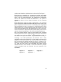
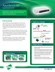
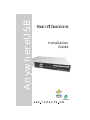
AnywhereUSB
R E M O T E I/O C O N C E N T R A T O R
Installation
Guide
AnywhereUSB
Introduction
The AnywhereUSB™ Remote I/O Concentrator is the first remote
networking solution to utilize USB Over IP™ technology, breaking the
traditional five meter distance limitation between USB device and host.
Now USB devices may be located anywhere on a wired or wireless
LAN – without a locally attached host PC. Since the host PC or server
may be located remotely, AnywhereUSB enables devices to be
deployed in harsh or non-secure environments, making it ideal for pointof-sale, kiosks, surveillance, industrial automation, or any missioncritical enterprise application. This Ethernet-attached solution provides
five USB ports to connect peripheral devices like bar-code scanners
and receipt printers, as well as our Watchport/V USB Camera and
Watchport Sensors.
Installing Drivers
For Windows XP and 2000 Users
You must install the drivers using an account that has administrative
privileges.
1. Insert the “AnywhereUSB Driver” CD into your CD drive.
2. Open the CD folder and double click on the Setup.exe program.
This installs the system driver and creates the AnywhereUSB Start
menu item.
You may proceed to the next section, “Cabling AnywhereUSB.”
Cabling AnywhereUSB
In order to configure an AnywhereUSB concentrator, it must be
connected on the same LAN subnet as the PC running the
configuration utility. Configuration will not pass through a router.
To connect your AnywhereUSB:
1. Connect one end of the power supply* into the back of your
AnywhereUSB and the other end into an AC outlet.
2. Connect a standard Ethernet network cable to your AnywhereUSB.
Then connect the other end of the Ethernet cable to a 10/100 BaseT
hub or switch.
*Power to this product may be supplied by a UL Listed Direct Plug-In Power Unit marked “Class 2” or
a UL listed power supply rated with a minimum rating of 5 V dc 2.5 A if used in the U.S. and Canada or
a power supply with similar rating and approved by your local safety code if it is used elsewhere. For
polarity, see the following: +
-
1
Configuring Your Concentrator
In order to configure your AnywhereUSB concentrator:
1. Launch the AnywhereUSB Configuration Utility from the Start
menu. The utility displays a list of discovered AnywhereUSB
concentrators on your local subnet.
Note that the concentrator must be on the same local area
network and in the same subnet as the configuration PC in order
for it to appear on the discovery list. The configuration utility will
not discover concentrators across network routers.
2. You can identify each concentrator by its serial number. Select a
concentrator and either double click or right click and select Configure
Concentrator in order to set the IP address, subnet mask, and default
gateway.
3. You must click on the Update button and reset the device in order
for the changes to take effect.
Configuring Your Host PC
In order to configure a Host PC to access the concentrator:
1. Launch the AnywhereUSB Configuration Utility from the Start
menu. The utility displays a list of all AnywhereUSB concentrators on
your local subnet.
2. Select a concentrator, right click, and select Connect to
Concentrator to add the concentrator’s IP address to the
Concentrator Connection List.
If you need to connect to a concentrator that does not show up in the
discovery list (not on your local subnet), you must select Concentrator
Connection List from the Edit menu to add the IP address of this
concentrator to your host PC.
The Concentrator Connection List editor also allows you to Add, Modify,
and Remove concentrators from this Host PC.
Uninstalling the Drivers
In order to uninstall the AnywhereUSB drivers
1. Launch the AnywhereUSB Configuration Utility from the Start
menu.
2. Select Preferences from the File menu and click on the Uninstall
button. You must reboot your PC in order to complete the driver
removal.
2
Interpreting Status Lights
The AnywhereUSB Concentrator has 6 LEDs on the front panel, the
System Status LED and 5 hub LEDs. Each LED is capable of displaying
3 colors, red, green, or orange.
System Status Lights
On initial power up the system status LED is orange for 2 seconds while
the system initializes and then blinks green.
Hub Lights
Green hunting pat- Not connected to a host.
tern across all LEDs
Orange alternating
on ports 1-3-5 and
2-4
Updating image in Flash. Do not remove power
from concentrator while flash is being updated. Doing so will damage your concentrator.
Solid Green
Device is connected to hub port.
Fast Red
Power error detected on hub port.
Slow Red
Device is connected to hub port but device error
Green over Red
hunting pattern
Please call customer service.
Using the Configuration Utility Menu
File Menu: Preferences
Allows you to disable or modify the frequency in which the utility
updates its discovered concentrator list. Enables the logging of driver
events to the system event log and allows you to uninstall the drivers
Edit: Concentrator Connection List
Contains the IP addresses of the AnywhereUSB concentrators to
which this Host PC will try to connect. When an IP address is added
to this list, the Host PC immediately tries to connect to the
concentrator. If an IP address in this list refers to a concentrator that
is connected to this PC, and that address is deleted, all USB devices
attached to this concentrator will be removed from this Host PC.
3
Concentrator: Configure Concentrator
Allows you to set up the TCP/IP parameters in the concentrator. You
also have the option to add this IP address to the Concentrator
Connection List by checking the Connect to this Concentrator box.
The debug log address refers to the IP address of a networked PC
that can be used to log debug information from the concentrator. You
must run the AwUsbLog application, located on the CD, in order to
capture the logging information.
Concentrator: Connect to Concentrator
Adds the IP address of the Concentrator to the Concentrator
Connection List.
Concentrator: Concentrator Information
Displays information about the concentrator such as: Version
numbers, IP Address and Mask.
Concentrator: Reset Concentrator
Causes the Concentrator to reboot.
View: Refresh Concentrator List
Updates the Discovered Concentrator List.
View: Driver Information
Displays the version numbers of the AnywhereUSB drivers. This
dialog also allows you to uninstall the drivers.
Understanding Hubs
Hubs, critical components in the plug-and-play architecture, are wiring
concentrators that enable the attachment of multiple devices, thus
converting a single attachment point into multiple attachment points.
USB architecture allows a cascaded multiple hub configuration with
PC
Host
Hubport
Edgeport
Hubport
Edgeport
Edgeport
bus-powered hub
joystick
Figure 1: Example of a Typical Hub Configuration
4
mouse
scanner
certain power limitations (explained later in this section). See figure 1.
Each hub has an upstream port, connecting to the host, and multiple
downstream ports, connecting to downstream devices, including other
hubs. A hub can detect attachment and detachment of downstream
devices and enable and monitor the distribution of the power to
downstream devices via their integral hardware and the operating
system.
Each USB device reports its power requirements to the operating
system, which then enables and disables the device as a function of its
power requirements and the amount of available power. High-speed
devices typically need to be connected to a self-powered hub, which
obtains power from its external power supply and provides up to 500
mA for each downstream port. Only simple devices, such as a mouse,
can be connected to a bus-powered hub, which obtains power from its
upstream host and provides up to 100 mA for each downstream port.
Due to the limited available power for bus-powered hubs, cascading
two bus-powered hubs is an illegal topology, and devices connected to
the second hub will not function. (USB specifications limit the
connection of a bus-powered hub to a self-powered hub or host only.)
According to the USB Specification, the maximum limit of hubs
cascaded in series cannot exceed five. In other words, you may have a
maximum of five hubs between any device and the host. This does
NOT mean that the maximum number of hubs in a system is five.
Indeed, up to seven hubs can be connected parallel at any given level.
You must tally both external and embedded hubs when counting
downstream hubs. Since several of Inside Out Networks’ products
contain embedded hubs, the following lists their respective “hub
equivalents.”
Edgeport/2 = 0
Edgeport/4 = 0
Edgeport/8 = 0
Edgeport/21 = 1
Edgeport/421 = 1
Edgeport/416 = 1
Edgeport/42 = 1
Edgeport/412 = 1
5
Regulatory and Other Information
Inside Out Networks and the Inside Out Networks logo are trademarks of Inside Out Networks, Inc. Digi, Digi
International, the Digi logo, the Digi Connectware logo, AnywhereUSB, USB Over IP, Watchport, Edgeport
and Hubport are trademarks or registered trademarks of Digi International, Inc. in the United States and other
countries worldwide. All other trademarks are the property of their respective owners.
Information in this documentation is subject to change without notice and does not represent a commitment
on the part of Inside Out Networks Inc.
Inside Out Networks provides this document “as is,” without warranty of any kind, either expressed or
implied, including, but not limited to, the particular purpose. Inside Out Networks may make improvements
and/or changes to this documentation or to the product(s) and/or program(s) described in this
documentation at any time.
Inside Out Networks assumes no responsibility of any errors, technical inaccuracies, or typographical errors
that may appear in this documentation, nor liability for any damages arising out of its use. Changes are
made periodically to the information herein; these changes may be incorporated in new editions of the
publication.
For U.S. Government use:
Any provision of this document and associated computer programs to the U.S. Government is with
“Restricted Rights.” Use, duplication, or disclosure by the government is subject to the restrictions set forth
in, subparagraph (c) (1) (ii) of the Rights in Technical Data and Computer Software clause of DFARS
52.277-7013.
For non-U.S. Government use:
These programs are supplied under a license. They may be used, disclosed, and/or copied only as supplied
under such license agreement. Any copy must contain the above copyright notice and restricted rights
notice. Use, copying, and/or disclosure of the programs is strictly prohibited unless otherwise provided for in
the license agreement.
Federal Communications Commission (FCC) Regulatory Information (USA only)
This equipment has been tested and found to comply with the limits for a Class B digital device, pursuant to
Part 15 of the FCC Rules. These limits are designed to provide reasonable protection against harmful
interference in a residential installation. This equipment generates, uses, and can radiate radio frequency
energy and, if not installed and used in accordance with the instructions, may cause harmful interference to
radio communications. However, there is no guarantee that interference will not occur in a particular
installation. If this equipment does cause harmful interference to radio or television reception, which can be
determined by turning the equipment off and on, the user is encouraged to correct the interference by one
or more of the following measures:
• Reorient or relocate the receiving antenna.
• Increase the separation between the equipment and the receiver.
• Connect the equipment into an outlet that is on a circuit different from the receiver.
• Consult the dealer or an experienced radio/TV technician for help.
Warning: The connection of a non-shielded interface cable to this equipment will invalidate the FCC
Certification for this device.
6
FCC Regulation - Part 15
Declaration of Conformity (DoC)
This device complies with the requirements of the
Code of Federal Regulations listed below:
EN 55022 Class B (1994 w/A1 1995)
Test
Specification
EN55024
Requirement
Electrostatic
Discharge
EN61000-4-2
+4 kV contact
+8kV air
Radiated
Immunity
EN61000-4-3
3 V/m
1. This device may not cause harmful interference,
and
Electrical
Fast Transient Burst
EN61000-4-4
1kV (A/C), .5kV (I/O)
2. This device must accept any interference received, including interference that may cause
undesired operation.
Surge
EN61000-4-5
2kV common mode
1kV differential mode
Conducted
Immunity
EN61000-4-6
3V rms
Magnetic
Immunity
EN61000-4-8
1 A/m Not Applicable
Voltage Dips
& Interrupts
EN61000-4-11
>95%, 30% & >95%
FCC Title 47 CFR, Part 15 Class B for a digital
device.
Operation is subject to the following two conditions:
Department of Communication (DOC) Notice
(Canada only)
This Class B digital apparatus meets the requirements of the Canadian Interference-Causing Equipment Regulations.
Cet appareil numérique de la Classe B respecte
toutes les exigences du Règlement sur le matériel
brouiller du Canada.
EN55024 (1998)
Test
Specification
EN55022
Requirement
European Community - CE Mark
Declaration of Conformity (DOC)
Radiated
Emissions
—
Class B
According to ISO/IEC Guide 22 and EN 45014
Conducted
Emissions
CISPR 22
Class B
Manufacturer’s Name: Inside Out Networks
Manufacturer’s Addr.:
7004 Bee Caves Rd.
Bldg. 3, Ste. 200
Austin, TX 78746 USA
declares that the product
Product Name:
Model Number(s):
AnywhereUSB
301-1130-01
Product Options:All
conforms to the relevant EU Directives listed
here:
EMC Directive 89/336/EEC |
Low Voltage Directive 73/23/EEC
Amending Directive 93/68 EEC
using the relevant section of the following EU
standards and other normative documents:
Safety:
IEC 950:1991 +A1, A2, A3, A4
EN 60950:1992 + A1, A2, A3, A4
EMC
The following summarizes the specifications and
requirements for EN55024, EN55022 Class B &
CISPR 22 Class B emission and immunity tests. If
the actual test levels are higher or different than
required, these levels are listed in the appropriate
tables.
European Contact
Digi International
Joseph-von-Fraunhofer Str. 23
44227 Dortmund, GERMANY
49-231-9747-0
UL/CSA Safety Information
This device complies with the requirements of following safety standards below:
UL 1950, 3rd edition
CSA No. 950
Quality Manager
Austin, Texas
05/03
Copyright 2003 by Inside Out Networks. All rights
reserved. Information in this documentation is subject
to change without notice and does not represent a
commitment on the part of Inside Out Networks Inc.
7
Inside Out Networks
A Digi International Company
www.ionetworks.com
7004 Bee Caves Road
Building 3, Suite 200
Austin, TX 78746
512-306-0600 ph
512-306-0694 fax
[email protected]
[email protected]
[email protected]
Digi Europe: +49-231-9747-0
Digi Hong Kong: +852-2833-1008
90000405 Rev B