1
EPSON TERMINAL PRINTER
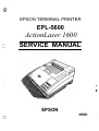
EPL-5600
ActionLaser 1600
SERVICE MANUAL
.
‘
I
,
EPSON
NOTICE
All rights reserved. Reproduction of any part of this manual in any form whatsoever without
SEIKO EPSON’s express written permission is forbidden.
The contents of this manual are subjects to change without notice.
All efforts have been made to ensure the accuracy of the contents of this manual. However, should
any errors be detected, SEIKO EPSON would greatly appreciate being informed of them.
The above notwithstanding SEIKO EPSON can assume no responsibility for any errors in this
manual or the consequence thereof.
Epson and Epson ESC/P are registered trademark of Seiko Epson corporation.
General Notice: Other product names used herein are for identication purposes only and maybe
trademarks of their respective campanies.
@Copyright 1994 by SEIKO EPSON CORPORATION Nagano, Japan
-i-
PRECAUTIONS
Precautiomry notations throughout the text are categorized relative to 1) personal injury and 2)
damage to equipment.
DANGER Signals a precaution which, if ignored, could result in serious or fatal personal injury.
Great caution should be exercised in performing procedures preceded by DANGER
Headings.
WARNING Signals a precaution which, if ignored, could result in damage to equipment.
The precautionary measures itemized below should always be observed when performing repair/
maintenance procedures.
DANGER
1.
ALWAYS DISCONNECT THE PRODUCT FROM BOTH THE POWER SOURCE AND
PERIPHERAL DEVICES PERFORMING ANY MAINTENANCE OR REPAIR PROCEDURE.
2. NO WORK SHOULD BE PERFORMED ON THE UNIT BY PERSONS UNFAMILIAR WITH
BASIC SAFETY MEASURES AS DICTATED FOR ALL ELECTRONICS TECHNICIANS IN
THEIR LINE OF WORK.
3. WHEN PERFORMING TESTING AS DICTATED WITHIN THIS MANUAL, DO NOT
CONNECT THE UNIT TO A POWER SOURCE UNTILINSI’RUCTED TO DO SO. WHEN
THE POWER SUPPLY CABLE MUST BE CONNECTED, USE EXTREME CAUTION IN
WORKING ON POWER SUPPLY AND 011-IER ELECTRONIC COMPONENTS.
WARNING
1. REPAIRS ON EPSON PRODUCT SHOULD BE PERFORMED ONLY BY AN EPSON
CERTIFIED REPAIR TECHNICIAN.
F--
4
2. MAKE CERTAIN THAT THE SOURCE VOLTAGE IS THE SAME AS THE RATED VOLTAGE, LISTED ON THE SERIAL NUMBER/RATING PLATE. IF THE EPSON PRODUCT
HAS A PRIMARY AC RATING DIFFEREM FROM AVAILABLE POWER SOURCE, DO
NOT CONNECT IT TO THE POWER SOURCE.
3. ALWAYS VERIFY THAT THE EPSON PRODUCT HAS BEEN DISCONNECTED FROM
THE POWER SOURCE BEFORE REMOVING OR REPLACING PRINTED CIRCUIT
BOARDS AND/OR INDIVIDUAL CHIPS.
4. IN ORDER TO PROTECT SENSITIVE MICROPROCESSORS AND CIRCUITRY, USE
STATIC DISCHARGE EQUIPMENT, SUCH AS ANTI-STATIC WRIST STRAPS, WHEN
ACCESSING INTERNAL COMPONENTS.
5. REPLACE MALFUNCTIONING COMPONENTS ONLY WITH THOSE COMPONENTS
BY THE MANUFACTURE; INTRODUCTION OF SECOND-SOURCE ICS OR OTHER
NONAPPRO”VED COMPONENTS MAY DAMAGE THE PRODUCI’ AND VOID ANY
APPLICABLE: EPSON WARRANTY.
,,.. . ,
- ii -
SAFETY INFORMATION
This printer is a page printer which operates by means of a laser. There is no possibility of danger from
the laser, provided the printer is operated according to the instructions in this manual provided.
Since radiation emitted by the laser is completely confined within protective housings, the laser beam
camot escape from the machine during any phase of user operation.
For United States Users;
[Laser Safety]
This printer is certified as a Class 1 Laser product under the U.S. Department of Health
and Human Services (DHHS) Radiation Performance Standard according to the Radiation Control for Health and Safety Act of 1968. This means that the printer does not
produce hazardous laser radiation.
[CDRH Regulations]
The Center for Devices and Radiological Health (CDRH) of the U.S. Food and Drug
Administration implemented regulations for laser products on August 2,1976. Compliance is mandatory for products marketed in the United States. The label shown below
indicates compliance with the CDRH regulations and must reattached to laser products
marketed in the United States.
WARNING: Use of controls, adjustments or performance of procedures other
than those specified in this manual may result in hazardous radiation exposure,
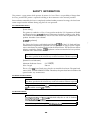
[Internal Laser Radiation]
Maximum Radiation Power:
Wave Length:
5.7x 10⁴(W)
780 nm
This is a Class IIIb Laser Diode Assay that has an invisible laser beam. The print head
unit is NOT A FIELD SERVICE ITEM. Therefore, the print head unit should not be
opened under any circumstances.
For Other Countries Users;
WARNING: Use of controls, adjustments or performance of procedures other
than those specified in this manual may result in hazardous radiation exposure,
This is a semiconductor laser. The maximum power of the laser diode is 5.7 ~
10-4 W and the wavelength is 780 nm.
For Denmark Users;
ADVARSEL
Usynlig laserstr~ling ved ~bning, niir sikkerhedsafbrydere er ude af funktion.
Undgii uds~ttelse for strWng.
Klasse 1 laser produkt der opfylder IEC825 sikkerheds kravene.
.,,
-111-
1
,,-
VAROITLJS
Laitteen Iciiyttiminen muulla kuin tiissd Idiytt50hjeessa mainitulla tavalla
saattaa altistaa ldiyttiijiin turvallisuusluokan 1 ylittiiv~lle niikyrniitt&r@le
Iasersiiteiylle.
VARNING
Orn apparaten anviinds pi% annat siitt ti i denna bruksanvisning sp-ificerats,
kan anvtidaren utstittas fdr osynlig laserstrihin~ som 6verskrider grhser
for laser klass 1.
For Norway lhwa;
ADVARSEL
Dersom apparatet brukes p~ annen rniite enn spesifisert i denne bruksanvisnins kan brukeren utsettes for unsyrrlig laserstriiling som overskrider grenser
for laser klasse 1.
Dette er en halvleder laser. Maksi@ effeckt til Iaserdiode er 5.7 x 10+ W og
,balgekngde er 7S0 nm.
Laaer Safety Labels
[Label on rear printer case]
A laser safety labels is attached on the outside of the printer shown below.
For United State
f
\
This laser product conferms to the
applicable requirement of 21 CFR
Chapter 1, subchapter J.
SEIKO EPSON CORP.
Hirooka Office
80 Hirooka, Shiojiri-shi, Nagano-ken,
JAPAN
MANUFACTURED:
J
-iv-
For Europe
/
LASER KLASSE 1 NACH IEC 825
CLASS 1 LASER PRODUCT TO IEC 825
KLASSE 1 LASER PRODUKT I.H.T. IEC 825
.w
\
[Label inside printer]
The following laser safety label will be attached inside the printer as shown below.
For Denmark, Finland, Sweden, and Nomvay
-v-
PREFACE
This manual describes functions, theory of electrical and mechanical operations, maintenance, and repair
of EPL-5600 /ActionLaser 1600.
The instructions and procedures included herein are intended for the experience repair technician, and
attention should be given to the precautions on the preceding page. The chapters are organized as
follows:
CHAPTER 1. GENERAL DESCRIPTION
Provides a general product overview, lists specifications and illustrates the main components of the printer.
CHAPTER 2. OPERATING PRINCIPLES
Describes rhe theory of printer operation.
,..
L“:”:
CHAPTER 3. DISASSEMBLY AND ASSEMBLY
Includes a step-by-step guide for product disassembly and assembly.
CHAPTER 4. ADJUSTMENTS
Includes a step-by-step guide for adjustment.
CHAPTER 5. TROUBLESHOOTING
Provides Epson-approved techniques for adjustment.
CHAPTER 6. MAINTENANCE
Describes preventive maintenance techniques and lists lubricants and adhesives required to service the equipment.
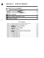
APPENDIX
Describes connector pin assignments circuit diagmrm circuit board component layout and exploded diagram.
The contents of this manual are subject to change without notice.
-
vi -
REVISION SHEET
Revision
Rev. A
Revision Page
Issue Date
Februaty
2, 1994
1st issue
i
-
. .
Vll -
TABLE OF CONTENTS
CHAPTER 1.
CHAPTER 2.
CHAPTER 3.
CHAPTER 4.
CHAPTER 5.
CHAPTER 6.
APPENDIX
GENERAL DESCRIPTION
OPERATING PRINCIPLES
DISASSEMBLY AND ASSEMBLY
ADJUSTMENTS
TROUBLESHOOTING
MAINTENANCE
-
,..
Vlll -
.
Chapter 1 General Description
Table of Contents
1.1 FEATURES
..
1-1
1-3
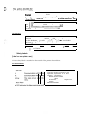
1.2 SPECIFICATIONS
1.2.1 Basic Specifications. . . . . . . . . . . . . . . . . . . . . . . . . . . . . . . . . . . . . . . . . 1-3
1.2.2 Electrical Specifications. . . . . . . . . . . . . . . . . . . . . . . . . . . . . . . . . . . . . . 1-5
1.2.3 Reliability Specifications . . . . . . . . . . . . . . . . . . . . . . . . . . . . . . . . . . . . . 1-5
1.2.4 Environmental Conditions for Operating (including Imaging Cartridge). . 1-5
1.2.5 Environmental Condifitons for Storage and Transpiration
(Excluding Image Cartridge). . . . . . . . . . . . . . . . . . . . . . . . . . . . . . . . . 1-5
1.2.6 Applicable Standards. . . . . . . . . . . . . . . . . . . . . . . . . . . . . . . . . . . . . . . . 1-6
1.2.7 Specification for Consumable (Imaging Cartridge) . . . . . . . . . . . . . . . . . 1-6
1.2.8 Physical Specifications . . . . . . . . . . . . . . . . . . . . . . . . . . . . . . . . . . . . . . 1-6
1.2.9 Software Specifications. . . . . . . . . . . . . . . . . . . . . . . . . . . . . . . . . . . . . . 1-7
1-1o
1.3 INTERFACE SPECIFICATIONS
1.3.1 Parallel Interface. . . . . . . . . . . . . . . . . . . . . . . . . . . . . . . . . . . . . . . . . . 1-10
1.3.1.1 Compatibility Mode of Parallel InterFace. . . . . . . . . . . . . . . . . . 1-10
1.3.1.2 Reverse Mode. . . . . . . . . . . . . . . . . . . . . . . . . . . . . . . . . . . . . . I-12
1.3.2 Serial Interface . . . . . . . . . . . . . . . . . . . . . . . . . . . . . . . . . . . . . . . . . . . 1-16
1.3.3 Optional LocalTalk Interface . . . . . . . . . . . . . . . . . . . . . . . . . . . . . . . . . 1-18
1-19
1.4 OPERATING INSTRUCTIONS
1.4.1 Control Panel.... . . . . . . . . . . . . . . . . . . . . . . . . . . . . . . . . . . . . . . . . . 1-19
1.4.2 SelecType Functions. . . . . . . . . . . . . . . . . . . . . . . . . . . . . . . . . . . . . . . 1-21
1.4.3 Sewice Mode. . . . . . . . . . . . . . . . . . . . . . . . . . . . . . . . . . . . . . . . . . . . . 1-24
1.4.3.1 Hexadecimal Dump Mode. . . . . . . . . . . . . . . . . . . . . . . . . . . . . 1-24
1.4.3.2 Language Setting Mode . . . . . . . . . . . . . . . . . . . . . . . . . . . . . . 1-24
1.4.3.3 Factory Sewice Mode. . . . . . . . . . . . . . . . . . . . . . . . .# . . . . . . 1-25
1.4.3.4 EEPROM Format . . . . . . . . . . . . . . . . . . . . . . . . . . . . . . . . . . . 1-25
1.4.4 Display of Messages. . . . . . . . . . . . . . . . . . . . . . . . . . . . . . . . . . . . . . . 1-26
1.4.4.1 Status Messages. . . . . . . . . . . . . . . . . . . . . . . . . . . . . . . . . . . . 1-26
1.4.4.2 Error Messages. . . . . . . . . . . . . . . . . . . . . . . . . . . . . . . . . . . 1-26
.
1.4.4.3 Warning Message. . . . . . . . . . . . . . . . . . . . . . . . . . . . . . . . . . . 1-26
1.4.5 Printer Sharing. . . . . . . . . . . . . . . . . . . . . . . . . . . . . . . . . . . . . . . . . . . . 1-28
1.4.5.1 Port Fixed Mode . . . . . . . . . . . . . . . . . . . . . . . . . . . . . . . . . . . . 1-28
1.4.5.2 Auto Sense Mode. . . . . . . . . . . . . . . . . . . . . . . . . . . . . . . . . . . 1-28
1.4.6 Emulation Mode Switch Function . . . . . . . . . . . . . . . . . . . . . . . . . . . . . 1-30
1.4.6.1 Emulation Switch by SPL . . . . . . . . . . . . . . . . . d . . . . . . . . . . . 1-30
1.4.6.2 Intelligent Emulation Switch . . . . . . . . . . . . . . . . . . . . . . . . . . . 1-30
1.4.7 Bi Resolution Improvement Technology . . . . . . . . . . . . . . . . . . . . . . . . 1-31
1.4.8 Optional Memory . . . . . . . . . . . . . . . . . . . . . . . . . . . . . . . . . . . . . . . . . . 1-32
1-33
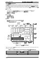
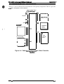
1.5 MAIN COMPONENTS
1.5.1 C125 MAIN Board . . . . . . . . . . . . . . . . . . . . . . . .‘. . . . . . . . . . . . . . . . . 1-34
1.5.2 C82326* l/F Board (Optional LocalTalk Module). . . . . . . . . . . . . . .‘. . . 1-35
1.5.3 Control Panel.... . . . . . . . . . . . . . . . . . . . . . . . . . . . . . . . . . . . . . . . . . 1-35
1.5.4 PWB-A Board.... . . . . . . . . . . . . . . . . . . . . . . . . . . . . . . . . . . . . . . . . . 1-36
1.5.5 pWB-E Board.... . . . . . . . . . . . . . . . . . . . . . . . . . . . . . . . . . . . . . . . . . 1-36
1.5.6 PWB-F Board.... . . . . . . . . . . . . . . . . . . . . . . . . . . . . . . . . . . . . . . . . . 1-37
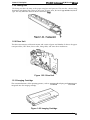
1.5.7 Optical Unit. . . . . . . . . . . . . . . . . . . . . . . . . . . . . . . . . . . . . . . . . . . . . . . 1-37
1.5.8 Fusing Unit. . . . . . . . . . . . . . . . . . . . . . . . . . . . . . . . . . . . . . . . . . . . . . . 1-38
, 1.5.9 Drive Unit . . . . . . . . . . . . . . . . . . . . . . . . . . . . . . . . . . . . . . . . . . . . . . . . 1-38
1.5.10 lrnaging Cartridge. . . . . . . . . . . . . . . . . . . . . . . . . . . . . . . . . . . . . . . . . 1-38
1.5.11 Lower Paper Cassette . . . . . . : . . . . . . . . . . . . . . . . . . . . . . . . . . . . . . 1-39
1.5.12 Face-Up Output Tray . . . . . . . . . . . . . . . . . . . . . . . . . . . . . . . . . . . . . . 1-39
List of Figures
Figure
Figure
Figure
Figure
Figure
Figure
Figure
Figure
Figure
Figure
Figure
Figure
Figure
Figure
Figure
Figure
Figure
Figure
Figure
Figure
Figure
Figure
Figure
Figure
Figure
Figure
Figure
Figure
-1.
-2.
-3.
-4.
-5.
-6.
-7.
-8.
-9.
-1o.
-11.
-12,
-13,
-14.
-15.
-16.
-17.
1-18.
1-19.
1-20.
1-21.
1-22.
1-23.
1-24.
1-25.
1-26.
1-27.
1-28.
:xterior View of the EPL-5600 and ActionLaser 1600 . . . . . . . . . . 1-1
~fintableArea. . . . . . . . . . . . . . . . . . . . . . . . . . . . . . . . . . . . . . . . . 1-4
Compatibility ModeSignalTiming. . . . . . . . . . . . . . . . J . . . . . . . . 1-10
~arallel Interface State Switch Diagram . . . . . . . . . . . . . . . . . . . . I-13
Timing Chart ofNegotiation . . . . . . . . . . . . . . . . . . . . . . . . . . . . . 1-14
Timing Chart ofDataTransfer. . . . . . . . . . . . . . . . . . . . . . . . . . . . 1-14
Timing Chart ofTermination . . . . . . . . . . . . . . . . . . . . . . . . . . . . . 1-15
Timing Chartoflnterrupt. . . . . . . . . . . . . . . . . . . . . . . . . . . . . . . . 1-15
2ontrol Panel . . . . . . . . . . . . . . . . . . . . . . . . . . . . . . . . . . . . . . . . 1-19
Port Fixed Mode. . . . . . . . . . . . . . . . . . . . . . . . . . . . . . . . . . . . . 1-28
Auto Sense Mode. . . . . . . . . . . . . . . . . . . . . . . . . . . . . . . . . . . . 1-29
Emulation Switch by SPL . . . . . . . . . . . . . . . . . . . . . . . . . . . . . . 1-30
Intelligent Emulation Switch . . . . . . . . . . . . . . . . . . . . . . . . . . . . 1-30
Effect of BiRITech. . . . . . . . . . . . . . . . . . . . . . . . . . . . . . . . . . . . 1-31
RITechAdjustment . . . . . . . . . . . . . . . . . . . . . . . . . . . . . . . . . . . 1-31
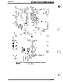
Component Layout . . . . . . . . . . . . . . . . . . . . . . . . . . . . . . . . . . . 1-33
C125 Main Board . . . . . . . . . . . . . . . . . . . . . . . . . . . . . . . . . . . . 1-34
C82326* l/F Board. . . . . . . . . . . . . . . . . . . . . . . . . . . . . . . . . . . 1-35
Control Panel . . . . . . . . . . . . . . . . . . . . . . . . . . . . . . . . . . . . . . . 1-35
PWB-ABoard . . . . . . . . . . . . . . . . . . . . . . . . . . . . . . . . . . . . . . . 1-36
PWB-E Board . . . . . . . . . . . . . . . . . . . . . . . . . . . . . . . . . . . . . . . 1-36
PWB-FBoard . . . . . . . . . . . . . . . . . . . . . . . . . . . . . . . . . . . . . . . 1-37
Optical Unit. . . . . . . . . . . . . . . . . . . . . . . . . . . . . . . . . . . . . . . . . 1-37
Fusing Unit..... . . . . . . . . . . . . . . . . . . . . . . . . . . . . . . . . . . . . 1-38
Drive Unit . . . . . . . . . . . . . . . . . . . . . . . . . . . . . . . . . . . . . . . . . . 1-38
Imaging Cartridge . . . . . . . . . . . . . . . . . . . . . . . . . . . . . . . . . . . . 1-38
Lower PaperCassette. . . . . . . . . . . . . . . . . . . . . . . . . . . . . . . . . 1-39
Face-Up Output Tray . . . . . . . . . . . . . . . . . . . . . . . . . . . . . . . . . 1-39
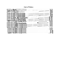
List of Tables
Table 1-1. Options for EPL-5600 and ActionLaser 1600 . . . . . . . . . . . . . . . . . 1-2
Table 1-2. Paper Feed Methods. . . . . . . . . . . . . . . . . . . . . . . . . . . . . . . . . . . . 1-3
Table 1-3. Paper Types . . . . . . . . . . . . . . . . . . . . . . . . . . . . . . . . . . . . . . . . . . 1-3
Table l-4. Usability ofSpecial Papers . . . . . . . . . . . . . . . . . . . . . . . . . . . . . . . 1-4
Table l-5. Electrical Specifications. . . . . . . . . . . . . . . . . . . . . . . . . . . . . . . . . . 1-5
Table 1-6. Differences between EPSON GIJ2 and GL/2 in the
HP LaserJet 4 Emulation. . . . . . . . . . . . . . . . . . . . . . . . . . . . . . . . . 1-7
Table l-7. Built-in Fonts . . . . . . . . . . . . . . . . . . . . . . . . . . . . . . . . . . . . . . . . . . 1-7
Table l-8. ParalleI interface Pin Assignment . . . . . . . . . . . . . . . . . . . . . . . . . 1-11
Table l-9. Parallel Interface Pin Assignment . . . . . . . . . . . . . . . . . . . . . . . . . 1-12
Table l-10. Serial Interface Pin Assignments . . . . . . . . . . . . . . . . . . . . . . . . . 1-16
Table l-11. LocalTalk Interface Pin Assignments. . . . . . . . . . . . . . . . . . . . . . 1-18
Table l-12. SelecType Functions. . . . . . . . . . . . . . . . . . . . . . . . . . . . . . . . . . 1-21
Table l-13. Factory Service Mode . . . . . . . . . . . . . . . . . . . . . . . . . . . . . . . . . 1-25
Table l-14. Status Messages. . . . . . . . . . . . . . . . . . . . . . . . . . . . . . . . . . . . . 1-26
Table l-15. Error Messages.. . . . . . . . . . . . . . . . . . . . . . . . . . . . . . . . . . . . . 1-26
Table l-16. WarningMessages . . . . . . . . . . . . . . . . . . . . . . . . . . . . . . . . . . . 1-27
Table 1-17. Differences in Components for the C125 MAIN Board . . . . . . . . 1-34
EPL-5600/ActionLaaer
1600 Service Manual
eeneral Deac@ion
1.1 FEATURES
The Epson @ EpL.5600 and the ActionLaser TM 1600 are non-impa~ page pMterS that ~rnbine a
semi-conductor laser with electro-photographic technology. These printem are small and lighc and
feature high-speed, high-resolution printing. Maintenance is very easy as a result of various
built-in diagnostic functions. The main features are:
No ozone
Printing speed — 6 ppm (pages per minute)
Resolution — 600/300 dpi (dots per inch)
Light weight — about 10 kg (22 lb.)
Small footprint
Easy maintenance
HP@ LaserJet@ 4 emulation mode
45 built-in scalable fonts (35 Intellifonts and 10 TrueType fonts)
~/p 2’” emulation
High-performance controller (the controller’s CPU is a 17.6 MHz SPARKlite (MB86930))
Bi Resolution Improvement Technology (BiRITech) refines the print quality by eliminating
jagged edges from images and characters on 600 dpi and 300 dpi printing.
Optional EPSONScript Level 2 (Postscript” compatible) module
EPSON Miao Gray Technology (EMGTech), which is available when using EPSONSaipt
Level 2 mode, refines gray scale printing to be comparable to printing on a 1200-dpi printer
Small and low-cost optional LocalTalkTM interface module
2 MB standard RAM and up to 64 MB RAM wi’h the addition of optional SIMMS
Bidirectional parallel interface
High-speed serial communication rate of 57.6K bps
High-speed parallel communication rate of approximately 400 KB/second
A multi-user, multi-emulation mode
IES (Intelligent Emulation Switch) allows switching between EPSONScript mode and another
mode
SPL (Shared Printer Language) enables switching of the printer mode by command
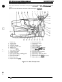
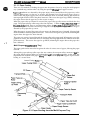
Figure 1-1 shows an exterior view of the EPL-5600 and ActionLaser 1600.
Figure 1-1. Exterior View of the EPL-5600
and ActionLaser 1600
,,./
Rev. A
1-1
EPL46W/ActionLaser 1600 Service Manual
General Description
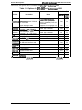
Table l-l lists the optional units available for the EPL-5600 and ActionLaser 1600.
Table 1-1. Options for EPL-5600 and ActionLaser 1600
Machine Type
Cat. No.
Note
Description
EPL-
Action~6;r
5600
EPSONScript
Level 2 mode (PostScript
Level 2 compatible) fonts and
commands
Supports local language fonts
Yes
Yes
Yes
No
Lower paper cassette
Yea
No
sUppOrtS
C83209*
—
EPSONScript Level 2 Module
~812302
Local language ROM
250 sheet lower paper
cassette for EPL-5600 (A4)
C812301
250 sheet lower paper
cassette for AL-1 600 (Letter)
Lower paper cassette
No
Yes
C81 231*
Face-up tray
—
Yes
Yes
SO51O16
C82326*
Imaging cartridge
LocalTalkT” IIF Module
Toner cartridge
—
Yes
Yes
Yes
Yes
:;:::::’
32 KB serial interface card
—
Yes
Yes
C8231
C8231 OW
,*
32 KB parallel interface card
—
Yes
Yes
C82312*
C82314*
C82315%
C82324*
LocalTalk card
COAX interface card
TWINAX interface card
Ethernet interface card for
NetWare@
—
—
Yes
Yes
—
Yes
Yes
Yes
Yes
—
Yes
Yes
Note:
1-2
LocalTalk card (C82312*) cannot use with LocalTalk I/F module (C8232@).
Rev. A
General LM.scription
EPL-5600 /ActionLaser 1600 Service Manual
1.2 SPECIFICATIONS
This section provides statistical data for the EPL-5600 and ActionLaser 1600.
1.2.1 Basic Specifications
Printing method:
Laser beam seaming and dry electro-photography
Resolution:
600/300 dpi
Printing speed:
6 ppm (letter/A4)
First printing time (A4/LT):
Less than 19 seconds (facedown output)
Less than 20 seconds (face-up output)
Warm-up time:
Less than 35 seconds
(at rated current and 23° C (73° F) temperature)
Paper supply:
See Table 1-2.
Table 1-2. Paper Feed Methods
Capacity
(20 lbh@7fm~
Paper Supply
I
Standard built-in
paper tray
Paper Size
A5, B5, A4, LT,
150
Auto feed
5 to 10
Manual feed
Lower paper cassette (optional)
;~; :~EH:GL’
,,
Monarch,
DL, C5,
Commercial-10
Usage Thickness
(Ream Weight)
I
16 to 24 lb.
(60 to 90 glm2)
Envelopes made
of 20 to 24 b. (75
to 90 ct/m2) cmer
1
Any size feedable 16 to 42 lb.
(Note 2)
(60 to 157 g/m2)
250
A4 or LT
16 to 24 lb.
(60 to 90 @m2)
Notes:
The weight in~ounds (lb) is determined by how much 500 sheets cut to 17 x 22 inch would
weigh; 1 g/m = 0.2659763 lb.
3.63 to 8.5 inches (92 to 216 mm)
2. Paper size range: width
5.85 to 14.0 inches (148.5 to 356 mm)
k?ngth
1.
(’ :
Paper types:
See Table 1-3.
Table 1-3. Paper Types
Standatd paper
Normal paper
Special papers
Rev. A
Xerox” 4024 DP paper
20 lb. (75 @m2)
] Regular photocopier paper
Bond paper
Recycled paper
16 to 24 lb. (60 to 90 g/m2)
Card stock (90 to 157 g/m2)
Envelopes
Labels
Letterhead
Transparency (OHP) sheets
Colora4 naner
1-3
EPL-6600/ActionLaser
General Description
1600 Service Manual
See Table 1-4.
Usability of special papers:
Table 1-4. Usability of Special Papers
Input
output
OHP
Envelopes
Labels
Card Stock
Letterhead
Standard
built-in paper
tray
Face down
P
P
P
P
R
Face up
R
R
R
R
R
Lower paper
cassette
Face down
Face up
N
N
N
N
P
N
N
N
N
P
R: Reliable feeding and good image quality.
P: Possible, but better avoided.
N: Not supported.
Paper feed alignment and direction:
Paper ejection:
Output tray capacity:
Center alignment for all sizes
Face down; face up (optional)
100 sheets (face down)
20 sheets (face up) (standard paper)
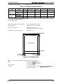
Printable area (standard paper):
See Figure 1-2.
—
Printable Area
—
4.Omm
—
4.0mm+
—
Figure 1-2. Printable Area
Note:
Noise:
The actual printable area depends on the printer mode.
Less than 35 dB(A), (standby)
Less than 47 dB(A) (operating)
Ozone density:
Toxicity:
1-4
Less than 0.01 pprn
No toxicity exists in organic photoconductor (OPC), toner,
or plastic materials
Rev. A
General Description
EPL-5600 /ActionLaser 1600 Sawice Manual
1.2.2 Electrical Specifications
Table 1-5. Electrical Specifications
I
Description
I Rated voltaae
Input voltage range
100 V Version
I
100-120 VAC
90-132 VAC
Rated frequency range
I
lnPUtfWUen~YranW
I
200 V Version
I
220-240 VAC
I
198-264 VAC
I
50-60 tiz
47-63
(
I
I
tiz
Power consumption
Less than 500 W
Less than 600 W
Power consumption while
in standby mode
Less than 30 W
(without optional interface card and font cartridge)
I
1.2.3 Reliability Specifications
MPBF (Mean Prints Between Failures): Over 25,000 sheets
Note:
,.-.,
i.
\,ti.
MPBF indicates average number of pages printed before occurrence of problem requiring
replacement or service.
MTBF (Mean Time Between Failures): 3000 Power on hours (POH)
Jam rate:
1 out of 2,0(XI sheets or less (excluding multiple-sheet feeding)
1 out of 2,tHXl sheets or less (excluding multiple-sheet feeding)
Feed failure:
Multiple paper feeds:
1 out of 5W sheets or less
Paper curl height:
30 mm (1.2 inches) or less
Leading edge bending (1 cm or more): 1 out of 1,000 sheets
MTTR (Mean Time To Repair):
30 minutes or less
Durability:
5 years or 180,01M(I sheets
1.2.4 Environmental Conditions for Operating (Including Imaging Cartridge)
‘.. .
Temperature:
10 to 35° C (50 to 95° F)
Humidity:
15 to 85’340 RH
Altitude:
2500 m (8200 feet) or lower
Levelness:
Printer should be installed on a level plane.
Illuminance:
3,000 Iux or less (Must not be exposed to direct sunlight.)
Surrounding space:
Printer should have at least 100 mm of clearance on its
sides and rear.
1.2.5 Environmental Conditions for Storage and Transportation
(Excluding Imaging Cartridge)
Temperature:
O to 35° C (32 to 95° F) over full storage term
-20 to 55° C (-4 to 131° F) under extreme conditions
(Extremes are allowable for up to 1/30 of full storage term)
Temperature variation must be 10” C (18° F)/hour or less
Humidity:
30 to 85Y0 RH over full storage term
10 to %O/. RH under extreme conditions
(Extremes are allowable for up to 1/30 of full storage term)
Drop test:
Vibration:
Clear to JIS Z0200-1987 Level 1
Vibration frequency
5 to 1(XI Hz and 100 to 5 Hz
IG
Acceleration
Acceleration direction 3 direction
Resistance to atmospheric pressure:
More than 613 mb
Storage term:
24 months (following date of manufacture)
Rev. A
14
EPL4i600/ActionLaser
General Description
1600 Service Manual
1.2.6 Applicable Standards
Safety Standards
120 VAC model:
220/240 VAC model:
UL 1950, CSA 22.2 N0.950 Deviation 3
EN 60950 (IEC950), NEMKO (IEC950), SETI (IEC950),
SEMKO (IEC950), DEMKO (IEC950)
Safety Regulations (Laser radiation)
120 VAC model:
220/240 VAC model:
FDA (NCDRH) Class 1
VDE 0837 (Laser Class 1)(IEC825), SETI (IEC825), SEMKO
(IEC825), DEMKO (IEC825)
EMI
120 VAC model:
220/240 VAC model:
FCC Part 15 Subpart B Class B
Vfg 243 (VDE 0878 Part 3s0)
EN55022 class B (CISPR Pub.22 class B)
Others
Toner:
OPC:
Ozone:
Materials:
No effect on human health (OSHA-TSCA, EINECS)
No effect on human health (OSHA)
Less than 0.01 mrnp
other UL478 (5th edition)
SWISS Environmental Law (No CdS must be contained)
1.2.7 Specification for Consumable (Imaging Cartridge)
Life:
Note:
6,000 pages
In continuous printing mode with A4/letter paper at a 5% image ratio (black/white
ratio). The life varies, depending on the printing mode (continuous or intermittent)
and/or the image ratio.
Environmental Conditions for Storage and Transpotiation
Temperature:
O to 30° C (32 to 86° F) over full storage term
–20 to 40° C (-4 to 104” F) under extreme conditions
(Extremes are allowable for up to 1/30 of full storage term)
Temperature variations must be 10° C (18° F)/hour or less.
Humidity:
30 to 857. RH over full storage term
10 to 95y0 RH under extreme conditions
(Extremes are allowable for up to 1/30 of full storage term)
Drop test:
Vibration:
Resistance to atmospheric pressure:
Storage term:
Height 76 cm (30.4 inches)
Same as printer
More than 740 mb
18 months (following date of manufacture)
1.2.8 Physical Specifications
Dimensions (Width x Depth x Height):
Printer:
With lower cassette:
With face-up tray:
With lower cassette and face-up tray:
Weight:
With lower cassette:
With face-up tray:
With lower cassette and face-up tray:
1-6
368 x 456 x 226 mm (14.5 x 18.0x 8.9 inches)
368 x 480 x 336 mm (14.5 x 18.9x 13.2 inches)
368 x 632 x 360 mm (14.5 x 24.9 x 14.2 inches)
368 x 657 x 430 mm (14.5 x 25.9 x 16.9 inches)
Approx. 10 Kg (22 lb.) (consumable, excluding all options)
Approx. 12.8 Kg (28.3 lb.)
Approx. 10.1 Kg (22.3 lb.)
Approx. 12.9 Kg (28.6 lb.)
Rev. A
General ascription
EPL4600 IActionLaser 16tM Service Manual
1.2.9 Software Specifications
HP LaserJet 4 emulation (pCL@ Se)
EPSON GL/2 mode (LJ4-GL/2 mode and GL-like mode)
FX (FX-670/1170, LX-1OO) emulation mode
ESC/P 2 (LQ-570/1070) mode
Built-in modes:
Note:
The EPSON GL/2 mode is similar to the GL/2 mode included in the HP LaserJet 4
emulation. Table 1-6 shows the differences between EPSON GL/2 mode and the GL/2
mode in the HP LaserJet 4 emulation. While in EPSON GL/2 mode, the operator can
enter GL/2 mode without sending the ESC %#B (Enter GL/2 mode) command. If the
operator’s application software cannot send the ESC %#B cmnrnan d, then use this mode.
Table 1-6. Differences between EPSON GU2 and
GL/2 in the HP LaserJet 4 Emulation
EPSON GU2 Mode
t
,,‘.
. .
GIJ2 for HP LaserJet 4
Emulation Mode
PCL mode
I Does not exist
Paper eject
I Supports PG, AF commands
I Exists as the initial made
I Supported in PCL
Auto eject
I SelecType setting
I Not available
Reduced printing
Switch to PCL
(ESC %#A)
I SelecType setting
I Available in PCL
,
Not Sllppdt?d
supported
Reset (ESC E)
Ejects paper, switches to PCL,
Ejects paper and then initializes ad
then init@[iz~
PJL. EJL. and ES
&JDDOdEd
sUDDOlkd
Advance Full Page
(PG, AF)
supported
Not supported
Notes: EPSON GL/2 mode has two operatioml modes. One is LJ4-GL/2 mode; the other is th
GL-like mode.
LJ4-CX2 mode emulates the GL/2 mode in the HP LaserJet 4 emulation. The user can
print with software that supports me HP 7600 series plotter.
The GL-like mode features all the commands of the LJ4-GL/2 mode, plus a few
additional comman ds. The GL-like mode emulates some of the HP~L@ plotter
(HP 7475A, etc.) commands. If the application software uses unsupported comman ds fir
the GL4ike mode, print cannot be assured.
EPSONScript Level 2 (PostScript Level 2 emulation) mode
Optional modes:
‘.
Auxiliary software: Hex dump
Status sheet
Font sample
Built-in tints:
See Table 1-7
Table 1-7. Built-in Fonts
Applicable Mode
Resident Fonts
Bitmap fonts
Line Printer
Prestige
Prestiae
16.66cpi (Portrait)
(Portrait)
12 cpi
(Portrait)
20 cmi
H~P# E~@ 2
s
NS
NS
NS
s
s
FX
NS
s
s
S: Supported, NS: Not Supported
,.
Rev. A
1-7
EPL-5600/ActitmLaser
General Descrit2tion
1600 Service Manual
Table 1-7. Built-in Fonts (Con’t)
Applicable Mode
Resident Fonts
Scalable fonts
Dutch’” 801
Dutch 801
Dutch 801
Dutch 801
Zapf Humanist 601
Zapf Humanist 601
Zapf Humanist 601
Zapf Humanist 601
Ribbon 131
Clarendon
Swiss’” 742
Swiss 742
Swiss 742
Swiss 742
Swiss 742
Swiss 742
Swiss 742
Swiss 742
Incised 901
Incised 901
Incised 901
Original Garamond
Original Garamond
Original Garamond
Original Garamond
Audrey Two
Flareserif 821
Flareserif 821
Swiss 721
Swiss 721
Swiss 721
Swiss 721
Dutch 801
Dutch 801
Dutch 801
Dutch 801
Symbol Set
More WingBats
Courier
Courier
Courier
Courier
Letter Gothic
Letter Gothic
Letter Gothic
Roman SWC
Bold SWC
Italic SWC
Bold Italic SWC
Demi SWC
Bold SWC
Demi Italic SWC
Bold Italic SWC
Swc
Condensed SWC
Swc
Bold SWC
Medium Italic SWC
Bold Italic SWC
Condensed SWC
Bold Condensed SWC
Condensed Italic SWC
Bold Italic Condensed SWC
Swc
Black SWC
Italic SWC
Swc
Bold SWC
Italic SWC
Bold Italic SWC
Swc
Swc
Extra Bold
Roman SWM
Bold SWM
Oblique SWM
Bold Oblique SWM
Roman SWM
Bold SWM
Italic SWM
Bold Italic SWM
SWA
SWM
Swc
Bold SWC
Italic SWC
Bold Italic SWC
Roman SWC
Bold SWC
Italic SWC
H~#4 EsC/p 2
FX
s
s
s
s
s
s
NS
NS
NS
NS
NS
NS
NS
NS
NS
NS
NS
NS
s
s
s
NS
NS
NS
NS
NS
NS
s
s
s
NS
NS
NS
NS
NS
NS
s
s
s
s
s
s
s
s
s
s
s
s
s
NS
NS
NS
NS
NS
NS
NS
NS
NS
NS
NS
NS
NS
NS
NS
NS
NS
NS
NS
NS
NS
NS
NS
NS
NS
NS
s
s
s
NS
NS
NS
NS
NS
NS
s
s
N S
NS
s
NS
NS
NS
NS
N S
s
s
s
NS
NS
NS
s
s
NS
NS
NS
NS
s
NS
NS
s
s
s
s
s
s
s
s
s
NS
NS
s
s
s
s
s
NS
NS
s
s
s
s
s“
s
s
s
S: Supported, NS: Not Supported
1-8
Rev. A
EPL-5600 /ActionLaser 1600 Service Manual
General Description
Font Symbol Sets
HP LaserJet 4 Mode (bitmap fonts): 15 symbol sets
Roman-8
Roman Extension
ECM94-1
ANSI ASCII
French2
Legal
IBM@-US
PcMultilingual
Norwegl
Italian
Swedis2
LJK
German
Spanish
IBM-DN
HP LaserJet4 Mode (scalable fonts): 34 symbol sets
Ronam-8
Italian
Swedis2
UK
German
8859-2 1S0
PsMath
WiTurkish
VeMath
Math-8
PcTk437
PsText
IBM-DN
PcMultilingual
VeUS
PcE.Europe
WiAnsi
Norwegl
ECM941
ANSI ASCII
French2
Legal
Spanish
8859-9 IS0
MsPublishing
DeskTop
WiE.Europe
Windows
IBM-US
McText
VeInternational
PiFont
symbol
Wingdings
ESC./P 2 Mode: 15 International characters and 9 code tables
USA
FRANCE
GERMANY
UK
DENMARK1
SWEDEN 1
ITALY
LEGAL
SPAIN1
JAPAN
NORWAY
DENMARK2
SPAIN2
L.AMERICA
KOREAR
PcUSA(437)
PcPortuguese(860)
PcNordic(865)
PcE.Europe(852)
BpAbicomp
PcMuItiIingual(850)
TPcCanFrench(863)
PcTurk2(857)
BpBRASCII
FX Mode: 13 International characters and 9 code tables
USA
FRANCE
GERMANY
UK
DENMARK1
SWEDENT
ITALY
SPAIN1
JAPAN
NORWAY
DENMARK2
SPAIN2
L.AMERICA
PcUSA(437)
PcPortuguese(860)
PcNordic(865)
PcE.Europe(852)
BpAbicomp
PcMultilingual(850)
P&mFrench(863)
PcTurk2(857)
BpBRASCII
Rev. A
1-9
EPL-5600 /ActionLaser 1600 Service Manual
General Description
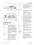
1.3 INTERFACE SPECIFICATIONS
The EPL-5600 and ActionLaser 1600 are equipped with the following external interfaces:
■ Parallel interface
■ RS-232C/RS-422 interface
■ Optional LocalTalk interface
■ Optional Type B interface
1.3.1 Parallel Interface
The parallel interface has two modes as follows:
S Compatibility mode (same as parallel interface of EPSON’s current page printer)
■ Reverse mode
1.3.1.1 Compatibility Mode of Parallel Interface
System:
STROBE synchronization, 8-bit parallel data transfer
Handshaking:
BUSY and ACKNLG signals
Connector type:
P90-25027-1 (Amphenol) receptacle
Applicable plug:
57-30360 (Amphenol or equivalent)
Transfer speed:
Approximately 400,000 bytes/second (max.)
Signal timing:
See Figure 1-3.
Signal description:
See Table 1-8.
0.5 ps
0.5 ps
(minimum) (minimum)
~+—–+
I
\
DATA 1-8
VALID
/
,
L
~ 0.5 US (minimum)
\-
/
STROBE
0.5 ps (maximum)
+ k
BUSY
-..
0s
0.5 or 5 l.lS (min.)
(minimum)
4
+-
ACKNLG
1 or 10 ps
(typical)
Figure 1-3. Compatibility Mode Signal Timing
1-1o
Rev. A
,
EPL-561W/ActionLaser 16tW Service Manual
General Description
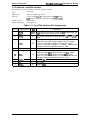
Table 1-8. Parallel Interface Pin Assignment
Pin No.
1
STROBE
Vo
Description
IN
STROBE is a strobe pulse used to read data from the host
computer. The pulse width must be more than 0.5 psec.
Normally it is HIGH, and data is latched at the trailing edge of
this signal.
DATA 1-8
IN
10
ACKNLG
OUT
11
BUSY
OUT
The BUSY signal informs the host computer of the printer
state. When the signal is HIGH, the printer cannot accept
data.
12
PE
OUT
The PE signal indicates paper empty for the standard tray
selected through SelecType or command, or for the optional
paper cassette. Paper empty is indicated by HIGH.
13
SLCT
AUTO-FEED
NC
OUT
Use at reverse mode.
14
15
16
,.
DATA 1 to 8 are pa~llel data bits. When the signal is HIGH,
the data bit is 1, and when it is LOW, the data bit is O.
The most significant bit (MSB) is DATA8. The signal state
must be maintained for 0.5 psec. on either side of the
STROBE signal active edge.
ACKNLG is an acknowledge pulse with an approximate width
of 1 or 10 wee. This signal goes LOW when the data
reception is completed, which indicates that the printer can
accept new data. Timing with the BUSY signal is specified
through SelecType.
2-9
‘-’
<
(’
Signal Name
IN
.
GND
Not USd.
Not USed.
Logic ground level.
17
CHASSIS GND
-
Connected to the printer chassis. The printer chassis GND
and the signal GND are connected to each other.
18
NC
.
Not connected.
19-30
GND
31
INIT
Ground level for the twisted pair return signal.
IN
The STROBE signal is ignored when this signal is LOW.
This level goes LOW when the printer is:
● out of paper
. paper jam
. in error state
. off line
32
ERROR
33
GND
.
Same as for pins 19 to 30.
34
NC
.
35
+5
Not USEd
Pulled up to +5V through 1.0 Kohm resistance.
36
sLCT IN
.
Use the reverse mode.
OUT
““
..,
Rev. A
1-11
EPL-5600/ActionLaser 1600 Service Manual
General Description
1.3.1.2 Reverse Mode
The reverse mode for EPL-5600/ActionLaser 1600 supports the nibble mode of IEEE-P1284. This
printer can run in reverse mode, in which the printer can inform the computer of its status by EJL
and PJL commands.
System:
Nibble mode of IEEE-P1284
Connector type:
P90-25027-1 (Amphenol) receptacle
Applicable plug:
57-30360 (Amphenol or equivalent)
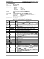
Signal description:
See Table 1-9.
Table 1-9. Parallel Interface Pin Assignment
Pin No.
Signal Name
I/o
1
STROBE
IN
2-9
DATA 1-8
IN
10
ACKNLG
11
BUSY
OUT
OUT
12
PE
13
SLCT
14
AUTO-FEED
IN
15
-
16
NC
GND
17
CHASSIS GND
-
18
19-30
31
NC
GND
INIT
32
ERROR
33
GND
.34
35
36
1-12
NC
OUT
OUT
.
IN
OUT
HostClk: This signal is a strobe pulse used to read extension
request values from the host computer during negotiation.
The signals are data bits of extension request values during
negotiation. This printer supports following values:
0000 0100: Request Device ID (by nibble mode sending)
0000 0000: Request nibble mode
PtrClk: Printer data sending clock.
PtrBusy: Printer sending data bits 3 and 7 during data
transfer to host computer.
AckDataReq: Printer sending data bits 2 and 6 during data
transfer to host computer.
Xflag: Printer sending data bits~ and Sduring data transfer to
host computer.
HostBusy: This signal informs the printer of the host computer
state. When the signal is HIGH, the host computer cannot
accept data.
Not US6?d.
Logic ground level.
Connected to the printer chassis. The printer chassis GND
and the signal GND are connected to each other.
Not connected.
Ground level for the twisted pair return signal.
nlnit: High level fixed
nDataAvail: Printer sending data bits O and 4 during data
transfer to host computer.
Same as for pins19 to 30.
.
+5
SLCT IN
Description
IN
Not U%?d.
Pulled up to +5V through 1.0 Kohm resistance.
1284Active: If this signal is set to HIGH, this printer active
P1 284 (reverse mode).
Rev. A
Generai Description
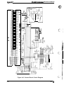
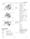
EPL-5600 /ActionLaaer 1600 Service Manuai
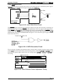
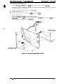
Figure 1-4 shows the parallel interface state switch diagram.
o-
Compatibility Mode
1
1O”s Q
TROBE
Forward
Data
Transfer
Forward
ACK and BU~Y
A
SLCT IN=HIGH
ERR=HIGH
Terminate
Idle
Failed
Negotiation
No data sent
SLCT IN= LOW
ERR= LOW
Sending data
I
ER R= LOW
Sending data
AUTO
FEED = LOW
Request to
send data
AUTO
FE ED= LOW
AUTO
FE ED=HIGH
FRR=LOW
Figure 1-4. Parallel Interface State Switch Diagram
Rev. A
1-13
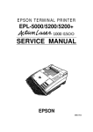
EPL-5600/ActionLaser 1600 Sarvice Manual
General Description
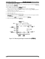
Figure 1-5 shows the timing chart of negotiation.
x - ,
OOh or 04 h
DATA
SEL-IN
STROBE
AUTO-FEED
ACKNLG
Peripheral Busy Status
BUSY
PE
~ Current Peripheral $tatus /
\
;
\
I Note 2 i
\
;
—.
SLCT
ERROR
~ Current Peripheral Status /
Notel
u
A,A
—
Notel
:
Negotiation
Compatibility
;
1
h,A
—
HB DA or : Idle or
Transfer
HB DNA
(Note 3)
Figure 1-5. Timing Chart of Negotiation
Note 1: The signal is set to HIGH when not sending data.
The signal is set to LOW when sending data.
Note 2: The signal is set to HIGH, if extension request value was 04h.
Note 3: HB DA: Host Busy Data Available
HB DNA: Host Busy Data Not Available
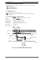
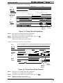
Figure 1-6 shows the timing chart of data transfer.
DATA
SEL-IN
STROBE
AUTO-FEED
\
ACKNLG
‘“L-J
—
\
2
X Peripheral ~Busy Status
Bit 3
Bit 7
PE
Bit 2
Bit 6
Njte 1 ;
SLCT
Bit 1
Bit 5
Note 2 !
BUSY
ERROR
Peripheral Busy Status X
$
/
Bit O
Bit 4 Y Note 1 ;
/
——————
—
M
HB DA
Negotiation
HB DA or
HB DNA
(Note 3)
Figure 1-6. Timing Chart of Data Transfer
Note 1: The signal is set to HIGH when not sending data.
The signal is set to LOW when sending data.
Note 2: The signal is set to HIGH, if extension request value was 04h.
Note 3: HB DA: Host Busy Data Available
HB DNA: Host Busy Data Not Available
1-14
Rev. A
Ganaralihactipthn
EPL-5600 /ActionLaaar 1600 Service Manual
Figure 1-7 shows the timing chart of termination.
DATA
SEL-IN
STROBE
N o t e 3 ~—~
AUTO-FEED
ACKN LG
,/
BUSY
Peripheral Busy St~lus /
PE
.
SLCT
Note 2
ERROR
Note
,., -,
......
Note
1
;
1
I
HB DNA, Idle,
or HB DA
1
\ Peripheral Busy Status
; Current Peripheral Status
I Current Peripheral Status
\
/
H
:
b-
Termination
Compatibility
Figure 1-7. Timing Chart of Termination
Note 1: The signal is HIGH when FIB DNA.
The signal is LOW when HB DA.
Note 2: The signal is set to HIGH, if extension request value was 04h.
Note 3: Idle = LOW
Figure 1-8 shows the timing chart of interrupt.
DATA
SEL-IN
STROBE
AUTO-FEED —
ACKNLG
BUSY
.—
~ Peripheral Busy Status !
PE
SLCT
Note
1
;
ERROR
\
Reverse
Idle
;
Interrupt
HB DA
‘ Transfer
Figure 1-8. Timing Chart of Interrupt
Note 1: The signal is set to HIGH, if extension request value was 04h.
Rev. A
1-15
EPL-6600/ActionLaser 1600 Service Manual
General Description
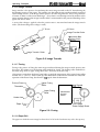
1.3.2 Serial Interface
Type:
Transfer system:
Synchronization:
Protocol:
Transfer speed:
Error:
Signal description:
RS-232C/R%122
Full duplex
Asynchronous start-stop system
1 bit
Start-bit:
1 or 2 bits
Stop-bit:
7 bits or 8 bits
Data length:
Parity:
Odd, even, or none
X-ON/X-OFF (can be combined with DTR control)
DTR control (can be combined with X-ON/X-OFF)
300,600,1200,2400,4800, 9600,19200, 384KI, or 57600 bps
Precessed as missing data and replaced by “*”
Overrun error:
Replaced by “*”
Parity error:
Replaced by “*”
Framing error:
Breaking character: Ignored
See Table 1-10.
Table 1-10. Serial Interface Pin Assignments
Pin No.
Signal Name
Vo
Description
1
CHASSIS-GND
-
Connected to the printer chassis. The printer chassis GND
and the signal GND are connected to each other.
2
TXD
3
RXD (RXD+)
4
RTS
5
CTS
~“T
IN
OUT
Always ignored.
IN
Signal input to the printer.
The printer can transmit data through TXD while DSR is at
HIGH level. X-ON/X-OFF, however, can be transmitted
regardless of DSR state. It can always be ignored by setting
SelecType (factory setting).
DSR
7
SIGNAL-GND
8
9
DCD
(SD+)
IN
OUT
10
(SD-)
OUT
20
21-25
1-16
DTR
NC
Transmission request signal output from the printer. It is
always at HIGH level during power ON.
IN
6
I 1 to 17 NC
18
(RD-)
19
NC
Serial ASCII data output by the printer. It maintains “MARK”
state (LOW level) between transmitted character codes.
Logic O is at HIGH level (“SPACE”) and logic 1 is at LOW
level (“MARK’).
Serial ASCII data input to the printer. It maintains “MARK”
state (LOW level) between received character codes.
IN
Ground.
Always ignored.
See note 4.
See note 4.
No connect.
See note 4.
No connect.
OUT
Signal output by printer. When the DTR signals HIGH, the
RXD signal can be received by the printer. The SelecType
settings do not specify DTR control, the signal level is HIGH
while the printer power is on. When SelecType setting is used
for DTR control, DTR goes LOW in case of any error
conditions.
The data (RXD) from host computer must be stopped within
128 characters after DTR goes LOW.
No connect.
Rev. A
EPL-S600 /ActionLasef 1600 Sewice Manual
General Lhwetiption
Note 1: ( ) indicates an R%122 signal, which is SPlecType.
Note 2: “CT’S’, “DSR”, and “DTR” states can be selected through SelecType.
Note 3: Although the signals RTS, Cl%, DSR, Dl% and DCDare RS-232C level, they can be used
for RS-422 mode if selected through SelecType.
Note 4: SD+, SD-:
Serial ASCII data output from the printer.
HIGH level; when SD+ voltage is higher than SD-voltage.
LOW level; when SD+ voltage is less than SD- voltage.
Logic O is “SPACE” and logic 1 is “MARK” state must be maintained between
transmitted character codes.
RD+, RD-:
Serial ASCII data input from the computer.
HIGH level; when RD+ voltage is higher than RD- voltage.
LOW level; when RD+ voltage is less than RD- voltage.
Logic O is “SPACE” and logic 1 is “MARK” state must be maintained between
transmitted character codes.
Handshaking
When the vacant area for data in the input buffer drops to 256 bytes, the printer outputs an X-OFF
code or sets the DTR signal level to LOW, indicating that the printer cannot receive more data.
Once the vacant area for data in the buffer recovers to 512 bytes, the printer outputs an X-ON code
or sets the DTR flag to HIGH, indicating that the printer is again ready to receive data.
Protocol
There are two types of protocols, as listed below, and each of them can be designated by SelecType
independently.
9 DTR/DSR protocol
SelecType is used to execute the DTR/DSR control protocol. l%e DTR signal is set to HIGH when
the printer is ready to receive data, and to LOW when conditions indicate an error or that the
receiving buffer is full.
When the error is cleared and the printer returns to on-line mode, the signal returns to HIGH.
When SelecType is used to set the DTR control OFF, DTR is always set HIGH. The printer transmits
TXD only when DSR is at the HIGH level (DSR is always considered HIGH when the SelecType
setting for DSR is OFF). X-ON/X~FF transmission is independent of the DSR state.
9 X-ON/X-OFF (DC1/DC3) protocol
SelecType is used to execute the X-ON/X-Ow protocol. The X-OFF (DC3) code is output if status
indicates an error, and the printer warns the host to stop data transmission within 128 characters.
No further X-OFF codes are sent in response to additional data received from the host after the
X-OFF code has been sent once. The X-ON (DCl) code is output after all conditions given in the
error are cleared.
When the remaining capacity of the receive buffer reaches 256 characters, X-OFF (DC3) is output
once. It is sent only once, even if there are multiple errors. The printer goes on line automatically at
power on, and outputs an X-ON code. Transmission of X~N/X-OFF codes can be defined by
SelecType.
Rev. A
1-17
EPL4600/ActionLaser 1600 Service Manual
General Description
1.3.3 Optional LocalTalk Interface
This printer can use the optional LocalTalk interface module.
Signal level:
Protocol:
LocalTalk
Same as 179422 signal level
X-ON/X-OFF (cannot be combined with DTR control)
DTR control (cannot be combined with X~N/X43FF)
Transfer speed:
230.4 K bps
Signal description:
See Table 1-11.
Type:
Table 1-11. LocalTalk Interface Pin Assignments
Pin No.
1-18
Signal Name
I/o
Description
~uT
Signal output by the printer. When the DTR signals HIGH, the
RXD signal can be received by the printer.
The printer transmits the data through TXD while CTS is
HIGH.
Serial ASCII data output from the printer.
HIGH level; when SD+ voltage is higher than SD- voltage.
LOW level; when SD+ voltage is less than SD- voltage.
Logic O is “SPACE” and logic 1 is “MARK” state must be
maintained between transmitted character codes.
1
DTR
2
CTS
IN
3
TXD-
OUT
4
GND
5
RXD-
IN
6
TXD+
OUT
7
8
NC
RXD+
Ground.
Serial ASCII data input from computer.
HIGH level; when RD+ voltage is higher than RD- voltage.
LOW level; when RD+ voltage is less than RD- voltage.
Logic O is “SPACE” and logic 1 is “MARK” state must be
maintained between transmitted character codes.
Refer to TXD-.
No connect.
IN
Refer to RXD-.
Rev. A
General Lhwctiption
EPL-5600 /ActionLaser 16tW Servkw Manual
1.4 OPERATING INSTRUCTIONS
,f%??>
,f.w:.:
~.y
This section desaibes the functions performed through the control panel, such as test print,
hexadecimal dump, and SelecType functions.
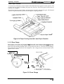
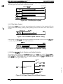
1.4.1 Control Panel
The printer control panel gives you easy control over most common printer operations. ‘Me panel
consists of a liquid aystal display (LCD), indicator lights, and buttons.
SelecType
Item
Menu
u
On Line
mu
Tti$::SW3
.......
. . . . . . . . . . k??i@iti
n
tEwil#
......
n
o
Figure 1-9. Control Panel
Display (LCD)
A 20-character (5 x 7 dot matrix) by l-row liquid crystal display (LCD) unit that indicates printer
status. A variety of printer parameters can be displayed and set using SelecType mode.
Indicator lights
■ On Line
--~..
ON:
Communication with the host is possible.
OFF:
Flashing:
Communication with the host is not currently possible.
This state occurs when the system cannot shift from off line to on line, or vice
versa.
■ Form Feed
This LED indicates the data processing condition for each interface channel: S, P, and O.
ON:
OFF:
Received data is stored in the printer but has not been printed.
There is no printable data remaining in the printer.
Flashing:
The printer is processing data.
H Continue
Flashes when an error is detected or a maintenance procedure is needed. An error message appears
on the display at the same time.
Rev. A
1-19
General Description
EPL&6001ActionLaser 1600 Service Manual
Buttons
■ ON LINE
■ Manual
(ON LINE + ALT)
■ ITEM
■ Paper Size
(ITEM+ ALT)
Enters SelecType mode.
Changes the item in SelecType mode.
Enters directly (short cut) to the paper size setting of the standard
and optional paper tray in PRINTING MENU of SelecType.
(MENU+ ALT)
Enters SelecType mode.
Changes the menu @ SelecType mcde.
Enters directly (short cut) to the paper tray select setting in
CONFIG MENU of SelecType.
ALT
Modifies the function of other buttons.
■ MENU
■ Tray Select
■
Switches the printer between on-line and off-line mode. While in
SelecType mode, this button exits SelecType mode.
Enters directly (short cut) to manual feed; this setting is the same as
the manual setting in the PRINTING MENU of SelecType.
■ ’r
Changes to the next available option of SelecType.
■ ~ (~+ ALT)
Changes to the previous available option of SelecType.
■ ENTER
Sets available option of SelecType.
■ FORM FEED
When the printer is offline and the Form Feed light is lit, pressing
this button prints out data in the printer’s memory.
Pressing this button when the Continue light is flashing clears an
error.
Enter to reset operation; LCD displays “RESET”, printing stops, and
the input buffer of current interface is cleared.
■ CONTINUE
■ RESET
(CONTINUE + ALT)
If the RESET button is depressed continuously after “RESET” is
displayed, the message displayed on the LCD changes to “RESET
ALL” (about 5 seconds), and the printer enters to WARM BOOT
operation; printer clears all RAM.
1-20
Rev. A
Generai Wription
EPL-66(W/ActionLaser 1600 Sendce Manuai
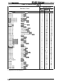
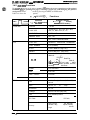
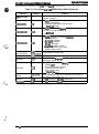
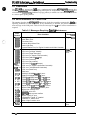
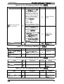
1.4.2 SelecType Functions
The SelecType function on the printer control p~el allows the user to control most of the printer’s
functions, su&I as printing test pages, selecting a paper size, and changing the printer’s
configuration. Enter SelecType mode by pressing the MENU or ITEM button.
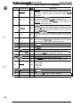
Table 1-12 shows the SekcType options.
Tabie 1-12. SelecType Functions
Available Optima
(Chan ad by f’or~ button)
(Set$y ENTER button)
Menu
(Changed::)MENU (chan@ &~EM button)
PRINTING
LJ4
(Ps)
ESCP2
COPIES
1 to 999
PAGE SIZE
A4, A5, B5, LT, HLT, LGL, GLT, GLG,
EXE, F4, MON, C1O, DL, C5, IB5
ORIENTATION
PORT, LAND
MANUAL FEED
OFF, ON
R!Tech
OFF, LIGHT, MEDIUM, DARK
FONT SRC
RESIDENT, CARTRIDGE, DOWNLOAD
FONT NUMBER
O to (available)
PITCH
0.44 to 99.99 CPI (step 0.01)
HEIGHT
4.00 to 999.75 PT. (Step 0.25)
SYMSET
Roman-8, ECM94-1, 8859-2 ISO,
IBM-US, IBM-DN, PcMultiling,
PcE.Europe, PcTk437, WiAnsi,
WiE.Europe, WiTurkieh, DeskTop, PsText,
Velnternati, VeUS, MsPublishin, Math-8,
PsMath, VeMath, PiFont, Legal, UK ANSI
ASCII, Swedis2, Italian, Spanish, German,
Norwegl, French2, Windows
FORM
5 to 128 LINES
SRC SYMSET’
o to 3199
DEST SYMSET*
o to 3199
—
—
Font
Courier, Prestige, Orator S, Roman-T,
Saris-H
Pitch
10 CPI, 12 CPI, 15 CPI, Prop
Condensed
On, Off
T-Margin
0.40 to 1.50 Inch (step 0.05)
Text
1 to (Available) LINES
CG Table
Italic, PcUSA, PcMultilin, PcPortugues,
PcCanFrenc, PcNordic, PcTurk2,
Pc.E.Europe, BpBRASCll, BpAb-konp
Country
USA, France, Gerrnsny, UK, Denrnak,
Sweden, Italy, Spainl, Japan, Norway,
Denmark2, Spain2, LatinArneric, Korea,
Legal
“ With option
Rev. A
1-21
EPL4600/ActionLaser 1600 Service Manual
General Description
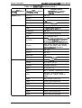
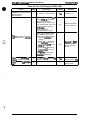
Table 1-12. SelecType Functions (Cont.)
Menu
(Chan M & M E N U
!
ESCP2 (Cont.)
FX
GL2
1-22
Available Options
(Chan ad by ~or ~ button)
(Set%y ENTER button)
(Chang~ t!~~EM button)
Auto CR
ON, OFF
Auto LF
ON, OFF
Zero Char
o, ($
Bit Image
Dark, Light, BarCode
Font
Courier, Prestige, Orator S
Pitch
10 CPI, 12 CPI, 15 CPI, Prop
Condensed
ON, OFF
T-Margin
0.40 to 1.50 Inch (step 0.05)
Text
1 to (Available) LINES
CG Table
Italic, PcUSA, PcMuitilin, PcPortugues,
PcCanFrenc, PcNordic, PcTurk2,
Pc.E.Europe, BpBRASCll, BpAbicomp
Country
USA, France, Germany, UK, Denmak,
Sweden, Italy, Spainl, Japan, Norway,
Denmsrk2, Spain2, LatinAmeric
Auto CR
ON, OFF
Auto LF
ON, OFF
Zero Char
o,@
Bit Image
Dark, Light, BarCode
GLMODE
LJ4GL2, GLlike
SCALE
OFF, AO, Al , A2, A3
ORIGIN
CORNER, CENTER
PEN
0, 1,2,3,4, 5,6
END
BUTT, SQUARE, TRIANGULAR, ROUND
JOIN
MITERED, MITEREDBEVELED,
TRIANGULAR, ROUND, BEVELED,
NONE
PENO
0.05 to 5.00 mm (step 0.05)
PEN1
0.05 to 5.00 mm (step 0.05)
PEN2
0.05 to 5.00 mm (step 0.05)
PEN3
0.05 to 5.00 mm (step 0.05)
PEN4
0.05 to 5.00 mm (step 0.05)
PEN5
0.05 to 5.00 mm (step 0.05)
PEN6
0.05 to 5.00 mm (step 0.05)
Rev. A
Ganerai ~ription
EPL6600 /ActionLaaar 16U0 Sarvica Manual
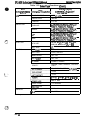
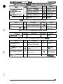
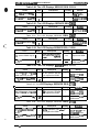
Table 1-12. SelecType Functions (ContJ
(Chan
Available Options
(Chan ad b ~or~ button)
(Sat%y EdTER button)
Menu
W MENu (chang~ $~EM button)
r
utton)
JOI3
EMULATION
PAGE PROTECT
OFF, LT, LGL, A4
RESOLUTION
300,600
TIMEOUT
5 to 300
PARALLEL
LJ4, FX, ESCP2, PS*, GL2, PMLJ4*,
PS&FX*, PS&ESCP2*, PS&G12*
SERIAL
LJ4, FX, ESCP2, PS*, GL2, PS&LJ4*,
PS&FX*, PS&ESCP2*, PS&GL2*
LJ4, FX, ESCP2, PS*, GL2, PS&LJ4*,
PS&FX*, PS&ESCP2*, PS&G12
;.
AUX*
LJ4, FX, ESCP2, PS*, GL2, PS&LJ4*,
PS&FX*, PS&ESCP2*, PS&GU2*
STD SIZE
A4, A5, B5, LT, HLT, LGL, GLT, GLG,
EXE, F4, MON, C1O, 01, C5, IB5
OPT SIZE*
LT, A4
STD TRAW
LOCK, UNLOCK
OPT TRAY*
LOCK, UNLOCK
SIZE IGNORE
OFF, ON
AUTO CONT
OFF, ON
STANDBY
DISABLE, ENABLE
DENSITY
MEDIUM, DARK, DARKEST, LIGHTEST,
LIGHT
n,
.“.
‘.-, .,
TRAY SIZE
CONFIG
ON, PARALLEL, SERIAL, (UT), (AUX)
o to 99
----
(-,: “
0 to 99
E***-F,
E****
F,
E-* F, p
F, E. F ,
5000 to 9000
PAGE COUNT
o to 99999999
SelecType INIT
PARALLEL
SPEED
I BI-D
FAST, LOW
t
I ON, OFF
* With option
Rev. A
1-23
EPL-5600/ActionLaser 1600 Service Manual
General Description
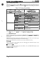
Table 1-12. SelecType Functions (Cont.)
I
I
Menu
(Chan M&MENIJ (Changd #~~EM button)
f
SERIAL
,
SERIAL TYPE
RS232C, RS422
WORD LENGTH
8,7
BAUD RATE
9600, 19200,38400,57600,300, 600,
1200,2400,4800
PARITY
NONE, EVEN, ODD
STOP BIT
1,2
DTR
ON, OFF
I XON/XOFF
TEST
Available Options
(Chan ad by ~or ~ button)
(Set%y ENTER button)
I ON, OFF
DSR
ON, OFF
STATUS SHEET
—
I LJ4FONTSAMPLE
1-
ESCP2 FONT SAMPLE
—
FX FONT SAMPLE
—
FACT SHEET
—
RITech TEST PAGE
—
I PS STATUS SHEET* I –
PS FONT SAMPLE*
—
PS FACT SHEET*
—
* With option
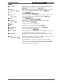
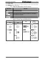
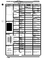
1.4.3 Service Mode
This printer has four service modes as follows:
■ Hexadecimal Dump Mode
■ Language Setting Mode
■ Factory Service Mode
■ EEPROM Format
1.4.3.1 Hexadecimal Dump Mode
The hexadecimal dump mode is a useful tool in trouble shooting data control problems. To enter
hexadecimal dump mode, turn on the printer while holding down the ON LINE button until
“HEX DUMP MODE” is displayed.
1.4.3.2 Language Setting Mode
The language setting mode allows the user to specify a language for panel displays and the status
sheet. To enter language setting mode, turn on the printer while holding down the MENU button
until “CONFIG LANGUAGE” is displayed. The options are changed by pressing the ~ and ~
buttons and are set by pressing the ENTER button. Available options areas follows:
ENGLISH, FRAN~AIS, DEUTCH, ITALIANO, Espatiol, SVENSKA, DANSK, NEDERL, SUOMI,
PORTUGUI%
1-24
Rev. A
General Desor@ion
EPL-66@lActionLaser 16iUl Servke A&mud
1.4.3.3 Factory Service Mode
The factory service mode is a useful tool fir service people. This mode is not available to users. To
enter factory semice mode, turn on the printer while holding down the ON LINE and CONTINUE
buttons until “PRODUCT MENU” is displayed. The factory service settings are shown in
Table 1-13.
Table 1-13. Factory Service Mode
Menu
(Chang~~~)MENU
PRODUCT
NAME
TCOUNT
I TCOUNTCLEAR
PCOUNT
PCOUNT CLEAR
I JCOUNT
<...
VERSION
Available Options
(Cha
by T or 4 button)
(Set
Y
yENTERbutton)
(Chanx #~~EM button)
I AL1600, EPL-5600
1
I (Note 1)
1
I (tOfWleft COUnterCl@
I (page countervaluedisplayed)
I
I (page countafclear)
1
[ (jamcountervalue displayed)
JCOUNT CLEAR
(jam counter clear)
CODE ROM
(diaplayed version)
FONT ROM
I (diaplayed version)
I
LL ROM
(Local Language ROM)*
(diaplayed version)
PS ROM (EPSONScript
Module ROM)*
(displayed version)
* With option
Note 1: This counter value is Ieftof toner weight (pgrams) in imagingcartridge.
1.4.3.4 EEPROM Format
,[
EEPROM format operations are required only when the Video Ccmtroller Board (C125 MAIN
board) or EEPROM is replaced and these operations are specified in the accompanying
documentation.
EEPROM format functions (printer mme, default paper size (A4 or letter), toner counter, page
counter, jam counter, and panel settings) are all stored in memory.
Defaults for the EEPROM format functions can be written to EEPROM as follows:
■
EPL-5600
Turn on the printer while holding down the ITEM, ?, and CONTINUE buttons until
“FORMAT=EPL5600” is displayed.
H ActionLaser 1(XXI
Turn on the printer while holding down the MENU, ALT, and FORM FEED buttons until
“FORMAT=AL1600” is displayed.
Rev. A
1-25
EPL-5600/ActionLaser 1600 Service MAnual
General Description
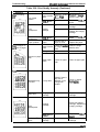
1.4.4 Display of Messages
This printer displays three types of messages on the LCD: status messages, error messages, and
power on messages.
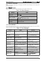
1.4.4.1 Ststus Messages
The LCD panel normally indicates the printer’s status and the software mode.
Table 1-14. Status Messages
status
Message
SELF TEST
RESET ALL
Internal self test
Warm txwt
RESET
Resetting
SelecType is changed while Form Feed light is on.
Press the RESET button to reset.
Warming up
RESET TO SAVE
WARMING UP
TONER LOW
Detect toner low
Power down mode
Normal condition
STANDBY
READY
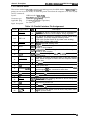
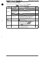
1.4.4.2 Error Messages
If any of the following errors occurs, it will be displayed on the LCD panel. The error must be
cleared immediately using the measures shown in the following table.
Table 1-15. Error Messages
Message
status
PAPER JAM
A paper jam has occurred.
FEED JAM
A paper jam has occurred in the
feed process.
PRINTER OPEN
Cover is open.
MANUAL FEED
Select manual feed.
PAPER OUT
No paper is left in either the
standard tray or the optional
cassette.
TONER OUT
PAPER SET
Measures
Open the cover and remove the
jammed paper. Then close the
cover.
Remove the jammed paper. Then
press the CONTINUE button.
Close the cover.
Insert paper and press ON LINE
button.
Load paper in paper tray or
optional cassette.
Over 25 pages have printed since
Replace the imaging cartridge.
a toner low condition was detected.
Load proper paper and press the
The paper in the selected tray is
CONTINUE button, or simply press
different from the paper size
the CONTINUE button.
selection.
PRINT OVERRUN
Engine speed faster than print
image processing.
Press the CONTINUE button.
MEM OVERFLOW
Data has filled the buffer.
Confirm and press the CONTINUE
button. And add optional SIMM.
ILLEGAL CART
INSERT CART
1-26
The inserted cartridge is not
Remove cartridge and press
CONTINUE button.
supported.
Cartridge was removed wh!le Form Reinstall
press
Feed light was on or the printer
CONTINUE button.
was on line.
cartridge and
Rev. A
General Dssctipmn
EPL-5600 /ActbnLasar 16(M SeWce Manual
Table 1-15. Emor Messages (Cont.)
I
I
Message
I
status
REMOVE CART
Cartridge was insetted while Form Fed
light was on or the printer was on line.
RAM ERROR
(Note)
Either the SIMM is damaged or it is not
supported.
EEPROM ERROR
EEPROM data error.
SERVICE REQ.
Xxxxx
Printer problem.
Note:
I
Msasuree
Remove cartridge and press
CONTINUE button.
Power off and then remove
SIMM.
I press the
CONTINUE
button.
Service required.
This printer displayed “RAM ERROR 1“ or “RAM ERROR 2“. If “RAM ERROR 1“ is
displayed, the problem is caused by the SIMM inserted in socket mnnector CN8. If
“RAM ERROR 2“ is displayed, the problem is caused by the SIMM inserted in socket
comector CN9.
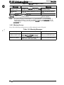
1.4.4.3 Warning Message
If any of the following warnings occurs, it will be displayed on the LCD panel.
.,
i
Table 1-16. Warning Messages
‘. ..-
Message
status
Measures
CHECK PAPER SIZE
The paper in the selected tray is
different ftom the mr)er size chosen
when SIZE IGNORE = OFF setting.
Press the CONTINUE button.
IMAGE OPTIMUM
Because of insufficient memory, the
printer uses a lower print quality.
Press the CONTINUE button.
Rev. A
1-27
EPL4600/ActionLaser 1600 Service Manual
General Descrbtion
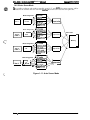
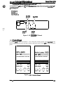
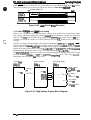
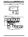
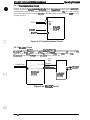
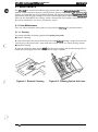
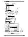
1.4.5 Printer Sharing
This section describes printer sharing. This printer has two methods of printer sharing, port fixed
mode and auto sense mode. These modes are selected by SelecType menu “AUTO SENSE”.
1.4.5.1 Port Fixed Mode
When the printer is in port fixed mode, only one interface port is active. Data from other ports is
ignored.
Mode Assignment
Parallel
User 1
: I
s
Mode Assignment
}“ ““ ““---
I
>
‘Y %%”:s’ript 1’ \
HP mode
ESC/P2 mode
Serial
User 2
.
FX mode
GL2 mode
EpsonScript
mode
Switched by
SelecType
I
I
Memory
Mode Assignment
ESC/P2 mode
.
User 3
LIT
Mode Assignment
FX mode
GL2 mode
EpsonScript
mode
HP mode
ESC/P2 mode
User 4
AUX
FX mode
GL2 mode
EpsonScript
mode
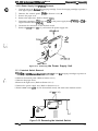
Figure 1-10. Port Fixed Mode
1-28
Rev. A
G@lerai IMacd@k?n
EPL-5600/ActionLaser 16tM Service Manuai
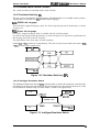
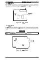
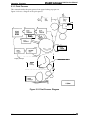
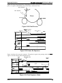
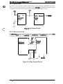
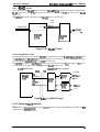
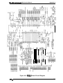
1.4.5.2 Auto Sense Mode
It is possible to allocate each mode to parallel, serial, L/T, and ALJX. ‘l’he entire memory will be
allocated to the channels that are used. The intert%ce that receives the data first will print first.
.
Mode Assignment
HP mode
ESCIP2 mode
4
FX mode
Parallel
User 1
GL2 mode
EpsonScript
mode
)
Mode Assignment
ESC/P2 mode
El-
Serial
User 2
‘---
Input buffer \
.
GL2 mode
EpsonScript
mode
,-.
(“
\ Auto Sense
FX mode
Memory
‘
.
Mode Assignment
D
Input buffer ‘
LIT
User 3
●
Mode Assignment
ESC/P2 mode
I
I I
.,, ”
AUA
FX mode
h\l
d
1
N
EpsonScript
Y mode
v
Figure 1-11. Auto Sense Mode
i:’
$,
Rev. A
1-29
EPL-5600/ActionLaser 1600 Service Manual
General Description
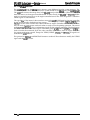
1.4.6 Emulation Mode Switch Function
This section describes the emulation mode switch function.
1.4.6.1 Emulation Switch by SPL
The two types of emulation switch functions described below are available on this printer.
Together they are referred to as SPL (Shared Printer Language).
EJL: EPSON Job Language
This is EPSON’s original language system. It is able to skip among various destinations, as shown
in Figure 1-12.
PJL: Printer Job Language
This is HP’s original language, which is available with the LaserJet 4 printer.
It is able to skip among various destinations, as shown in Figure 1-12. The precise specifications for
this language are based on the HP LaserJet 4.
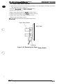
The figure below shows three types of mode switching.
Neither EJL nor PJL switches the mode directly. They first exit the current mode and return to EJL
or PJL. Then they enter another mode.
W4
EPSON GL2
Figure 1-12. Emulation Switch by SPL
1.4.6.2 Intelligent Emulation Switch
The Intelligent Emulation Switch (IES) automatically switches the emulation switch mode,
depending on the data sent from the host computer through one of the interface channels. It is able
to switch between EPSON Script and other modes as shown in the figure below.
ESCP2
LJ4
q&LJ4
< S & ESCP2
EPSON Script
FX
EPSON GL2
Figure 1-13. Intelligent Emulation Switch
1-30
Rev. A
Geneml lhscd@on
EFi-5600 /ActkmLaser 16(XI Sendc8 U%nual
1.4.7 Bi Resolution improvement Technology
The EPL-5600/ActionLaser 1600 printers have BiRiTech @i Resolution Improvement t Technology),
which is designed to improve print quality at 6MI dpi and 300 dpi. By this method, the dot map
data extracted from the image data is reassembled to impmve print data.
The main improvement of this technique is in eliminating “jaggies” in diagoml lines. It is most
effective when the dot map data fits the development characteristics of the printer mecbnism well.
his therefore nemssary to set appropriate values in SelecType.
“1
2
3
600
4
II
I
I
I
.
g
‘-. ,
1 inch
I
/
R
+’00(When 600 DPI printing)
Figure 1-14. Effect of BiRiTech
Note:
BiRITech is not as effective for printing a mesh pattern or gray scale. In such cases,
BiRITech must be set to OFF. (The default setting is MEDIUM.) Since the BiRITech effect
depends on the toner condition, it should be adjusted when the imaging cartridge is
replaced or after the imaging cartridge is used for a long time.
The following settings are available in SelecType Level for RITech: DARK, MEDIUM, LIGHT, OFF.
When the toner density of area A is almost the same as that of area B (as shown in the figure
below), the RITech setting is at its optimum setting. In other words, the optimum setting is
achieved when it is difficult to distinguish the shape of area A from that of B.
A
B
/
/
!’
Figure 1-15. RfTech Adjustment
Rev. A
1-31
General Description
EPL-561W/ActionLaser 1600 Service Mhnual
1.4.8 Optional Memory
If you have difficulty printing complex, graphics-intensive pages or if you regularly use
downloaded fonts, you may need to install the optional SIMM sets on this printer’s controller
board. The printer’s controller board comes with 2.0 MB of RAM installed.
By installing additional SIMMS, you can increase the printer’s memory to a total of 64 MB,
including the resident memory.
EPSON supplies several types of memory option (SIMM). Other SIMMS can be purchased from
other vendors. Be sure the SIMM meets the requirements listed below.
■ 72-pin type
■ Capacity is one of the following: 1,2,4,8,16,32 MB
■ Access speed is less than 70 ns.
■ With-in the following dimensional size
36 mm (Height) x 108 mm (Width) x 10 mm (Depth)
1-32
Rev. A
EPL+600/ActionLaser 1600 Servke Manual
GensralLhscdptbn
1.5 MAIN COMPONENTS
To simplify maintenance and repair, the main components of the EPL-5600/Actionbser 1600 have
been designed for easy removal and replacement. The main components are:
c1 C125 MAIN Board
Video controller circuit board
Q C82326X I/F (optional)
Optional LocalTalk module
c1 Control Panel
a PWB-A Board
Engine controller arcuit board
0 PWB-E Board
Power supply circuit board
ii PWB-F Board
High-voltage supply arcuit board
a Optical Unit
Printhead unit
L1 Fusing Unit
c1 Drive Unit
c1 Imaging Cartridge
c1 Housing
a Lower Paper Cassette Unit (optional)
o Face-up Output Tray (optional)
Face-up Output Tray
/
.FUSING UNIT
Panel
PWB-F Board
. . . ..
PRINTt+EAD UNIT
‘. .
Board
\
Cassette
C125 MAIN Board
Figure 1-16. Component layout
Rev. A
1-33
EPL-6600/ActionLaser 16(70 Service Manual
General Description
1.5.1 C125 MAIN Board
The C125 MAIN board is a video controller board. The primary functions of this board are
receiving print data from the host, generating the print image (video), and sending the print image
to the engine controller via the video interface. A 32-bit 17.6 MHz RISC CPU MB86930 (SPARKlite)
(location: IC1) is used, and the following memory chips and custom ICS are assigned to the 4 GB
memory space.
■ Memory chips
Code ROM: four 4M-bit EP-ROM (IC7, 8,15, 18) or two 8M-bit mask ROM (IC21, 22)
Font ROM: two 8M-bit mask ROM (M80A74: IC4, M80A75: IC5)
4M-bit DRAM (IC16, 17,19, 20)
16K-bit EEPROM (IC8)
■ Custom ICS
ASIC E05A91 (IC9)
ASIC E05A92 (IC25)
ASIC E05A93 (IC24)
■ Others
RS-232C interface driver/receiver ADM232 (IC28)
RS-422 interface driver/receiver MC34050 (IC6)
Reset IC M51953BFP (IC27)
8M ROM
(IC2])
8M ROM M80A75
(IC5)
16K
(IC22)
4
4
(1
ADM232
(IC28)
E05A93
(IC24)
Lo
Language
ROM
(option)
\
E05A92
(IC25)
(Icll)
\
<
1
/
/
I
!
\
/
4M DRAM (IC20, 17,19, 16)
E05A91
(IC9)
MB86930
(lCl)
Figure 1-17. C125 Main Board
There are two types of C125 MAIN boards used as after service parts. The following table shows
differences between them.
Table 1-17. Differences in Components for the C125 MAIN Board
ActionLaser 1S00
EPL-5600
Serial interface connector
Mini screw type connector
Inch screw type connector
ICI 1
IC socket
None
1+4
Rev. A
EPL4WM /Ac~ 16W Sorvko Manual
GenemIlhecdpuon
1.5.2 C8232M I/F Board (Optionai LocaiTaik Module)
The C8232f# I/F board has the LocalTalk interfam arcuit, which allows this printer to mnnect to
Apple” Maantosh” computers. l’he LocalTalk Module is available for a LocalTalk mmwctkm.
■ Main Chips
85C30 (IC3)
26T.530 (ICI)
26LS32 (1(2)
NJU7660 (IC4)
26LS31
(1:1)
r
v
f
NJU7660
(K%)
..* : +.:. ,
/
I
9
*
a
9
*
,,; ,
/
●
●
●
*
. . .
a. . . . .C ● - - - * - - -*
8
9
*
,
*--,
,
.,*
i
*,,
9,,
.-. ., .
\
● .
.:. :
*
*
,::
,- . . +. . . .
/
\
/
26LS32
(IC2)
I
(IC3)
Figure 1-18. C8232&k i/F Board
1.5.3 Controi Panei
control paneI includes a 20 column x 1 row LCD panel, which provides many functicms for the
printer (e.g., displaying error messages or printer operation status). There am two types of control
panels.
The
SUPER MICROART PRINTING
Figure 1-19,
Rev. A
Is
EPL-5600/ActionLaser 1600 Service Manual
General Descri~tion
1.5.4 PWB-A Board
This is the engine controller board. It consists ofanM37451M48-bit CPU (including a MASK ROM)
and a gate array. The board controls laser scanning (the polygon mirror drive motor), image
synchronization, laser beam pulse width, and power.
I
I
“,.lfl ~M37451 M4
Figure 1-20. PWB-A Board
1.5.5 PWB-E Board
The PWB-E is the power supply board, which consists of a switching regulator circuit. It converts
the AC line voltage into +24 V and +5 VDC voltages. There are two types of power supply board,
the 100/120 V type and 220/240 V type. The difference between the two circuits is only in the input
section.
Do not touch VRIE on PWB-E board. This volume is for factoy setting only.
F2
F1
VRIE
❑
Figure 1-21. PWB-E Board
1-36
Rev. A
EPL-56W /Ac#mLaser 16tM SeWlce Manual
Genrnlhwxiption
1.5.6 PWB-F Board
The PWB-F is the high-voltage supply circuit board. It converts the development bias, OPC drum
charge bias, and image transfer bias.
Do not touch VRIF and VR2F on ths PWB-F boani. These volunass am~ factory ssth”ng only.
❑
o
c1
,. . .. .
I
Ii31
VRIF
VR2F
❑
‘L. . . .
Figure 1-22. PWB-F Board
1.5.7 Optical Unit
The optical unit consists of the laser diode (sernkonductor laser), the mirror motor ( scanner motor)
which drives the polygon mirror for laser scanning and several mirmrs and lenses. The laser beam
generated by the laser diode is conducted to the OPC drum surface by way of the polygon mirror,
as well as several mirrors and lenses, to create a latent electro-photographic image on the drum.
Figure 1-23. Optical Unit
...
Rev. A
1-37
General Description
EPL4600/ActionLaser 16(W Service Manual
1.5.8 Fusing Unit
The fusing unit fixes the toner to the paper using heat and pressure. This unit has a heater lamp,
thermistor, and thermal fuse. There are two types of fusing units, the 120 V type and the 220/240 V
type. The only difference between them is the heater lamp.
1.5.9 Drive Unit
The drive unit consists of the main motor and a series of gears and clutches. It drives the paper
transport rollers, OPC drum, sleeve roller, fusing roller, and some other mechanisms.
~
Figure 1-25. Drive Unit
1.5.10 Imaging Cartridge
The core mechanisms of the printing process, such as chargin~ developing and cleanina are
integrated into this imaging cartridge.
Figure 1-26. Imaging Cartridge
1-38
Rev. A
EPL-661W/ActionLsser 16(X) Servioa Manual
General Description
1.5.11 Lower Paper Cassette
The optional lower paper cassette allows you to feed up to an additional 250 sheets of A4 or
letter-size paper into this printer.
Figure 1-27. Lower Paper Cassette
1.5.12 Face-Up Output Tray
The face-up output tray is an optional tray useful for feeding single sheets of paper types, such as
envelopes, transparencies, labels, or heavy paper. The face-up feeding method reduces curlin~ and
the tray catches the paper at the paper ejection area at the top back of the printer.
Figure 1-28. Face-Up Output Tray
Rev. A
1-39
Chapter2 Operating Principles
Table of Contents
2.1 ENGINE OPERATION
2“1
2.1.1 Print Process. . . . . . . . . . . . . . . . . . . . . . . . . . . . . . . . . . . . . . . . . . . . . . 2-2
2.1.1.1 Paper Feeding. . . . . . . . . . . . . . . . . . . . . . . . . . . . . . . . . . . . . . . 2-3
2.1.1.2 Drum Charge. . . . . . . . . . . . . . . . . . . . . . . . . . . . . . . . . . . . . . . . 2-4
2.1.1.3 Laser Exposure.. . . . . . . . . . . . . . . . . . . . . . . . . . . . . . . . . . . . . 2-5
2.1.1.4 Development. . . . . . . . . . . . . . . . . . . . . . . . . . . . . . . . . . . . . . . . 2-5
2.1.1.5 Drum Cleaning . . . . . . . . . . . . . . . . . . . . . . . . . . . . . . . . . . . . . . 2-5
2.1.1.6 Image Transfer.. . . . . . . . . . . . . . . . . . . . . . . . . . . . . . . . . . . . . 2-6
2.1.1.7 Fusing. . . . . . . . . . . . . . . . . . . . . . . . . . . . . . . . . . . . . . . . . . . . . 2-6
2.1.1.8 Paper Exit. . . . . . . . . . . . . . . . . . . . . . . . . . . . . . . . . . . . . . . . . . 2-6
2.1.2 Engine Control. . . . . . . . . . . . . . . . . . . . . . . . . . . . . . . . . . . . . . . . . . . . . 2-7
2.1.2.1 Main Motor Functions and Control . . . . . . . . . . . . . . . . . . . . . . . 2-8
2.1.2.2 Paper Take-Up Sensorand PaperExitSensor. . . . . . . . . . . . . 2-10
2.1.2.3 FuserControl . . . . . . . . . . . . . . . . . . . . . . . . . . . . . . . . . . . . . . 2-10
2.1.2.4 Scanner Mirror MotorControl . . . . . . . . . . . . . . . . . . . . . . . . . . 2-11
2.1.2.5 LaserDiode Drive. . . . . . . . . . . . . . . . . . . . . . . . . . . . . . . . . . . 2-12
2.1.2.6 BiasVoltagesand LaserDriveTiming . . . . . . . . . . . . . . . . . . . 2-13
2.1.2.7 Fan MotorControl. . . . . . . . . . . . . . . . . . . . . . . . . . . . . . . . . . . 2-15
2.1.2.8 Power Supply Circuit Function and Safety Protection, . . . . . . . 2-15
2.2 VIDEO CONTROLLER OPERATION
2-16
2.2.1 C125 MAIN Board Operation. . . . . . . . . . . . . . . . . . . . . . . . . . . . . . . . . 2-16
2.2.1.1 Reset Circuit-. . . . . . . . . . . . . . . . . . . . . . . . . . . . . . . . . . . . . . . 2-19
2.2.1.2 BusControlCircuit . . . . . . . . . . . . . . . . . . . . . . . . . . . . . . . . . . 2-19
2.2.1.3 Interrupt Control . . . . . . . . . . . . . . . . . . . . . . . . . . . . . . . . . . . . 2-20
2.2.1.4 DRAM Management . . . . . . . . . . . . . . . . . . . . . . . . . . . . . . . . . 2-20
2.2.1.5 Parallel Interface Circuit . . . . . . . . . . . . . . . . . . . . . . . . . . . . . . 2-21
2.2.1.6 RS-232CCircuit . . . . . . . . . . . . . . . . . . . . . . . . . . . . . . . . . . . . 2-21
2.2.1.7 RS-422 Circuit. ... , . . . . . . . . . . . . . . . . . . . . . . . . . . . . . . . . . 2-22
2.2.1.8 LocalTalk Circuit. . . . . . . . . . . . . . . . . . . . . . . . . . . . . . . . . . . . 2-22
2.2.1.9 Optional Type-B Interface. . . . . . . . . . . . . . . . . . . . . . . . . . . . . 2-22
2.2.1.10 Video Interface . . . . . . . . . . . . . . . . . . . . . . . . . . . . . . . . . . . . 2-23
List of Figures
Figure 2-1. Main Components. . . . . . . . . . . . . . . . . . . . . . . . . . . . . . . . . . . . . . 2-1
Figure2-2. Print Process Diagram . . . . . . . . . . . . . . . . . . . . . . . . . . . . . . . . . . 2-2
Figure2-3. PaperFeedingfrom the Multi-Purpose Tray. . . . . . . . . . . . . . . . . . 2-3
Figure2-4. PaperFeedingfrom the Lower PaperCassette . ..............2-4
Figure2-5. Drum Charge . . . . . . . . . . . . . . . . . . . . . . . . . . . . . . . . . . . . . . . . . 2-4
Figure2-6. LaserExposure. . . . . . . . . . . . . . . . . . . . . . . . . . . . . . . . . . . . . . . . 2-5
Figure2-7. Development . . . . . . . . . . . . . . . . . . . . . . . . . . . . . . . . . . . . . . . . ..2-5
Figure2-8. Image Transfer.. . . . . . . . . . . . . . . . . . . . . . . . . . . . . . . . . . . . . . . 2-6
Figure2-9. Fusing . . . . . . . . . . . . . . . . . . . . . . . . . . . . . . . . . . . . . . . . . . . . . . . 2-6
Figure2-10. Engine Controller Connecting Diagram . . . . . . . . . . . . . . . . . . . . . 2-7
Figure2-11. Gearand Roller Positions. . . . . . . . . . . . . . . . . . . . . . . . . . . . . . . 2-8
Figure2-12. P/C Drive Section . . . . . . . . . . . . . . . . . . . . . . . . . . . . . . . . . . . . . 2-8
Figure2-13. Developing Drive Section . . . . . . . . . . . . . . . . . . . . . . . . . . . . . . . 2-8
Figure2-14. Fusing Drive Section. . . . . . . . . . . . . . . . . . . . . . . . . . . . . . . . . . . 2-8
Figure2-15. Feeding Drive Section. . . . . . . . . . . . . . . . . . . . . . . . . . . . . . . . . . 2-8
Figure2-16. Feeding Drive Section (Option). . . . . . . . . . . . . . . . . . . . . . . . . . . 2-8
Figure2-17. Main MotorDriveCircuit . . . . . . . . . . . . . . . . . . . . . . . . . . . . . . . . 2-9
Figure2-18. Paper Take-Up Sensor and Paper Exit Sensor On/OffTiming. . 2-10
Figure2-19. Fuser Control Circuit. . . . . . . . . . . . . . . . . . . . . . . . . . . . . . . . . . 2-10
Figure2-20. Temperature forFuserControl Procedure . . . . . . . . . . . . . . . . . 2-11
Figure2-21. Scanner Motor Control Circuit . . . . . . . . . . . . . . . . . . . . . . . . . . . 2-11
Figure2-22. Scanner Motor Driving Start Timing . . . . . . . . . . . . . . . . . . . . . . 2-11
Figure2-23. Laser Diode Drive Circuit . . . . . . . . . . . . . . . . . . . . . . . . . . . . . . 2-12
Figure2-24. /L DATA Generation Circuit . . . . . . . . . . . . . . . . . . . . . . . . . . . . . 2-12
Figure2-25. Laser Emission PowerAdjustment Timing . . . . . . . . . . . . . . . . . 2-12
Figure2-26. Laser Diode Error Detection . . . . . . . . . . . . . . . . . . . . . . . . . . . . 2-13
Figure2-27. High-Voltage Supply Block Diagram . . . . . . . . . . . . . . . . . . . . . . 2-13
Figure2-28. Print Process. . . . . . . . . . . . . . . . . . . . ...........;.. . . . . . . 2-14
Figure2-29. PowerOnSequence. . . . . . . . . . . . . . . . . . . . . . . . . . . . . . . . . . 2-14
Figure 2-30. Print Sequence (Start). . . . . . . . . . . . . . . . . . . . . . . . . . . . .....2-14
Figure2-31. Print Sequence (End) . . . . . . . . . . . . . . . . . . . . . . . . . . . . . . . . . 2-15
Figure2-32. Fan Motor Speed Control Timing . . . . . . . . . . . . . . . . . . . . . . . . 2-15
Figure2-33. Fan Motor Malfunction Search Timing . . . . . . . . . . . . . . . . . . . . 2-15
Figure2-34. Power Supply Circuit Block Diagram. . . . . . . . . . . . . . . . . . . . . . 2-15
Figure2-35. Video Controller Section . . . . . . . . . . . . . . . . . . . . . . . . . . . . . . . 2-16
Figure2-36. C125MAlN Board Block Diagram. . . . . . . . . . . . . . . . . . . . . . . . 2-16
Figure2-37. Data Flow Diagram . . . . . . . . . . . . . . . . . . . . . . . . . . . . . . . . . . . 2-18
Figure2-38. Reset Circuit . . . . . . . . . . . . . . . . . . . . . . . . . . . . . . . . . . . . . . . . 2-19
Figure2-39. BusControl Circuit . . . . . . . . . . . . . . . . . . . . . . . . . . . . . . . . . . . 2-19
Figure2-40. DRAM Management . . . . . . . . . . . . . . . . . . . . . . . . . . . . . . . . . . 2-20
Figure2-41. Parallel Interface Circuit . . . . . . . . . . . . . . . . . . . . . . . . . . . . . . . 2-21
Figure2-42. RS-232CCircuit . . . . . . . . . . . . . . . . . . . . . . . . . . . . . . . . . . . . . 2-21
Figure2-43. RS-422Circuit. . . . . . . . . . . . . . . . . . . . . . . . . . . . . . . . . . . . . . . 2-22
Figure2-44. LocalTalkCircuit. . . . . . . . . . . . . . . . . . . . . . . . . . . . . . . . . . . . . 2-22
List of Tables
Table2-1. Gearsand Rollers . . . . . . . . . . . . . . . . . . . . . . . . . . . . . . . . . . . . . . 2-9
Table2-2. Functions ofC125MAlN Board Main Elements. . . . . . . . . . . . . . . 2-17
EPL-6600 /&#onLaser 161W S4wvJce Manunl
OpWathg Princlpbs
2.1 ENGINE OPERATION
This section describes the functions and operating pMciples of the EPL-56W, ActimLaser 1600
engine.
Figure 2-1 shows the locations and names of the main engine mmponents.
6
12345
7
9
8
10
11
12
13
14
15
16
18
19
20
21
29
1.
2.
3.
4.
5.
6.
7.
8.
9.
10.
11.
12.
13.
14.
15.
28
Paper tray
Paper guide
Optical unit
Imaging cartridge
Upper lock release lever
Roller cover
Thermistor (TH1)
Face-down exit roller
Upper fusing roller
Heater lamp (Hi)
Face-up/face-down switching guide
Face-up tray (option)
Face-up exit roller
Fusing separator
Paper exit sensor (PC3)
27
26
16.
17.
18.
19.
20.
21.
22.
23.
24.
25.
26.
27.
28.
29.
25
24
23
22
Lower fusing roller
Toner empty sensor
cooling fan
Image transfer roller
Main motor (W)
Lower paper ca.wtte (option)
Paper taleup S4msor (PC2)
Transport roller
Transport roller (for option)
Paper take-up roller
Paper take-up roller (for optian)
Paper cassette (for option)
Paper empty sensor (PC4) (for option)
Paper empty sensor (pCl)
Figure 2-1. Main Components
. . .,.,
,:
Y,
‘.. ...
-’
Rev. A
2-1
EPL-5600/ActionLaser 1600 Service Manual
Operating Principles
2.1.1 Print Process
This section describes the print process from paper feeding to paper exit.
Figure 2-2 shows a diagram of the print process.
i—-—- —-
— --
Fusing
6.
7.
Toner
::;
Q!Elm-’,
6“
2.
Brush
Charging
D.
/’
3~
\
i
w%
m.!”;,
‘L - - .
—-—-—.-
./
-/”
Imaging Cartridge
-—. —- —. —.#l’–
1.
Paper
Feeding
1
—-—.—-—.—-—-—-—-—-
1.
Figure 2-2. Print Process Diagram
2-2
Rev. A
EPL-6600 /ActionLaser 161W Service Menual
Opwatig Princ@ee
2.1.1.1 Paper Feeding
There are two methods of feeding the paper into the printer. One is by using the multi-purpose
tray (standard tray), and the other is by using the optional 25kheet lower paper cassette.
Paper~ut conditions are detected by the paper empty sensor, located above the paper tray or the
cassette. While paper is in the tray or cassette, the detection lever for the paper empty sensor is
lifted. When the paper supply runs out, the detection lever is lowered, causing the shutter to
interrupt light from the LED to the photo-transistor. This causes the signal to go HIGH, informing
the engine driver that the paper tray or the cassette is empty.
When the paper take-up solenoid is actuated, the paper take-up roller rotates and feeds the first
page. The paper take-up roller stops after one rotation. Unlike the EPL-7@l(3/71MI/75M and
EPL-8000/8100, which have a synchronizing roller, the EPL-5600/ActionLaser 1600 has no
synchronizing roller installed. The timing to align the leading edge of the page with the image is
detected by the paper take-up sensor.
When the page is on top of the paper take-up sensor, the detection lever is lowered, allowing light
from the LED to reach the photo-transistor. This causes the signal to go HIGH, informing the
engine driver that paper has been detected.
....
,!
The paper exit sensor is located beyond the fusing roller in the paper path. When paper passes the
paper exit sensor, the detection lever is lowered, allowing light from the LED to reach the
photo-transistor. This causes the signal to go HIGH, informing the engine driver that paper has
been delivered.
Multi-Purpose Tmy (Standanl Troy)
The paper guide can be moved to fit against the sides of various sizes of paper, allowing the paper
to be fed.
Although the paper take-up roller stops after one rotation, the transport rollers continue to fed the
first page, because these rollers are independent of the paper tak~up roller. At this time, the
depression cam attached to the paper takeup roller depresses the paper lift-up plate to prevent the
feeding of a second sheet.
Lower Fusing Roller-
Figure 2-3. Paper Feeding from the Multi-Purpose Tray
Rev. A
2-3
Operating Principles
EPL-5600/ActionLaser 1600 Service hfhual
Lower Paper Cassette
A maximum of 250 sheets can be loaded in the 250-sheet lower paper cassette (option). The
cassette must be capable of handling the paper size, however. (The lower paper cassette unit can
hold letter or A4 paper.)
The driving force for paper feeding and transport is from the transmission gear. All electrical
controls are performed on the printer side through the coupling comector.
Ca
Paper
te
Figure 2-4. Paper Feeding from the Lower Paper Cassette
2.1.1.2 Drum Charge
Drum charge is the process of charging the PC drum with static electricity before Iaser exposure.
This printer uses a brush charge method, rather than the corona charge method, to charge the
drum. In the brush charge method, there is no generation of ozone as a result of corom discharge.
This method also allows the drum to be charged at a low voltage, because a direct electric load is
applied to the PC drum.
I
Charged surface:
approx. -750V
Imaging Cartridge
I
#+-
-1.2KV
A*
approx. &
-1.2KV
-
GND B
a
T
-300V c
to
PC Drum
-375V
A: Drum Charge Bias B: Drum Ground
C: Developing Bias
D: Doctor Blade Bias
Figure 2-5. Drum Charge
2-4
Rev. A
Opwating Rincfpha
EFL4i6(MlActionbaar 16W Sarvlca h4hnua/
2.1.1.3 Laser Exposure
Laser exposure is the process of creating an invisible static electric image on the PC drum with
laser beams emitted from the optid unit. The mirror motor (scanner motor) rotates the six+ided
mirror counterclockwise to produce a laser light scan. (One side of the mirror produces one scan.)
The SOS (start of scan) sensor detects the laser rays fmm the fOS mirror and outputs the SOS
signals to make the starting position of each line of the image uniform.
Print Head Unit
Laser ernissiorl
Sos
PcDrurrl
ID
Approx.
-50V
L Potygon Motor
Invisible ataticeiactricity image
Figure 2-6. Laser Exposure
2.1.1.4 Development
Development is the process of creating a toner image on the PC drum bv amdvirvz toner to the
invisible static electric image. l’he do&or blade spre~ds a thin, even mat if m“~e~ ov& the flexible
sleeve. When the toner ~asses between the d&tor blade &d the flexible sleeve, it becon&
negatively charged. The flexible sleeve transports toner to the surface of the PC drum and controls
the development with the developing bias voltage.
No positively charged toner is transported to the PC drum, and the doctor blade is negatively
charged to prevent the printout from having a foggy background.
r
Resin Sleeve
0
Toner
()
~-m
- - -. - - -
1= I@prox.
pclv
I
,.
II
tv
II
+
PC Drum
Sleeve Roller
Figure 2-7. Development
2.1.1.5 Drum Cleaning
After the image is transferred onto paper, any re ~g toner on the PC drum is scraped off by
the cleaning blade and collected in the used toner bottie.
Rev. A
24
EPL-561W/ActionLaser 1600 Service Manual
Operating Principles
2.1.1.6 Image Transfer
Image transfer is the process of transferring the toner image created on the PC drum during the
developing process to the paper. This printer uses the roller image transfer method, instead of
corona image transfer, as the image transfer process. In roller image transfer, there is no generation
of ozone as there is with corona discharge. Also, there is no blurring caused by motion in the
image transfer, because the image transfer roller is maintained for the pressure bonding of the
paper with the PC drum.
A reverse bias voltage is applied so that the positive toner is not transferred onto the image transfer
roller. (The drum charge bias voltage is used.)
xc
PC Drum
+
R-b*
PC Drum
r
Image Transfer Roller
r
v
@
3
P
~ Image Transfer Roller
Sequential Bias
Approx. 3.2KV
‘?
Reverse Bias
Approx. -0.8KV =
J
Figure 2-8. Image Transfer
2.1.1.7 Fusing
Fusing is the process of fixing the toner image transferred during the image transfer process onto
the paper. This printer uses the heating roller method for fusing. The heating roller method fixes
the toner image with an upper fusing roller that is heated by the heater lamp.
After power is turned on, the heater lamp lights up until the temperature of the upper fusing roller
reaches 165° C (329” F). After warm-up, the mechanical control board controls the ON/OFF
operation of the heater lamp, based on the THl signals from the thermistor.
Upper Fusing
Roller
Thermal Fuse
TH1 Signals
Thermistor \
Lower Fusing
Roller
Heater Lamp
+
Paper Guide
~
Mechanical
Control
Board
Low Voltage
Power Supply Board
Figure 2-9. Fusing
2.1.1.8 Paper Exit
The paper on which the toner image has been fused is fed to the face-down tray or the face-up tray.
2-6
Rev. A
Opuating Prhc@laa
EPL-5600/ActlonLaaer 161M Sarvka Manual
2.1.2 Engine Controi
This section describes a@ne control, the power supply board, and the high-voltage supply board.
The engine is controlled by the engine controller board (PWEA board). Figure 2-10 shows an
engine ‘mntroller connecting diagram.
PWB-D
LD
Sos
Engine
:~;;~ller
,
Mirror
Scanner
Motor
--?.
J“ . . . . . .
.,<.~...,r
PWB-A
—
Charge Brush
zEl-
3
r
1
Video
:g;;~ller
C125
MAIN
Lower
Paper
Cassette
— Pa~er Take UD Solenoid SL1
~Paper Exit Sensor PS3
r
i
‘—’ Paper Empty Sensor PE1
I
Power SW
Paper Empty
Sensor
I
1
AC Power Input
Power
supply
Board
PWB-E
Cassette
Detecting
s “w
,. ,. > .,
. .
Paper Take Up
Solenoid SL2
PWB-G
Toner Empty
Sensor
I
Figure 2-10. Engine Controller Connecting Diagram
. *, I
., . .y.
Rev. A
2-7
EPL-56tW/ActionLaser 1600 Service Mimual
Operating Principles
2.1.2.1 Main Motor Functions and Control
Power from the main motor (Ml) drive is used for the P/C (photo conductor) drive, the developing
drive, the fusing drive, the standard paper slot feeding drive, and the lower paper cassette (option)
feeding drive. Figures 2-11 through 2-16 show the positions of the gears and rollers.
17 16 25
uAt3’1’
nr
-#I
Sleeve Roller
I
~ ~lrnage Transfer Roller
..— —- .
w
2
1
● 23 ● 22 ● 24
“26
Fig. 2-:~&~~~ Drive
Fi .2-11. Gear and
1?oiler Positions
Fig. 2-13. Developing
Drive Section
ri
Face Up Exit Roller
“26
‘i
Transport Roller
Transport
Roller
F&
● 27
● 24
● 22
● 21
● 23
/
)
%
L
18
Upper Fusing Roller
Revolution
36.40 ~m
process Speed
38.12 (m~s)
.d—-.
J’
1
Fig. 2-l~e~;~i#g Drive
2-s
/ 20
● 21
Paper Take-Up
Roller
14
11
.—.
7
Roller
2
4-
‘
-
d
.— -
. . . . .
1
Fig. 2-15A~~t;d#g Drive Fig. 2-16. Feeding Drive
Section (Option)
Rev. A
2
Opadng Iwdpbs
EIUWIM /llcfionLaser 161X? 6orvico R&mud
Table 2-1. Geara and Rollera
No. of Gear
Teeth
No.
No.
Roller Name
Noto&ear
Roller Name
1
18
2
2WW126
3
4
29
5
43
P/C Drum
19
6
7
30
47
P/C Dtum
20
21*
8
29/41
22*
24/32
1424
18
9
26
10
23
23*
24*
18
18
11
1 6/40
25*
16
12
46/69
26”
16
Paper TakWp Roller
13
23
27
28
Tranapd Roller
14
16t75
28
14
Image Tranafer Roller
●
Main Motor (Ml)
14/32
Sleeve Roller
Paper Take-Up Roller
Tranaport Roller
15
16
36
w
Upper Fuaing Roller
17
18
15
FacWMm Exit Roller
39148
15
Face-Up Exit Roller
Option (lower paper cassette)
Figure 2-17 shows the main motor drive circuit. The main motor (Ml) is a four-phase stepping
motor. This motor is controlled by the CPU (ICIA) on the engine controller board (PWB-A). l%e
power supply board (WVB-E) has a stepping motor driver IC. This IC drives the main motor (Ml)
with a constant current. The main motor (Ml) is stopped when the CPU (ICIA) on the en@ne
controller board (PWB-A) outputs TdA and TdB”signa~. ”
Power Supply
Board
PWB-E
Engine Controller
Board
PWB-A
CN8A
A
B
TdA
TdB
4
3
2
8
9
Ic
1
11
4
Main Motor Ml
;
3
4
5
6
Figure 2-17. Main Motor Drive Circuit
Rev. A
2-9
EPL-5600/ActionLaser 1600 Service Manual
Operating Principles
2.1.2.2 Paper Take-Up Sensor and Paper Exit Sensor
The paper take-up sensor has three functions:
1. To detect the top edge of paper. The engine starts printing when the detection signal
is received.
2. To detect paper size. The printer detects the time it takes for paper to pass the paper
take-up sensor during paper feeding. If this time is lon& longer paper is feeding;
if the time is short, shorter paper is feeding.
3. To detect paper jams and feed jams.
If the paper take-up sensor does not turn on for paper feeding, the printer detects a feed jam. A
feed jam is a paper jam that occurs in the feed process.
If any of the following conditions is detected, the printer detects a paper jam. A paper jam is a jam
that occurs in the printing process area.
●
●
The paper take-up sensor (PC2) or the paper exit sensor (PC3) is on at power on or when the
upper case is closed.
The paper take-up sensor (PC2) or the paper exit sensor (PC3) is not turned on/off within the
specified time. (Refer to the following tirningchart.)
Take Up Solenoid ON
[sec.]
10.53
PC2(CN7A-2)
$=q
$==+
PC3(CN6A-6)
N
Figure 2-18. Paper Take-U Sensor and Paper Exit Sensor
On/8ff Timing
2.1.2.3 Fuser Control
The fuser is heated bv the heater lamp, which is powered by AC voltage. When the power supply
board receives a FUSER LAMP signal from the engine controller board (PWB-A), the power supply
board (PWB-E) supplies the AC voltage to the heater lamp. This AC voltage is cut by the interlock
switch when the case is open.
The fuser temperature is detected by the thermistor. Based on the THl signals from the thermistor,
the entine co~troller board (PWB--A) controls the fising temperature (~65° C, 329° F) using the
FUSER LAMP signaL
Engine Controller
Board
(PWB-A)
CN1lA
THERMISTOR
+5V
CN8A
FUSER LAMP
1
Thermistor
Power Supply
CN4E
HEAT-L
‘
n
Heater
Lamp
11
HEAT-N
,
:. . . . . . . . . . . . . . . . . . . . . . . . . . . . . . . .
Figure 2-19. Fuser Control Circuit
2-1o
Rev. A
Optwathtg Principb8
EPL-56f30/ActionLaaar 16tM Sarvlca Manual
The following fi~re shows the fuser temperature mmtrol procedure.
Figure 2-20. Temperature for Fuser Control Procedure
If the following renditions are detected, the printer indicates a fuser error (the LCD displays
SERVICE REQ. EOO03).
. The thermistor temperature dces not reach55° C (131° F) within 15 secmnds.
. The warm-up period doesnotend within 120 seconds.
● The thermistor temperature drops to 130° C (266° F).
● The thermistor temperature exceeds 200° C (392° F).
The thermo fuse (TF1) cuts power if the temperature of the fusing section rises to an abnormally
high level (over 200° C, 392° F).
2.1.2.4 Scanner Mirror Motor Control
Figure 2-21 is the scanner mirror motor (M2) control circuit. The scanner mirror motor is driven
while the scanner motor receives the SCANNER MIRROR MOTOR (M.20N) signaL
En9ine Chmller Board
PWBA)
Scamar Mobr
M2
CN5A
5
+24V 4
3
2
1
m
Figure 2-21. Scanner Motor Control Circuit
Figure 2-22 shows the scanner mirror motor driving timing chart. The scanner mirror motor
rotates 0.15 seconds after the main motor (Ml) turns on. If the MIRROR MOTOR L(M2:LOCK) signal is not turned on within 3 sectmds after the scanner mirror motor turns on, the
printer indicates a scanner mirror motor malfunction.
w Main Motor On
M2:ON
(CN5A-3)
M2:LOCK
(CN5A-2)
mc.1
.
.
~
~
3.0
K
4
Figure 2-22. Scanner Motor Driving Start Timing
Rev. A
2-11
EPL-6690/ActionLaser 1600 Service Mhnual
Operating Principles
2.1.2.5 laser Diode Drive
Figure 2-23 shows the laser diode drive circuit. Laser diode emission is controlled by three signals
(L DATA, DA1, and DA2) from the engine controller board (PWB-A).
Laser Diode
—
S SCAN
co
DA2
DA1
LD
Sos
(PWB-D)
\ SOS Mirror
-
b
L DATA
J
SOS sensor
Engine Controller
Board (PWB-A)
Figure 2-23. Laser Diode Drive Circuit
The L DATA signal is the laser ON/OFF signal. When it is LOW, the laser emits, and when it is
HIGH, the laser stops emitting. L DATA is the combination of the two signals in the figure below.
If the VIDEO or the FORCED LASER DIODE ON signal is activated (LOW), the L DATA signal
will be active. The VIDEO signal is an image signal sent from the video controller board (C125
MAIN board). The FORCED LASER DIODE ON signal is a laser emission signal to apply the laser
beam to the SOS sensor.
Forced Laser Diode ON
?
.~”LDATA
from the Video
Controller Board
(C125 MAIN)
Figure 2-24. /L DATA Generation Circuit
The laser diode is forcibly activated between 0.2 seconds and 0.1 seconds after the scanner mirror
motor (M2) turns ON. At this time, laser emission power is adjusted. LDVR1 and LDVR2 are the
laser emission power adjust signals; they are analog signals. LDVR1 is a tunin~ and LDVR2 is a
fine tuning.
[Sec.]
~ Scanner Motor On
LDATA
(CN5A-7)
4
LDVR1
(CN5A-9)
LDVR2
(CN5A-1O)
LDLVL
(CN5A-11)
0.2
: :;
E
.,
I
::
., -1
1
: : :
: : :
:
:
Figure 2-25. Laser Emission Power Adjustment Timing
2-12
Rev. A
EPL-56W /Actkmbsef 16(M Se#Vke Mantd
Opefating Fhc@&@s
If the SCAN signal is not detected, the printer indicates a laser diode malfunction. If the scanner
mirror motor (M2) does not rotate, the printer also indicates a laser diode ~“on.
~ Scanner Motor On
LDATA
0.2
4
(CN5A-7)
rsac.1
*
SSCAN
(CN5A-12)
Figure 2-26. Laaer Diode Emor Detection
2.1.2.6 Biaa Voltagea and Laaer Drive liming
,>
P
\..
Figure 2-27 is a diagram of the drum charge bias voltage, image transfer bias voltage, doctor blade
bias voltage, and the developing bias voltage mntrol circuit. These bias voltages are generated
from the +24 VDC from the high-voltage supply board (PWB-F). If the printer detects a ~ open
condition, the interlock switch is set to OFF, which cuts the +24 VDC, which, in turn, cuts the bias
voltages.
These bias voltages are controlled by the engine controller board (PWB-A). The CHM3N (I-W-T’)
signal is the image transt%r (roller) bias voltage control. While this signal is LOW, the image
transfer roller is charged to 3.2K VDC by the high-voltage supply circuit. And while this signal is
HIGH, the image transfer roller is charged to418KVDC. The CHl:ON (HV</T.R)si@ con~
thedrumcharge. While this signal is LOW, the PCdrumischarged to-1.2KVDC.
The DB:CNT (HV-B.VR) signal is an analog signal for developing bias voltage control. This signal
controls the bias voltage l;vel (–300V to ~75K VDC) using ~og data. ‘The image densi~ is
controlled by the developing bi~ voltage level.
Power Suppty
Board
(PWB-PU)
Engine Controller
Board
(PWB-A)
High Voltage Supply
Board
(PWB-F)
●
✎✎✎✎✎✎✎✎✎
interlock
+24 VDC
+24 WC
>~ . . . . . . . . . . . . . . . . . . .
DB:CNT
CH2:ON
CH1:ON
●
●
☞
✚
✌✎✎ ✎
☞
✎✎✎✎✎✎✎✎✎✎✎✎✎✎✎✎✎✎✎✎✎✎✎
Image Transfer
Bias (CH2)
3.2K or -0.8 K VDC
Developing
Bias
-300 to -374 WC
P ..................
● .......................
:.. . + Drum Charge
-1.2 K VDC
. . . . + Doctor Blade Bias
,
-800 VDc
Figure 2-27. High-Voltage Supply Block Diagram
Rev. A
2-13
EPL-5600/ActionLaser 16(U3 Service Manual
Operating Principles
Figure 2-28 shows the print process, and Figure 2-29 shows the power on sequence. During the
power on sequence (initialization), the printer detects mechanical errors.
Brush Charging
Laser Exposure
Development
Figure 2-28. Print Process
Power On
Fuser Temperature
130” C (266” F)
165” C (.329” F)
Mirror Motor
(M2)
Main Motor
(Ml)
Drum Charge
(CH1)
Laser
Exposure (LD)
Development
(DB)
Image
Transfer (CH1)
Figure 2-29. Power On Sequence
Figure 2-30 shows the start print sequence. The printer’s engine starts printing when the PRINT
signal is received from the video controller board.
Print
Drum
Charge (CH1)
Laser
Exposure (LD)
Main Motor On
0.5
j 025
Development
(DB)
Image
Transfer (CHI)
: 0.62 ~
Figure 2-30. Print Sequence (Start)
2-14
Rev. A
Opwating Prindplaa
EPL-56W IActionLaaaw 161M Sarvica Manual
Figure 2-31 is the end of the print sequence. The printer stops the main motor (Ml) from rotating
when the paper exit sensor turns off after 2.53 seconds.
Main Motor Off
[sec.] y
Paper Exit Senaor Off
1.27
Drum
Charge (CH1)
.8
1.26
b
Laser
Expoeure (LO)
Development
(DB]
!t%%er (CH1 )
Figure 2-31. Print Sequence (End)
2.1.2.7 Fan Motor Control
:...
\
..
The fan motor (M3) rotates at all times after initialization of the engine has been completed. The fan
motor rotates faster during printing. When printing ends, the fan motor slows down after 15
seconds.
[sec.]
Fan Motor
(CN7A-9)
Figure 2-32. Fan Motor Speed Control Timing
If the voltage of pin IC1A44 on the engine controller board (PWB-A) does not exceed 150mV for
1 second, the printer indicates a fan motor malfunction.
powerorl
[eac.]
1.0
FAM M.
~
(CN7A-9)
Figure 2-33. Fan Motor Malfunction Search Timing
2.1.2.8 Power Suppty Circuit Function and Safety Protection
The printer’s power supply board (PWB-E) supplies the +5 VDC and +24 WC. The +24 VDC is
used as the bias voltage supply, main motor (Ml) drive, scanner mirror motor (M2) drive, fan
motor (M3) drive, and solenoid drive. For safety protection, the +24 VDC line is cut when the
interlock switch (case open switch) is off.
Interlock
Sw
1- +24 VW
AC IN
Power Supply Board
(lW/B-E)
+ +5 VDC
● SG
* FG
Figure 2-34. Power Supply Circuit Block Diagram
Rev. A
2-15
EPL-5600/ActionLaser 1600 Service Manual
Operating Principles
2.2 VIDEO CONTROLLER OPERATION
The video controller section generates the video signals for the received data. The video controller
section is separate in the C125 MAIN board and the control panel. The control panel is comected
to the engine controller board (PWB-A), but is controlled by the C125 MAIN board, which sends
the signals for the control panel through the engine controller board.
Video Controller Section
,-------- ---------- . . . . . . . . . . . . . . . . . . . . . . . . .,
0
,
0
,
,
,,
,.
●
●
.
0
✚
0
✌
✌
.
0
0
,
,
✌
C125 MAIN Board
●
✎
●
0
✎
.
✌
✌
,
0
0
,
,
,
.
,
● ✎ ✎ ✎ ✎ ✎ ✎ ✎ ✎ ✎ ✎ ✎ ✎ ✎ ✎ ✍ ✎ ✎ ✎ ✎ ✎ ✎ ✍✍✍✍✍ 4---o
,
.
,
*
,
.
Cln
Engine
Controller
Boerd
:
S
(PWB-A)
Control
Panel
~
., . . . . . . . . .
,
S
:.
,,
,,
..4
Figure 2-35. Video Controller Section
2.2.1 C125 MAIN Board Operation
Figure 2-36 shows a block diagram of the C125 MAIN board. The C125 MAIN board contains the
video controller, which consists of a MB86930 (SPARKlite, 17.6 MHz, 32-bit bus) RISC CPU, the
standard cells developed for this printer, DRAM, ROM, and a 16K-bit EEPROM.
ROM 16M
(IC21, 22 or
IC7, 8, 18, 15)
ROM 16M
(IC21, 22)
CPU
MB86930
(lCl)
u
EEPROM
(ICE)
Font
Cartridge
JI
!1
T
[
i
I
I
1
T[
E05A92
(IC25)
E05A91
(1C 9)
ADDRESS
DATA
CONTROL
E05A93
(IC24)
1/0 DATA
ADDRESS
[
DRAMs
(IC 16,17,
19, 20) and
SIMMS
(cNE, 9)
I
1
ROME
(Icll)
I
v
v
Video l/F ;grallel
4
ADM232
(IC28)
:::)’’050
J
RS-232C
J
RS-422
lpe
B
b’;dule
4
4
t3~ecific LocalTalk
Figure 2-36. C125 MAIN Board Block Diagram
2-16
Rev. A
O$uanng Ptinc@se
EPL-561W/ActbnL8ser 16tM SetVke Menud
Table 2-2 lists the functions of the C125 MAIN board main elements.
Table 2-2. Functions of C125 MAIN Board Main Elements
Element
MB86930 RISC
CPU
ICI
E05A91 ASIC
IC9
E05A93 ASIC
IC24
This ASIC contains the following fundions:
. Video interface
. Bi-Parallel interface
● RS-232C interface
. RS-422 interface
● LocaiTaik module control
● Type-B interface card control
. Control panel control
Two 8M ROMs or
four 4M ROMs
IC21 ,22 or
IC7,8,18,15
These ROMs are code ROM.
Two 8M ROMs
10$,5
8M ROM
Icll
These ROMs are font ROM.
This ROM is local Iangw,ge ROM (fonts) option (except in
ActionLaser 1800).
EEPROM
Iclo
This EEPROM stores the folbwing:
. Model type
. Printed page counter value
. Toner life counter value
. Jam counter value
. SelecType setting
These DRAMs are used as the working area of the CPU:
input buffer, image buffer, etc.
ADM232
IC16,17,19,
20
IC28
MC34050
IC8
This IC changes the RS-422 signal level.
DRAM
.,’.
The CPU, whch operates at 17.6 MHz, manages the video
controller operation.
This ASIC contains the following functions:
. Address decoding
. DRAM management (refresh control,
RAS/CAS control)
IC25
‘w&”
...
~:,
,., . . .. .
Function
This ASIC contains the folbwing functions:
● Video signal processing
. BiRITech
● EMGTech
E05A92 ASIC
,.,--.%,
;.,
~. . . . . . .
Location
This IC changes the RS-232C signal level.
-.
,, ,,
,.,
Rev. A
2-17
EPL-6600/ActionLaser 1600 6ervice Manual
Operating Principles
Print data and commands transmitted from the host computer via parallel, serial, or optional
interfaces are read using the interrupt process of the CPU and stored in the DIUM input buffer.
Data and commands in the input buffer are processed by the CPU, which then stores the printing
bitmap data (image data) in the V (video) -RAM (image buffer) in the DRAM. The size of the
V-RAM depends on the available DRAM size. A “PRINT OVERRUN” occurs when the V-RAM is
so small that the CPU cannot process data faster than it is transmitted to the engine controller
board. If such an error occurs, the user can increase the V-RAM by using SelecType setting “PAGE
PROTECT”.
The E05A91 transmits image data stored in the V-RAM to E05A92. The E05A92 changes image the
data format from 32 bits parallel data to serial data, and stores it in the internal temporary buffer.
The temporary buffer has a capacity equivalent to several lines. This is controlled by the E05A92,
which synchronizes and transmits the tempora~ buffer’s data to the engine controller board. The
E05A92 then manipulates the printer data according to the BiRITech and EMGTech settings.
E05A91
(IC9)
CPU
MB86930
(ICI)
E05A93
(IC24)
—
— Host Computer
J
h;grorary
?
Parallel/Serial
Converter
Development
A
—
RITech
+ EMGTech
● video
E05A92
(IC25)
I
I
+
Input Buffer ~
VRAM
System Area
DRAM
Figure 2-37. Data Flow Diagram
2-18
Rev. A
Opwatfng Prindp+as
EPL-5600 /ActionLaaar 16W Send@ Manual
2.2.1.1 Reset Circuit
The entire system (the CPU and the external devices) can be initialized if the RESET signal (CPU
pin 113) are active simultaneously. This circuit uses an h451938 IC to monitor the supply voltage if
a voltage level less than 425 V is detected. The reset time is approximately 128 ma.
+W
+5V
L
+
f
.
Vcc
OUT
RSTIN
M51938FP
(IC27)
RSTOUT
E05A92
(IC25)
c
L
~gure 2-38. Reset Circuit
L ,.
2.2.1.2 Bus Control Circuit
The MB86930 CPU outputs the R/W (read/write) signal, AS (address strobe) signal, and the B131,
BE1, BE2, and BE3 signals (byte embles) to the ASIC E05A91. The ASIC E05A91 uses these signals
to generate the RD (read strobe) signal, WR (write strobe) signal, and READY signal.
Rlw—
‘1
As
CPU
MB86930
(ICI)
BEO-3
READY
E05A91
(IC9)
Address
Data
Bus
Bus
~ M
Figure 2-39. Bus Control Circuit
Rev. A
2-19
EPL-56(X?/ActionLaaer 16(M Service Mi#nua!
Operating Principle
2.2.1.3 Interrupt Control
The ASIC E05A93 determines the priority level of the interrupt and outputs it to terminals IRLO IRL3. Then an interrupt is sent to the CPU. When the IRLO-3 value is llllb, the CPU process is a
non-maskable interrupt process. When the IRLO-3 value is OOOOb, the CPU process is a standard
process. When the IRLO-3 is any other value, the CPU process is a maskable interrupt process.
2.2.1.4 DRAM Management
The video controller uses DRAMs for the system RAM and for the V-RAM.
In this printer, a standard four 512K x 8 DRAMs are mounted in locations IC20, IC19, IC17, and
IC16, providing a total of 2.0 MB. SIMM sockets number 1 (CN8) and number 2 (CN9) are optional
SIMM sockets. These SIMM sockets can use 1,2,4,8,16,32 MB SIMM (32-bit bus).
The DRAMs (including optional SIMMS) are managed by the ASIC E05A91. The ASIC E05A91
handles the management. The E05A91 outputs MAO-10 (memory address), ItAS/CAS, and WE
signals <
RAS3,4
RAS1 ,2
RASO
DWE
I
T
I
T
L---!
1I
DRAM
(IC20)
E05A91
(IC9)
SIMM
slot 1
(CN8)
DRAM
(IC19)
a
DRAM
(IC17)
SIMM
slot 2
(CN9)
1
c1
DRAM
(IC16)
CASO,l ,2,3
&
J
.
A
MAO-10
CPU DATA BUS
&
.
a
-
Figure 2-40. DRAM Management
2-20
Rev. A
@uating P?inci#ea
EP&56tM/ActionLaaar 16(XI SarV&a hfanwd
2.2.1.5 Parallal lnWfaceChwit
Figure 2-41 shows the parallel intert%x anmit block diagram. Data sent from the host ~mputer is
latched within the E05A93 by the SI’ROBE signal. The E05A93 outputs the BUSY signal
automatically to stop the host computer from sending additional data. The CPU resets the BUSY
signal after reading the data from the E05A93, so that the printer is ready to receive mom data from
the host computer.
DATA
STROBE
BUSY ●
\ Latch
A
E05A93
* - - - - - - (IC24)
4. . . . .
Figure 2-41. Parallel Interface Circuit
2.2.1.6 RS-232C Circuit
This arcuit uses the RS-232C receiver/driver IC ADM232 (IC28) to change the signal level from the
R!$232C signal level (-12 VDC or +12 VDC) to the Tl”L sigrud level (O V or +5 V) or from the ‘Ill
signal level to the RS-232C signal level. This IC converts +5 VDC to +12 VDC and -12 VDC.
l%e E05A93 standard cell ch&ges serial (RS-232C) data to parallel data.
serial
Data
Parallel Data
Transmit
.. ------------b k----------------- .-.-.-.-.-...--.:
Receive
----<“”-----”-”””””””-”””--”----””----”- 4“-”-’-—”-’-”-’-”-”-””’- 7
... ---------- ”-””----
E05A93
(IC24)
.. .,.>
(:;:
....
~RS-232C
~ Interface
L
ADM232
(IC28)
Figure 2-42. RS-232C Circuit
Rev. A
2-21
EPL-56001ActionLaser 161M Service Manual
Operating Principles
2.2.1.7 RS-422 Circuit
This circuit uses the RS-422 receiver/driver IC MC34050 (IC6) to change the signal level from the
RS-422 signal level to the TTL signal level (O V or +5 V) or from the TTL signal level to the RS-422
signal level.
The E05A93 standard cell changes serial (RS-422) data to parallel data.
Serial
Data
Parallel Data
Transmit
. . . . . . . . . . ........ ------------”” -w 5-:w
Receive
4-----”-””””------------””--””---- ~
E05A93
(IC24)
L
MC34050
(IC6)
Figure 2-43. RS-422 Circuit
2.2.1.8 LocalTalk Circuit
The LocalTalk circuit is an optional C82326” I/F board. It uses three ICS: 85C30 (IC3), 26LS30 (ICI),
and 26LS32 (IC2). The 85C30 (IC3) changes parallel data to serial data or serial data to parallel data.
It is controlled by E05A93 (IC24) at the C125 MAIN board.
The 26LS30 (ICI) and the 26LS32 (IC2), which are signal level change ICS, changes a TTL signal
level to a LocalTalk signal level (compatible with RS-422 signal level).
C125 MAIN Board
C82326* IIF Board (Option)
CN4
CN1
LocalTalk
v
E05A93
(IC24)
1/0
Data Bus \[
1/0
Address
Bus
● 26LS30
~ TxD+/-
(Icl)
85C30
(IC3)
DTR
26LS32
(IC2)
RxD+/CTS
-it
“
;
Figure 244. LocalTalk Circuit
2.2.1.9 Optional TypeB Interface
This printer supports an EPSON Type-B optioml interface, which is controlled by the INH and BIF
signals from the E05A93 (IC24).
2-22
Rev. A
EPL-5600 /ActionLaser 1600 Sarvice Manual
Oparating Principhw
2.2.1.10 Vidao Interface
The ASIC E05A92 maps the SRAM into a memory space different from the system memory. The
CPU transmits data from the V-RAM (in the system RAM) to the SRAM using the ASIC E05A92.
The ASIC cell converts the image data in the SRAM from parallel to serial, synchronizes it, and
then transmits it to the engine controller board. In other words, the SRAM is a tempora~ buffer
used to transmit the image data to the engine controller board. This serial image data is called the
VIDEO signal of video interface.
The signal line of the internal video interface circuit (the C125 MAIN board and engine controller
board) can be broadly divided into four groups. The first group (PRINT, CPRDY, EPRDY, and
PRDY) gives the status of either the video controller or engine controller and indicates whether
they are ready to communicate with each other or ready to start the printing operation. The second
group (VSYNC, HSYNC) is the synchronizing signal for the printing operation. The third group
(VIDEO) is the serial video data signal. The fourth group (CMD, SRCLK, CT’BSY, and ETBSY) is
used to transfer the commands (from the video controller) or the status (from the engine controller)
for printer mechanism control. Except for VIDEO, PRINT, VSINC, and HSYNC, all signals are
controlled by ASIC E05A93.
This printer has BiRTTech and EMGTech functions standard. These functions modify the VIDEO
signal with the ASIC EO.5A92.
Rev. A
2-23
? :,
G
,%.’?
...
,.,
’
-
Chapter3 Disassembly and Assembly
Table of Contents
3-1
3.1 GENERAL INFORMATION
3.1.1 Precautions for Disassembly/Assembly. . . . . . . . . . . . . . . . . . . . . . . . . . 3-1
3.1.2 TOOIS . . . . . . . . . . . . . . . . . . . . . . . . . . . . . . . . . . . . . . . . . . . . . . . . . . . . 3-1
3.1.3 Small Parts . . . . . . . . . . . . . . . . . . . . . . . . . . . . . . . . . . . . . . . . . . . . . . . 3-2
3.1.4 Sewice ChecksafterRepair . . . . . . . . . . . . . . . . . . . . . . . . . . . . . . . . . . 3-3
3.2 DISASSEMBLY AND ASSEMBLY
.,
(.
:.,>
34
3.2.1 Removal of the Video Controller Section. . . . . . . . . . . . . . . . . . . . . . . . . 3-4
3.2.1.1 Video Controller Board (C125 MAIN Board) Removal . . . . . . . . 3-4
3.2.1.2 LocalTalk Module (C82326X l/F Board) Removal. . . . . . . . . . . . 3-5
3.2.1.3 Control Panel Removal. . . . . . . . . . . . . . . . . . . . . . . . . . . . . . . . 3-5
3.2.2 Housing Removal . . . . . . . . . . . . . . . . . . . . . . . . . . . . . . . . . . . . . . . . . . 3-6
3.2.2.1 Case Removal. . . . . . . . . . . . . . . . . . . . . . . . . . . . . . . . . . . . . . . 3-6
3.2.2.2 Rear Frame Removal . . . . . . . . . . . . . . . . . . . . . . . . . . . . . . . . . 3-7
3.2.3 Disassembling the Engine. . . . . . . . . . . . . . . . . . . . . . . . . . . . . . . . . . . . 3-8
3.2.3.1 Engine Controller Board (PWB-A) Removal . . . . . . . . . . . . . . . . 3-8
3.2.3.2 Power Supply Unit (PWB-E) Removal . . . . . . . . . . . . . . . . . . . . 3-9
3.2.3.3 Interlock Switch Removal . . . . . . . . . . . . . . . . . . . . . . . . . . . . . . 3-9
3.2.3.4 Optical Unit Removal . . . . . . . . . . . . . . . . . . . . . . . . . . . . . . . . 3-10
3.2.3.5 Paper Empty Sensor Removal . . . . . . . . . . . . . . . . . . . . . . . . . 3-11
3.2.3.6 High-Voltage Supply Board (PWB-F) Removal. . . . . . . . . . . . . 3-12
3.2.3.7 Main Motor (Ml) Removal. . . . . . . . . . . . . . . . . . . . . . . . . . . . . 3-12
3.2.3.8 Fan Motor (M3) Removal . . . . . . . . . . . . . . . . . . . . . . . . . . . . . 3-13
3.2.3.9 Fusing Unit Removal. . . . . . . . . . . . . . . . . . . . . . . . . . . . . . . . . 3-13
3.2.3.10 Fusing Unit Disassembly. . . . . . . . . . . . . . . . . . . . . . . . . . . . . 3-14
3.2.3.11 Image Transfer Roller Removal . . . . . . . . . . . . . . . . . . . . . . . 3-15
3.2.3.12 Paper Take-Up Roller Removal . . . . . . . . . . . . . . . . . . . . . . . 3-16
List of Figures
Figure 3-1. Removing the Interface Cover . . . . . . . . . . . . . . . . . . . . . . . . . . . . 3-4
Figure 3-2. Removing the 3 Screws . . . . . . . . . . . . . . . . . . . . . . . . . . . . . . . . . 3-4
Figure 3-3. Pulling the Tab . . . . . . . . . . . . . . . . . . . . . . . . . . . . . . . . . . . . . . . . 3-4
Figure 3-4. Removing the Video Controller Board. . . . . . . . . . . . . . . . . . . . . .. 3-4
Figure 3-5. Removing the 2Screws . . . . . . . . . . . . . . . . . . . . . ............3-5
Figure 3-6. Removing the LocalTalk Module. . . . . . . . . . . . . . . . . . . . . .. ....3-5
Figure 3-7. Removing the Control Panel. . . . . . . . . . . . . . . . . . . . . . ........3-5
Figure 3-8. Removing the Housing . . . . . . . . . . . . . . . . . . . . . .............3-6
Figure 3-9. Removing the Rear Frame . . . . . . . . . . . . . . . . . . . . . . . . . . . . . . . 3-7
Figure 3-10. Removing the Engine Controller Board (PWB-A) . ............3-8
Figure 3-11. Removing the Power Supply Unit. . . . . . . . . . . . . . . . . . . . . .. ..3-9
Figure 3-12. Removing the Interlock Switch . . . . . . . . . . . . . . . . . . . . . ......3-9
Figure 3-13. Removing the Optical Unit . . . . . . . . . . . . . . . . . . . . . . . . . . . . . 3-10
Figure 3-14. Removing the Paper Empty Sensor . . . . . . . . . . . . . . . . . . . . . . 3-11
Figure 3-15. Removing the High-Voltage Supply Board . . . . . . . . . . . . . . . . . 3-12
Figure 3-16. Removing the Main Motor. . . . . . . . . . . . . . . . . . . . . . . . . . . . . . 3-12
Figure 3-17. Removing the Fan Motor. . . . . . . . . . . . . . . . . . . . . . . . . . . . . . . 3-13
Figure 3-18. Removing the Fusing Unit. . . . . . . . . . . . . . . . . . . . . . . . . . . . . . 3-13
Figure 3-19. Disassembling the Fusing Unit - 1. . . . . . . . . . . . . . . . . . . .....3-14
Figure 3-20. Disassembling the Fusing Unit -2. . . . . . . . . . . . . . . . . . . . . . . . 3-14
Figure 3-21. Removing the Image Transfer Assembly . . . . . . . . . . . . . . . . . . 3-15
Figure 3-22. Removing the Image Transfer Roller . . . . . . . . . . . . . . . . . . . . . 3-15
Figure 3-23. Removing the Paper Take-Up Assembly . . . . . . . . . . . . . . . . . . 3-16
Figure 3-24. Removing the Paper Take-Up Roller . . . . . . . . . . . . . . . . . . . . .3-17
List of Tables
Table 3-1. Tools . . . . . . . . . . . . . . . . . . . . . . . . . . . . . . . . . . . . . . . . . .......3-1
Table 3-2. Abbreviations Used for Screws . . . . . . . . . . . . . . . . . . . . . . . . . . . . 3-2
Table 3-3. Screw Types and Abbreviations. . . . . . . . . . . . . . . . . . . . . , . . . . . . 3-2
Table 3-4. Checks after Repair. . . . . . . . . . . . . . . . . . . . . . . . . . . . . . . . . . . . . 3-3
Dieeaeemb/y and Aeeembiy
EPL-56tW/ActionLaeer 161XJ Service M&nuai
3.1 GENERAL INFORMATION
This chapter describes the disassembly/assembly procedures to be used for replaang the main
assemblies of the EPL-5600/ActionLaser 16(X).
3.1.1 Precautions for Disassembly/Assembly
Follow the precautions below when disassembling/assembling the printer.
■ Disconnect the power coni before disassemblinglassembling theprhter.
■ Be sure to handle the fusing unit cawfidly, because the unit remains hot for a while after the
printer stops pn”nting.
■ Zf it is necessary to plug in the power coni and operate the prt”nter ajlerdisassem bling it,
c
please be careful of the following:
1. Keep your hands and clothing well away)?om operating or rotating parts (such as rollers,
fan motors, etc.).
2. Never touch electric terminals or high-voltage components (such as the charger and the high
voltage unit).
-m
> .
~. ,,
J
9 Do not disassemble the imafl”ng carti”dge.
H If the ima~”ng cartridge is remmedfiom the pn”nter, do not place it in direct sunlight.
■ Do not disassemble the o~”cal unit.
■ Neoer turn power on if the optical unit is not instalkd.
H To prevent damage to ICsfrom static electricity, do not touch the ZCS on the cimuit board or
the terminals of pen”pheral ele~”cal components un”th your hands.
■ Use only the recommended tools to ensure sajk and eficient maintenancee work.
Inappropriate tools may damage the machine.
■ Never open the upper unit until the main motor stops completely. Othemn”se, the gears may
be damaged.
■ When transporh”ng the pn”nter, remove the imagz”ng cartridgefim the printer.
■ When transporting theprc”nter a long distance, pack up the pn”nter using the original packing
materz”al.
3.1.2 TOOIS
Use the tools listed in Table 3-1 for disassernbling/assembling the printer and fir troubleshooting.
Table 3-1. Tools
Commercially Available?
Part No.
Philips screwdriver No. 2
Yes
B743800200
Regular screwdriver
Yes
B743000100
Tweezers
Yes
Yes
B641000100
B7402OO1OO
B740400100
Name
Soldering imn
Round-nose pliers
Yes
-. .;.,.
.,
Rev. A
3-1
EPL-6600 /ActionLaser 1600 Service Manual
Disassembly and Assembly
3.1.3 Small Parts
In the followirw sections, abbreviations are used for small parts, such as screws and washers.
Tables 3-2 and 3:3 list these abbreviations.
Table 3-2. Abbreviations Used for Screws
Part Name
Abbreviation
CP
cc
Cross-recessed Pan head
Cross-recessed Cup head
CP(0)
CP(S)(P1)
CCB
Cross-recessed Pan head with Outside toothed lock washer
Cross-recessed Pan head with Spring lock washer and 1 Plain washer
Cross-recessed Cup head Bind
SCB
SCB(S)(P1)
Slotted Cross-recessed B-tight
Slotted Cross-recessed Bind with Spring washer and 1 Plain washer
Table 3-3. Screw Types and Abbreviations
Head
Washer
(assembled)
Body
Side
Top
1. Normal
1 .Gross-recessed
head
1.Hain washer 1
o
2. Slotted f2rossrecessed head
m——
3.Gup
0=
3-2
2. ~-tight
2.@tside toothed
lock washer
c1
3.Spring washer
ml=
Rev. A
LYsssssml#y sndAssetnb/y
EPL-56LUI /ActionLsser 1600 Servics hhnunl
3.1.4 Service Checks after Repair
e
Check the repaired unit using the following list on completion of serviang.
Tabie 3-4. Checks after Repair
Item
Operation
Adjustment
Location
Check Point
Control panel
Heater lamp
Do all LEDs, LCD, and buttons function normally?
Does the heater law turn ON normally?
Test print (status
sheet, font sample,
feature print)
Is the test print performed normally?
HP font txtridge
Do cartddge fonts print on font sample printing?
Data print
Does data print in afl modes?
Print position
Is the gap between the top edge of the paper and
the horizontal line in the FACT SHEET print
exactly 19.1 mm (0.75 inch) for EPL-5600 or 14.3
mm (0.56 inch) for ActionLaser 1600 ?
ROM
version
is it the latest version?
Cleaning
Is toner and dust removed from the paper path?
Is the lens on the optical unit deaned?
Is the paper take-up roller deaned?
Is the roller in the fusing unit cleaned?
is the ouler surface of the printer clean?
Packing
Is the imaging cartridge removed fmm the printer?
Is the unit packed securely?
Are accessories packed also?
Rev. A
Check
J
I
3-3
EPL4600 /ActionLaser 1600 Service Manual
Disassembly and Assembly
3.2 DISASSEMBLY AND ASSEMBLY
This section describes and illustrates the procedures for removing and disassembling the
components of the EPL-5600/ActionLaser 16W. Cleaning is described in Chapter 6. The assembly
procedures are not described, except for special notes where necessary, because assembly can be
accomplished by performing disassembly in reverse.
3.2.1 Removal of the Video Controller Section
The control section is comprised of the video controller board (the C125 MAIN board) and the
control panel board. “
3.2.1.1 Video Controller Board (C125 MAIN Board) Removal
Before you remove the video controller board, make sure that you remove any optional cards or
cartridges. Otherm”se, you may damage the cartridge or card connectors on the board as well
as the cartridge or card itself.
1. Turn the printer so that its left side faces you.
2. Remove the 2 SCB screws (M3 x 14) securing the interface card cover; then pull off the cover.
3. Remove the 3 SCB(S)(P1) screws (M3 x 6) that secure the metal bracket on the left side of the
printer.
r
SCB (M3 X 1 4 )
Figure 3-1. Re~:;:;g the Interface
~~
SCB(S)(P1)
(M3 X 6 )
Figure 3-2. Removing the 3 Screws
4. Pull the tab on the bottom of the bracket to release the video controller board, as shown below.
5. Grasp the board with both hands and pull it out of its slot.
Figure 3-3. Pulling the Tab
Figure 3-4. Removing the Video
Controller Board
3-4
Rev. A
EPL-56U0/ActionLasar 16tM Sarvica Manual
Dkiassambly and AssamMy
3.2.1.2 LocalTalk Module (C6232@ I/F Board) Removal
1.
Remove the video controller board (C125 MAIN board). (Refer to Section 3.2.1.1.)
2. Remove 2 CP screws (M3 x5) from the LodTalk module.
3. Remove the LocalTalk module from thevideocontmller board (C125 MAIN board).
CP (M3 X 5)
—
.>’= -..
Figure 3-5. Removing the 2 Screws
‘. *, :. . . . .
Figure 3-6. Refi:;~~: the LocalTalk
3.2.1.3 Control Panel Removal
1.
Open the top cover. Remove the imaging cartridge. Cover the imaging mrtridge to protect it
from light or place it in a dark area.
2.
3.
Remove 1 CC screw (M3 x 8) from the control panel.
Lift the control panel, and then remove comector CN3 on the engine controller board
(PWB-A).
4.
Remove the control panel.
CC (M3 X 8)
$?
./7- ”..
r
,. ,,,
figure 3-7. Removing the Controi Panei
Disassembly and Assembly
EPL-5600 /ActjonLaser 1600 Servjce Manual
3.2.2 Housing Removal
This section describes how to remove the cases and the rear frame.
3.2.2.1 Case Removal
1.
2.
3.
4.
5.
6.
7.
8.
9.
Remove the video controller board (C125 MAIN board). (Refer to Section 3.2.1.1.)
Open the top cover. Remove the imaging cartridge. Cover the imaging cartridge to protect it
from light or place it in a dark area.
Remove the control panel. (Refer to Section 3.2.1.3.)
Remove the paper cover.
Remove 3 CC screws (M3 x 8) for the paper guide case, and remove the paper guide case.
Loosen 2 CC screws (M3 x 8) and the front cover.
Remove 1 CCB screw (M3 x 8) and 2 CC screws (M3 x 8), and remove the right cover.
Remove 3 CC screws (M3 x 8) and left cover.
Remove the top cover.
x8)
Figure 3-8. Removing the Housing
3-6
Rev. A
Disassambiy and Assambiy
EPf.-56OO /ActionLaser 1600 SeWbe Manuai
3.2.2.2 Rear Frame Removal
1.
Remove thevideocontroller board (C125 MAIN board). (Refer to Section 3.2.l.l.)
2.
Open the top cover. Remove the imaging cartridge. Cover the imaging cartridge to protect it
from light or place it in a dark area.
3.
4.
5.
6.
7.
8.
Remove the control panel. (Refer to Section 3.2.l.3.)
Remove the paper cover.
Remove the right cover and left cover. (Refkr to Section 3.2.2.l.)
Remove the top cover.
Remove 6 CP(0) screws (M3 x 6) and lift the rear frame.
Discomect connector CN1 on the power supply board (PWB-E) and connector CN2 on the
high-voltage supply board (PWB-F)T -- -
PWB-E Board
,/-\,
CP(0) (M3 x 6)
Figure 3-9. Removing the Rear Frame
Rev. A
3-7
EPL-5600/ActionLaser 1600 Service Manual
Disassembly and Assembly
3.2.3 Disassembling the Engine
This section describes disassembling the engine, including the engine controller board (PWB-A)
and power supply board (PWB-E).
3.2.3.1 Engine Controller Board (PWB-A) Removal
1.
Remove thevideocontroller board (C125 MAIN board). (Refer to Section 3.2.l.l.)
2.
Open the top cover. Remove the imaging cartridge. Cover the imaging cartridge to protect it
from light or place it in a dark area.
Remove the control panel. (Refer to Section 3.2.1.3.)
3.
4.
5.
6.
Remove the paper cover.
Remove the right cover. (Refer to Section 3.2.2.1.)
Discomect connectors CN2, CN6, CN7, CN9, CN8, CN5, and CN4 on the engine controller
board (PWB-A).
7.
Remove 4 CC screws (M3 x 6) on the engine controller board (PWB-A).
8.
Remove the engine controller board (PWB-A).
PWB-A Board
(M3 X 6)
c c (M3
(M3 X 6)
c c (M3
CN7
CN9
Figure 3-10. Removing the Engine Controller Board (PWB-A)
3-s
Rev. A
EPL-5600 /ActionLasar 16U0 Sanka Manual
Dhassamb/y and Assambly
3.2.3.2 Power Supply Unit (PWB-E) Removal
.,.,. -,.
d
1.
Open the top cover. Rerr&ve the imaging cartridge. Cover the imaging cartridge to protect it
from light or place it in a dark area.
2.
3.
4.
5.
Remove the control panel. (Re!%r to Section 3.2.13.) “
6.
7.
Remove the paper cover.
Remove the right cover. (Refer to Section 3.2.2.l.)
Disconnect connectors CN1, CN4, and CN2 on the power supply board (PWB-E) and CN8 on
engine controller board (PWB-A).
Disconnect the connectors for the interlock switch.
Remove 2 CP(0) screws (M3 x 6), and remove the power supply unit.
...,. .,
(“’.. ,:;.,
PWB-A Board
Figure 3-11. Removing
the Power Supply Unit
3.2.3.3 Interlock Switch Removal
1. ~en the toP cover. Remove the ima@g cartridge. Cover the imaging cartridge to protect it
from light or place it in a dark area.
.. . . .
f.
2. Remove the control panel. (Refer to Section 3.2.13.)
3. Remove the paper cover.
4. Remove the right cover. (Refer to Section 3.2.2.1.)
5. Remove the power supply unit. (Refer to Section 3.2.3.2.)
6. Remove 2 CC screws (M3 x 16) for the interlock switch, and remove the interlock switch.
CC (M3 X 16)
fi
o~ m
x
II
1
Figure 3-12. Removing the Interlock Switch
Rev. A
3-9
Disassembly and Assembly
EPL4600/ActionLaser 1600 Service Manual
3.2.3.4 Optical Unit Removal
■ Do not touch the optical unit except at the time of replacement.
9 Do not open the unit under any conditions.
■ Do not remove the circuit boardfiom the optical unit under any condition.
■ Do not loosen the 2 screws that secured with a black paint (shown in position A in the
figure).
■ Do not loosen the 2 screws (shown in position Bin the figure).
Open the top cover. Remove the imaging cartridge. Cover the imaging cartridge to protect it
from light or place it in a dark area.
2. Remove the control panel. (Refer to Section 3.2.l.3.)
1.
3. Remove the paper guide.
4. Remove the paper guide case. (Refer to Section 3.2.2.l.)
5. Disconnect comector CN5 ontheengine controller board (PWB-A).
6. Remove 2 CC screws (M3 x 6) and 1 CC screw (M3 x 12), and remove the optical unit.
cc
PWB-A Board
Figure 3-13. Removing the Optical Unit
3-10
Rev. A
EPL-5600 /ActionLasar 16(NI Servke Manual
DkMssambly and Assambfy
3.2.3.5 Paper Empty Sensor Removal
1. Open the top cover. Remove the imaging cartridge. Cover the imaging cartridge to protect it
from light or place it in a dark area.
2. Remove themntrol panel. (Retkrto%ction
3.2.1.3.)
3. Remove the paper cover.
4. Remove the paper guide case. (Retkr to Section 3.2.2.1.)
5. Remove thepowersupply unit. (Reikr to Section 3.2.3.2.)
6. Remove the optical unit. (Refer to Section 3.23.4.)
7. Remove the paper empty sensor.
8. Discomect the connector for the paper empty sensor.
Paper Empty Sensor
Right Frame
/
Connector
Figure 3-14. Removing the Paper Empty Sensor
,. ’
Rev. A
3-11
Disassembly and Assembly
EPL461W/ActionLaser 1600 Service Manual
3.2.3.6 High-Voltage Supply Board (PWB-F) Removal
1. Open the top cover. Remove the imaging cartridge. Cover the imaging cartridge to protect it
from light or place it in a dark area.
2. Remove the control panel. (Refer to Section 3.2.l.3.)
3. Remove the paper cover.
4. Remove the right cover and left cover. (Refer to Section 3.2.2.l.)
5. Remove the top cover. (Refer to Section 3.2.2.l.)
6. Remove the rear frame. (Refer to Section 3.2.2.2.)
7. Disconnect connectors CN1, CN3, the red wire terminal, and the black wire terminal on the
high-voltage supply board (PWB-F).
8. Remove 3 CP screws (M3 x 8) on the high-voltage— supply board, and remove the high-voltage
—
—
supply board (PWB-F).
CP (M3 X 8 )
CN1‘
CN3 ~ a
CP (M3 X 8 ) ’*@
\
Red Wire Terminal
\
Black Wire Terminal
Figure 3-15. Removing the High-Voltage Supply Board
3.2.3.7 Main Motor (Ml) Removal
1.
2.
3.
4.
5.
6.
7.
8.
Open the top cover. Remove the imaging cartridge. Cover the imaging cartridge to protect it
from light or place it in a dark area.
Remove the control panel. (Refer to Section 3.2.1.3.)
Remove the paper cover.
Remove the right cover and left cover. (Refer to Section 3.2.2.1.)
Remove the top cover. (Refer to Section 3.2.2.l.)
Remove the rear frame. (Refer to Section 3.2.2.2.)
Remove 4 CP(S)(P1) screws (M3 x 6) for the main motor (Ml).
Lift the main motor (Ml), and discomect the comector for the main motor (Ml).
(Ml)
(M3”x 6)
Figure 3-16. Removing the Main Motor
3-12
Rev. A
DisassembiyandAssembiy
EPL-5600 IActionl.aser 16tM Service Manuai
3.2.3.8 Fan Motor (Q Removal
1. Open the top cover. Remove the imaging cartridge. Cover the imaging mrtridge to protect it
from light or place it in a dark area.
2. Remove the control panel. (Refer to Section 3.2.l.3.)
3. Remove the paper cover.
4. Remove therightcoverand Ieftcover. (Refer to Section 3.2.2.l.)
5. Remove the top cover. (Refer’ to Section 3.2.2.l.)
6. Remove the rear frame. (Refer to Section 3.2.2.2.)
7. Remove 2CCB SCreWS (M3 x8), and remove the fan motor (M3).
CCB (M3 X 8)
Rear Frame
-
Figure 3-17. Removing the Fan
3.2.3.9 Fuaing Unit Removal
1.
2.
Open the top cover. Remove the imaging cartridge. Cover the imaging cartridge to protect it
from light or place it in a dark area.
Remove the control panel. (Refer to Section 3.2.1.3.)
3.
Remove the paper cover.
4.
Remove the right cover and Ieftcover. (Refer to Section 3.2.2.l.)
5.
Remove the upper unit. (Refer to Section 3.2.2.l.)
6.
Remove the rear frame. (Refer to Section 3.2.2.2.)
7.
Disconnect the connector for the thermistor in the fusing unit, the connector for the paper exit
sensor, and CN4 on the power supply board (PWB-E).
8.
Remove 2 CP(0) screws (M3 x 6) on the fusing unit, and remove the fusing unit.
~ CP(0) (M3 X 6 )
\
) (M3 X 6)
Figure 3-18. Removing the Fusing Unit
Rev. A
3-13
Disassemble and Assembly
EPL-5600/ActionLaser 1600 Service Manual
3.2.3.10 Fusing Unit Disassembly
This section describes how to remove the paper exit sensor, heater lamp, cleaning, lower fusing
roller, and upper fusing roller.
1.
Remove the fusing unit. (Refer to Section 3.2.3.9.)
2. Remove the paper exit sensor.
3. Remove 2 CC screws (M3 x 6) for the side covers, and remove the side covers.
I
I
I
I
Do not touch the glass sutface of the lamp with your bare hands.
4. Remove 2 CC screws (M3 x 6) on the heater lamp support plate, and remove the heater lamp
support plate.
5. Remove the heater lamp.
C (M3 x 6 )
CC (M3 X 6)
\ / “@“
@’
Figure 3-19. Disassembling the Fusing Unit -1
Be careful not to scratch the surface of the upper fising roller.
6. Remove 2 CC screws (M3 x 6) on the guide plate, and remove the guide plate.
7. Remove 2 springs and 2 bushings on the lower fusing roller, and remove the lower fusing
roller.
8. Remove 2 C-rings and 2 bushings on the upper fusing roller, and remove the upper fusing
roller.
cc (
Figure 3-20. Disassembling the Fusing Unit -2
3-14
Rev. A
EPL-5600 /ActionLaser 16(IO Sarvka Manual
Disassembly and Assembly
3.2.3.11 hags Transfer Roller Removal
1. Open the top cover. Remove the imaging cartridge. Cover the imaging cartridge to protect it
from light or place it in a dark area.
2. Remove the control panel. (Rei%rto Section 3.2.l.3.)
3. Remove the paper cover.
4. Remove the Ieftand right covers. (Refer to!%ction 3.2.2.1.)
5. Remove the top cover. (Refer to Section 3.2.2.l.)
6. Remove the rear frame. (Refer to Section 3.2.2.2.)
7. Remove the fusing unit. (Refer to Section 3.2.3.9.)
8. Slide the image trarsfer assembly to the left, lift up the right side, and remove the image
transfer assembly.
9. Remove the image transfer roller.
Figure 3-21. Removing the Image Transfer Assembly
.’
.—
Figure 3-22. Removing the Image Transfer Roller
Rev. A
3-15
Disassembly and Assembly
EPL-5600/ActionLaser 1600 Service Manual
3.2.3.12 Paper Take-Up Roller Removal
1.
Open the top cover. Remove the imaging cartridge. Cover the imaging cartridge to protect it
from light or place it in a dark area.
2.
Remove the control panel. (Refer to S@ion 3.2.1.3.)
3.
4.
Remove the paper cover.
Remove the left and right covers. (Refer to Section 3.2.2.l.)
5.
6.
7.
Remove the top cover. (Refer to Section 3.2.2.1.)
Remove the rear frame. (Refer to Section 3.2.2.2.)
Remove the fusing unit. (Refer to Section 3.2.3.9.)
Remove the power supply unit. (Refer to Section 3.2.3.2.)
8.
9.
Remove the optical unit. (Refer to Section 3.2.3.4.)
10. Remove the image transfer assembly. (Refer to Section 3.2.3.11.)
11. Disconnect connectors CN1, CN3, the red wire terminal, and the black wire terminal on the
high-voltage supply board (PWB-F).
12. Disconnect the connector CN4 on the engine controller board (PWB-A).
13. Remove the 2 CC screws (M3 x 8) on the guide plate.
14. Remove the guide plate and the paper empty sensor flag.
15. Remove 2 CC screws (M3 x 8) on the paper take-up assembly.
16. Slide the paper take-up assembly to the right, lift the left side up, and remove the paper
take-up assembly.
CC (M3 X 8)
~$?
Figure 3-23. Removing the Paper Take-Up Assembly
3-16
Rev. A
EPL-5tXM /ActionLasar 1600 Servka Manual
DisassembtyandAssembly
16. Remove the roller cover.
17. Remove 1 E-ringon the paper take-up clutch, and remove the paper take-up clutch.
18. Remove 2 E-rings and left bushings on the paper take-up roller shaft.
19. Remove the paper take-up roller.
Paper Take-Up Clutch
Figure 3-24. Removing the Paper Take-Up Roiier
Rev. A
3-17
Chapter 4 Adjustment
Table of Contents
4.1 ADJUSTMENT
4-1
4.1.1 Print Position Adjustment. . . . . . . . . . . . . . . . . . . . . . . . . . . . . . . . . . . . . 4-1
List of Figures
Figure
Figure
Figure
Figure
4-1.
4-2.
4-3.
4-4.
Print Position Adjustment . . . . . . . . . . . . . . . . . . . . . . . . . . . . . . . . 4-1
Opening the Upper Unit, Paper Cover, and Removing 1 Screw. . . 4-1
Holding the Control Panel and Adjusting VRIA. . . . . . . . . . . . . . . . 4-2
Closing the Paper Cover and the Upper Unit . . . . . . . . . . . . . . . . . 4-2
A@atmeW
EPL-56@ /ActkmLa~ 16(M Sarvke Manual
4.1 ADJUSTMENT
@
This section describes the adjustment procedure for the EPL-5600 and ActicxLaser 1600. This
adjustment must be performed after every servicing operation, especially when any component or
part is replaod
4.1.1 Print Position Adjustment
You can adjust the vertical print position on a sheet of paper by turning the image synchronizing
volume control on the engine amtroller board (PWB-A). After the engine mntmller board (PWB-A)
is replaced, be sure to adjust the print position following the procedure below.
1. Set Language Setting to ENGLISH in Language Setting Mode,
2. Printa STATUS SHEET using SelecType.
3. Check that the registration gap between the leading edge of paper and the printing of a
horizontal line is the correct value as follows.
S’I’ATUSSHEETpage tbr EPL-5600 (A4paper) : 19.1 k 2.5 mm(O.75 t O.10inch)
STATUS SHEET page for ActionLaser NXXI(letterpaper) : 143 + 25 mm(056f O.10inch)
If not, adjust the print position as described in the next few steps.
19.1 m (0.75 inch)
w
14.3 Ilnl (0.56 inch)
.-: ..’”
<‘i.:
Leading Ed!&
/
h
EPSON
status Shset
Figure 4-1. Print Position Adjustment
~
.
4. Turn the printer power off.
5. @en the upper unit, open the
panel.
paper cover, and remove the one screw samring the ~td
Figure 4-2. Opening the Upper Unit, Paper Cover, and
Removing 1 Screw
Rev. A
4-1
Adjustment
6.
EPL-5600/ActionLaser 1600 Service Manual
While holding the control panel, adjust the image synchronizing adjustment volume (VRIA)
on the engine controller board (PWB-A) so that the gap for the print position of the horizontal
line (vertical print position) becomes 19.1 mm (0.75 inch) for EPL-5600 or 14.3 mm (0.56 inch)
for ActionLaser 1600.
● Turn VRIA clockwise to decrease the gap for the print position of the horizontal line.
● Turn VRIA counterclockwise to increase the gap.
Turn on the printer.
8. Print a STATUS SHEET in SelecType to again check the print position.
9. Repeat steps 4 to 8 until the print position is 19.1 mm (0.75 inch) or 14.3 mm (0.56 inch).
10. Reattach the control panel, securing it with the one screw, close the paper cover, and close the
upper unit.
7.
Fi ure 4-3. Holding the Control
$anel and Adjusting VRIA
4-2
Figure 4-4. Closing the Paper Cover
and the Upper Unit
Rev. A
Chapter 5 Troubleshooting
Table of Contents
5.1 OVERVIEW
5-1
5.2 SELF-DIAGNOSTIC FUNCTION
5-1
5.3 TROUBLESHOOTING TOOL
5-2
5.4 TROUBLESHOOTING
5-2
5.4.1 Troubleshooting of Abnormal Operation . . . . . . . . . . . . . . . . . . . . . . . . . 5-2
5.4.2 Print Quality Anomaly . . . . . . . . . . . . . . . . . . . . . . . . . . . . . . . . . . . . . . 5-12
List of Tables
Table 5-1. Messages Requiring Semice Maintenance . . . . . . . . . . . . . . . . . . . 5-1
Table 5-2. Extension Cable . . . . . . . . . . . . . . . . . . . . . . . . . . . . . . . . . . . . . . . 5-2
Table 5-3. Symptoms and Reference Tables. . . . . . . . . . . . . . . . . . . . . . . . . . 5-2
Table 5-4. The Printer Does Not Operate at All . . . . . . . . . . . . . . . . . . . . . . . . 5-3
Table 5-5. The Printer Des Not Start RAM Check . . . . . . . . . . . . . . . . . . . . . . 5-4
Table 5-6. The LCD Displays COVER OPEN. . . . . . . . . . . . . . . . . . . . . . . . . . 5-4
Table 5-7. The LCD Displays PAPER OUT . . . . . . . . . . . . . . . . . . . . . . . . . . . 5-4
Table 5-8. The LCD Displays ILLEGAL CART. . . . . . . . . . . . . . . . . . . . . . . . . 5-4
Table 5-9. The LCD Displays FEED JAM. . . . . . . . . . . . . . . . . . . . . . . . . . . . . 5-5
Table 5-10. The LCD Displays FEED JAM for Lower Paper Cassette. . . . . . . 5-6
Table 5-11. The LCD Displays PAPER JAM at Power On. . . . . . . . . . . . . . . . 5-6
Table 5-12. The LCD Displays PAPER JAM during Paper Feeding. . . . . . . . . 5-7
Table 5-13. The LCD Displays RAM ERROR. . . . . . . . . . . . . . . . . . . . . . . . . . 5-7
Table 5-14. The LCD Displays EEPROM ERROR. . . . . . . . . . . . . . . . . . . . . . 5-7
Table 5-15. The LCD Displays SERVICE REQ. EOO03 . . . . . . . . . . . . . . . . . . 5-7
Table 5-16. The LCD Displays SERVICE REQ. EOO04 . . . . . . . . . . . . . . . . . . 5-8
Table 5-17. The LCD Displays SERVICE REQ. EOO05 . . . . . . . . . . . . . . . . . . 5-8
Table 5-18. The LCD Displays SERVICE REQ. EOO06 . . . . . . . . . . . . . . . . . . 5-8
Table 5-19. The LCD Displays SERVICE REQ. EOO09 . . . . . . . . . . . . . . . . . . 5-8
Table 5-20. The LCD Displays SERVICE REQ. EO014 . . . . . . . . . . . . . . . . . . 5-9
Table 5-21. The LCD Displays SERVICE REQ. COO03 . . . . . . . . . . . . . . . . . . 5-9
Table 5-22. The LCD Displays SERVICE REQ. COO07 . . . . . . . . . . . . . . . . . . 5-9
Table 5-23. The LCD Displays SERVICE REQ. C1OOO. . . . . . . . . . . . . . . . . . 5-9
Table 5-24. The LCD Displays SERVICE REQ. Cl 110 . . . . . . . . . . . . . . . . . . 5-9
Table 5-25. The LCD Displays SERVICE REQ. Cl 120 . . . . . . . . . . . . . . . . . . 5-9
Table 5-26. The LCD Displays SERVICE REQ. Cl 130 . . . . . . . . . . . . . . . . . . 5-9
Table 5-27. The LCD Displays SERVICE REQ. Cl 140 . . . . . . . . . . . . . . . . . 5-10
Table 5-28. The LCD Displays SERVICE REQ. CI150. . . . . . . . . . . . . . . . . 5-10
Table 5-29. The LCD Displays SERVICE REQ. C1160 . . . . . . . . . . . . . . . . . 5-10
Table 5-30. The LCD Displays SERVICE REQ. C1170 . . . . . . . . . . . . . . . . . 5-10
Table 5-31. The LCD Displays SERVICE REQ. C1180 . . . . . . . . . . . . . . . . . 5-10
Table 5-32. The LCD Displays SERVICE REQ. Cl 190 . . . . . . . . . . . . . . . . . 5-10
Table 5-33. The LCD Displays SERVICE REQ. C1200 or C121O . . . . . . . . . 5-11
Table 5-34. The LCD Displays SERVICE REQ. C1300 . . . . . . . . . . . . . . . . . 5-11
Table 5-35. The LCD Displays SERVICE REQ. C1310 . . . . . . . . . . . . . . . . . 5-11
Table 5-36. The LCD Displays SERVICE REQ. C1320 . . . . . . . . . . . . . . . . . 5-11
Table 5-37. The LCD Displays Another SERVICE REQ. Error. . . . . . . . . . . . 5-11
Table 5-38. Print Quality Anomaly . . . . . . . . . . . . . . . . . . . . . . . . . . . . . . . . . 5-12
EPL-5600 IAc#onLaaer 161X) Sarvlca Manual
T?oublaahoottng
5.1 OVERVIEW
The EPL-56W and ActionLaser 16Ml have a sophisticated, built-in, selfdiagnostic function that
reduces tmubkshooting time by identifying failed parts or components. This selfdiagrostic test
overcomes the tmubkshooting problems for page printers, in which even a trivial failure can result
in a serious print quality problem.
5.2 SELF-DIAGNOSTIC FUNCTION
This section describes the selfdiagnostic function in which the controller automatically dwcks the
operating conditions of each component. If any abnormality is detected, the printer displays an
error message on the LCD panel. Table 5-1 lists the messages that tell you if service maintenance is
required.
Table 5-1. Messages Requiring Sewice Maintenance
Error
Number
Error Condition
Fusing Unit Error
Main Motor Error
Fan Motor Error
Scanner Mirror Motor Error
Laser Light Error
Communication Error for Engine Controller and Video Controller
CPU error (reserved)
CPU error (privilege violation)
CPU error (illegal instruction)
CPU error (no support FPU instruction)
CPU error (address misa align)
CPU error (reserved)
Coolo CPU error (tag overflow)
20317 to 31
CPU error (no suppoti interrupt)
CO036
CPU error (no support coprocessor instruction)
X3128 to 254 CPU error (unimplemented instruction)
CPU error (bleak error)
C0255
Clooo
RAM error
Clllo ROM (Cl 25 MAIN boafd IC 4) error
cl 120
ROM (Cl 25 MAIN board IC 5) error
EOO03
EOO04
EOO05
EOO06
EOO09
EO014
Coool
COO02
COO03
COO04
COO07
COO09
C1130
cl 140
cl 150
C1160
cl 170
ROM (C125 MAIN board IC 7 or IC22) error
ROM (C125 MAIN board IC 8 or IC22) error
ROM (C125 MAIN board IC 18 or IC21) error
ROM (C125 MAIN board IC 15 or IC21) error
Option ROM (C125 MAIN board IC 11) error
Cl 180
cl 190
C1200
CI21O
C1300
C131O
C1320
C1999
A,B,D,
F to Z
Option ROM (EPSONScript Module) error
Option font cartridge error
EEPROM write error
EEPROM write counter overflow
Option Type-B l/F error
Unsupported Type-B l/F installed
LocalTalk l/F module error
Other Video Controller error
Software Error
Rev. A
Error Typa
Engine Emor
Viieo
Controller
Error
Software
Error
5-1
EPL-5600/ActionLaser 1600 Service Manual
Troubleshooting
5.3 TROUBLESHOOTING TOOL
There is an extension cable provided for this printer to check the waveforms of the video controller
board. You can remove the video controller board (C125 MAIN board) from the board slot and still
check its waveforms by connecting the board to the engine with this cable. The following table
shows the extension cable and comecting points.
Table 5-2. Extension Cable
Connector on Video
Controller Board
(C125 MAIN Board)
CN7
Connector on Engine
Controller Bead
(PWB-A)
CN1
Extension Cable
#F606
Part Code
1015058
5.4 TROUBLESHOOTING
This section describes the troubleshooting of abnormal operations and print quality problems.
5.4.1 Troubleshooting of Abnormal Operation
This section describes how to detect malfunctions, and determine the cause and suggests what
actions to take for various types of malfunctions. Each paragraph refers you to a detailed
troubleshooting table.
Table 5-3. Symptoms and Reference Tables
Symptom
Printer Condition
Repafelgce
The printer does not operate at all.
The heater lamp infusing unit does not come on,
and so RAM check is not staded.
~- 4
RAM check not displayed.
The heater lamp in fusing unit comes on, but
RAM check is not started.
5-5
COVER OPEN
PAPER OUT
ILLEGAL CART
FEED JAM
FEED JAM displayed for the lower
paper cassette.
PAPER JAM
PAPER JAM displayed during
paper feeding.
RAM ERROR
EEPROM ERROR
The paper cover is closed, but the LCD still
displays COVER OPEN.
The paper is loaded in the paper tray, but the
LCD displays PAPER OUT.
5-6
5-7
The LCD displays ILLEGAL CART.
5-8
The LCD displays FEED JAM.
The LCD displays FEED JAM when using the
lower paper cassette.
The LCD displays PAPER JAM at power on.
5-9
The LCD displays PAPER JAM during paper
feeding.
The LCD displays RAM ERROR.
The LCD displays EEPROM ERROR at power
on.
5-1o
5-11
5-12
5-13
5-14
5-15
SERVICE REQ. EOO04
The LCD displays SERVICE REQ. EOO03.
The LCD displays SERVICE REQ. EOO04.
SERVICE REQ. EOO05
The LCD displays SERVICE REQ. EOO05.
5-17
SERVICE REQ. EOO06
SERVICE REQ. EOO09
The LCD displays SERVICE REQ. EOO06.
The LCD displays SERVICE REQ. EOO09.
The LCD displays SERVICE REQ. EO014.
5-18
5-19
5-20
SERVICE REQ. EOO03
SERVICE REQ. EO014
5-2
5-16
Rev. A
EPL46tM /ActionLaser 16(IO Service Manuaf
Tmubkshooting
Table 5-3. Symptoms and Reference Tables (Continued)
Symptom
Re~amlwce
Printer Condition
SERVICE REQ. COO03
The LCD displays SERVICE REQ. COO03.
5-21
SERVICE REQ. COO07
The LCD displays SERVICE REQ. COO07.
5-22
SERVICE REQ. C1OOO
The LCD displays SERVICE REQ. C1OOO.
5-23
SERVICE
SERVICE
SERVICE
SERVICE
The LCD displays SERVICE REQ. Cl 110.
The LCD displays SERVICE REQ. Cl 120.
The LCD displays SERVICE REQ. Cl 130.
REQ.
REQ.
REQ.
REQ.
Cl
Cl
Cl
Cl
110
120
130
140
The LCD displays SERVICE REQ. Cl 140.
5-24
525
!3-26
5-27
SERVICE REQ. Cl 150
The LCD displays SERVICE REQ. Cl 150.
528
SERVICE REQ. Cl 160
The LCD displays SERVICE REQ. Cl 160.
529
SERVICE REQ. Cl 170
The LCD displays SERVICE REQ. Cl 170.
SERVICE REQ. Cl 180
The LCD displays SERVICE REQ. Cl 180.
SERVICE REQ. Cl 190
or C121O
The LCD displays SERVICE REQ. Cl 190.
The LCD displays SERVICE REQ. C1200 or
C121O.
SERVICE REQ. C1300
The LCD displays SERVICE REQ. C1300.
SERVICE REQ. C131O
The LCD displays SERVICE REQ. C1310,
SERVICE REQ. C1320
The LCD displays SERVICE REQ. C1320.
Other SERVICE REQ. displayed.
The
tieLCD displays another SERVICE REQ. error
SERVICE REQ. C1200
531
=7
Table 5-4. The Printer Does Not Operate at All
Cause
Checkpoint
Step
Connector CN1 on the
PWB-E board my be
disconnected.
1
Is connector CN1 on the
PWB-E board disconnected?
The fuse on the PWB-E
board may be blown.
2
Is fuse blown on the PWB-E
board?
Connector CN8 on PWB-A
board may be disconnected.
3
Is connector CN8 on the
PWB-A board disconnected?
PWB-E board maybe dead.
4
With the power on, is there an
output of +5 VDC between pin
8 (+) and pin 5 (-) for CN8 on
PWB-A board?
PWB-A board 17My be dead.
5
—
Rev. A
Finding
Solution
‘=
Connect CN1 on
PWB-E bead.
Yes
Replace the fuse.
‘w
conned CN8 on
PWB-A board.
~
Replace the
PWBE board.
—
Replace the
PWB-A board.
5-3
EPL&600/ActionLaser 1600 Service MAnual
Troubleshooting
Table 5-5. The Printer Does Not Start RAM Check
I
Cause
The video controller board
(C125 MAIN board) maybe
dead.
The control panel may be
dead.
Step
Checkpoint
Finding
Solution
1
If you change the C125 MAIN
board, does the printer starl
the RAM check?
Yes
Replace the C125
MAIN board.
2
—
Replace the
control panel.
—
Table 5-6. The LCD Displays COVER OPEN
cause
The interlock switch terminal
connector may be
disconnected.
The interlock switch position
may be incorrect.
The interlock switch may be
dead.
The PWB-E board maybe
dead.
Finding
Checkpoint
Step
IS interlock switch terminal
connector disconnected?
1
3
Connect the
terminal connector
on the interlock
switch.
Reseat the
interlock switch.
Replace the
interlock switch.
Replace the
PWB-E board.
Yes
Does the switch turn on
when the case is closed?
Does the switch toggle?
(Check with muitimeter.)
2
Solution
No
No
4
Table 5-7. The LCD Displays PAPER OUT
Step
Cause
The paper empty sensor
flag position may be
incorrect.
The paper empty sensor
may be dead.
Finding
Checkpoint
,
Solution
1
Is paper empty sensor flag
position OK?
No
Reseat the paper
empty sensor flag.
2
—
—
Replace the paper
empty sensor.
Table 5-8. The LCD Displays ILLEGAL CART
Cause
Step
The installed cartridge may be
illegal. (Check the user’s
guide.)
1
The cartridge may be dead.
2
The C125 MAIN board maybe
dead.
5-4
Checkpoint
Can this printer use the
inserted cartridge?
Does this printer recognize
another, legal cartridge?
a —
I
Finding
Solution
No
Replace with a
supported cartridge
Yes
Replace the
cartridge.
—
Replace the C125
MAIN board.
Rev. A
Troublaahooting
EPL-56W/ActionLaaar 1600 Service Manual
Table 5-9. The LCD Displays FEED JAM
Cause
step
Checkpoint
Finding
Connector for paper take-up
solenoid may be
disconnected.
1
Is connector disconnected?
Yes
Connect it.
Disconnect connector CN6
on the PWB-A board and
check coil resistance
between pin 7 and pin 8 on
the disconnected cable side
of the connector using a
multimeter.
Is the resistance
approximately 80 ohms?
No
Replace the paper
take-up solenoid.
Yes
Reptace the pqpr
take-up solenoid
and the PWE3-A
board.
l_he paper take-up solenoid
mil maybe open or shofted.
~aper take-up sensor ~9
)osition maybe incorrect.
~apr take-up roller my be
)ad.
2
3
4
If the coil is shorted, check
the solenoid drive circuit
using the procedure below:
1. Set the multimeter for
voltage.
2. Place the (-) terminal of
the multimeter on pin 7
of connector CN6 on the
PWB-A board.
3. Place the (+) terminal of
the muitimeter on pin 5
(GND).
With ~wer on, does the
multimeter detect any
current?
Is paper takcwp sensor ftag
position incorrect?
—
Solution
y=
Reseat the paper
take-up sensor ftag
—
Replace the paper
take-up roller,
-..
y
Rev. A
5-5
EPL-5600/ActionLaser 1600 Service Manual
Troubleshooting
Table 5-10. The LCD Displays FEED JAM for Lower Paper Cassette
Cause
Step
Checkpoint
1
Disconnect connector PJ2
on the lower paper cassette
circuit board and check the
coil resistance between
pin 1 and pin 2 on the
disconnected cable side of
the connector using a
multimeter.
Is the resistance
approximately 220 ohms?
If the coil is shorted, check
the solenoid drive circuit
using the following
procedure:
1. Set the multimeter to
voltage.
2. Place the (–) terminal on
pin 2 of connector PJ2 on
the lower paper cassette
board.
3. Place the (+) terminal on
ground to jumper J2.
With power on, does the
multimeter detect any
current?
The paper take-up solenoid
coil for the lower paper
cassette may be open or
shorted.
The paper take-up roller in the
lower paper cassette may be
bad.
2
—
Finding
Solution
No
Replace the paper
take-up solenoid.
Yes
Replace the paper
take-up solenoid
and PWB-A board.
—
Replace the paper
take-up roller.
Table 5-11. The LCD Displays PAPER JAM at Power On
Cause
Step
The paper take-up sensor
flag position may be incorrect.
1
Is the paper take-up sensor
flag position OK?
No
The paper exit sensor flag
position may be incorrect.
2
Is the paper exit sensor flag
position OK?
N.
The paper take-up sensor
connector may be
disconnected.
3
Is the paper take-up sensor
connector disconnected?
Yes
Connect it.
4
Is the paper exit sensor
connector disconnected?
Yes
Connect it.
5
—
—
Replace it.
6
—
—
Replace it.
The paper exit sensor
connector may be
disconnected.
The paper exit sensor may
be dead.
The paper take-up sensor
may be dead
5-6
Checkpoint
Finding
Solution
Reposition the
paper take-up
sensor flag.
Reposition the
paper exit sensor
flag.
Rev. A
Ttvuble.etmtlhg
EPL-66tW /ActionLaser 1600 Service Manual
Table 5-12. The LCD Dispiays PAPER JAM during Paper Feeding
checkpoint
Finding
Solution
Is the imaging carttidge
installed?
No
Install the imaging
cartridge.
Does paper always jam in
paper take-up roller area?
Yes
Replace the paper
take-up roller.
e
Does paper always jam in the
image transfer roller area?
~=
Replace the image
transfer roller.
4
Does paper always jam in the
fusing unit?
~=
Repface it.
-
may be bad.
The fusing unit may be bad.
Tabie 5-13. The LCD Displays RAM ERROR
/ -----‘-,..
!,..
’
,1
Cause
step
Checkpoint
The optional SIMM may be
bad.
The standard RAM may be
bad.
,
Is the operation OK after you
remove the optional SIMM?
2
—
Solution
Finding [
#
~w
Replace the SIMM.
Replace the C125
MAIN board.
—
Table 5-14. The LCD Displays EEPROM ERROR
I
I
Step
The 133730M on the c125
MAIN board may be bad.
,
Checkpoint
—
1
t
1
I
Cause
Finding
—
Solution
I
I
Replace it.
Table 5-15. The LCD Displays SERVICE REQ. EOO03
Cause
The connector for the
thermistor may be
disconnected.
The PWB-A board maybe
dead.
,.,,.,
,.,
. .
, ,>
.
.
>.7,
The heater lamp or thermal
fuse in fusing unit maybe
bad.
The PWB-E board maybe
dead.
Checkpoint
Step
1
z
Finding
Solution
Is the connector for the
thermistor disconnected?
Yes
Connect it.
Does the heater lamp
remain lit up until an error
occurs?
Yes
Replace the
PWB-A board.
3
Does the heater lamp come
on at power on?
N.
4
—
—
Replace the heater
tamp or thermal
fuse infusing unit.
Replace the
PWB-E boaKJ.
,;. ,.
/.,., ,: . ,
,5
Rev. A
$7
EPL4600/ActionLaser 1600 %rvice Manual
Troubleshooting
Table 5-16. The LCD Displays SERVICE REQ. EOO04
Cause
The main motor coil may
De open or shorted.
The PWB-E board maybe
dead.
Step
Checkpoint
1
Disconnect connector CN2
on the PWB-E board and
check the coil resistance
between: pin 1 and pin 2; pin
2 and pin 3; pin 4 and pin 5;
and pin 5 and pin 6 (4 points
total) on the disconnected
cable side of the connector
using a multimeter.
Pin 1 — Pin 2
Pin 2 — Pin 3
Pin 4 — Pin 5
Pin 5 — Pin 6
Are the resistances of all four
points approximately 9 ohms?
If any coil is shotted, check
the main motor drive circuit
using the following procedure
1. Set the multimeter to
voltage.
2. Place the (-) terminal of thf
multimeter on pins 1, 3, 4,
or 6 of conneotor CN2 on
the PWB-E board.
3. Place the (+) terminal on
pin 6 of connector CN3 of
the PWB-E board (GND).
With power on, does the
multimeter detect current?
—
2
Solution
Finding
No
Replace the main
motor.
Yes
Replace the
PWB-E board.
—
Replace the
PWB-E board.
Table 5-17. LCD Displays SERVICE REQ. EOO05
)
I
I
I
I
Solution
cause
Step
Checkpoint
Finding
Connector CN2 on PWB-F
tmard maybe
disconnected.
1
Is connector CN2 on the
PWB-F board disconnected?
Yes
Connect it.
The fan motor may be
dead.
2
—
—
Replace it.
Table 5-18. The LCD Displays SERVICE REQ. EOO06
cause
Step
Checkpoint
r
Solution
Finding
1
The optical unit may be bad.
1
—
—
The PWB-A board maybe
bad.
2
—
—
Replace the
optical unit.
Replace the
PWB-A board.
Table 5-19. The LCD Displays SERVICE REQ. EOO09
Cause
The optical unit may be
dead.
The PWB-A bead My be
dead.
5-6
Checkpoint
Step
Finding
Solution
1
—
—
Replace the optical
unit.
2
—
—
Replace the
PWB-A board.
Rev. A
I
Tmubleshoofing
EPL&61M IActionLaser 16(XI Service Manual
Table 5-20. The LCD Displays SERVICE REQ. EO014
Finding
Solution
Cause
Step
The PWB-A board may M
bad.
The C125 MAIN board may
,
—
—
Replace the
PWB-A board.
2
—
—
Replace the C125
MAiN board.
be bad.
Checkpoint
Table 5-21. The LCD Displays SERVICE REQ. COO03
Cause
Step
The C125 MAIN boafd my
be bad.
1
Checkpoint
Finding
Soiution
—
Replace the C125
MAIN board.
—
Table 5-22. The LCD Displays SERVICE REQ. COO07
.-. .
(,
Cause
Step
The C125 MAIN bead may
be bad.
1
.-
Checkpoint
Finding
Soiution
—
Replace the C125
MAiN boatd.
—
Table 5-23. The LCD Displays SERVICE REQ. C1OOO
cause
I
Checkpoint
Finding
Is the operation OK after
you remove the optionai
SIMM?
Yes
Step
The optional SIMM may be
bad.
,
The C125 MAIN board may
be bad.
z
—
—
Soiution
Replace the SIMM.
Replace the C125
MAIN board.
Table 5-24. The LCD Displays SERViCE REQ. C111O
Cause
step
Checkpoint
Finding
The ROM (IC4) on the C125
MAIN board may be bad.
,
Is the operation OK after
you replace the ROM?
—
Replace the ROM
(iC4) on the C125
MAiN board.
The C125 MAIN brd my
be bad.
2
—
—
Replace the C125
MAIN board.
Solution
Table 5-25. The LCD Displays SERVICE REQ. C1120
f-
Cause
Step
Checkpoint
Finding
The ROM (IC5) on the C125
MAIN board may be bad.
,
IS the operation OK after
you replace the ROM?
—
The C125 MAIN board may
be bed.
2
—
—
Soiution
Replace the ROM
(IC5) on the C125
MAIN board.
Replace the C125
MAIN board.
Table 5-26. The LCD Displays SERVICE REQ. C1130
Cause
The ROM (IC7) or (IC22) on
the C125 MAIN board may
be bad.
The C125 MAIN hrd my
be bad.
Step
1
2
Checkpoint
Finding
I
lsthe operation OK after{ —
you replace the ROM?
—
—
Soiution
Replace the ROM
(IC7) or (iC22) on the
C125 MAiN board.
Replace the C125
MAIN board.
.-
Rev. A
5-9
EPL4600/ActionLaser 1600 Service hhual
Troubleshooting
Table 5-27. The LCD Displays SERVICE REQ. C1140
Cause
Checkpoint
1
Is the operation OK after
you replace the ROM?
—
2
—
—
The ROM (IC8) or (IC22) on
the C125 MAIN board may
be bad.
The C125 MAIN board may
be bad.
Solution
Finding
Step
Replace the ROM
(IC8) or (IC22) on the
Cl 25 MAIN board.
Replace the C125
MAIN board.
Table 5-28. The LCD Displays SERVICE REQ. C1150
Solution
Finding
Step
Checkpoint
The ROM (IC18) or (IC21)
on the C125 MAIN board
may be bad.
1
Is the operation OK after
you replace the ROM?
—
The C125 MAIN board may
be bad.
2
—
—
Cause
Replace the ROM
(IC18) or (IC21) on the
Cl 25 MAIN board.
Replace the C125
MAIN board.
Table 5-29. The LCD Displays SERVICE REQ. C1160
Cause
Checkpoint
1
Is the operation OK after
you replace the ROM?
—
2
—
—
The ROM (IC15) or (IC21)
on the Cl 25 MAIN board
may be bad.
The C125 MAIN board may
be bad.
Solution
Finding
Step
Replace the ROM
(IC15) or (IC21) on the
Cl 25 MAIN board.
Replace the C125
MAIN board.
Table 5-30. The LCD Displays SERVICE REQ. C1170
Cause
Step
Checkpoint
1
Is the operation OK after
you replace the ROM?
The ROM (IC11) on the
C125 MAIN board maybe
bad.
“
I
The C125 M A I N b o a r d m a y z —
be bad.
Solution
Finding
—
Replace the ROM
(IC11) on the C125
MAIN board.
Replace the C125
MAIN board.
Table 5-31. The LCD Displays SERVICE REQ. C1180
Checkpoint
Step
Cause
The ROMs on the
EPSONScript Level 2
Module may be bad.
The EPSONScript Level
2 Module circuit maybe
bad.
The Cl 25 MAIN board
may be bad.
Finding
Solution
1
—
—
Replace the ROMs on
the EPSONScript Level
2 Module.
2
—
—
Replace the EPSONScript Level 2 Module.
3
—
—
Replace the C125 MAIN
board.
Table 5-32. The LCD Displays SERVICE REQ. CI190
Cause
Checkpoint
Step
Finding
Solution
The font cartridge may
,
—
be bad.
The C125 MAIN board
may be bad.
—
Replace the font
cartridge.
2
—
—
Replace the C125
MAIN board.
5-1o
Rev. A
riw6&etJ@lng
EPL-66@/ActionLaaer 16(M Sarv/ce Manual
Table 5-33. The LCD Dispiays SERVICE REQ. C1200 of CI21O
Cauee
Checkpoint
step
The EEPROM (IC1O) on the
C125 MAIN board my be
bad.
The C125 MAIN board my
be bad.
Finding
1
—
—
2
—
—
Solution
Replace the
EEPROM OCIO) on
I the C125 ~N “board.
Replaoe the C125
MAIN board.
Tabie 5-34. The LCD Dispiays SERVICE REQ. C1300
Cauaa
Checkpoint
Step
Finding
Solution
The optional interface -fd
1
—
may be bad.
The C125 MAIN bMrd may
be bad.
—
Replace the optional
interface card.
2
—
—
Replace the C125
MAIN board.
Tabie 5-35. The LCD Dispiays SERVICE REQ. C131O
‘...t
Cauaa
Step
Checkpoint
Finding
Solution
...
The optional interface cad
C82312* and LocalTalk I/F
module C82326* are used.
The optional interface card
mav be bad.
The Cl 25 MAIN board may
be bad.
1
—
—
Remove the C82312X.
2
—
—
Replace the optional
interface card.
3
—
—
Replaoe the C125
MAIN board.
Tabie 5-36. The LCD Dispiays SERVICE REQ. C1320
Cauaa
Step
The optional LocalTalk l/F
module may be bad.
The C125 MAIN board MY
be bad.
1
2
Finding
Solution
—
—
Replace the LocaiTalk
I/F module.
—
—
Replace the C125
MAIN bed.
Checkpoint
Tabie 5-37. The LCD Dispiays Another SERVICE REQ. Error
Cauae
Step
The C125 MAIN hrd MY
be bad.
1
Checkpoint
—
Finding
—
Solution
Replace the C125
MAIN board.
,. ”’,
Rev. A
5-11
I
I
EPL-5600/ActionLaser 1600 Service Manual
Troubleshooting
5.4.2 Print Quality Anomaly
This section describes how to isolate a print quality problem from the possible causes.
Table 5-38. Print Quality Anomaly
Symptom
.OW image density.
ABCDE
ABCDE
ABCDE
ABCDE
Poor
development
Improper
charging
El
Image transfer
problem
Imaging
cartridge
check the toner Ievei
in the imaging
cartridge.
PWB-F board
—
Imaging
cartridge
—
PWB-F board
—
ABCDE
ABCDE
ABCDE
ABCDE
n
5-12
Shake the imaging
cartridge.
Replace the imaging
cartridge.
Replace the PWB-F
board.
Replace the imaging
cartridge.
Replace the PWB-F
board.
Check to see if the
Image transfer surface of image
transfer roller is
roller
darnaged.
Replace the image
transfer roller.
—
Replace the PWB-F
board.
Check to see if WPer
Replace paper.
PWB-F board
Foggy background
Remedy
Check item
Part Name
Possible Cause
Paper problem
Paper
Defective optical
unit
Optical unit
—
Improper print
density setting
—
—
Poor
development
Imaging
cartridge
is moist.
—
Replace the optical
unit.
Adjust the print density
using SelecType.
Replace the imaging
cartridge.
Check the wiring of
developing bias line.
Replace the PWB-F
board.
—
Replace the PWB-F
board.
Chtik the wiring of
PC drum charging
bias line.
Replace the imaging
cartridge.
Improper
charging
Drum charge
Improper print
density setting
—
—
Adjust the print density
in SelecType.
Defective optical
unit
Optical unit
—
Replace the optical
unit.
Rev. A
Troubleshooting
EPL-56tXl/ActionLaser 1600 Sewica Manual
Table 5-38. Print Quality Anomaly (Continued)
Blank print
Poor
development
Improper
chargi
D
Poor image
w
transfer
improper print
dens”My setting
Defective optical
unit
Black print
Improper
charging
o
Poor
development
Improper print
density setting
n
Defective O@i@l
unit
WhitehIack lines
and bands.
,4BC
,4BC
,4BC
,4BC
Reinstall the imaging
cartridge.
PWB-F board
—
Replace the PWB-F
board.
PWB-F board
—
Replace the PWB-F
board!
l~9e transfer
roller
Check the surface of
the i~ge tm~fer
roller.
Reptace the image
transfer roller.
PWB-F board
—
Replace the PWB-F
board.
—
—
kijust the print density
in SelecType.
OPt.ml Unfi
—
Replace the optical
unit.
Imaging
cartridge
—
Replace the imaging
cartridge.
PWB-F board
—
Replace the PWB-F
board.
Imaging
cartridge
—
Replace the imaging
cartridge.
Replace the PWB-F
board.
PWB-F board
—
—
Adjust the print density
in SelecType
opt~l un~
—
Replace the optical
unit.
Shake the imaging
cartridge.
Repiace the imaging
cartridge.
Replace the PWB-F
board.
PVVB-F board
—
Imaging
cartridge
—
Replace the imaging
cartridge.
Imaging
cartridge
—
Replace the imaging
cartridge.
Fu@ng ~[[er
—
Clean the fusing roller.
Improper fusing
Fusing roller
Thermistor
—
—
Clean the fusing roller.
Replace the thermistor
Defective optical
unit
opt~l un~
—
Poor image
transfer
Image transfer
Check the surface of
image transfer roller.
Improper drum
cleaning
B
Dirt on the fusing
roller
A R~n F
Check whether the
imaging cartridge is
instalkd properly.
—
Poor
development
White/black lines
and bands
Imaging
cartridge
Imaging
cartridge
Improper
charging
E
E
E
E
Remedy
Ctmck ham
Part Name
Possible Cause
Symptom
Replace the optical
unit.
ABLIJt
Q
I-_l
Rev, A
’
Replace the image
transfer roller.
im”er
5-13
EPf.-56OO/ActionLaser 1600 Service Manual
Troubleshooting
Table 5-38. Print Quality Anomaly (Continued)
Possible Cause
Symptom
\reas of missing
wint
Poor image
transfer
‘4BCDE
ABC’ :
AP5LE
AbCDE
n
Poor
development
Check ftem
Part Name
Remedy
Check the surface RePla~e the i~ge
Image transfer of the i~ge
transfer roller.
roller
transfer roller.
Replace the PWB-F
PWB-F board —
board.
Shake the imaging
—
cartridge.
Imaging
cartridge
Replace the imaging
—
cartridge.
_
Poor
development
PWB-F board
Paper problem
Paper
roner smudges on
lack side of pages
A 4j
&b-c-DE
Smears on paper
path
ABCDE
ABCDE
—
Replace the PWB-F
board.
Check to see if
Replace the paper.
paper is moist.
Check the sutface Clean the image
Image transfer
of image transfer transfer roller.
roller
roller.
Clean the fusing roller.
Fusing roller
—
Other paper
paths
Check the paper
path.
Clean the paper path.
D
+int offset
ABCDE
ABC D E
Check if there is
any dust or
damage on the
fusing roller
surface.
Clean or replace
Improper fusing
Fusing roller
Dirty drum
Imaging
cartridge
Replace the imaging
cartridge.
Imaging
cartridge
Shake the imaging
cartridge. Replace the
imaging cartridge.
PWB-F board
Replace the PWB-F
board
Imaging
cartridge
Replace the imaging
cartridge.
ABCDE
ABCDE
fusing roller.
n
Black specks or dots
,.
ABCDE,
. ABCDE
Poor
development
.AB C-DE
MCDE
D
Defective PC
drum
5-14
Rev. A
Chapter 6
Maintenance
Table of Contents
6-1
6.1 MAINTENANCE
6.1.1 User Maintenance . . . . . . . . . . . . . . . . . . . . . . . . . . . . . . . . . . . . . . . . . . 6-1
6.1.1.1 Cleaning . . . . . . . . . . . . . . . . . . . . . . . . . . . . . . . . . . . . . . . . . . . 6-1
6.1.1.2 Consumable Replacement . . . . . . . . . . . . . . . . . . . . . . . . . . . . . 6-2
6.1.2 Service Maintenance. . . . . . . . . . . . . . . . . . . . . . . . . . . . . . . . . . . . . . . . 6-3
6.1.2.1 Periodic Sewice Maintenance. . . . . . . . . . . . . . . . . . . . . . . . . . . 6-3
6.1.2.2 Cleaning . . . . . . . . . . . . . . . . . . . . . . . . . . . . . . . . . . . . . . . . . . . 6-3
List of Figures
Figure
Figure
Figure
Figure
Figure
Figure
6-1.
6-2.
6-3.
6-4.
6-5.
6-6.
External Cleaning . . . . . . . . . . . . . . . . . . . . . . . . . . . . . . . . . . . . . . 6-1
Cleaning Optical Unit Lens . . . . . . . . . . . . . . . . . . . . . . . . . . . . . . . 6-1
Removing the lmagingCartridge . . . . . . . . . . . . . . . . . . . . . . . . . . 6-2
Shaking the Imaging Cartridge . . . . . . . . . . . . . . . . . . . . . . . . . . . . 6-2
Removing the Clear Seal . . . . . . . . . . . . . . . . . . . . . . . . . . . . . . . . 6-2
inserting the lmagingCartridge . . . . . . . . . . . . . . . . . . . . . . . . . . . . 6-2
List of Tables
Table 6-1. Periodic Service Maintenance . . . . . . . . . . . . . . . . . . . . . . . . . . . . . 6-3
Table6-2. Cleaning Parts and Procedures . . . . . . . . . . . . . . . . . . . . . . . . . . . . 6-3
EPL&6tM/ActlonLaaer 16tM Servioe Manual
Malntenanoa
6.1 MAINTENANCE
The EPL-5&N and ActionLaser 1600 are page printers that use an electrophotographic printing
method. Unlike with most impact or ink-jet printers, the key components in the electrographic
process are integrated into an expendable cartridge (the imaging cartridge). l%ereiixe, pericxiic
replacement of the imaging cartridge is essential to ensure high-quality output. Other maintenamx
items are also described in this section, which is divided into two sections: user maintenance
(preventive maintenance) and service maintenance (repair).
6.1.1 User Maintenance
Users can achieve maximum print quality from the printer by fbllowing the procedures below:
6.1.1.1 Cleaning
This section describes the cleaning required for optimal print quality.
● External Cleaning
Be sure to disconnect the printer from the power outlet betire cleaning it. Wipe the cover and
external parts of the printer with a damp cloth that has been soaked in a neutral cleaning solution.
● Internal Cleaning
Be sure the printer has been disconn ected from the power supply and that the fusing unit has
cooled down. If the optical unit lens is dirty, clean it using a soft cloth.
Figure 6-1. External Cleaning
Rev. A
Figure 6-2. Cleaning Optical Unit Lens
6-1
Maintenance
EPL-5600/ActionLaser 1600 Service Manual
6.1.1.2 Consumable Replacement
This printer uses consumable imaging cartridge SO51O16. The life of this cartridge is 6000 pages
when printing on A4 or letter size pages with a 57. print ratio.
If printed images become faint, remove the cartridge and gently shake it. This will distribute the
toner and may make the images darker. If the image is still too light, replace the imaging cartridge.
The procedure for changing the imaging cartridge is described below.
● Imaging Cartridge Replacement
1. Gently open the upper unit and remove the imaging cartridge by pulling it out.
2. Dispose of the used imaging cartridge.
3. While holding the new imaging cartridge horizontally, gently shake it a few times to distribute
the toner evenly.
Figure 6-3. Removing the Imaging
Cartridge
Figure 6-4. Shaking the Imaging
Cartridge
4. Set the imaging cartridge on a clean, flat surface. Firmly grip the tab on the left side of the
cartridge. Pull the clear seal all the way out with firm, even pressure, as shown.
5. Shake the imaging cartridge again.
6. Insert the imaging cartridge into the printer by placing the pins on each side of the cartridge
into the grooves inside the printer. Slide it gently into the opening until it stops. Close the
upper unit.
I
Figure 6-5. Rett:ving the Clear
6-2
Figure 6-6. Inserting the Imaging
Cartridge
Rev. A
Maintenance
EFL46tM/ActionLaaar 16(M Service Manual
6.1.2 Sewice Maintenance
This section describes the periodic service maintenance and cleaning required.
6.1.2.1 Periodic SeMce Maintenance
The following units require periodic service maintenance because they are subject to functicxml
deterioration as the total number of printed pages increase, resulting in bad print quality.
Table 6-1. Periodic Service Maintenance
Senfice Interval
Unit
Image Transfer Roller
Approx. 100,OOO pages
Approx. 100,OOO pages
Fusing Unit
The service interval listed above is only a reference value. You do not need to perform seMce
maintenance exactly at this time.
r:
..; .,‘,
‘k.. ,“
6.1.2.2 Cleaning
Some parts of this printer require regular cleaning.
Clean each part using the specified method and tools. (Refer to Chapter 3 tir disassembly
procedures.)
Table 6-2. Cleaning Parts and Procedures
Patts Name
Ciaaning Prooedure
Image Transfer Roller
Optical Lens
Paper Take-Up Roller
Upper Fusing Roller (in Fusing Unit)
Lower Fusing Roller (in Fusing Unit)
Wipe the surface with a dty soft cloth.
-
Dip a soft cloth in silioon oil and wipe the dust off.
Thermistor (in Fusing Unit)
. Dip a soft cloth in denatured aloohol and wipe the
dust Off.
Paper Separator and Rollers (in Fusing Unit)
Rev. A
M
Appendix A
Reference Materials
Table of Contents
A.1 CONNECTOR PIN ASSIGNMENTS
A-1
A.1.l Video Controller Board (C125 MAIN Board) . . . . . . . . . . . . . . . . . . . . . . A-4
A.1.2 Engine Controller Board (PWB-A Board) ._. . . . . . . . . . . . . . . . . . . . . . A-1 1
A.1.3 Power Supply Board (PWB-E Board) . . . . . . . . . . . . . . . . . . . . . . . . . . A-13
A.1.4 High-Voltage Supply Board (PWB-F Board) . . . . . . . . . . . . . . . . . . . . . A-13
A.2 CIRCUIT DIAGRAM
A-15
A.3 CIRCUIT BOARD COMPONENT LAYOUT
A-21
A.4 EXPLODED DIAGRAM
A-23
(’”-’
..
List of Figures
(-“
Figure A-1. Cable Connections for the Video Controller Section. . . . . . . . . . . . A-1
Figure A-2. Cable Connections for the Engine Section. . . . . . . . . . . . . . . . . . . A-2
Figure A-3. C125 MAIN Board Circuit Diagram. . . . . . . . . . . . . . . . . . . . . . . . A-15
Figure A-4. C82326X l/F Board Circuit Diagram . . . . . . . . . . . . . . . . . . . . . . . A-17
Figure A-5. Control Panel Circuit Diagram. . . . . . . . . . . . . . . . . . . . . . . . . . . . A-18
Figure A-6. PWB-A Board Circuit Diagram . . . . . . . . . . . . . . . . . . . . . . . . . . . A-19
Figure A-7. Basic Circuit Diagram . . . . . . . . . . . . . . . . . . . . . . . . . . . . . . . . . . A-20
Figure A-8. C125 MAIN Board Component Layout (Front Side) . . . . . . . . . . . A-21
Figure A-9. C125 MAIN Board Component Layout (Rear Side) . . . . . . . . . . . A-22
Figure A-10. Exploded Diagram (1). , . . . . . . . . . . . . . . . . . . . . . . . . . . . . . . . A-23
Figure A-n. Exploded Diagram (2). . . . . . . . . . . . . . . . . . . . . . . . . . . . . . . . . A-24
Figure A-12. Exploded Diagram (3). . . . . . . . . . . . . . . . . . . . . . . . . . . . . . . . . A-25
Figure A-13. Exploded Diagram (4). . . . . . . . . . . . . . . . . . . . . . . . . . . . . . . . . A-26
Figure A-14. Exploded Diagram (5). . . . . . . . . . . . . . . . . . . . . . . . . . . . . . . . . A-27
Figure A-15. Exploded Diagram (6). , . . . . . . . . . . . . . . . . . . . . . . . . . . . . . . . A-28
List of Tables
Table A-l. Boarcj connector summary . . . . . . . . . . . . . . . . . . . . . . . . . . . . . . . A-3
TableA-2. CN3Pin A s s i g n m e n t s . . . - ” - . . ” ” - ” . . ” ” . ” . . “..”””o.o”-”.-” “A-4
Table&3.CN4Pin Assignments . . . . . . . . . . . . . . . . . . . . . . . . . . . . . . . . . . . .A-6
TableA-4. cN5Pin Assignments.-..- ...........-.”. .“o.-””s”-”..”. “A-7
TableA-5. CN6Pin Assignments..””. .....””-..”.... “.”.”.”..-””-.. -A-8
TableA-6. cN7Pin Assignments...”=. . . ” ” ” . - .”.”””-”” .. ”. ””- ”” ”.-. ”A-g
TableA-7. cN8,9 PinASS@nmentS”- . . . . - - - . ” - . ” ” . - ..-”’””””-.....” ‘-lo
TableA-8. cN4Pin Assignments.-”-. .-...””.””.-.-” “.”.-”-c.c””-”. ‘-11
TableA-9. cN5Pin Assignments...”” ...”.-.....”-.” “..”.o”.-”-.”.” ‘-11
Table A-10. cN6Pin Assignments” . . . . - . -.”..”..- .“””c.-.””0”””” 0.-A-12
TableA-ll. cN7 PinASS@nmentS.. . . . . . . . . . . . . . . . .“............. ..A-12
TableA-12. cN8 PinASS@mentS.. .....”......... .“.........”... ..A-12
TableA-13. cN9 PinASS@rnentS.. ....”.......... ............... A-12
TableA-14. cNll PinASS@nmentS.. . . . . . . . . . . . . . . . . . . . . . . . . . . . . . . . ‘-13
TableA-15. cN2 Pint%signments.. . . . . . . . . . . . . . . . . . . . . . . . . . . . . . . A-13
TableA-16. cN4 PinAS@mentS.. . . . . . . . . . . . . . . . . . . . . . . . . . . . . . . ..A-13
TableA-17. cN2 PinASS@nmentS.. . . . . . . . . . . . . . . . . . . . . . . . . . . . . . . A-13
TableA-18. cN3 Pinl@S@nrnentS.. . . . . . . . . . . . . . . . . . . . . . . . . . . . . . . ..A-13
AppendixA
EPL-6600 /ActionLaaw 16tM Sanfka Manual
A.1 CONNECTOR PIN ASSIGNMENTS
Figures A-1 and A-2 illustrate the interconnection of the primary components. Table A-1 gives the
si= and a description of each connector.
Video Controller Board
-..
..............
GN”
1
Parallel l/F
1
CN;
.
Serial UF
C82326* W
Beard
,,
E
‘,,
HP font cartridge
.............
.&
●
,
●
●
●
*
*
,
,
●
,
*
●
●
● ............ .
CN3
1
*
9
*
*
9
0
*
.
.
.
.
.
.
.
.
.
.
.
.
.
.
❑
EpsonScript
Level 2
Module
CN1
Engine
Controller
Board
●
.
*
*
*
.
●
*
*
*
.
*
L
Figure A-1. Cable Connect:~n&for the Video Controller
Rev. A
A-1
EPL-6600/ActionLaser 1600 Service Manual
Appendix A
-z
U*
%C
Ju
L1l-1
FmI
G&
1
.
n.
I
QJ
m
o
z.
>.Z
=:
~m
L–__. –_. __. J
<
Figure A-2. Cable Connections for the Engine Section
A-2
Rev. A
EPL&6(M /ActionLaser 161Xl Service Manual
AmandhA
Table A-1. Board Connector Summary
Description
Connector
Video Controller Boani (C125 MAIN Board)
Centronics parallel interface
CN1
Pina
Reference
36 pins
Table 1-8
CN2
CN3
Serial interface
Connector for EPSONScript Level 2 Module
25 pins Table 1-10
120 pins Table A-2
CN4
CN5
Connector for LocalTalk l/F Module
Connector for HP font cartriige
30 pins
50 pins
Tabfe A-3
Table H
CN6
Conmxtor for optional VF (Type-B) cad
36 pins
Table &5
CN7
CN8
Connector for engine controller board (PWB-A board)
Connector for SIMM
50 pins
72 pins
Table A6
Table A?
CN9
Connector for SIMM
72 pins
Table A-7
30 pins
—
5opins
—
Table A+
.
Not used
CN1O
Engine Controlkv Board (PWB-A Board)
Conncx30r for video controller board (C125 MAIN board)
CN1
Not used
CN2
CN3
Connector for control panel
16 pins
—
CN4
Toner empty sensor
Connector for optical unit
4 pins
13 pins
Table A-8
Table A-9
CN6
Connector for paper take-up solenoid, paper exit sensor, and
paper empty sensor
8 pins
Table A-10
CN7
Connector for high-voltage supply board (PWB-F board)
9 pins
Table A-1 1
CN8
Connector for power supply boati (PWB-E board)
11 pins Table A-12
CN9
Connector for lower paper cassette
CN1O
CN11
Not used
Connwtor for thermistor
7 pins
—
Table A-13
—
2 pins
Table A-14
I 16pIins
—
CN5
Control Panel
I Connector for engine controller board (PWB-A board)
CN1
Power Supply Bawd(PWB-EBoan#)
CN1
Connector for AC power inlet
4 pins
—
CN2
Connector for main motor
6 pins
Tabfe A-15
CN3
Connector for engine controller board (PWB-A board)
11 pin
Table A-12
3 pins
Table A-16
Connector for heater lamp
CN4
Vigtt-Vottage Supply Board (PWB-F Board)
CN1
CN2
CN3
I Connector for engine controller board (PWB-A board)
Connector for fan motor
Connector for paper take-up sensor
9pins I Tabfe A-11
2 pins
Table A-1?
3 pins
Table A-18
I
$
Rev. A
A+
EPL-6600/Act]onLaser 1600 Serv]ce Manual
Afwendix A
A.1.l Video Controller Board (C125 MAIN Board)
Table A-2. CN3 Pin Assignments
n No.
1,2
3,4
5
6
7
8
9
10
11
12
13
14
15
16
17
18
19
20
21
22
3,24
25
26
27
28
29
30
31
32
33
34
35
36
37
38
39
40
41
42
43
44
45
46
47
48
49
50
51
A-4
Signal Name
I/o
+5 v
GND
D2
D3
DO
D1
D6
D7
D4
D5
D1O
Dll
D8
D9
D14
D15
D12
D13
BWE1
A2
GND
A5
A6
A3
A4
A9
A1O
A7
A8
A13
A14
Al 1
A12
A17
A18
A15
A16
A21
A22
A19
A20
A26
A27
NC
WR
A28
A29
E
—
.
1/0
1/0
1/0
1/0
1/0
1/0
1/0
1/0
1/0
1/0
1/0
1/0
1/0
1/0
1/0
1/0
o
0
—
o
0
0
0
0
0
0
0
0
0
0
0
0
0
0
0
0
0
0
0
0
0
—
o
0
0
0
Description
+5 VDC
Ground
Data bus bit 2
Data bus bit 3
Data bus bit O
Data bus bit 1
Data bus bit 6
Data bus bit 7
Data bus bit 4
Data bus bit 5
Data bus bit 10
Data bus bit 11
Data bus bit 8
Data bus bit 9
Data bus bit 14
Data bus bit 15
Data bus bit 12
Data bus bit 13
Byte enables 1
Address bus bit 2
Ground
Address bus bit 5
Address bus bit 6
Address bus bit 3
Address bus bit 4
Address bus bit 9
Address bus bit 10
Address bus bit 7
Address bus bit 8
Address bus bit 13
Address bus bit 14
Address bus bit 11
Address bus bit 12
Address bus bit 17
Address bus bit 18
Address bus bit 15
Address bus bit 16
Address bus bit 21
Address bus bit 22
Address bus bit 19
Address bus bit 20
Address bus bit 26
Address bus bit 27
Not connected
Write enable
Address bus bit 28
Address bus bit 29
Address strobe
Rev. A
A~& A
EPL-6fXW/ActionLaser 16tXl Servica Manual
Table A-2. CN3 Pin Assignments (Continued)
., >.-.. .
(r.
Q’
,’
Rev. A
Pin No.
Signal Nams
I/o
52
53
54
55
58
57
58
59
60
61
62
63
64
65
66
67
68
69,70
71
72
73
74
75,76
77
78
79
80
81,82
83
84
85
86
87
88
89
90
91
92
93
94
95
96
97
98
99
100
101
102
103
m
o
A31
0
0
RDYIN
NC
OPT1
NC
m
NC
MCLK
NC
IDO
ID1
NC
VCLK
RESET
OPTO
+5 v
EXiNIT
VDOIN
m
m
GND
VDOOT
NC
RSTIN
HSYNC
+5 v
—
GND
D18
D19
D16
D17
D22
D23
D20
D21
D26
D27
D24
D25
D30
D31
D28
D29
GND
GND
A24
I
—
o
—
o
—
o
—
I
I
—
o
0
0
—
I
I
I
o
—
—
—
—
o
—
—
—
1/0
1/0
I/o
1/0
I/o
1/0
I/o
1/0
1/0
1/0
1/0
1/0
1/0
1/0
1/0
1/0
—
—
o
Description
Read/write signal
Address bus bit 30
Address bus bit 31
Input ready signal
Not connected
Option select 1
Not cmwcted
Read strobe
Not connected
C!ockfmm CW
Not connected
Board identification O
Board identification 1
Not connected
Video clock
Reset signal
Option select O
+5 VDC
Initialize signal from the option
video
NMI signal
TOP signal for video I/F
Ground
video out
Not connected
Reset in signal
HSYNC for video I/F
+5 VDc
Ground
Data bus bit 18
Data bus bit 19
Data bus bit 16
Data bus bit 17
3ata bus bit 22
3ata bus bit 23
3ata bus bit 20
3ata bus bit 21
3ata bus bit 26
3ata bus bit 27
>ata bus bit 24
lata bus bit 25
oats bus bit 30
~ata bus bit 31
Data bus bit 28
Data bus bit 29
Ground
Ground
Address bus bit 24
A-5
EPL4600/ActionLaser 1600 Service Mhnual
Appendix A
Table A-2. CN3 Pin Assignments (Continued)
Pin No.
104
105
106
107
108
109
110
111
112
113
114
115
116
117
118
119
120
Signal Name
A25
BWEO
NC
BREQ
BGRNT
BGAT
BREQ
BWE2
BWE3
RDYOT
IRLO
IRL1
IRL2
GND
IRL3
CPUID1
CPUIDO
I/o
o
0
—
I
o
0
0
0
I
I
I
I
—
I
o
0
Description
Address bus bit 25
Byte enables O
Not connected
Bus request
Bus grant
Bus grant for external device
Bus request for external device
Byte enables 2
Byte enables 3
Option ready
Interrupt request bus bit O
Interrupt request bus bit 1
Interrupt request bus bit 2
Ground
interrupt request bus bit 3
CPU ID bit 1
CPU ID bit O
Table A-3. CN4 Pin Assignments
A-6
Pin No.
Signal Name
Vo
1,2,3,4
5
6
7
8
9
10
11
12
13
14
15
16, 17
18, 19
20
21
22
23
24
25
26
27
28
29
30
Vcc
DTCT
m
RST
AB4
AB3
PCLK
IREQ
DREQ
K
m
@
GND
GND
AB2
AB1
ABO
DB7
DB6
DB5
DB4
DB3
DB2
DB1
DBO
—
I
o
0
0
0
0
0
0
0
0
0
—
—
o
0
0
1/0
1/0
1/0
1/0
1/0
1/0
1/0
1/0
Description
+5 VDC
Interrupt
Non-maskable interrupt
Reset signal
Address bus bit 4
Address bus bit 3
Clock
Interrupt to option
Data request
Wriie strobe
Read strobe
Option select
Ground
Ground
Address bus bit 2
Address bus bit 1
Address bus bit O
Data bit 7
Data bit 6
Data bit 5
Data bit 4
Data bit 3
Data bit 2
Data bit 1
Data bit O
Rev. A
Appendx A
EPL-5600 /ActionLaser 16(M Service Manual
Table A-4. CN5 Pin Assignments
Rev. A
Pin No.
Signal Name
Itu
Al
Al?
A3
A4
As
A6
A?
A8
/49
AlO
Al 1
A12
A13
A14
A15
A16
A17
Ala
A19
MO
A21
A22, 23
A24, 25
B1
B2
B3
B4
B5
B6
B7
08
B9
B1O
B11
B12
B13
B14
B15
B16
B17
B18
B19
B20
B21
B22
B23
B24
B25
ASX
LDSX
NC
FCX
A2
M
A6
A8
A1O
A12
A14
A16
A18
o
0
—
o
0
0
0
0
0
0
0
0
0
0
Vo
Vo
Vo
Vo
Vo
Vo
Vo
—
—
o
0
—
o
0
0
0
0
0
0
0
0
0
Vo
Vo
Vo
Vo
MO
D1
D3
D5
D7
D9
Dll
D13
GND
+5 v
UDSX
FCX
GND
Al
A3
AS
A7
/49
All
A13
A15
A17
A19
Do
D2
D4
D6
Da
D1O
D12
D14
D15
RWX
FCEX
MCLK
I/o
I/o
f/o
I/o
I/o
o
0
0
ascription
Address strobe
Lower data strobe
Not connected
Font cartridge enable
Address bus bit 2
Address bus bit 4
Address bus bit 6
Address bus bit 8
Address bus bit 10
Address bus bit 12
Address bus bit 14
Address bus bit 16
Address bus bit 18
Address bus bit 20
Data bus bit 1
Data bus bit 3
Data bus bit 5
Data bus bit 7
Data bus bit 9
Data bus bit 11
Data bus bit 13
Ground
+5 VDc
Upper data strobe
Address decode
sround
Mdrass bus bit 1
14ddress bus bit 3
14ddress bus bit 5
M&ass bus bit 7
Mdress bus bit 9
Address bus bit 11
4ddress bus bit 13
Mdress bus bit 15
4ddress bus bit 17
4ddress bus bit 19
3ata bus bit O
Data bus bit 2
Data bus bit 4
Data bus bit 6
Data bus bit 8
Data bus bit 10
Data bus bit 12
Data bus bit 14
Data bus bit 15
Read/write strobe
Font cartridge enable
Oock from CPU
A-7
EPL4600/ActionLaser 1600 Service Manual
AppendixA
Table A-5. CN6 Pin Assignments
Pin No.
1-6
7
8
9
10
11
12
13
14
15
16
17
18
19-24
25-28
29-36
A-8
Signal Name
I/o
+5V
—
TXD
o
0
READY
RXD
NC
RESET
INH
CMREQ
WRRDY
RDREQ
WR
m
m
GND
A3-AO
D7-DO
I
—
o
0
I
I
I
o
0
0
—
o
1/0
Description
+5 VDC
Transmitted data
Ready signal
Received data
Not connected
Reset signal
l/F disabled
Request command
l/F ready
Data read request
Write enable
Read enable
Chip select
Ground
Address bus bit 3-O
Data bus bit 7-O
Rev. A
EPL-5600 /ActionLaew 16tUl Service Manual
A/ywndk A
Table A-6. CN7 Pin Assignments
Pin No.
1
2
3
4
5
6
7
8
9
10
11
12
13,14
15-18
19
20
21
22
23
24
25
26
27
28
29
30
31
32
33
34
35
36
37
38
39
40
41
42
43
44
45
46
47
4a
49
50
8“:
6.
(’ .“
\.
Rev. A
Signal Name
UO
SWINIT
GND
LCDWRX
LCDCLK
SWRDX
I
—
o
o
o
Switch interrupt
Ground
Write strobe to LCD
Ctock to LCD
Read strobe to SWitCh
LEDWRX
o
Write enable to LED
DBO
Al
DB2
Df31
+5 v
DB3
GND
NC
GND
RESETX
GND
NC
GND
HSYNCX
EPRDYX
PRDYX
TODX
ETBSYX
STSX
CMDX
CTBSYX
PRINITX
SRCLKX
CPRDYX
GND
VIDEOX
GND
NC
GND
+5 v
GND
+5 v
GND
+5 v
GND
+5 v
GND
+5 v
GND
+5 v
1/0
o
I/O
1/0
—
Data bus bit O
Address bus bit 1
Data bus bit 2
Data bus bit 1
+5 VDc
Data bus bit 3
Ground
Not connected
Ground
Reset signal
Ground
Not connected
Ground
HSYNC for video I/F
Engine controller ready
Print ready
Video request
Engine mntmller busy
Status transfer
Command transfer
Video controller busy
Print signal
Serial transfer clock
Video controller ready
Ground
video signal
Ground
Not connected
Ground
+5 VDc
Ground
+5 VDc
Ground
+5 VDc
Ground
+5 VDc
Ground
+5 VDc
Ground
+5 VDc
1/0
—
—
—
o
—
.
—
I
I
I
I
I
I
o
o
o
o
o
—
o
—
—
—
—
—
—
—
—
—
—
—
—
—
—
Description
A-e
EPL4600/ActionLaser 1600 Service Manual
Appendix A
Table A-7. CN8, 9 Pin Assignments
Pin No.
1
2
3
4
5
6
7
8
9
10
11
12
13
14
15
16
17
18
19
20
21
22
23
24
25
26
27
28
29
30
31
32
33
34
35
36
37
38
39
40
41
42
43
44
45
46
47
48
49
A-1
o
Signal Name
1/0
Description
Vss
DQO
DQ16
DQ1
DQ17
DQ2
DQ18
DQ3
DQ19
Vcc
NC
MAO
MA1
MA2
MA3
MA4
MA5
MA6
MA1O
DQ4
DQ20
DQ5
DQ21
DQ6
DQ22
DQ7
DQ23
MA7
NC
Vcc
MA8
MA9
RAS3
RAS2
MP2
MPO
MP1
MP3
Vss
CASO
CAS2
CAS3
CAS1
RASO
RAS1
NC
WE
NC
DQ8
—
Ground
Data bus bit O
Data bus bit 16
Data bus bit 1
Data bus bit 17
Data bus bit 2
Data bus bit 18
Data bus bit 3
Data bus bit 19
+5 VDC
Not connected
Memory address bit O
Memory address bit 1
Memory address bit 2
Memory address bit 3
Memory address bit 4
Memory address bit 5
Memory address bit 6
Memory address bit 10
Data bus bit 4
Data bus bit 20
Data bus bit 5
Data bus bit 21
Data bus bit 6
Data bus bit 22
Data bus bit 7
Data bus bit 23
Memory address bit 7
Not connected
+5 VDC
Memory address bit 8
Memory address bit 9
RAS 3
RAS 2
Not US~
Not USed
Not USed
Not USed
Ground
CAS O
CAS 2
CAS 3
CAS 1
RAS O
RAS 1
Not connected
Write enable
Not connected
Data bus bit 8
1/0
1/0
1/0
1/0
1/0
1/0
1/0
1/0
—
—
o
0
0
0
0
0
0
0
1/0
1/0
1/0
1/0
1/0
1/0
1/0
1/0
o
—
—
o
0
0
0
—
—
—
—
—
o
0
0
0
0
0
—
o
—
1/0
Rev. A
Appendix A
EPL-56W /ActionLaser 1600 Service Manual
Table A-7. CN8, 9 Pin Assignments (Continued)
Pin No.
,
50
51
52
53
54
55
56
57
58
59
60
61
62
63
64
65
66
67
.,
68
69
70
71
72
Signal Name
ItO
DQ24
DQ9
DQ25
DQ1O
DQ26
DQ11
DQ27
DQ12
DQ28
Vcc
DQ29
DQ13
DQ30
DQ14
DQ31
DQ14
NC
Pol
P02
P03
P04
NC
Vss
tlo
Vo
I/o
ifo
I/o
Vo
Vo
Vo
Vo
—
Vo
Vo
Vo
Vo
Vo
Vo
—
—
—
—
—
—
—
Description
Data bus bit 24
Data bus bit 9
Data bus bit 25
Data bus bit 10
Data bus bit 26
Data bus bit 11
Data bus bit 27
Data bus bit 12
Data bus bit 28
+5 VDC
Data bus bit 29
Data bus bit 13
Data bus bit 30
Data bus bit 14
Data bus bit 31
Data bus bit 14
Not connected
Not USed
Not used
Not used
Not used
Not connected
Gm.md
A.1.2 Engine Controller Board (PWB-A Board)
Table A-8. CN4 Pin Assignments
Pin No.
1
2
3
4
Signal Name
DC5V
T. EMPTY
T.LED
GND1
m
—
I
o
—
Description
+5 VDc
Toner empty signal
Toner enpty sensor LED drive
Ground
Table A-9. CN5 Pin Assignments
Pin No.
1
2
3
4
5
6
7
8
9
10
11
12
13
,,..-
Rev. A
Signai Name
m
M2:CLK
M2:LOCK
M2:ON
GND2
24 VDC
5 VDC
LDATA
GND1
LDVR1
LDVR2
LDLVL
SCAN
GND1
o
I
o
—
—
—
o
—
o
o
I
I
—
Description
M2 drive clock
M2 lock signal
M2 drive
GmJnd
+24 VDC
+5 VDC
Laser data
Ground
Laser power adjust 1
Laser power adjust 2
Laser power signal
Horizontal synchronous signal
Ground
A-II
EPL-5600/ActionLaser 1600 Service Manual
Appendix A
Table A-10. CN6 Pin Assignments
Pin No.
1
2
3
4
5
6
7
8
Signal Name
1/0
5 VDC
GND1
—
—
Pcl
1 “
—
—
I
—
5 VDC
GND1
PC3
24 VDC
SL1 :ON
Description
+5 VDC
Ground
Paper empty
+5 VDC
Ground
Paper exit
+24 VDC
Paper take-up solenoid drive
o
Table A-11. CN7 Pin Assignments
Pin No.
1
2
3
4
5
6
7
8
!2
7
Signal Name
1/0
GND1
PC2
DC5V
DC24V
GND2
CH1 :ON
CH2:ON
DB:CNT
M3:CNT
—
Description
Ground
Paper take-up
+5 VDC
+24 VDC
Ground
Drum charge on
Image transfer on
Developing bias control
M3 control
I
—
.
—
o
0
0
0
Table A-1 2. CN8 Pin Assignments (Also CN3 on PWB-E Board)
Pin No.
1
2
3
4
5,6
7,8
9
10
11
Signal Name
TdB
TdA
@B
($A
GND1
5 VDC
GND2
24 VDC
H1 :ON
1/0
o
0
0
0
—
—
—
—
o
Description
Ml phase B control
Ml phase A control
Ml phase B clock
Ml phase A clock
Ground
+5 VDC
Ground
+24 VDC
Heater lamp on
Table A-13. CN9 Pin Assignments
Pin No.
Signal
1
5 VDC
24 VDC
GND2
NC
SL2
S3
PC4
2
3
4
5
6
7
A-12
Name I UO
—
—
—
—
o
I
I
I
Description
+5 VDC
+24 VDC
Ground
Not connected
Lower cassette solenoid on
Lower cassette detected
Lower cassette paper empty
Rev. A
Appendix A
EPL-5600 /ActionLaser 1600 Service Manual
II
II Ii
ll-s-
I
t
x-
--—
---
.
Zzzz
:
..)
w
1
%
I I I I I I I I I I ~“”
1 1 1-++ +
Figure A-4. C82326* l/F Board Circuit Diagram
Rev. A
A-17
EPL-56tW/ActionLaaar 1600 Service Manual
Appandix A
-——————.—.——.——————— 1
>Au
ax
-%
-—-.-—, 0
- — — — — — .
K
u
~:
ILL
z
?“
I
‘?: L
I
!L—-——.— —------
.———-J
,
1
am
am
—
am
Om
@
●
B
la
.....
.Iw,-l
000
W141W
-1. A
:
u.
z
N
o
u
-1
:
m
, 1X
,0
IN
In
+
u-l
v
x.
[
xc
,Oc
● Inu
.
I
*4
.
,
1
I
-
m
+
,
:
i
,1
>
Figure A-5. Control Panel Circuit Diagram
A-18
Rev. A
Appendix A
EPL-5600 /ActitanLaser 1600 Service Manual
I
>
Figure A-6. PWB-A Board Circuit Diagram
Rev. A
A-19
EPL-56001ActionLasar 16tUl Service Mimuai
App@ndix A
.
1.- IN
.................. ..........
.!-+. (N.N- .-(wm
S x J-ILL z ~
Vvu-lul
o-mz z&m::
~
$
. —-—-
.c, ~., .
’’.-2.
,.,,
,, ?
‘. /
I
1
‘1
u.
t-
—
--J-----
--4-7
,
—
,.,-.
Q
‘
8
r-l
I 1%
—
u
o
m
Figure A-7. Basic Circuit Diagram
A-20
Rev. A
Appendix A
EPL-5600 /ActionLaser 1600 Service Manual
A.3 CIRCUIT BOARD COMPONENT LAYOUT
r
N-
1,
J
I Lr.
m
z
u
100?3Lz
I
“1
~~
—.—. --1
— ——— J
LI
—x
o
0
LA
613
z!!:1t
--c
~
rJ
[
,
,!
ii
SE
s
—
2
—,
,
$cc-1
-1
vn16vso3
1,0
II
I“
-s
6:
~
Zniu
!
—
P cl!
=?-
-.
“—
I!:l ‘M
—
-
WJZ-V9139Z1V3
<
L
.
al r
9C
-.. .
61
II
VI
s’
Figure A-8. C125 MAIN Board Component Layout
(Front Side)
Rev. A
A-21
EPL-S6001Actiontim 1600 *vice hkmual
Appendix A
E
o
913
c l
c!tl~
rln’”
CLU
o
“%
C13
IL.u
OLU
2LML
8L#
~
%0
?!qg
~
m
0,
g
G’
020
..@ ~
I
c
.
3
u
w
$3
0%
o
%=
L9M
El
9W
SW
C&3
H%’
Er
??M
c.~.,.,
C&l
2.45
o
03
o
figure A-9. C125 MAIN Board Component Layout
(Rear Side)
A-22
Rev. A