1
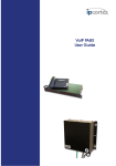
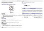
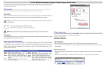
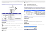
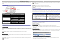
IS-IP290 Quick Guide
The Quick Guide is for quick installing and connecting the IS-IP290. For details, please refer to the IS-IP290’s User
NOTE: Check the status of the link indicator and activity indicator LEDs; if the LEDs are unlit, please check
Manual.
LAN connection.
Camera Rear Panel
Green Link Light indicates good network connection.
Orange Activity Light flashes for network activity indication.
Network LEDs
Before Login to the IS-IP290
A client program will be automatically installed on your PC when connecting to the IS-IP290. Before logging in to the
IS-IP290, please ensure downloading the ActiveX control is allowed by either changing the ActiveX controls and
Reset Button
plug-ins or setting Internet’s security level to default. For further details, please refer to the IS-IP290’s user manual.
Power LED
Definition
LINE OUT & LINE IN / MIC IN
Power LED
Reset button
NETWORK (with PoE)
Network LEDs
I/O
VIDEO (BNC connector)
SD (Micro SD Card slot)
AC 24V/DC 12V connector
Remarks
Two-way audio transmission
Power connection indication (green light).
Reset to factory default
RJ-45 connector
Network connection and activity indication
1 Output+
5 GND
2 Output-
6 D-
3 Input+
7 D+
4 Input-
For video output
For video and snapshots storage
+ AC 24V: Power-1
DC 12V: Power
AC 24V: Earth GND
DC 12V: Reserved
- AC 24V: Power-2
DC 12V: GND
IS-IP290 Installation
Please follow the instructions below to complete the Ethernet connection of IS-IP290.
ActiveX Controls and Plug-ins Settings
Step 1: Start the Internet Explorer (IE).
Step 2: Select <Tools> from the main menu of the
browser. Then Click <Internet Options>.
Step 3: Click the <Security> tab and select “Internet”,
and click <Custom level> to change ActiveX
settings.
Step 4: Set “ActiveX controls and plug-ins” items to
<Prompt> or <Enable>.
Internet Security Level
Step 1: Start the IE.
Step 2: Select <Tools> from the main menu of the
browser. Then Click <Internet Options>.
Step 3: Click the <Security> tab and select “Internet.”
Step 4: Down the page, press “Default Level” and click
“OK” to confirm the setting. Close the browser
window, and open a new one later for
accessing the IP Camera
IS-IP290 Login
The IS-IP290’s default IP address is: 192.168.0.250. Therefore, to access the IS-IP290 for the first time, set the
PC’s IP address as: 192.168.0.XXX; for example:
IP Address: 192.168.0.100
Subnet Mask: 255.255.255.0
Login ID & Password
• Key in the IS-IP290’s IP address in the URL bar of the Web browser window and press “Enter.”
Power up the Camera
To power up the IS-IP290, please plug the camera’s DC 12V/ AC 24V cable into the power terminal block.
• Enter the default user name (Admin) and password (1234) in the prompt request dialogue. Note that user name is
case sensitive.
Alternatively, connect the Ethernet cable to the camera’s PoE port and plug the other end of the cable into a PoE
Install the ActiveX Control
switch.
• After connecting to the IS-IP290, the request for installing the ActiveX control will appear just below the URL bar.
• Right Click on the information bar, and press “Install ActiveX Control…” to permit ActiveX control installation.
NOTE: If using PoE, make sure Power Sourcing Equipment (PSE) is in use in the network.
Ethernet Connection
Connect one end of the CAT5 Ethernet cable to the RJ-45 connector of the IS-IP290, and the other end of the cable
to the network switch or PC.
NOTE: In some cases, you may need to use an Ethernet crossover cable when connecting the IS-IP290
• In the pop-up security warning window, click “Install” to start downloading DC Viewer software on the PC.
directly to the PC.
• Press “Finish” after DC Viewer installation is complete.
10×/18x IS-IP290
Quick Guide
Browser-based
Viewer
The main page of the IS-IP290 user interface is shown as the figure below. Please note that function buttons will
vary depending on the camera model.
Ver1.2
00P5NH073ZXSEA2