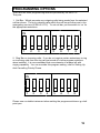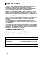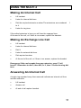
1
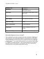
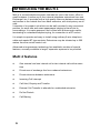
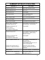
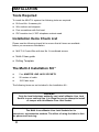
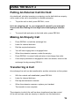
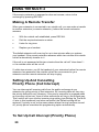
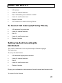
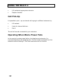
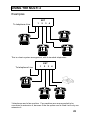
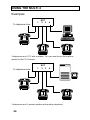
Telephone System
•
•
Installation Instructions
User Guide
Multimessage Systems
Ltd
1
2
CONTENTS
Contents
Technical Notes
3
4
Introducing the Multi 4
Summary of Multi 4 Features
6
7
MULTI 4 INSTALLATION
8
Programming Options
15
USING THE MULTI 4
Tones used by MULTI 4
16
Making an Internal / Exchange Line Call /
Answering An Internal Call
17
Answering An Exchange Line Call / Answering An Exchange
Line Call - When All Extensions Are Busy
18
Putting an External Call On Hold / Making an Enquiry Call /
Transferring a Call
19
Making a Remote Transfer / Setting Up And Cancelling Priority
Phone (Call Intercept)
20
Setting Up And Cancelling Do Not Disturb
21
Call Pickup / Operating When Mains Power Fails
22
Examples
23
In Case of Difficulty
25
Guarantee
27
MULTI 4 Drilling Template (Removable)
Centre
3
TECHNICAL NOTES
1
The Multimessage Systems MULTI 4 Telephone System is suitable for
connection to Exchange lines which provide Multi-Frequency (MF)
signalling. Multimessage Systems MULTI 4 can be used with Timed
Break Recall (TBR).
2
Only connect apparatus which has been approved for connection to
your analogue Public Switched Telephone Network. This will usually
have a lable with “APPROVED for connection to telecommunication
systems specified in the instructions for use subject to the conditions
set out in them”. Any other connection may cause damage or become
hazardous and will invalidate the approval of the apparatus if as a
result it then ceases to comply with the standards against which
approval was granted.
3
The Multimessage Systems MULTI 4 system is designed to operate
with a mains supply of 220-240Vac 47-63Hz with a maximum power
consumption of 16W.
4
The system is not suitable for use as an extension to a payphone.
5
Wiring from the Multimessage Systems MULTI 4 Box to the extensions
must be confined to the same premises and must not exceed a length
of 200 metres.
It is permitted to connect Multimessage Systems MULTI 4 as a
satellite to a PBX (Private Branch Exchange). However, satisfactory
performance cannot be guaranteed with every allowable combination
of host and subsidiary system.
6
7
Refer all servicing to qualified personnel or to the Multimessage
Systems Customer Servicing Department at the address given on the
back page of this handbook.
The line cord and mains cable must be disconnected before
removing the cover of the Multimessage Systems MULTI 4 Box.
8
4
TECHNICAL NOTES - cont’d
Exchange Line
MF REN of 3
Extensions
MF REN of 4
Dimensions
261mm long x 102mm wide x 63mm
deep (max)
Weight
1kg
Power Supply
220 - 240V AC 47-63 Hz
Plug Fuse Rating
3 Amp.
Power Consumption
16 watts maximum
Temperature
0 to 40°C working, -20 to +70°C
storage
Relative Humidity
0 to 95% (non-condensing)
(See notes below)
How many telephones can you connect?
This is important if you want to connect more than one piece of apparatus to
each extension. Each instrument (telephone, fax machine etc.) has a REN
(ringer equivalence number) value, which is usually written on it somewhere.
The total REN value of all instruments connected to an extension must not
be more than 4. If you have a BT telephone, you can assume that its REN
is 1 unless it is marked otherwise. If you connect telephones such that the
total REN value is more than 4 to one extension line, one or more of the
instruments will not ring and/or answer calls correctly.
5
INTRODUCING THE MULTI 4
Multi 4 is a small telephone system intended for use in the home, office or
small business. It serves up to four internal telephone extensions from one
Exchange Line. It provides both a high quality intercom between extensions,
and access to the outside line from each extension, with total privacy on all
calls.
It consists of a compact unit which can be wall-mounted in any convenient
position, its small size and smart appearance helping to blend into its
surroundings. It is mains powered, and is fitted with a three-metre cable,
terminating in a standard telephone plug, for connection to a BT socket.
It is simple to operate and easy to install using ordinary 2-wire telephone
cable and master BT-type sockets. Extensions may be situated up to 200
metres from the central control unit.
Advanced microprocessor technology has enabled a number of special
features, normally available in larger, expensive systems to be provided.
Multi 4 features
•
One external and one internal call or two internal calls at the same
time
•
Private use of exchange line from unbarred extensions
•
Private intercom between extensions
•
lncoming Call lntercept
•
Call Hold, Enquiry and Transfer
•
External Call Transfer to attended or unattended extension
•
Do Not Disturb
•
Call Barring
6
SUMMARY OF MULTI 4 FACILITIES
FACILITY
ACTION
Outgoing External Call
Dial 9 then external number
Internal Extension Call
Dial 1 to 4
Hold External Call
Press recall
Set Priority Phone
Dial 7 followed by own
extension number
Clear Priority Phone
Dial 70 from any extension
Set ‘Do Not Disturb’
Dial 0
Clear ‘Do Not Disturb’
Lift handset and then replace
Enquiry Call to Third Party
During an External Call
Press recall to hold external Call
Dial extension - make enquiry
To Return to External call:
a) After enquiry
b) If extension busy
c) If extension unobtainable
Press recall
Transfer External Call
Press recall to hold external call
dial extension - make enquiry
Replace handset
To Return to External Call :
a) If extension busy
b) If extension unobtainable
Press recall
Remote Transfer External Call
Press recall to hold external call
Dial extension
Listen for ring tone
Press recall if extension busy to
return to external call
Transfer will terminate after 2
minutes if no reply at extension
Otherwise replace handset
Answer external call at remote
extension
Power Failure
Connects extension 1 to external line
Emergency Calls - powered up
- power fail
Dial 9 999 or dial 9 112
Dial 999 or dial 112
7
INSTALLATION
Tools Required
To install the MULTI 4 system the following tools are required:
•
•
•
•
Drill and No. 8 masonry bit
Wire cutters and strippers
Pozi screwdriver with flat head
IDC insertion tool, if IDC telephone sockets used
lnstallation Items Check List
Please use the following check list to ensure that all items are available
before you commence installation.
•
MULTI 4 Control Box with two No. 8 roundhead screws
• Multi 4 User guide
• Drilling Template
The Multi 4 Installation Kit *
•
•
•
Four MASTER LINE JACK SOCKETS
50 metres of cable
100 Cable clips
The following items are not included in the Installation Kit :
WARNlNG
Only the local telephone authority can install a Master Line Jack
Socket to your external line. It is illegal for you to attempt to install
or tamper with this Master Line Jack Socket.
Please note :
The Multi 4 uses Master Line Jack Sockets for its
extensions, not extension sockets. The effect of using the latter is that
the phones will not ring.
8
INSTALLATION
•
•
•
•
Small screws to fix line jack sockets to wall/skirting board
Cable ducting, if required
Up to four approved telephones of the Multi-Frequency (MF) type
Master Line Jack Socket (to public exchange).
* This installation kit is required to complete the installation of the Multi 4. It
can be purchased as a comprehensive kit with the Multi 4 or separately from
an appropriate supplier.
If the public exchange line does not terminate in a Master Line Jack
Socket, your local telephone authority will connect one for you.
Site Requirements
Ensure that all of the following site requirements are adhered to:
•
Avoid locations that will expose the MULTI 4 to excess heat, dust,
excessive humidity and especially, damp and condensation, e.g. do not
install the MULTI 4 in bathrooms.
•
Avoid locations that are close to other electrical equipment such as motors
or switch gear.
•
Do not install extension sockets within 50mm of ac mains sockets,
neither must it share ac mains wall socket boxes.
9
INSTALLATION
Extension Cabling Requirements
Extension cabling must be made with single or multiple pair (PVC covered)
0.5mm diameter tinned copper wire with overall PVC sheath. Cable to BT
Specification CW 1308 is recommended. Multipair cable (e.g. 4-pair) is useful
when more than one extension is run in the same direction from the MULTI 4
Box. When the extension cables are being installed, the following instructions
must be followed:
•
Choose a route for the cable run that is safe from damage by feet, doors,
or other hazards.
•
Do not run the cable through areas which are exposed to damp or
condensation.
•
Use cable clips and secure the cable at intervals of 300mm.
•
Take care to avoid kinking or other damage to the cable.
•
Cable ducting may be employed for environmental protection or improved
appearance.
•
The cable must not be run closer than 50mm to mains electrical cabling,
neither must it share the mains wall socket boxes.
•
The maximum length of cable allowed from the Multi 4 Control Box to
each extension is 100 metres.
•
At the proposed site for the Multi 4 Control Box, leave at least 20cm of
spare cable for connection to the Multi 4 Control Box. Mark each cable
with its extension number.
•
The extension wiring must be kept separate from any other
telecommunications cabling.
•
Extension 1 must always be wired and connected as this is the power fail
telephone.
10
INSTALLATION
Mounting The Multi 4 Box
•
•
•
•
The Multi 4 box should be mounted horizontally or vertically with
connectors to the bottom with a minimum of 75mm clearance at the base
of the box. Refer to the diagram below.
Using the template supplied (see the centre of this handbook), locate and
mark the centre position of the two fixing screws. Drill, and if necessary,
plug the fixing holes.
Screw in the roundhead screw that will fit into the keyhole slot, so that the
screw head protrudes by approximately 2mm from the wall.
Undo the retaining screw and remove the cover from the end of the box .
Caution:
The equipment is fitted with semiconductor devices which may be damaged
by static electricity discharged by people, tools or test gear. To prevent
damage, ensure that no contact is made with any of the electronic circuitry,
when installing the equipment.
•
•
•
To prevent damage to the equipment you should heed the following:
Place the box over the screw you have placed in the wall, such that the
screw drops into the keyhole slot. Slide the box to lock the screwhead into
position. If necessary adjust the screw to ensure that the box is held firmly
to the wall. Insert and screw the retaining screw. Refer to the diagram
below.
Do not connect the mains supply or the exchange line.
WARNING: Do not remove top cover, hazardous voltages inside.
No serviceable parts. If removed all
Position of retaining screw
(remove cover to gain access)
Key hole slot on rear of Multi 4 Box
Programming
switch
11
INSTALLATION
Wiring Extension Sockets
•
Remove the cover from the line jack sockets by releasing the two
holding screws. Refer to the diagram below.
If necessary drill and plug the wall at the positions of the mounting
holes on the back of the socket. Pierce one of the cable entry points
and screw the socket to the wall using two fixing screws. Feed the
cable into the socket .
Remove approximately 5cm of sheath from the cable. Bare 5mm of
wire and connect the wires to the terminal block position 2 and 5,
ignoring colour coding of cables.
Replace and secure the cover of the line jack socket.
Run cable back to Multi 4 Control Box and cut off, leaving sufficient
cable for termination
Repeat the procedure for Master Sockets 2-4.
•
•
•
•
•
Position 5
Fixing screws
Break-out
panels (for
cable entry)
TYPICAL MASTER SOCKET
Screw
Position 2
12
INSTALLATION
Connecting The Wires
To wire the extension cables to the Multi 4, sequentially perform the following:
•
Unscrew the two retaining screws from the extension cable clamp and
remove the clamp. Refer to the diagram below.
•
Feed the extension 1 cable into the Multi 4 box through the hole in the
end. Extension 1 is the power fail phone and therefore must always be
wired.
•
Remove approximately 15mm from the extension cable sheath and
bare approximately 5mm from the end of each wire.
•
Using a small screwdriver, connect the ends of the cable to the
terminal block as shown in the diagram below.
•
•
Repeat the procedure for extension cables 2 to 4.
•
Set the call bar and priority phone options if required (see
‘Programming Options’, Page 5)
On completion, ensure that the extension cables slide into the retaining
slots moulded in the base of the box. Refit the cable clamp.
Programming switch
Extension 1-4
terminal block
Extension
cable
clamp
Main line cord
Extension cables 1-4
13
INSTALLATION
Checking Out The System
•
•
•
•
•
•
•
•
•
Ensure that all the phones are operative, set to Tone and Timed break
recall (usually marked as T, TB, DTMF& TBR,MF&TBR). Please note that
the Multi 4 does not support the use of phones which are PULSE, LOOP
DISCONNECT (LD) or EARTH RECALL(E,ER).
Check there are no wiring mistakes and that all the extension phones are
plugged in.
Plug in the Multi 4 ac mains lead and switch on. Do not plug into the
exchange line master socket yet.
Make an internal call from one extension to another.
Ensure that the ringer works correctly and that the speech is clear and
noise free. Repeat this procedure to check all the extensions.
Switch off the power to the Multi 4 and plug the exchange line cord into
the exchange line master jack socket.
Lift the handset at extension 1 - you should hear the public exchange dial
tone. Now make an outside call to check the exchange line. Replace
handset.
Switch on the mains power again.
Make another outside call from extension 1. This time dial 9 followed by
the external number. Refer to Using the Multi 4 section of this handbook.
If a fault is found during the above, switch off the mains power, remove the
exchange line cord from its socket and check that the wiring is correct.
Under no circumstances must the cover of the Multi 4 be removed
without first disconnecting the ac mains and removing the exchange
line cord.
14
PROGRAMMING OPTIONS
There are two main programming features provided by the MULTI 4.
They are:
1. Call Bar - Which prevents any outgoing calls being made from the selected
call bar phone. The only outgoing calls which the call bar will allow are to the
emergency services (9 999 or 9 112). To set call bar, put the switch to ‘on’ for
the appropriate extension.
ON
1
2
3
4
5
6
7
8
2. Ring Bar on incoming calls - If you do not require certain extensions to ring
on incoming calls then the ring can be turned off via the program switches
when installed. It is recommended that one extension is always left with
ringing capability. You can override this program setting, refer to Setting Up
And Cancelling Priority Phone.
ON
1
2
3
4
5
6
7
8
Please use a suitable instrument when setting the program switches e.g a ball
point pen.
15
USING THE MULTI 4
The MULTI 4 offers the user many powerful features not available when
telephones are connected through ordinary parallel extensions.
Furthermore, this has been achieved without sacrificing the incomparable
economy and versatility offered by simple, standard telephones.
Because of this, your telephone keypad is called on to perform many more
functions than the customer dialling of another subscribers number. The
telephone now has a second function as a control panel, putting options such
as intercom / outside line and hold / transfer at your fingertips.
Fortunately, the MULTI 4 has been designed so that the control functions are
simple to perform and easy to remember. Nevertheless, it is necessary to be
a little more careful when using the MULTI 4 than when using a basic
telephone.
This is because wrongly or inadvertently dialled digits which normally are
easily corrected merely by replacing the handset can program the MULTI 4 to
an undesired mode.
For instance , if you should start to dial an outside number without first dialling
9, you may accidentally set Priority or Do not Disturb. If you suspect that this
has happened, you can quickly cancel these settings by raising your handset
and dialling 70, as described later in this guide.
Tones Used By The Multi 4
When your telephone is connected through MULTI 4 to the outside line, you
will hear the usual BT tones for Ringing, Engaged (Busy), and Number
Unobtainable, with the exception of Dial tone which is generated internally.
The following tones are used :
Internal Dial Tone
Continuous purring sound
Internal Ringing Tone
Repeated double burst of dial tone
Engaged Tone
Repeated single burst of high note
Number Unobtainable
Continuous high note
Confirmation Tone
Alternating notes, short and long
16
USING THE MULTI 4
Making An Internal Call
•
Lift handset.
•
Listen for internal dial tone.
•
Dial the required extension number.The extensions are numbered
to 4.
•
Listen for ring tone.
If the called extension is busy you will hear the engaged tone.
At the end of the call, or if there is no answer, replace the handset.
Making An Exchange Line Call
•
Lift handset.
•
Listen for internal dial tone.
•
Dial 9.
•
Listen for external dial tone.
•
Dial required number.
•
At the end of the call, or if there is no answer, replace the handset.
Emergency Calls can be made from any extension, even if "call
barred". Remember to dial 9, then 999, or 9, then 112 after hearing dial
tone.
Answering An Internal Call
A single ring repeated every three seconds indicates an internal call from
another extension.
•
Lift handset.
•
Answer call.
•
At end of call replace handset.
17
1
USING THE MULTI 4
Answering An Exchange Line Call
An incoming call from the exchange line causes all extensions to ring, unless
call intercept (priority phone), do not disturb, or no incoming calls are set.
A double ring repeated every three seconds indicates an outside call.
If you can hear more than one extension, you will notice that the
sounds do not coincide. The sequence Is:
Extensions 1 and 3 ring together, then
Extensions 2 and 4 ring together.
However, each individual telephone gives a double ring every three seconds,
exactly as if it were connected directly to the exchange line.
The ringing sequence continues until the call is answered or the caller
abandons the call attempt.
Picking up any of the extension telephones which is ringing will answer the
call. If your extension is not ringing then you can answer the call by :
•
Lifting the handset
•
Listen for internal dial tone
•
Dial 6
Remember to replace the handset at the end of the call.
Answering An Exchange Line Call When All Extensions Are Busy
When an incoming call arrives when all the extensions are busy on an internal
call, a warning tone will be heard on both extension 1 and the connected
extension. The tone will stop as soon as another extension answers the call.
If the call remains unanswered either extension 1 or its connected extension
should be used to answer it.
•
Pressing hook switch once (to terminate internal call)
•
Releasing hook switch
•
Answer incoming call
18
USING THE MULTI 4
Putting An External Call On Hold
An outside call, whether incoming or outgoing, can be held while an enquiry
call is made or the call is transferred to another extension.
•
To put the call on hold, press RECALL, once.
If it is an outgoing call, i.e. you originated it yourself, you must wait
20 seconds after dialling the last digit before attempting to hold the
call.
•
To cancel hold and return to the held caller, press RECALL.
Making An Enquiry Call
•
Press RECALL to hold the exchange line.
•
Listen for internal dial tone.
•
Dial the required extension.
•
You will hear ringing tone or engaged tone.
•
When the extension answers, make the enquiry.
•
Press RECALL to cancel hold and return to exchange line caller
•
If the enquiry extension is engaged or does not answer, return to the
exchange line by pressing RECALL.
Transferring A Call
An exchange line call can be transferred to another extension on the system.
•
With the outside call established, press RECALL.
•
Listen for internal dial tone.
•
Dial required extension number.
•
When the extension answers, replace your handset
The transfer is now complete.
The extension to which the call has been transferred now has control
of the call and can make an enquiry or transfer to a third extension.
19
USING THE MULTI 4
If the enquiry extension is engaged or does not answer, return to the
exchange by pressing RECALL.
Making A Remote Transfer
When your extension is connected to an outside call, you can make a transfer
to another extension (a remote extension), before the remote extension
answers.
•
With the outside call established, press RECALL.
•
Dial the required extension number.
•
Listen for ring tone.
•
Replace your handset.
The dialled extension will now ring for up to two minutes after you replace
your handset. If the remote extension answers within two minutes the outside
call will automatically transfer to it.
If the call is not answered within two minutes then the call will "clear down" i.
e. the outside caller will be cut off.
If, within two minutes, you lift the handset of your extension before the remote
extension has answered, the outside call will be reconnected to your
extension and the remote extension will stop ringing.
Setting Up And Cancelling
Priority Phone (Call Intercept)
You can intercept all incoming calls from the public exchange at one
extension by giving priority to that extension. All incoming calls will then ring
the priority extension only However, if the priority extension is engaged when
an incoming call arrives , then all other extensions will ring in the normal way.
This function will over ride the incoming ring setting (see Setting Up The Multi
4, later in this handbook) and when cancelled, the Default setting will be
restored. If priority is set on the same phone where the ring has been turned
off, priority phone overrides this programming option automatically.
To Set Up Call lntercept (Priority Phone)
20
USING THE MULTI 4
•
Lift handset.
•
Listen for internal dial tone.
•
Dial 7 followed by own extension number
•
Listen for confirmation tone.
•
Replace handset.
•
Your extension is now the Priority Phone
To Cancel Call lntercept (Priority Phone)
•
Lift handset of any extension
•
Listen for internal dial tone
•
Dial 70.
•
Listen for confirmation tone.
•
Replace handset
Setting Up And Cancelling Do
Not Disturb
Any or all of extension 2 to 4 may be set up to Prevent ringing at
that extension.
To set up Do Not Disturb.
•
Lift handset at appropriate extension
•
Listen for internal dial tone.
•
Dial O.
•
Listen for confirmation tone.
•
Replace handset.
Ringing is now disabled ot that extension for both internal and external calls.
To cancel Do Not Disturb.
21
USING THE MULTI 4
•
Lift handset at appropriate extension.
•
Replace handset.
Call Pick-Up
It is possible to pick - up an external call ringing at a different extension by:
•
Lift handset
•
Listen for internal dial tone.
•
Dial 6.
The call will now be connected to your extension.
Operating When Mains Power Fails
In the event of a mains power failure, the telephone at extension 1 is
connected directly to the exchange line. The line is then accessed from this
extension without dialling 9. The other extensions will not function.
22
USING THE MULTI 4
Examples
To telephone Line
1
EXT
2 3
4
This is a basic system arrangement, with 4 standard telephones.
To telephone Line
1
EXT
2 3
4
3 telephones and a fax machine. Fax machines are recommended to be
connected to extension 4, because if the fax option card is fitted it will only use
extension 4.
23
USING THE MULTI 4
Examples
To telephone Line
1
EXT
2 3
4
3 telephones and 1 PC with a modem. You can also have a fax machine
parallel to the PC if desired.
To telephone Line
1
EXT
2 3
4
3 telephones and 1 answer machine with another telephone.
24
USING THE MULTI 4
In Case Of Difficulty
These notes should be of assistance, if you ever encounter any difficulty in
using the MULTI 4.
Remember that an outside call cannot be made from a call barred extension
(other than a 9 999 or 9 112 call) - make sure that the Call Barring settings
are set to your requirements.
Be careful not to leave an outside call on hold by accident. If in doubt press
recall to check. If public network dial tone is received, clear the system by
replacing the handset.
Ensure that call intercept is set correctly, and not set accidentally. If in doubt
dial 70 at any extension to cancel.
Ensure that do not disturb has not been set accidentally. Cancel by lifting
and replacing the handset at the relevant extension.
Replace the handset after an outside call even if the other party clears down
first and you receive dial tone.
Remember the timing features of the system:
When originating an outside call you must wait at least twenty seconds after
dialling the last digit, before attempting to place a call on hold.
When an outside call is put on hold and the extension replaced, the outside
call will remain on hold for up to two minutes. During this time the call can
only be accessed from the original extension.
At the end of the preset time the line will be released and the system reset.
If, after investigating the above possibilities, you still cannot obtain an outside
line, proceed as follows:
Switch off the mains power to the MULTI 4, and after waiting at least ten
seconds switch on again. If the fault has not cleared, unplug the MULTI 4
from the Exchange line socket, and plug in the Extension 1 phone in its place.
If dial tone is still not obtained, try a second telephone. If this is unsuccessful
then the line may be assumed to be faulty, and you should contact the
telephone company e.g. BT.
25
When using speed Dial/modem it is important to make sure that you program
a pause after dialling 9. Please refer to the manufacturers user guide.
If after installing the system the extensions do not ring, please check that
Master Line Jack Sockets have been used.
26
GUARANTEE
Multimessage Systems Ltd. guarantees this product for one year from the date of purchase provided that:
•
•
•
The product has only been used for its intended purpose, and has not been subjected to misuse, or been
wilfully or accidentally damaged.
The product has been installed according to the maker's lnstallation Instructions.
The product has not been tampered with or repaired by anyone other than Multimessage Systems Ltd. or its
approved agents.
If a fault occurs in this product within twelve months of purchase you should return it to where you bought it, together
with the sales receipt, and it will then be replaced or repaired free of charge.
27
Dealers stamp
APPROVED for connection to
telecommunication systems specified
in the instructions for use subject to
the conditions set out in them.
504391
Multimessage Systems Ltd.
Unit 2 / 3, Furzewood House,
Cranborne Industrial Estate,
Cranborne Road, Potters Bar,
Herts. EN6 3JN
Tel. ++44 (0) 1707 644480
Fax ++44 (0) 1707 646745
Part No. 955003100
Issue 2