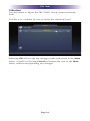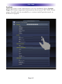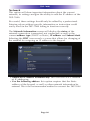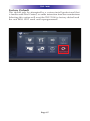
1
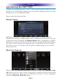
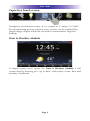
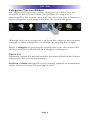
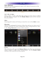
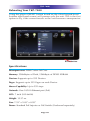
Owner's Manual
TKP-7000
Network Keypad
TKP-7000 Owner's Manual ©2012-2014 Universal Remote Control, Inc.
The information in this owner’s manual is copyright protected. No part of this
manual may be copied or reproduced in any form without prior written consent
from Universal Remote Control, Inc.
UNIVERSAL REMOTE CONTROL, INC. SHALL NOT BE LIABLE FOR OPERATIONAL, TECHNICAL OR EDITORIAL ERRORS/OMISSIONS MADE IN
THIS MANUAL.
The information in this owner’s manual may be subject to change without prior
notice.
URC - Control the Experience is a registered trademark of Universal Remote
Control, Inc.
Total Control is a registered trademark of Universal Remote Control, Inc.
All other brand or product names are trademarks or registered trademarks
of their respective companies or organizations.
Universal Remote Control,Inc.
500 Mamaroneck Avenue, Harrison, NY 10528
Phone: (914) 835-4484 Fax: (914) 835-4532
TABLE OF CONTENTS
Introducing the TKP-7000
1
Installing the TKP-7000
3
Installation
4
Main Menu Navigation
5
Rooms Menu
12
Time & Weather Module
16
Shortcuts Pop-Up
17
Adjusting User Settings on the TKP-7000
19
Rebooting Your TKP-7000
28
Specifications
28
Limited Warranty Statement
29
End User Agreement
31
Federal Communication Commission
Interference Statement
32
Regulatory Information to the user
33
TKP-7000
Introducing the TKP-7000
Thanks for purchasing URC's TKP-7000 in-wall touch-screen. Its easy,
intuitive use will help simplify your life while adding control of more
things than you thought possible.
Enjoy some key features like:
Rooms Menu
With the touch of a single button, take control of your domain.
Besides the ability to temporarily link the different rooms/areas of your
system for music listening, the Rooms Menu offers a snapshot of “what's
going on” in every room of your Total Control system. Better yet, tapping
on a room will convert your keypad into a controller for THAT room.
See how easy it is to keep track of what's happening in your world…
and control it!
Shortcuts Pop-Up
With all of the different options to choose from, the Shortcut PopUp allows you to save some of the most common devices/activities
for easy selection. Keep up to 6 different activities at your fingertips
with the Shortcuts Pop-Up menu.
Page 1
TKP-7000
Capacitive Touch screen
Navigation just became easier; it's as simple as a “swipe” or “flick”.
By incorporating gesture control, every screen can be explored by
simple finger swipes while the on-board accelerometer supports
flicking.
Time & Weather Module
A simple button press opens the Time & Weather Module; a full
screen display keeping you “up to date” with today's time, date and
weather conditions.
Page 2
TKP-7000
Installing the TKP-7000
The TKP-7000 is wall-mountable and fits easily into a dual-gang
opening. Prior to installation, make sure power is available at the
preferred location.
Power can be supplied to the TKP-7000 in any of the following
ways:
=
An Ethernet cable connected to a PoE (power over ethernet)
router/switch
=
An Ethernet cable connected to a PoE (power over ethernet)
injector
Power over Ethernet or PoE technology describes a system to pass
electrical power safely, along with data, on Ethernet cabling. The
IEEE standard for PoE requires Category 5 cable or higher for high
power levels.
Page 3
TKP-7000
Installation
Follow the diagram below for installation:
1. Make sure the dual-gang opening is fitted with a standard twogang trim box (available from the local electrical supplier/store)
2. Connect the Ethernet cable to the rear of the supplied TKP-7000
wall-plate.
3. Mount the wall-plate to the two-gang retro-box
4. The TKP-7000 easily snaps into place to the wall-plate.
Page 4
TKP-7000
Main Menu Navigation
Although specific screen design and certain options will be dictated
by the custom integrator that programmed the Total Control System,
the general layout will remain the same. Actual navigation is performed
through screen swipes (Up/Down, Left/Right) while selecting any item
is as simple as pressing the icon/text to be selected.
Light Sensor
The MAIN menu screen may be programmed any number of ways,
however, the general layout will remain the same
Page 5
TKP-7000
Title Bar
The Title Bar will be present on all TKP-7000 screens and contains
valuable information during normal use. Easily find out the time,
weather, now playing information and the room that the keypad is
controlling.
Time & Weather
This data, found on the left-hand side of the Title Bar will show the
current time, date and weather information. Pressing this area of the
Title Bar will open the Time & Weather Module. For more
information about this module, refer to the Time & Weather Module
section, later in this manual.
Current Room
The current room portion of the Title Bar shows the room that the
TKP-7000 is controlling. Remember, in a Total Control system,
although each room's keypad will default to control the room in
which it is placed, using the Rooms Menu will allow it to control
any other room in the your system.
Page 6
TKP-7000
Now Playing
Appearing on the right-hand side of the Title Bar, this displays the
source that is currently being used in the room that the keypad is
controlling.
• The Now Playing display will show the device that is being used
(in this case, William's iPod), associated artwork, and metadata
information is displayed since it is a URC media device.
The metadata will change, every 5 seconds, rotating
between song, artist and album.
• If an activity is being performed (like DVD or Cable) in the
selected room, the Now Playing section will display the activity.
If an activity is being performed in the selected room, the Now
Playing bar will describe the activity.
Page 7
TKP-7000
Categories/Devices Ribbon
This ribbon will show the various categories of control that are
available to the selected room. The quantity of categories is
determined by the system setup and can vary from one to however
many categories were programmed by the system designer.
Although only seven categories can fit on the screen at any moment,
navigate to other categories, if available, by swiping left or right.
Select a category by pressing the appropriate icon; this reveals the
devices/activities available for that category (submenus).
Device List
Submenus contain the devices/activities that were placed in the chosen
category by the system programmer.
Scroll up or down through the list by swiping upwards or downwards,
select a device/activity by pressing its icon.
Page 8
TKP-7000
Status Bar
The Status Bar, located directly above the Core Buttons, provides
valuable status and feedback of the Total Control system. The four
sections of the Status Bar are determined by the system
programmer, and are customizable per keypad,so it is not possible
to explain how your keypad looks; however, after reviewing the
following possibilities, there should be no need for further explanation.
Sunrise Time: Updated at midnight every day, this will show the
sunrise time for the next day.
Sunset Time: Updated at midnight every day, this will show the
sunset time for the next day.
URC Thermostat Temperature: If a THZ-100 (URC's thermostat) is
included in your home, this will show the current temperature status
based upon the internal sensor, additional sensor or the mean
temperature of both.
Alarm Clock: If the room being controlled has an Alarm that is set
to activate for that room the status bar will display an alarm clock
icon and the next scheduled time/day.
Surround Mode: When used with URC's DMS-AV Surround Processor
this will display the current surround mode of the processor.
Room Linked Status: Whenever the chosen room/area is “linked” to
other rooms, this will show a link
acknowledgment and icon.
Weather Alerts: Based on the current location entered by the system
programmer, the words “weather Alert” will appear
if an automatic alert is received via internet.
Vacation Mode: Whenever the Vacation Mode is activated for the
Total Control system, the status bar will display “Vacation Mode:
ON”.
Page 9
TKP-7000
Core Buttons
These key system navigation buttons will always be present at the
bottom of the screen.
Vol-, Vol+ & Mute
These audio controls will affect the volume for the room to which
the TKP-7000 is assigned. See the Rooms Menu section of this manual
for more details.
Main
Selecting this button will always return the user to the Main screen
Shortcuts
These user-configurable shortcuts allow the end-user to store up to 6
favorite activities. For more information about using shortcuts, refer
to the Using Shortcuts section of this manual.
Rooms
This selection will open the Rooms Menu and allow for monitoring
and/or control of other rooms in the project. See the Rooms Menu
section of this manual for more details.
Page 10
TKP-7000
Power
When pressed, this performs the Room Off function programmedby
the custom integrator.
If this button is pressed for greater than 3 seconds, the Power Menu
appears.
In this menu, it is possible to:
• Turn Off the ROOM (this is the same as tapping the Power button).
• Issue the House Off command, as programmed by the custom
integrator.
• Custom commands, programmed by the custom integrator, may
also appear in this menu.
Page 11
TKP-7000
Rooms Menu
The Rooms Menu is the “landing” screen for a TKP-7000. This menu
(see picture below) will be displayed whenever the keypad reboots,
loses/regains power or is reset. The most common choice would be
to select the room where the TKP-7000 is physically located,
however, as we will discover, this is up to the user.
The Rooms Menu is used to:
• Temporarily Link rooms in a Total Control DMS system. This
allows all of the linked rooms to listen to the same audio source
and join the volume commands into a single interface.
• Monitor the status of other rooms in the Total Control project
• Control any other room in a Total Control project as if it were a
keypad in that room. This is dependent upon the programming
done by the custom integrator.
Links
Options
Rooms
Room List Buttons
• Each room listing will have an associated box and action buttons.
• The Exit button will return the user to the last screen used
• Selecting the room name will allow for control of that room (see
Selecting a Room)
Page 12
TKP-7000
Initial View (Room Monitoring)
When the Rooms Menu opens up, the room list populates with all
of the rooms in the Total Control project. Each room displays its
status so the user can visually see what is “going on” in that room.
The Exit button will return the user to the previous screen.
Selecting a Room (Room Control)
Selecting any room from the room list will allow the TKP-7000 to
control that room, as if it were physically in that room.
Returning the keypad to control the room where it is physically
located requires accessing the Rooms Menu and selecting the
appropriate room.
Page 13
TKP-7000
Linking Rooms (DMS Audio only)
Selecting the Link Rooms button will open up the Link Rooms
screen with the current room already selected. Only rooms/areas
that are part of the DMS family of products will appear.
Select, using the check boxes, the rooms that you would like to
LINK. Pressing the check box will alternately “check” and
“uncheck” it.
= The Go Back button will cause the screen to revert to the Room
Menu without making any changes.
= The Done button will temporarily save the checked rooms as a
linked group that can be controlled from any of the linked
rooms.
=
Linked rooms are saved until the power is turned OFF, or the user
manually de-links the room(s).
Page 14
TKP-7000
Using Linked Rooms
Once a room is linked, pressing the volume or mute buttons for that
room will cause the Linked Rooms Volume Pop-Up to display
This menu will display the volume levels for all rooms in the
temporary group.
Selecting All Linked Rooms results in the volume and mute
commands to operate ALL rooms (e.g. Volume Up will cause
the volume in all linked rooms to rise simultaneously, and at
the same rate).
= Selecting an individual room in the Linked Room List allows
the volume and mute buttons to adjust sound ONLY for the
room chosen.
=
Room Options
Selecting the Room Options button for a room will cause the menu
to expand and offer the user various options to control the room.
Lights Off: If URC controlled lights are located in the selected
room, the Options menu will display a light bulb icon. Selecting
this icon will issue a “lights off” command for the chosen room.
= Power Off: Selecting the power icon will issue a “room off”
command for the selected room. The default for this command
is to turn off all audio and video device in that room, however
this may have been altered by the system programmer.
=
Page 15
TKP-7000
Time & Weather Module
This module displays information about the time, date and local
weather.
Pressing on the Time, Date & Weather display in the Title Bar of the
TKP-7000 opens the Time & Weather Module.
=
Selecting Exit will return to the previous screen
=
Selecting Night Mode will place the TKP-7000 into a low light mode
to prevent it from overpowering a dark room. This mode will disable
any photo slideshow or screen time-out time andremain in this mode
until touched again.
=
Once touched, the screen will revert to its normal mode of operation, including displaying a photo slide show and turning Off
after the amount of time determined in the Settings Menu.
Page 16
TKP-7000
Shortcuts Pop-Up
The Shortcuts Pop-Up menu is designed to give the user the ability
to select their most frequently used devices/activities and place
them within an easy to reach menu.
There are a maximum of six (6) shortcuts per room location.
Remember, regardless of the physical location of the TKP-7000, it
may still access, via the Rooms menu, any of the other rooms in the
Total Control system (dependent upon programming). Each room
can be assigned up to 6 shortcuts in this menu.
Only items that appear in the currently selected room are available
to be added to the Shortcuts Pop-Up.
Using the Shortcuts Pop-Up
Select the Shortcuts Pop-Up by pressing the Shortcuts icon in the
Core Menu.
If the screen is not touched, after 60 seconds the Shortcut Popup
will close and the TKP-7000 will revert to its previous screen.
Selecting a shortcut is the same as navigating to that same icon
(within the submenu) and selecting it.
Add devices/activities to this menu by selecting the Add/Edit button
in the Shortcut Popup.
This opens the Shortcuts Add/Edit screen, which will allow the user
to scroll through all of the devices/activities available to that room.
Page 17
TKP-7000
Select up to 6 devices/activities by selecting the check box shown
for each possibility. Once all 6 are chosen, the remaining
devices/activities will be grayed out to show there are no more
choices to be made.
Reorder devices by selecting the reorder icon at the top of the
Add/Edit window; this opens the reorder Items list.
If you would like to change the order in which the activities/devices
appear, drag the items, using the “grabber” on the right side of the
boxes to rearrange them.
If you would like to remove an item from the list, select the X
(delete) icon to the left of the device/activity name.
Selecting the Go Back option will revert to the Add/Edit screen
without making any changes
Selecting the Save option will make the requested changes and
revert back to the Add/Edit screen.
Page 18
TKP-7000
Adjusting User Settings on the TKP-7000
By pressing and holding the Main and Mute buttons for 5 seconds
(found in the Core Menu) simultaneously the TKP-7000 Settings
Menu will appear.
Simultaneously press both the Main and Mute buttons to activate
the Settings Menu.
Settings Menu
The Settings Menu allows you to adjust some basic parameters of
the TKP-7000 keypad.
Select these options by pressing the appropriate icon. If no
icon/button is pressed for 45 seconds, the unit will revert back to
the Main screen.
The Settings Menu is broken down into the following categories:
Sleep Settings: Manages how long the LCD remains ON after
usage.
General: Contains settings for Time, Date and Temperature Scale
Sound: Allows control of any confirmation beeps, or the ability
to disable these tones.
Brightness: Easily adjust the LCD screen's brightness level, and
enable/disable the light sensor.
Vibration: Adjust the touch screen’s vibration sensitivity.
System: Quickly view the Memory Usage, Firmware Version
and other details about the TKP-7000.
Network: View information about the current network as well
as set a Dynamic or static IP address for the TKP-7000.
Factory Default: Reset the TKP-7000 to factory settings.
Page 19
TKP-7000
Sleep Settings
Decide upon the option that best fits the current needs.
LCD Screen is always ON: This option keeps the LCD screen
illuminated at all times
LCD Screen will turn OFF: This option allows the user to decide on
the amount of time that the LCD screen will remain illuminated
after it is last used. The + and – buttons will adjust the time frame
up or down accordingly.
LCD Screen will display a screen saver
This option will display a screen saver of the photos found on the
online website, Picassa. This will start display after the time frame
selected in the Start After box, and will continue for the amount of
time dictated in the Duration box.
Selecting OK will accept any changes made and return to the Main
menu, as well as selecting Cancel will return the user to the Main
menu, without incorporating any changes.
Page 20
TKP-7000
General
The General settings screen allows for setting the Time, Date and
decide on the scale used to display the temperature(Fahrenheit/Celsius).
To view the rest of the General settings menu, be sure to scroll up/down.
Using the arrow found at the left and right sides of each property
(hour, minutes, month, etc.) adjusts the value up, or down, respectively.
Selecting OK will accept any changes made and return to the Main
menu, as well as selecting Cancel will return the user to the Main
menu, without incorporating any changes.
Page 21
TKP-7000
Sound
By default, the TKP-7000 emits a low volume beep as a confirmation
tone for screen presses. Use this menu to adjust thesound to your liking.
Use the + or – buttons to raise or lower the volume of the confirmation
beep.
Selecting OK will accept any changes made and return to the Main
menu, as well as selecting Cancel will return the user to the Main
menu, without incorporating any changes.
Page 22
TKP-7000
Brightness
Determine the overall brightness of the TKP-7000's display, or
incorporate a light sensor that will adjust the brightness of the unit
based upon ambient room lighting.
Use the + or – buttons to raise or lower the level of brightness.
Selecting Enable Light Sensor disables the Brightness Level selection
and dynamically adjust the LCD brightness based upon the ambient
room lighting detected by the light sensor.
Selecting OK will accept any changes made and return to the Main
menu, as well as selecting Cancel will return the user to the Main
menu, without incorporating any changes.
Page 23
TKP-7000
Vibration
Use this menu to adjust the TKP-7000’s touch screen sensitivity
level.
Use the + or – buttons to raise or lower the sensitivity level.
Selecting OK will accept any changes made and return to the Main
menu, as well as selecting Cancel will return the user to the Main
menu, without incorporating any changes.
Page 24
TKP-7000
System
Although none of the information can be modified, these System
Pages will show important information about your TKP-7000. These
pages should only be needed by a custom install professional, or
technical support.
Page 25
TKP-7000
Network
This option will show important information about the current
network, its settings and give the ability to edit the IP address of the
TKP-7000.
Be careful, these settings should only be edited by a professional.
Entering values without specific information or instruction could
easily result in the TKP-7000 failing to function correctly.
The Network Information screen will display the status of the
network connection (connected, not connected) as well as the
current address type (DHCP or Static), IP address and Subnet Mask.
Selecting the EDIT icon reveals a screen that allows for changing of
the method for assigning an IP address to the keypad.
• Obtain an IP address automatically: this uses the DHCP method
of IP addressing
• Use the following address: this option requires that the Static
address of the keypad, as well as other network information be
entered. This is the recommended method to connect the TKP-7000
Page 26
TKP-7000
Factory Default
This should only be attempted by a custom install professional that
is familiar with Total Control, or under instruction from the manufacturer.
Selecting this option will reset the TKP-7000 to factory default and
the unit WILL NOT work until reprogrammed!
Page 27
TKP-7000
Rebooting Your TKP-7000
Using the physical RESET button found on the silver keypad bezel
(bottom right-hand corner) will power-cycle the unit. This is the first
option to try, if the screen freezes or the unit becomes unresponsive.
Reset button
Specifications
Microprocessor: ARM Cortex-A8 Core
Memory: 256Mbytes of Flash, 256Mbyte of DDR2 SDRAM
Devices: Supports up to 255 Devices
Pages: Supports up to 255 Pages on each Device
Macro Capability: Up to 255 steps
Network: One 10/100 Ethernet port (PoE)
LCD: 7 inch (1024x600)
Weight: 12.37 oz
Size: 7.53” x 5.02” x 0.92”
Power: Standard PoE Injector or PoE Switch (Purchased separately)
Page 28
TKP-7000
Limited Warranty Statement
1. Limited Warranty and Disclaimers
Universal Remote Control, Inc. (“URC”) warrants that the URC equipment shall
be free from defects in material and workmanship under normal usage for two
(2) years from purchase when such is purchased from URC. This limited
warranty is valid only in the United States of America. URC warrants that the
software will substantially conform in any material respect to its functional
specifications at the time of delivery. URC SHALL NOT BE LIABLE FOR
OPERATIONAL, TECHNICAL OR EDITORIAL ERRORS AND/OR
OMISSIONS MADE IN THE URC DOCUMENTATION. URC DOES NOT
WARRANT THAT THE URC SOFTWARE IS BUG-FREE OR ERROR FREE OR
THAT THERE ARE NO ERRORS/BUGS IN THE URC SOFTWARE.
URC warrants that at the time of purchase the URC equipment and the URC
software complied with all applicable regulations and policies of the Federal
Communications Commissions (“FCC”) regarding electromagnetic interference
caused by electronic/computing devices and to the extent that the URC
equipment and/or the URC software fails to so comply, URC shall, at its own
expense, take all reasonable measures to promptly cause such to comply.
URC equipment purchases from other than an authorized URC dealer or
distributor are without warranty.
THIS LIMITED WARRANTY DOES NOT COVER TECHNICAL ASSISTANCE
FOR HARDWARE OR SOFTWARE USAGE EXCEPT AS EXPRESSLY
PROVIDED FOR HEREIN, THE EQUIPMENT, SOFTWARE AND
DOCUMENTATION OF URC ARE SUPPLIED “AS IS” WITHOUT ANY
WARRANTY, EXPRESS, STATUTORY OR IMPLIED, OF ANY KIND. TO
THE MAXIMUM EXTENT PERMITTED BY APPLICABLE LAW, URC
EXPRESSLY DISCLAIMS ALL WARRANTIES, EXPRESS, STATUTORY OR
IMPLIED, INCLUDING BUT NOT LIMITED TO THE WARRANTIES OF
MERCHANTABILITY AND FITNESS FOR A PARTICULAR PURPOSE. URC
DOES NOT WARRANT, GUARANTEE, OR MAKE ANY
REPRESENTATIONS REGARDING THE USE OF, OR THE RESULTS OF THE
USE OF, THE EQUIPMENT, SOFTWARE OR DOCUMENTATION IN
TERMS OF CORRECTNESS, ACCURACY, RELIABILITY OR OTHERWISE.
EXCEPT AS EXPRESSLY PROVIDED FOR HEREIN, TECHNICAL SERVICES
ARE SUPPLIED “AS IS”, WITHOUT ANY WARRANTY, EXPRESS,
STATUTORY OR IMPLIED, OF ANY KIND. TO THE MAXIMUM EXTENT
PERMITTED BY APPLICABLE LAW, URC EXPRESSLY DISCLAIMS ALL
WARRANTIES, EXPRESS, STATUTORY OR IMPLIED, INCLUDING BUT
NOT LIMITED TO THE WARRANTIES OF QUALITY OR REASONABLE
Page 29
TKP-7000
SKILL AND CARE, OR OUTCOME OR RESULTS. WITHOUT IN ANY WAY
LIMITING THE GENERALITY OF THE OTHER PROVISIONS HEREIN,
WARRANTY DOES NOT COVER: (I) DAMAGE FROM MISUSE, NEGLECT
OR ACTS OF NATURE, (II) MODIFICATIONS, (III) INTEGRATION WITH
THIRD PARTY CONTENT (IV) BEYOND THE WARRANTY PERIOD AND/
OR FAILURE TO FOLLOW URC WARRANTY CLAIM PROCEDURE.
The warranty limitations and warranty disclaimers may not apply to end user in
whole or in part, where such are restricted or excluded by applicable law and
such shall apply to the maximum extent permitted by applicable law.
In the event of any warranty claim, URC will, at its sole option, repair the URC
equipment using new or comparable rebuilt parts, or exchange the URC
equipment for new or rebuilt equipment. In the event of a defect, these are the
end user’s exclusive remedies.
All the URC equipment returned for service, exchange or repair require an
RGA number. To obtain an RGA number, you must complete a Return
Request Form which you may obtain by calling (914) 835-4484 or contacting
URC at [email protected]. To obtain warranty service, end
user must deliver the URC equipment, freight prepaid, in its original packaging
or packaging affording adequate protection to URC at 420 Columbus Avenue,
Valhalla, NY 10595. It is the end user’s responsibility to backup any macro
programming, artwork, software or other materials that may have been
programmed into the unit. It is likely that such data, software, or other materials
will be lost during service and URC will not be responsible for any such
damage or loss. A dated purchase receipt, bill of sale, installation contract or
other verifiable proof of purchase is required. For the URC equipment support
and other important information, please visit URC's website available at
www.universalremote.com or call the Customer Service Center at (914) 8354484.
This limited warranty only covers the URC equipment issues caused by defects
in material or workmanship during ordinary consumer use. It does not cover
product issues caused by any other reason, including but not limited to product
issues due to commercial use, acts of God, third-party installation, misuse,
limitations of technology, or modification of or to any part of the URC
equipment. This limited warranty does not cover the URC equipment sold as
used, as is, refurbished, so called "B stock" or consumables (such as batteries).
This limited warranty is invalid if the factory applied serial number has been
altered or removed from the URC equipment. This limited warranty
specifically excludes the URC equipment sold by unauthorized resellers.
Page 30
TKP-7000
With the exception of URC’s IR-only, broad-based consumer remotes, none of
URC’s PC programmable remotes or any of our Total Control® whole-house
equipment are authorized for online internet sales. Buying URC’s PC
programmable remotes or any of our Total Control® whole-house equipment
online means buying equipment that does not have a URC’s limited warranty.
Such equipment is not eligible for URC tech support or software support, either.
2. URC’S Limitations of Liability
IN NO EVENT SHALL URC BE LIABLE FOR INDIRECT, SPECIAL,
INCIDENTAL, EXEMPLARY, PUNITIVE OR CONSEQUENTIAL DAMAGES
OF ANY KIND OR LOSS OF PROFITS OR BUSINESS OPPORTUNITY, EVEN
IF URC IS ADVISED OF THE POSSIBILITY OF SUCH DAMAGES.
IN NO EVENT SHALL URC BE LIABLE FOR LOSS OF OR DAMAGE TO
DATA, COMPUTER SYSTEMS OR COMPUTER PROGRAMS. URC’S
LIABILITY, IF ANY, FOR DIRECT DAMAGES OF ANY FORM SHALL BE
LIMITED TO ACTUAL DAMAGES, NOT IN EXCESS OF AMOUNTS PAID
BY END USER FOR THE URC EQUIPMENT.
IN NO EVENT SHALL URC BE LIABLE FOR ANY EVENTS BEYOND ITS
CONTROL, INCLUDING ANY INSTANCE OF FORCE MAJEURE.
IN NO EVENT SHALL URC BE LIABLE FOR THE ACTS OR OMISSIONS OF
END USER OR ANY THIRD PARTY.
THE LIMITATIONS OF LIABILITY MAY NOT APPLY TO END USER IN
WHOLE OR IN PART, WHERE SUCH ARE RESTRICTED LIMITED OR
EXCLUDED BY APPLICABLE LAW AND SUCH SHALL APPLY TO THE
MAXIMUM EXTENT PERMITTED BY APPLICABLE LAW.
URC SHALL NOT BE HELD RESPONSIBLE FOR THE STATEMENTS MADE
BY OTHERS.
SOME STATES OR JURISDICTIONS DO NOT ALLOW THE EXCLUSION OR
LIMITATION OF INCIDENTAL OR CONSEQUENTIAL DAMAGES, OR
ALLOW LIMITATIONS ON HOW LONG AN IMPLIED WARRANTY LASTS,
SO THE ABOVE LIMITATIONS OR EXCLUSIONS MAY NOT APPLY TO
END USER. THIS LIMITED WARRANTY GIVES END USER SPECIFIC LEGAL
RIGHTS AND END USER MAY HAVE OTHER RIGHTS WHICH VARY
FROM STATE TO STATE OR JURISDICTION TO JURISDICTION.
End User Agreement
The terms and conditions of the End User Agreement available at
www.universalremote.com/eua.php shall apply.
Page 31
TKP-7000
Federal Communication Commission
Interference Statement
This equipment has been tested and found to comply with the limits for a
Class B digital device, pursuant to part 15 of the FCC Rules. These limits are
designed to provide reasonable protection against harmful interference in a
residential installation. This equipment generates, uses and can radiate radio
frequency energy and, if not installed and used in accordance with the instructions, may cause harmful interference to radio communications. However,
there is no guarantee that interference will not occur in a particular installation. If this equipment does cause harmful interference to radio or television
reception, which can be determined by turning the equipment off and on, the
user is encouraged to try to correct the interference by one more of the following measures:
u Reorient or relocate the receiving antenna.
u Increase the separation between the equipment and receiver.
u Connect the equipment into an outlet on a circuit different from
that to which the receiver is connected.
u Consult the dealer or an experienced radio/TV technician for
help.
Warning!
Changes or modifications not expressly approved by the manufacturer could
void the user's authority to operate the equipment.
Note : The manufacturer is not responsible for any Radio or TV interference
caused by unauthorized modifications to this equipment. Such modifications
could void the user's authority to operate the equipment.
FCC Caution
This device complies with Part 15 of the FCC Rules. Operation is subject to the
following two conditions: (1) this device may not cause harmful interference,
and (2) this device must accept any interference received, including interference
that may cause undesired operation.
Any changes or modifications not expressly approved by the party responsible
for compliance could void the authority to operate equipment.
Page 32
TKP-7000
Regulatory Information to the user
n CE conformity Notice
Products with “CE” marking comply EMC Directive 2004/108/EC, issued
by the commission of the European Community.
1) EMC Directive
lEmission
: EN 55022
lImmunity
: EN 55024
lPower
: EN-61000-3-2, 3
n Declaration of Conformity
“Hereby, Universal Remote Control Inc. declares that this TKP-2000 is in
compliance with the Essential requirements and other relevant provisions
of EMC Directive 2004/108/EC.”
Certification
Type No.(Model No.)
Batch/Serial No.
Power Rating
TKP-7000
48.0V
0.32A
Page 33
TKP-7000
Declaration of Conformity
Company Name
:
Universal Remote Control Inc.
Company Address
:
Contact Information
:
500 Mamaroneck Avenue, Harrison, NY 10528, U.S.A
www.universalremote.com
Brand Name
:
Phone: (914)835-4484 Fax: (914)835-4532
UNIVERSAL remote control
Product Name
:
Network Keypad
Model Name
:
TKP-7000
This product herewith complies with the requirements of EMC Directive (2004/108/EC)
issued by the Commission of the European Community
Compliance with these directives implies conformity to the following European Community
n EMC Directive
l
EN 55022
l
EN 55024
l
EN 61000-3-2
l
EN 61000-3-3
List of test reports and/or certificate verified compliance with the standards above
n EMC Directive
l
Report No.
l
Testing Laboratory
: Gumi College EMC Center
Date of issue
:
Name and signature of authorized person
:
Page 34
April 30, 2011
James Novak
Senior Product Manager
Universal Remote Control Inc.
NOTE
Page 35
NOTE
Page 36
500 Mamaroneck Avenue, Harrison, NY 10528
Phone: (914) 835-4484 Fax: (914) 835-4532
www.universalremote.com
OCE-0130A Rev 01