1
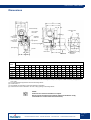
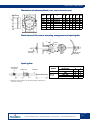
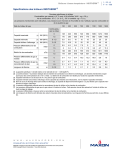
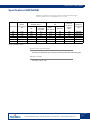
Gas burners - INDITHERM Specifications INDITHERM Maximum capacities and gas pressures required for natural gas Gross heating value = 10.9 kWh/m3 (st), d = 0.6 Blower Burner size motor capacity kW 100 300 600 800 1100 2000 0.25 0.25 0.55 0.75 1.10 2.20 Min. capacity kW Static pressure in combustion chamber mbar (1) kW Gas pressure ∆ P at test connection Pilot + main burner pilot only Gas inlet ∆ P for max. capacity mbar 100 300 570 800 1100 2000 4.1 4.0 10.3 7.4 15.0 15.0 4.3 10.8 17.5 25.3 32.0 50.9 2.9 5.8 10.2 13.0 26.1 34.0 5.6 6.5 12.0 9.6 19.0 17.0 Range of flame length mm 400-600 1000-1200 1400-1600 1500-1700 1800-2200 2500-3000 (1) Max. pressure 1.5 mbar. Blower motor specifications All motors are 3000 RPM, rigid mounted, permanently lubricated, ball-bearing type. Standard voltage 220/380 V - 50 Hz - 3 ph. All data shown on this page are subject to change without notice. MAXON UNITED STATES - MAXON EUROPE - MAXON ASIA - WWW.MAXONCORP.COM E 2.160.3 3/05 Gas burners - INDITHERM Dimensions air filter assembly 4 mounting holes ø13 1/8” air switch connection 1/4” gas pressure test connection G.O.D. adjustable orifice 1/8” 1/4” air pressure test connection sight glasses UV scanner protection spark ignitor gas inlet (1) control motor (2) discharge sleeve AISI 310S 200 mm Size 100 300 600 800 1100 2000 Dimensions in mm (unless stated otherwise) A B (3) C D E (4) F G (5) H J K L M N P R S T U 224 224 308 387 386 451 1" 1 1/4" 1 1/2" 2" 2" 3" 138 138 154 154 154 154 168 195 219 219 219 219 438 437 459 459 605 564 91 90 95 67 132 132 160 210 260 260 311 311 214 264 318 318 375 375 224 222 251 251 360 360 260 259 297 297 424 424 111 111 138 138 165 165 365 365 514 598 597 659 92 113 143 143 170 170 353 353 400 448 448 480 289 289 341 403 403 449 451 449 516 535 630 676 433 433 502 752 752 752 5 5 8 8 8 8 (1) When customer's control motor is used, INDITHERM burner is arranged to accept it, but requires a CB&L assembly, see page<$volnum>.160.7 (2) For high temperature applications include a discharge sleeve. (3) Thread: ISO 7/1. (4) Not certified, but according to motor manufacturer's information. (5) Add minimum 25 mm to dimension “G” when cutting opening for discharge sleeve. NOTE: Dimensions of silencers available on request. Burner can be mounted in any position (subject to limitations set by manufacturer of control motor and UV-scanner). All data shown on this page are subject to change without notice. MAXON UNITED STATES - MAXON EUROPE - MAXON ASIA - WWW.MAXONCORP.COM E 2.160.4 3/05 Gas burners - INDITHERM Dimensions of refractory block (in mm unless stated otherwise ) E B A 22.5 F Burner size A B C D E F G H JØ 100 300 600 800 1100 2000 12 12 12 12 12 12 200 200 200 200 200 200 M10 x 25 M10 x 25 M10 x 25 M10 x 25 M10 x 25 M10 x 25 263 311 363 363 414 414 320 368 420 420 471 471 190 241 292 292 346 346 157 205 257 257 308 308 357 405 457 457 508 508 14 14 14 14 14 14 C 45 J D G H Detail views of UV scanner mounting arrangement and spark ignitor B UV scanner mounting B burner cone gas nozzle section “B-B” spark ignitor assembly Spark ignitor high tension connector locking nut (1) Flame detector insulator with UV scanner X 1/2" NPT Y Spark ignitor assembly n° 025663 Burner size X Y 100 300 600 - 800 1000 - 2000 33 37 31 31 5 5 5 5 (1) standard on burner assembly, to be specified separately if spark ignitor is ordered as a spare part All data shown on this page are subject to change without notice. MAXON UNITED STATES - MAXON EUROPE - MAXON ASIA - WWW.MAXONCORP.COM E 2.160.6 3/05 Gas burners - INDITHERM Assembly numbers and other useful information when ordering (1) Burner assembly n° INDITHERM Type Blower motor capacity kW Arranged for but less connecting bracket and linkage for control motor (2) Items included with burner INDITHERM Spark ignitor Pilot adjustable orifice cock Options Air inlet filter Using UV scanner (3) 100 300 600 800 1100 2000 0.25 0.25 0.55 0.75 1.10 2.20 300666 300667 300668 300669 300670 300671 025663 038009 026072 026072 026073 026075 026075 026076 Connecting bracket and linkage for control motor Motor type BAELZ WBS 375/03 BARBER COLMAN MC, MF, MP FOXBORO P-25 (pneum.) FOXBORO P-50 (pneum.) HONEYWELL 03-8SLO, 01-11SLO (pneum.) HONEYWELL M640A, M940A HONEYWELL M644A, M941, M944 HONEYWELL M940 TA M5 JOHNSON 3D-251 (pneum.) ITT ESM 0,5 E/60 ITT RSM 55 (pneum.) JOUVENEL & CORDIER AZ JOUVENEL & CORDIER AX, AT LANDIS & GYR SQD LANDIS & GYR SQE PENN M80, M81 PHILIPS 2,5 kgm REGEL-und KLIMATECHNIK RK-M (1) (2) (3) (4) (5) (6) (7) (8) Assembly n° 304016 019866 024066 (4) 027104 (5) 020685 022099 019680 (6) 024510 (7) 304022 025187 (8) 304032 304038 304008 304012 304028 304034 019680 304004 304041 Includes protective cover. Order connecting bracket and linkage to match control motor. Not included as part of burner. Specify with B3601-LR and B6301 KY connecting assembly actuator to be less indicating pointer. Specify with B3601-WR and B6301 TY connecting assembly actuator to be less indicating pointer. Specify control motor with 7616 BR crank. For vertical mounting. Add D251-8020 linkage. ORDER EXAMPLE: 1 - no. 300666 INDITHERM 100 burner for natural gas; 220/380 50/3, with 1 - no. 019680 CB&L for HONEYWELL control motor and 1 - no. 026072 air inlet filter. All data shown on this page are subject to change without notice. MAXON UNITED STATES - MAXON EUROPE - MAXON ASIA - WWW.MAXONCORP.COM E 2.160.7 3/05 Gas burners - INDITHERM Specifications BACK PRESSURE: static pressure within combustion affects maximum burner capacity. PILOTING: is accomplished by internally bypassing the built-in gas butterfly valve (which is in the closed position at “LO” fire). The pilot gas is admitted to the gas nozzle via the main gas conduit and is issued from the same gas nozzle ports as the main gas. The pilot is the adjustment means for minimum burner capacity. An interrupted pilot offers no safety advantage but it may result in an increased minimum, as the linkage must be set above “LO” to secure adequate main gas flow for the minimum. LOW FIRE START is essential for burners with a nominal capacity higher than 350 kW. Direct burner start is allowed (without pilot burner) for all capacities below 350 kW. To secure burner turndown characteristics, low fire (“LO”) position must be as low as possible (adjust “LO” position). GAS PRESSURE ADJUSTMENT: outlet of the gas pressure regulator equals: static pressure (or depressure) within combustion chamber gas pressure at burner inlet (see selection table - page 2.160.2.1) pressure drop over butterfly valve (5 mbar for natural gas, 2 mbar for propane) pressure drop over safety valves GAS PIPE-TRAIN: the safety valves should be selected to resist the gas pressure regulator. Their total pressure drop should be not more than 10 mbar (4 mbar if propane). Capacity of gas pressure regulator can be approx. 130% of burner requirements. PROPANE AND BUTANE: all INDITHERM burners are suitable for operation on propane and butane. Specify when placing order. TOWN GAS: INDITHERM can be used with town gas having a high hydrogen content, however this requires a modification. Specify when placing order. FLAME LENGTHS shown are approximate. COMBUSTION AIR PRESSURE SWITCH: a differential connection of switch, blower-to-combustion chamber is recommended. The combustion air pressure switch should be selected to have a set point ranging from 2 to 10 mbar for a static pressure of 0 mbar within the combustion chamber (equivalent to a differential connection). Setpoint to be 2.5 mbar lower than min. pressure measured (at high fire). MEASURING STATIC PRESSURE IN COMBUSTION CHAMBER: if there is no direct pressure test connection with the combustion chamber, proceed as follows: Connect one end of manometer with the gas pressure test connection - the other end being in the ambient air. Start combustion air ventilation. Gas is closed and burner is in low fire position (“LO”); read pressure (positive or negative) indicated on manometer. To adjust air/gas ratio, pressure indicated on manometer is to be added to the value indicated in the burner capacity table. Example: 1. Static pressure in combustion chamber:+1.5 mbar Gas pressure indicated in catalogue:+10 mbar (diff.) Required gas pressure at test connection: All data shown on this page are subject to change without notice. MAXON UNITED STATES - MAXON EUROPE - MAXON ASIA - WWW.MAXONCORP.COM E 2.160.8 3/05 Gas burners - INDITHERM +11.5 mbar 2. Static pressure in combustion chamber:-1 mbar Gas pressure indicated in catalogue:+10 mbar (diff.) Required gas pressure at test connection: +9 mbar Note: to adjust gas and combustion air, make clear distinction between gas and air test connection of burner. In all cases, the second end of the manometer must remain in ambient air. Make sure that back-pressure is always below 1.5 mbar. All data shown on this page are subject to change without notice. MAXON UNITED STATES - MAXON EUROPE - MAXON ASIA - WWW.MAXONCORP.COM E 2.160.9 3/05 Gas burners - INDITHERM Specific installation instructions for Maxon INDITHERM burner systems Instructions provided by the company responsible for the manufacture of a complete system incorporating Maxon burners take precedence over the installation and operating instructions provided by Maxon. If any of the instructions provided by Maxon are in conflict with local codes or regulations, please contact our nearest branch office or representative. Before reading following “installation instructions” please refer to the “general instructions” on burner system installation, piping lay-out, pipe size and manifolding, electrical installation and burner installation. Do not discard packing material until loose items are accounted for. To prevent damage in transit spark ignitor discharge sleeve and linkage (if any) are shipped “loose”. space required for flame rod/scanner removal air supply air pressure switch (option) oven wall 1 air supply B 2 2 3 4 5 space required for spark ignitor removal fuel supply fuel supply Burner mounting Burner may be mounted in any position suitable for automatic control motor and UV-scanner. Cut opening at least 25 mm larger in diameter than discharge sleeve to allow for sleeve expansion.(B) Additional burner support (5) may be required in conjunction with a stiffener plate (6) to support burner weight (50 - 175 kg). Air control motors in particular will often require additional support. 13 mm diameter holes in discharge sleeve flange accept 10 mm stud bolts welded to panels or stiffener. Seal welding of burner flange to stiffener plate at (A) may cause warpage of burner flange and require additional seal material to prevent leakage. All data shown on this page are subject to change without notice. MAXON UNITED STATES - MAXON EUROPE - MAXON ASIA - WWW.MAXONCORP.COM E 2.160.10 3/05 Gas burners - INDITHERM Four lock screws ( 2) permit centering mixing cone within burner body and sleeve. They should be drawn up hand-tight, then backed out 180° to allow for cone expansion. They must be rechecked after start-up and loosened if necessary to prevent deformation of cone. See start-up instruction for details. Tightening can lead to cone distortion and greatly reduced cone and discharge sleeve life. Discharge sleeve (3) must be flush with, or extended beyond interior wall. A viewing port (4) should be provided for flame observation in such a position that burner pilot and main flame can both be seen. Installer must comply with all applicable codes and standards. Observe required space for parts removal. Installation of flame scanner A flame scanner can be applied to an INDITHERM burner for the purpose of flame detection. All data shown on this page are subject to change without notice. MAXON UNITED STATES - MAXON EUROPE - MAXON ASIA - WWW.MAXONCORP.COM E 2.160.11 3/05 Gas burners - INDITHERM Start-up and adjustment instructions Instructions provided by the company or individual responsible for the manufacture and/or installation of a complete system incorporating Maxon burners take precedence over the installation and operating instructions provided by Maxon. If any of the instructions provided by Maxon are in conflict with the local codes or regulations, please contact Maxon before initial start-up of equipment. Before initiating the following start-up and adjustment procedure, it is important that a check be made to verify that all of the equipment associated with and necessary to the operation of the INDITHERM burner system has been installed and piped in accordance with the “General installation instructions”. If the burner system is part of an oven or other heating unit which has been purchased as a complete pre-piped and pre-wired package, it may be assumed that these instructions have already been carried out by the individual or company responsible for the overall installation. All data shown on this page are subject to change without notice. MAXON UNITED STATES - MAXON EUROPE - MAXON ASIA - WWW.MAXONCORP.COM E 2.160.12 3/05 Gas burners - INDITHERM To start-up an INDITHERM burner for the first time Close main gas cock and pilot gas cock. Establish correct blower direction of rotation. Observe direction of rotation of blower motor (rotating towards blower discharge as per arrow on blower housing). The direction in which the motor shaft is rotating can be easily determined by momentarily energizing the motor circuit. As the motor slows to a stop, watch the shaft at the point where it is connected to the impeller. If the impeller turns backwards when 3-phase alternating current is used as the power supply, reverse any two of the leads and recheck for correct rotation. Disconnect automatic control motor. Disconnect wiring between control motor and burner control crank to allow manual handling. Start motor of combustion air fan (with main gas cock still closed). Purge combustion chamber. Start combustion fan and move the burner control crank arm toward “HI” fire position. So that air only will be flowing through burner and combustion chamber, purging any explosive vapours that may have accumulated prior to initial start-up or during a periodic shut-down. When it is certain that the system is completely free of explosive vapours move the burner control crank arm toward “LO” fire position. Length of purge time required will usually be specified by insurance or approval agency having jurisdiction. Bleed air from the fuel supply line. After completion of purging remove the adjusting screw cover from the top of the pilot gas pressure regulator (if applicable) and unscrew adjusting screw completely up to the top (counter clockwise). Make sure that burner gas control valve is in “LO” position. Open main gas cock and pilot gas cock together and press ignition push button. The spark ignitor is energized (as can be seen through the observation port of the burner), the pilot solenoid valve will open to allow gas flow to the burner. While energizing spark ignitor, turn the pilot gas regulator screw in (clockwise) until pilot gas is ignited. Flame should be blue and stable. It may take several seconds before the air is bleeded from the fuel supply line and replaced by gas. The pilot gas regulator should have an outlet pressure of 5-15 mbar. In most of the cases, pilot ignition should take place automatically and stop after a determined period of time. As soon as UV scanner detects pilot flame, the safety circuit will open the pilot solenoid valve and energize the main safety valve which will open to allow main gas flow to the main burner. Remark: should you have questions regarding the operation of the control/safety systems, please contact Maxon. Adjustment of the main gas pressure regulator. Adjust air/gas ratio; the precise adjustment of the main gas pressure regulator, which controls the gas pressure supplied to the burner, will influence combustion efficiency. Make sure that burner control crank is in “LO” fire position. Observe flame presence through observation port at the rear of the burner. Open main gas shut-off valve to ignite main burner. Remove top cover of main pressure regulator and adjust burner inlet pressure as indicated in the selection table (page 2.600.2.1). To obtain correct burner operation we recommend to check burner adjustments by analysing the combustion products. At max. burner capacity the oxygen content in the fumes should be approx. 3%. Slowly move burner control crank toward “HI” fire position. Adjust main gas pressure regulator to provide the desired burner conditions. The required gas pressure under normal operating conditions and the kW capacity are stamped on the burner nameplate. Replace the regulator covers and proceed. Reconnect automatic control linkage. Reconnect linkage and run control motor to its extreme limits of travel. Check that linkage does not bind and that burner firing rate control handle does not go beyond the words “LO” or “HI”. The full range of firing rates from “LO” to “HI” should be used if the rated maximum capacity (see nameplate) and turn-down is desired. If interrupted pilot is used. If pilot is to be interrupted after start-up so flame failure detection operates from All data shown on this page are subject to change without notice. MAXON UNITED STATES - MAXON EUROPE - MAXON ASIA - WWW.MAXONCORP.COM E 2.160.13 3/05 Gas burners - INDITHERM main flame only, then it may be necessary to advance the pointer on the burner control arm from “LO” to the first casting mark, towards the “HI” fire position. Under normal operating conditions this will open the gas butterfly valve sufficiently to produce a minimum main flame, independent of the pilot flame. This is accomplished by adjustment of the linkage between the control operator and the burner crank. It will be necessary to move the toggle on the control motor arm in towards the motor shaft to reduce the radius slightly so as to prevent the burner control arm from moving past the casting “HI” mark. Operating instructions The operating instructions below are provided only as a guide-line and are not intended to replace those provided by the manufacturer of a complete system of which the INDITHERM burner is only a part. Where applicable, instructions provided by the system's manufacturer shall take precedence. To start (automatically) Open main gas and pilot gas cocks. Push start or pilot button. To start (manually) Make sure that safety shut-off valve, main gas and pilot gas cocks are closed. Make sure the burner firing rate control handle is at predetermined low fire position. Start air circulating and exhaust fans. Energize system control panel, if applicable. Start burner blower motor. Open main gas and pilot gas cocks. Press start button (pilot solenoid valve should open to allow pilot ignition). Main gas valve will open (only when all safety circuits are complete). To stop (automatically or manually) Close main gas and pilot gas cocks. Burner continues operating until flame extinguishes (can be observed through observation port at the rear of the burner). Safety shut-off valve and solenoid valve should automatically close. De-energize system control panel as well as the burner blower motor. All data shown on this page are subject to change without notice. MAXON UNITED STATES - MAXON EUROPE - MAXON ASIA - WWW.MAXONCORP.COM E 2.160.14 3/05