1
Operator's
Manual
CRRFrSMRH
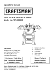
10 iN. PORTABLE TABLE SAW
Model No. 137.415030
C
US
CAUTION"
Before using this Table Saw,
read this manual and follow
all its Safety Rules and
Operating Instructions
Customer
Help Line
For Technical
Support
1-800-843-1682
•
•
•
•
0
Safety Instructions
Assembly
Operation
Maintenance
Parts List
Sears Parts &
Repair Center
1-888-331-4569
Sears Brands Management
Corporation
Hoffman
Estates,
See the full line of Craftsman ® products at craftsman.corn
Click on the Craftsman Club ® link and join today!
Part No. 137415030001
IL 60179
USA
Printed in China
SECTION
PAGE
Warranty
................................................................................................................
Product Specifications
...........................................................................................
Symbols ..................................................................................................................
Power Tool Safety ..................................................................................................
Table Saw Safety ...................................................................................................
Electrical
Requirements
and Safety .......................................................................
Accessories
and Attachments
................................................................................
2
3
4
5
8
12
14
Tools Needed for Assembly
...................................................................................
Carton Contents
....................................................................................................
Know Your Table Saw ............................................................................................
14
15
17
Glossary of Terms ..................................................................................................
Assembly
...............................................................................................................
Adjustments
...........................................................................................................
Operation
...............................................................................................................
Maintenance
..........................................................................................................
18
20
29
35
45
Troubleshooting
Guide ..........................................................................................
Parts List ................................................................................................................
48
51
Repair
56
Protection
Agreement
.................................................................................
CRAFTSMAN
ONE YEAR LIMITED WARRANTY
FOR ONE YEAR from the date of purchase, this product is warranted against defects in
material or workmanship.
With proof of purchase, a defective product will receive free repair
or replacement at option of seller. For warranty coverage details or to obtain free repair or
replacement,
visit the web page: www.craftsman.com/warranty
This warranty does not cover the blade, which is an expendable part that can wear out from
normal use within the warranty period. This ONE YEAR warranty is void if this product is
ever used while providing commercial services or if rented to another person. For 90 DAY
commercial and rental use terms, see the Craftsman warranty web page. This warranty gives
you specific legal rights, and you may also have other rights which vary from state to state.
Sears Brands
Management
Corporation,
Hoffman
Estates, IL 60179
CALIFORNIA
PROPOSITION
65
WARNING
1
Some dust created by power sanding, sawing, grinding, drilling and other construction
activities contains chemicals known to the state of California to cause cancer, birth defects
or other reproductive
harm. Some examples of these chemicals are:
® Lead from lead-based paints,
® Crystalline silica from bricks, cement and other masonry
products, and
® Arsenic and chromium from chemically treated lumber.
Your risk from these exposures
varies, depending
on how often you do this type of work.
To reduce your exposure
to these chemicals:
work in a well ventilated
area, and work
with approved
safety equipment,
such as those dust masks that are specially
designed
to
filter out microscopic
particles. Avoid prolonged contact with dust from power sanding,
sawing, grinding,
drilling, and other construction
activities.
Wear protective clothing
and
wash exposed
areas with soap and water. Allowing
dust to get into your mouth, eyes, or
lay on the skin may promote absorption
of harmful
chemicals.
2 .........................................................................................................
2014/01
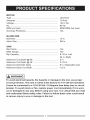
MOTOR
Type ..............................................................................
Amperes .......................................................................
Voltage .........................................................................
Hz .................................................................................
Universal
15 Amp
120 V AC
60 Hz
RPM (no load) .............................................................
Overload Protection .....................................................
5000 RPM (No load)
Yes
BLADE SiZE
Diameter ......................................................................
Arbor Size ....................................................................
10 in.
5/8 in.
SAW
Rip Fence ......................................................................
Miter Gauge ..................................................................
Rip Capacity ................................................................
Maximum
Maximum
Maximum
Maximum
Cut Depth @ 90° .........................................
Cut Depth @ 45 ° .........................................
Diameter Dado ............................................
Dado Cut Width ...........................................
Yes
Yes
8-1/2 in. Left
24 in. Right
3 in.
2-1/2 in.
6 in. (Stackable only)
1/2 in.
WARNING
1
To avoid electrical hazards, fire hazards or damage to the tool, use proper
circuit protection. This tool is wired at the factory for 110=120 Volt operation.
it must be connected to a 110-120 Volt/15 Ampere time delay fuse or circuit
breaker. To avoid shock or fire, replace power cord immediately if it is worn,
cut or damaged in any way. Before using your tool, it is critical that you read
and understand these safety rules. Failure to follow these rules could result
in serious
injury to you or damage to the tool.
WARNINGiCONS
Your power tool and its Operator's
(a picture symbol intended to alert
a potentially hazardous condition).
symbols will help you operate your
some of the symbols you may see.
Manual may contain "WARNING iCONS"
you to, and/or instruct you how to avoid,
Understanding
and heeding these
tool better and safer. Shown below are
SAFETY ALERT: Precautions that involve your safety.
®
PROHIBITION
WEAR EYE PROTECTION:
glasses with side shields,
Always wear safety goggles or safety
WEAR RESPIRATORY AND HEARING PROTECTION: Always wear
respiratory and hearing protection.
READ AND UNDERSTAND INSTRUCTION MANUAL: To reduce
the risk of injury, user and all bystanders must read and understand
instruction manual before using this product.
KEEP HANDS AWAY FROM BLADE: Failure to kee.p your hands
away from the blade will result in serious personal injury.
SUPPORT AND CLAMP WORK
DANGER: indicates an imminently hazardous situation
IA DA.GER
Mwhich,
if not avoided, will result in death or serious injury.
i_
WARNING
1 WARNING:
indicates a potentially hazardous situation
which, if not avoided, could result in death or serious injury.
CAUTION: indicates a potentially hazardous situation
IA cAuTIO.1 which,
if not avoided, may result in minor or moderate
[ CAUTION
I
injury,
CAUTION: used without the safety alert symbol indicates
a potentially hazardous situation which, if not avoided, may
result in property damage.
GENERAL SAFETY iNSTRUCTiONS
BEFORE USING THiS POWER TOOL
Safety is a combination of common
sense, staying alert and knowing how
to use your power tool,
[,_WARNING
cause serious
that could
injury, do not plug
the tool in until you have read
and understood the following.
o Read all instructions
before
operating product. Failure to
follow all instructions
listed
below may result in electric
shock, fire and/or serious injury.
,
READ and become familiar
with the entire Operator's
Manual. LEARN the tool's
application, limitations and possible
hazards.
,
KEEP GUARDS iN PLACE and in
working order.
,
REMOVE ADJUSTING KEYS
AND WRENCHES. Form the habit
of checking to see that keys and
adjusting wrenches are removed
from the tool before turning ON.
,
DO NOT USE iN DANGEROUS
ENVIRONMENTS. Do not use
power tools in damp locations, or
expose them to rain or snow. Keep
work area well lit.
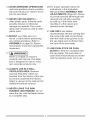
6. KEEP CHILDREN AWAY. All
1
o To avoid mistakes
,
KEEP WORK AREA CLEAN.
Cluttered areas and benches
invite accidents.
visitors and bystanders should be
kept a safe distance from work area.
7. MAKE WORKSHOP CHILD PROOF
with padlocks, master switches or by
removing starter keys.
8. DO NOT FORCE THE TOOL. It will
do the job better and safer at the
rate for which it was designed.
9. USE THE RIGHT TOOL. Do not
force the tool or an attachment to do
a job for which it was not designed.
10.USE PROPER EXTENSION
CORDS. Make sure your extension
cord is in good condition. When
using an extension cord, be sure to
use the one heavy enough to carry
the current that the product will
draw. An undersized cord will result
in a drop in line voltage and in loss
of power which will cause the tool
overheat. The table on page 13
shows the proper wire gauge size
usage to each extension cord length
and ampere rating. If in doubt, use
the next heavier gauge. The smaller
the gauge number, the heavier
the cord.
11.WEARPROPER
APPAREL.Do
notwearlooseclothing,gloves,
neckties,rings,braceletsor other
jewelrywhichmaygetcaughtin
movingparts.Nonslipfootwearis
recommended.
Wearprotective
hair
coveringtocontainlonghair.
12._,
ALWAYS
WEAREYE
PROTECTION.
Anypower
toolcanthrowforeign
objectsintotheeyes and could
cause permanent eye damage.
ALWAYS wear Safety Goggles (not
glasses) that comply with ANSI
Safety standard Z87.1. Everyday
eyeglasses have only impactresistant lenses. They ARE NOT
safety glasses. Safety Goggles are
available at Sears. NOTE: Glasses
or goggles not in compliance with
ANSI Z87.1 could seriously injure
you when they break.
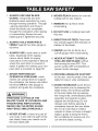
13.
WEAR A FACE MASK
OR DUST MASK. Sawing
operation produces dust.
14.
SECURE WORK. Use
clamps or a vice to hold work
when practical. It is safer
than using your hand and
it frees both hands to operate
the tool.
15. DISCONNECT TOOLS FROM
POWER SOURCE before servicing,
and when changing accessories
such as blades, bits and cutters.
16.REDUCE THE RISK OF
UNINTENTIONAL STARTING.
Make sure switch is in the OFF
position before plugging the tool in.
17.USE RECOMMENDED
ACCESSORIES. Consult
this Operator's Manual for
recommended accessories.
The use of improper accessories
may cause risk of injury to yourself
or others.
18.NEVER STAND ON THE TOOL.
Serious injury could occur if the
tool is tipped or if the cutting tool is
unintentionally contacted.
19.CHECK FOR DAMAGED PARTS.
Before further use of the tool, a
guard or other part that is damaged
should be carefully checked to
determine that it will operate
properly and perform its intended
function - check for alignment of
moving parts, binding of moving
parts, breakage of parts, mounting
and any other conditions that may
affect its operation. A guard or other
part that is damaged should be
properly repaired or replaced.
20.NEVER LEAVE THE TOOL
RUNNING UNATTENDED. TURN
THE POWER "OFF". Do not walk
away from a running tool until the
blade comes to a complete stop
and the tool is unplugged from the
power source.
21.DONOTOVERREACH.
Keep
properfootingandbalanceatall
times.NEVERreachacrossthe
pathofthecuttingbladewhiletoolis
inoperation.
22.MAINTAIN
TOOLSWITHCARE.
Keeptoolssharpandcleanforbest
andsafestperformance.
Follow
instructions
forlubricatingand
changingaccessories.
23.DONOTusepowertoolinpresence
offlammableliquidsor gases.
24.DONOToperatethetoolifyouare
undertheinfluence
ofanydrugs,
alcoholor medication
thatcould
affectyourabilityto usethetool
properly,
25"I,_
WARNING
L_
Dust generated
from certa n
materials can be hazardous to your
health. Always operate saw in wellventilated area and provide for
proper dust removal.
26[,_k
DANGER
I Pe°plewith
electronic
devices, such as pacemakers,
should consult their physician(s)
before using this product. Operation
of electrical equipment in close
proximity to a heart pacemaker
could cause interference or failure
of the pacemaker.
27.
WEAR HEARING
PROTECTION to reduce the
risk of induced hearing loss.
7
1. ALWAYS USE SAW BLADE
GUARD, riving knife and antikickback pawls assembly for every
through-sawing operation. Through
-sawing operations are those in
which the blade cuts completely
through the workpiece when ripping
or crosscutting. Always be sure
blade guard is tightened securely.
2. ALWAYS HOLD WORKPIECE
FIRMLY against the miter gauge or
rip fence.
3. ALWAYS USE a push stick or push
block, especially when ripping
narrow stock. Refer to ripping
instructions in this Operator's Manual
where the push stick is covered in
detail. A pattern for making your own
push stick is included on page 50.
4. NEVER PERFORM ANY
OPERATION FREEHAND, which
means can using hands to support
the workpiece, but always use either
the fence OR the miter gauge to
position and guide the workpiece.
WARNING
i
FREEHAND CUTTING IS THE
MAJOR CAUSE OF KICKBACK AND
FINGER/HAND AMPUTATIONS.
NEVER USE THE MITER GAUGE
AND FENCE SIMULTANEOUSLY.
5. NEVER STAND or have any part of
your body in line with the path of the
saw blade. Keep your hands out of
the saw blade path.
6. NEVER REACH behind or over the
cutting tool for any reason.
7. REMOVE the rip fence when
crosscutting.
8. DO NOT USE a molding head with
this saw.
9. DIRECTION OF FEED. Feed work
into a blade against the direction of
rotation of the blade.
10.NEVER use the rip fence as a
cut-off gauge when crosscutting.
11.NEVER ATTEMPT TO FREE A
STALLED SAW BLADE without
first turning the saw OFF. Turn
power switch OFF immediately to
prevent motor damage.
12.PROVIDE ADEQUATE SUPPORT
to the rear and the sides of the saw
table for long or wide workpieces.
1&AVOID KICKBACKS (work thrown
back towards you) by keeping the
blade sharp, the rip fence parallel
to the saw blade and by keeping
the riving knife, anti-kickback pawls
assembly and guards in place,
aligned and functioning. Do not
release work before passing it
completely beyond the saw blade.
Do not rip work that is twisted,
warped or does not have a straight
edge to guide it along the fence.
Do not attempt to reverse out of a
cut with the blade running.
14.AVOID
AWKWARD
OPERATIONS
and hand positions where a sudden
slip could cause your hand to move
into the saw blade,
15.NEVER USE SOLVENTS to
clean plastic parts. Solvents could
possibly dissolve or otherwise
damage the material. Only a soft
damp cloth should be used to clean
plastic parts.
16.MOUNT your table saw on a
bench or stand before performing
any cutting operations. Refer to
ASSEMBLY on page 20. Secure
tool properly to prevent unexpected
movement.
17.1,_
WARNING
1
Never cut metals or masonry
products with this tool. This table
saw is designed for use on wood
and wood-like products only.
18.ALWAYS USE iN A WELLVENTILATED AREA. Remove
sawdust frequently. Clean out
sawdust from the interior of the saw
to prevent a potential fire hazard.
Attach a vacuum to the dust port for
additional sawdust removal.
19.NEVER LEAVE THE SAW
RUNNING UNATTENDED. Do not
leave the saw until the blade comes
to a complete stop.
20.For proper operation follow the
instructions in this Instruction
Manual entitled ASSEMBLY AND
ADJUSTMENTS (Page 20). Failure
to provide sawdust fall-through and
removal hole will allow sawdust
to build up in the motor area
resulting in a fire hazard and
potential motor damage.
21 .USE ONLY saw blades
recommended with the warning that
the riving knife shall not be thicker
than the width of the groove cut by
the saw blade and not thinner than
the body of the saw blade.
22.USE PUSH-STICK OR PUSH
BLOCK to feed the workpiece past
the saw blade. The push-stick or
push block should always be stored
with the machine when not in use.
SAWBLADEGUARD
ANTI-KICKBACK
RiViNG KNIFE
ASSEMBLY,
ASSEMBLY AND
Your table saw is equipped with a
blade guard assembly, anti-kickback
assembly and riving knife that covers
the blade and reduces the possibility
of accidental blade contact. The riving
knife is a flat plate that fits into the cut
made by the saw blade and effectively
fights kickback by lessening the
tendency of the blade to bind in the cut.
The blade guard assembly and antikickback assembly can only be used
when making through cuts that sever
the wood. When making rabbets and
other cuts that make non through cuts,
the blade guard assembly and antikickback assembly must be removed
and riving knife lowered to the
non through cut position marked on the
riving knife. Two anti=kickback pawls are
located on the sides of the riving knife
that allow the wood to pass through the
blade in the cutting direction but reduce
the possibility of the material being
thrown backwards toward the operator.
Use all components of the guarding
system (blade guard assembly, riving
knife and anti-kickback assembly) for
every operation for which they can
be used including all through cutting.
If you elect not to use any of these
components for a particular application
exercise additional caution regarding
control of the workpiece, the use of
push sticks, the position of your hands
relative to the blade, the use of safety
glasses, the means to avoid kickback
and all other warnings contained in this
manual and on the saw itself. Replace
the guarding systems as soon as you
return to thru-cutting operations. Keep
the guard assembly in working order.
KICKBACKS
KICKBACKS: Kickbacks can cause
serious injury. A kickback occurs when
a part of the workpiece binds between
the saw blade and the rip fence, or
other fixed object, and rises from the
table and is thrown toward the operator.
Kickbacks can be avoided by attention
to the following conditions.
How to Avoid Kickbacks
and Protect
Yourself from Possible Injury:
a. Be certain that the rip fence is
parallel to the saw blade.
b. Do not rip by applying the feed force
to the section of the workpiece that
will become the cut-off (free) piece.
Feed force when ripping should
always be applied between the saw
blade and the fence; use a push
stick for narrow work, 6 in. (152
mm) wide or less.
c. Keep saw blade guard assembly,
riving knife and anti-kickback
assembly in place and operating
properly. If anti-kickback assembly
is not operational, return your unit
to the nearest authorized service
center for repair. The riving knife
must be in alignment with the saw
blade and the anti-kickback pawls
assembly must stop a kickback
onceit hasstarted.Checktheir
actionbeforerippingby pushing
thewoodundertheanti-kickback
assembly.
Theteethmustprevent
thewoodfrombeingpulledtoward
thefrontofthesaw.
d. Plasticandcomposite(like
hardboard)
materialsmaybecuton
yoursaw.However,
sincetheseare
usuallyquitehardandslippery,the
anti-kickback
pawlsmaynotstopa
kickback.
Therefore,
beespecially
attentivetofollowingpropersetup
andcuttingprocedures
forripping.
e. Usesawbladeguardassembly,
anti-kickback
pawlsassembly
and
rivingknifeforeveryoperation
for
whichit canbeused,includingall
through-sawing.
f. Pushtheworkpiecepastthesaw
bladepriorto release.
g. Neverripa workpiece
thatis
twistedor warped,or doesnot
havea straightedgetoguidealong
thefence.
h. Neversawa largeworkpiecethat
cannotbecontrolled.
i. Neverusethefenceasa guideor
lengthstopwhencrosscutting.
j. Neversawaworkpiece
withloose
knots,flaws,nailsor otherforeign
objects.
k. Neverripa workpiece
shorterthan
10in.(254mm).
I. NEVERusea dullblade- replace
or haveresharpened.
m.NEVERusea ripfenceandmiter
gaugetogether.
n. Keephandsoutofsawblade.
POWERSUPPLY AND MOTOR
SPECiFiCATiONS
i,AWARNING
1
To avoid electrical hazards, fire
hazards, or damage to the tool, use
proper circuit protection. Use a
seperate electrical circuit for your
tool. Your table saw is wired at the
factory for 120 V operation. Connect
to a 120 V, 15Amp circuit and use
a 15 Amp time delay fuse or circuit
breaker. To avoid shock or fire,
if power cord is worn, cut, or
damaged in any way, have it
replaced immediately.
GROUNDING
INSTRUCTIONS
,_ WARNING
I
This tool must be grounded while
in use to protect the operator from
electrical shock.
iN THE EVENT OF A MALFUNCTION
OR BREAKDOWN, grounding provides
a path of least resistance for electric
currents and reduces the risk of electric
shock. This tool is equipped with an
electrical cord that has an equipment
grounding conductor and a grounding
plug. The plug must be plugged into
a matching receptacle that is properly
installed and grounded in accordance
with all local codes and ordinances.
DO NOT MODIFY THE PLUG
PROVIDED. If it will not fit the
receptacle, have the proper receptacle
installed by a qualified electrician.
IMPROPER CONNECTION
of the
equipment grounding conductor can
result in risk of electric shock. The
conductor with the green insulation
(with or without yellow stripes) is the
equipment grounding conductor. If
repair or replacement of the electrical
cord or plug is necessary, do not
connect the equipment grounding
conductor to a live terminal.
CHECK with a qualified electrician or
service person if you do not completely
understand the grounding instructions,
or if you are not certain the tool is
properly grounded.
USE only 3-wire extension cords
that have three=pronged grounding
plugs with three-pole receptacles
that accept the tool's plug. Repair
or replace damaged or worn cords
immediately.
Use a separate electrical circuit for
your tool. This circuit must not be less
than # 14 wire and should be protected
with a 15 Amp time delay fuse. Before
connecting the motor to the power
line, make sure the switch is in the
off position and the electric current is
rated the same as the current stamped
on the motor nameplate. Running at a
lower voltage will damage the motor.
overheating
andburningoutofthe
motor.Thetablebelowshowsthe
correctsizeto usedepending
oncord
lengthandnameplate
ampererating.If
indoubt,usethenextheaviergauge.
Thesmallerthegaugenumber,
the
heavierthecord.
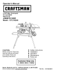
The adapter (Fig. 2) has a grounding
lug extending from it that MUST be
connected to a permanent earth
ground, such as a properly grounded
receptacle box.
l,_
CAUTION
l
In all cases, make certain the
GUIDELINES FOR EXTENSION
CORDS
Make sure your extension cord is
properly wired and in good condition.
Always replace a damaged extension
cord or have it repaired by a qualified
technician before using it. Protect your
extension cords from sharp objects,
excessive heat and damp or wet areas.
receptacle is properly grounded. If
you are not sure, have a qualified
electrician check the receptacle.
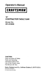
Fig. 1
Three-Pronged Plug
(When usng 120 volts only)
Ampere Rating
MoreThan
Not More Than
Total length of Cord
25ft. 50ft. 100ft. 150 ft.
7.62
15.24
30.48
45.72
m
Three-Pronged Receptacle
AWG- American Wire Gauge
18
16
16
14
0
6
6
10
18
16
14
12
10
12
16
16
14
12
,_ WARNING
This tool is for indoor use only. Do
not expose to rain or use in damp
locations.
This tool is intended for use on a
circuit that has a receptacle like the
one illustrated in Fig. 1. Fig. 1 shows
a three-pronged electrical plug and
receptacle that has a grounding
conductor. If a properly grounded
receptacle is not available, an adapter
(Fig. 2) can be used to temporarily
connect this plug to a two-contact
grounded receptacle.
Fig. 2
Grounding Lug
/ l_-[I
Make sure this
_&_-!,_ ! _kis
connected
_--_:/__"
II to a known
_.J_
"
Adapter
_--_
Two-Pronged
Receptacle
RECOMMENDED
ACCESSORIES
SUPPLIED
NOT SUPPLIED
iA WARNING
1
Visit your Sears Hardware
Department or see the
Craftsman Power and Hand Tools
Catalog to purchase recommended
accessories for this power tool.
308K DADO iNSERT PLATE
iA WARNING
1
To avoid the risk of personal injury:
o Do not use adjustable (wobble)
type dadoes or carbide tipped
dado blades.
o Only use stackable dadoes.
o Maximum dado width is 1/2 in.
o Do not use a dado with a diameter
larger than 6 in.
o Do not use molding head set with
this saw.
o Do not modify this power
tool or use accessories not
recommended by Sears.
Box-end
wrench
Flat bladed
screwdriver
Phillips screwdriver
Open-end
wrench
[!
!!
!!
!!
!!
!!
]
Straight edge
4 mm hex
wrench
Adjustable wrench
and/or 5 mm, 8 mm,
10 mm, 13 mm, and
17 mm wrench
Combination square
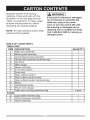
[a, WARNING]
Separateallpartsfrompacking
materials.
Checkeachpartwiththe
illustration
onthenextpageandthe
"Tableof LooseParts"tomakecertain
allitemsareaccounted
for,before
discardinganypackingmaterial.
NOTE:Tomakeassemblyeasier,keep
contentsofboxtogether.
If any part is missing or damaged,
do not attempt to assemble the
table saw, plug in the power
cord, or turn the switch ON until
the missing or damaged part is
obtained and is installed correctly.
Call 1-800=843=1682 for missing or
damaged parts.
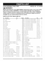
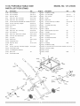
TABLE OF LOOSE PARTS
TABLE SAW
ITEM
DESCRIPTION
QUANTITY
A
Table saw assembly
1
B
C
D
E
F
G
H
I
Blade guard assembly
Anti-kickback pawls assembly
Riving knife assembly hardware bag
Rip fence
Miter gauge
Blade wrenches
4 mm hex wrench
Push stick
1
1
1
1
1
2
1
1
J
K
L
M
N
Rear outfeed support
Rear outfeed support tubes
Rear outfeed support hardware bag
Blade
Handwheel handle
1
2
1
1
1
O
Power cord storage
P
Table saw mounting hardware bag
STAND
Q
R
S
Leg handle hardware bag
Wheel hardware assembly
Stand assembly
1
4 each
1
1
1
15
q
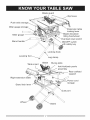
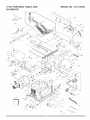
UNPACKING
YOUR TABLE SAW
A
E
F
J
K
q:__
R
D
G
H
L
0
/_
C
B
M
P
Q
o
S
Bladeguard
fence
Pushstickstorage
Mitergaugestorage
table
lockinglever
Bladeelevation/
tiltinghandwheel
Overloadresetswitch
ON/OFFswitch
withsafetykey
Mitergauge
Standhandle
Lockinghook
Leveling
Tableinsert
Legclamp
Blade Rivingknife
Anti-kickback
pawls
assembly
Rearoutfeed
support
Rightextension
table
Powercord
storage
Standlocklever
Dustport
Wheel
Stand
ANTI-KICKBACK
PAWLS
ASSEMBLY
- Prevents the workpiece from being
kicked upward or back toward the front
of the table saw by the spinning blade.
ARBOR - The shaft on which the blade
or dado is mounted.
FREEHAND - Performing a cut without
using a rip fence, miter gauge, hold
down or other proper device to prevent
the workpiece from twisting during the
cutting operation.
GUM - A sticky sap from wood
products.
BEVEL CUT -An angle cut made
through the face of the workpiece.
HEEL - Misalignment of the blade.
BLADE BEVEL SCALE - Measures
JAMB NUT - Nut used to lock another
the angle the blade is tilted when set
for a bevel cut.
nut in place on a threaded rod or bolt.
BLADE ELEVATION/TILTING
removed by the blade cut.
HANDWHEEL
- Raises and lowers
the blade or tilts the blade to angle
between 0° and 45 ° for bevel cuts.
BLADE GUARD - Clear plastic cover
that positions itself over the blade while
cutting.
COMPOUND CUT - A simultaneous
bevel and miter cut.
CROSSCUT - A cut made across the
width of the workpiece.
KERF - The amount of material
KICKBACK-
Occurs when the saw
blade binds in the cut and violently
thrusts the workpiece back toward
the operator.
MITER CUT- An angle cut made
across the width of the workpiece.
MITER GAUGE -A guide used for
crosscutting operations that slides
in the table top channels (grooves)
located on either side of the blade.
It helps make accurate straight or
angle crosscuts.
DADO - Special cutting blades that are
used to cut grooves in a workpiece.
NON-THROUGH
FEATHERBOARD
to any cut that does not completely cut
through the workpiece.
- When ripping
a workpiece on your table saw, this
keeps it firmly and safely against the
rip fence. It also helps prevent chatter,
gouging, and dangerous kickback.
SAWING - Refers
OVERLOAD
RESETSWITCHProtectsthemotorif itoverloads
during
operation,providesa waytorestartthe
saw.
PUSHSTICK- Usedto push
workpieces
whenperforming
ripping
operations.
SAW BLADE PATH - The area of the
workpiece or table top directly in line
with the travel of the blade or the part
of the workpiece that will be cut.
SET - The distance between two saw
blade tips, bent outward in opposite
directions to each other. The further
apart the tips are, the greater the set.
PUSHBLOCK- Usedforripping
operation
whentheworkpiece
istoo
narrowto usea pushstick.Alwaysuse
a pushblockforripwidthslessthan2 in.
(50.8mm).
TABLE INSERT - Insert that is
removed from the table to install /
remove blades. When dado cutting, a
dado insert plate must be used.
RESAWING
- Flippingmaterialto
makea cutthesawisnotcapableof
makinginonepass.
THROUGH SAWING - Making a cut
i,A WARNING
WORKPIECE
i
completely through the length or width
of a workpiece.
Do not resaw material with this saw.
- Material to be cut.
Saw blade path
Leading
REVOLUTIONS PER MINUTE (RPM)
- The number of turns completed by a
spinning object in one minute.
RIP FENCE -A guide used for rip
cutting which allows the workpiece to
cut straight.
RIPPING - Cutting with the grain of
the wood or along the length of the
workpiece.
RIVING KNIFE-A metal piece of the
guard assembly located behind and
in-line with the blade. Slightly thinner
than the saw blade, it helps keep the
kerr open and prevents kickback.
Surface
edge
of
Workpiece
workpiece
NOTE: Blade guard assembly is
removed for purposes of illustration only.
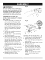
,_k WARNING
i
Fig. A
For your safety, never connect plug
to power source receptacle until all
assembly and adjustment steps are
complete, and you have read and
understood the safety instructions.
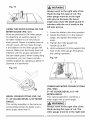
ASSEMBLING THE ROLLER
WHEELS AND HANDLES TO STAND
(FIG. A, B, C)
1. Remove the bolts (2), washers (3)
and nuts (4) from the stand tube.
Insert one leg handle (1)into one
left stand tube and align the holes
on the handle and tube. Use two
Fig. B
bolts (2), two washers (3) and two
nuts (4) to secure the leg handle.
(Fig. A)
2. Tighten with a phillips screwdriver
and 10 mm wrench.
3. Repeat steps 1 - 2 for assembling
the other leg handle.
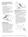
4. Attach one wheel (5) to the outer
side of one right stand leg using the
hex bolt (6), the sleeve (7), two flat
washers (8) and the nut (9). (Fig. B)
NOTE: Verify that the side of the
wheel that has the concavities (10)
is facing toward the stand as shown
in Fig. B.
5. Tighten using two 17 mm wrenches
for the nut and bolt.
NOTE: Do not overtighten. Doing so
will not allow the wheels to turn.
6. Repeat the steps 4 - 5 for
assembling the other wheel.
6
7
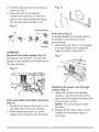
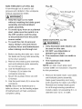
SETTING UP THE STAND (FIG. C, D)
1. Lift the stand to its upright position.
2. Raise leg set (1) all the way up.
Then, lower the stand until leg set (1)
rests on floor.
3. Release the locking hook (2) from
the stop screw (3).
4. Step on the bottom right stand
bar (4) for leverage, grasp right
side of stand frame (7) with both
hands and pull stand up to the
highest position.
NOTE: You should hear a "click"
sound when the stand locks
in place.
.
Check to be sure the stand lock
lever (5) is in the slot of the cover
plate (6). (Fig. D)
NOTE: Do not overtighten the four
bolts as this may cause damage to
the base of the saw.
Fig. C
Fig. E
1
-3
\
3
J
9
.
4
Fig. D
stand lock lever
release direction
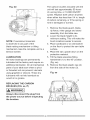
Place the stand on a level surface
and adjust the leveling foot (6)
located on the left front stand leg.
Adjust until all legs are contacting
the floor and are at a similar angle
to the floor.
NOTE: Before using the saw, verify
that the table saw is securely locked
in position.
FOLDING THE STAND FOR
TRANSPORT OR STORAGE
ASSEMBLING
TABLE SAW TO
STAND (FIG. E)
1. Lift the saw body (1) and place
on the stand (2), aligning the four
mounting holds (3) on the saw base
with the four threaded mounting
holes on the top plate of stand.
2. Attach the table saw to the stand
with four hex head bolts (4) and
washers (5).
3. Tighten all mounting bolts with a
13 mm wrench.
(FIG. C, D, F)
1. Lift slightly the right side of table
saw (8 - Fig. F), raise the cover
plate (6) on the right side of stand,
pull the stand lock lever (5) to the
right as the release direction, and
then move the saw slowly close to
the wheel. (Fig. D)
2. Rotate the hook (2) to the stop
screw (3) to secure the legs of the
stand in position. (Fig. C)
3. Rest the right side of the saw onto
the floor.
4. Fold the leg set (1) close to the
base until the leg clamp (9) holds
the right side leg. (Fig. C)
5. Foldthestandslowlydownward
as
shownin Fig.F.
6. Movethesawtothedesired
locationforoperation
or storethe
sawin a dryenvironment
byusing
the leftsidestandhandles(10).
Fig.F
Transporti
ng
8
_.
_,10->_
Folding
STORAGE
Ripfenceandmitergauge(Fig.G)
Storagefortheripfence(1)andmiter
gauge(2)arelocatedontheleftsideof
thesawhousing.
Fig. H
1
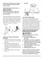
Push stick (Fig. I)
A storage holder for the push stick (1)
is located on the left side of the
saw housing.
1. Store the push stick (1) by hanging
it on the holders (2) through the
holes (3)of the push stick (1).
Fig. I
Fig.G
2
Extra saw blade and blade wrenches
(Fig. H)
1. Loosen and remove the knob (1) on
the right side of the saw housing.
2. Place blade wrenches (2), extra
blades (not included) onto the arbor.
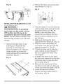
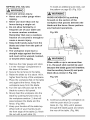
Installing the power cord storage
clamps (Fig. J)
1. Attach the power cord storage
clamp (1) into the hole set on the
rear side of the table saw base with
screw (2) and nut (3).
NOTE: The nut is placed inside
the base.
2. Repeat for the other clamp, to be
located on the bottom right on
saw base.
Fig.J
iNSTALLiNG
THEREAROUTFEED
SUPPORT
(FIG.L, M)
1. Insert the two rear outfeed support
tubes (2) into the rear outfeed
support (1). (Fig. L)
NOTE: They must be inserted into
the back of the extension with the
Powercord (Fig.J-l)
Wrapthe powercord(1)asshown.Do
notwrapthepowercordaroundthe
dustport(2).
Fig.J-I
dimple end so that the bar will hold
the extension in place.
2. Snap two black plastic stops (3)
over the two rear outfeed support
tubes (2). Make sure the locating
pin in the black plastic stops fits into
the matching hole in the support
tube. This will "lock" the tube into
the support. (Fig. L)
NOTE: The plastic stops (3) must
be installed underneath the rear
outfeed support tubes (2).
Fig. L
2
1
INSTALMNG
THEHANDWHEEL
HANDLE(FIG.K)
NOTE:UP-DOWN
is printedonthis
handwheel.
1. Threadthehandwheel
handle(1)
intothehandwheel
hole(2),and
thentighten.
end
1
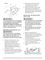
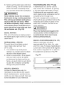
3. Insert the rear outfeed support
tubes (2) into the two holes in the
rear of the saw table, and into the
support tube brackets under the
table. Position the rear outfeed
support so that the instruction labels
are facing up. (Fig. M)
4. Tighten one rear outfeed support
stop screw (4) on the end of the
left rear outfeed support tubes (2).
Verify that the screw is fully inserted
into the corresponding hole in the
support tube. (Fig. M)
Fig.M
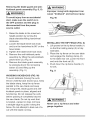
.
2
Remove the arbor nut (3) and outer
blade flange (4). (Fig. O)
Fig. 0
iNSTALLiNG THE BLADE (FIG. N, O, P)
lA WARNING
l
To avoid injury from an accidental
start, make sure the switch is in the
OFF position and the plug is not
connected to the power source outlet.
NOTE: The saw blade is packed in the
blade storage located on the right side
of base.
.
Remove the table insert (1) by
inserting your finger into the
opening (2) and pulling up.
Raise the blade to the maximum
height position by turning the
blade elevation/tilting handwheel
clockwise. (Fig. N)
Fig. N
1
2
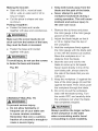
3. Place the blade (7) onto the arbor (5)
with the blade teeth pointing forward
to the front of the saw. (Fig. P)
NOTE: Leave the plastic strip
around the saw blade at this time.
Remove before using the saw for
the first time.
4. Make sure the blade fits flush
against the inner flange (6). (Fig. O)
5. Clean the outer blade flange (4)
and install it onto the arbor (5) and
against the blade (7). (Fig. P)
6. Thread the arbor nut (3) onto the
arbor, making sure the flat side of
the nut is against the blade, then
hand-tighten.
7. To tighten the arbor nut (3), place
the open-end wrench (8) on the flats
of the saw arbor to keep the arbor
from turning. (Fig. P)
8. Place the box-end wrench (9) on
the arbor nut (3) and turn clockwise
(to the rear of the saw table). (Fig. P)
9. Lower the blade to its lowest
position and place table insert (1)
into position. (Fig. N)
Fig.P
,
8
J
7
,
4
Place the box-end wrench (9)
on the arbor nut (3) and turn
counterclockwise. (Fig. P)
Remove the arbor nut (3), outer
blade flange (4) and blade (7).
Clean but do not remove the inner
blade flange before reassembling
the blade. (Fig. P)
INSTALLING THE RiViNG KNIFE
3
[_
WARNING
(FIG. P, Q, R)
[,_
i
WARNING]
To avoid possible injury and damage
to the workpiece, be sure to iNSTALL
THE BLADE WiTH THE TEETH
POiNTiNG TOWARD THE FRONT OF
TABLE in the direction of the rotation
o To avoid injury from an accidental
start, make sure the switch is in
the OFF position and the plug
is disconnected from the power
source outlet.
arrow on the blade guard.
o Never operate this saw without
the riving knife in the correct
position.
REMOVING THE BLADE (FIG. N, P)
I_
WARNING
i
1. Remove the table insert.
To avoid injury from an accidental
start, make sure the switch is in the
2. Raise the blade to the maximum
height position by turning the blade
elevation/tilting handwheel (1)
clockwise. (Fig. P)
3. Loosen the blade lock knob (2).
Turn and move the handwheel (1)
to 45 ° on the bevel scale.
OFF position and the plug is not
connected to the power source outlet.
1. Remove the table insert (1) by
inserting your finger into the
opening (2) and pulling up.
Raise the blade to the maximum
4. Tighten the blade lock knob (2).
Fig. P
height position by turning the
blade elevation/tilting handwheel
clockwise. (Fig. N)
2. To loosen the arbor nut (3), place
the open-end wrench (8) on the flats
of the saw arbor to keep the arbor
from turning. (Fig. P)
1
25
2
q
5. Place the riving knife (3) on the
mounting bracket (4) located behind
the saw blade. The two pins (5) on
the bracket should fit into the slot on
Fig. R
the riving knife. (Fig. Q)
6. Make sure the riving knife (3) is in
its highest position.
7. Insert the set plate (6), making sure
the two outer holes fit into the two
pins on the mounting bracket.
8. Insert the washer (7) into the lock
lever (8) and insert into the middle
hole of the set plate (6) and tighten.
9. Loosen the blade lock knob (2) and
return the blade to 0 ° and lock.
10.Place the table insert back into
BLADE GUARD AND ANTI=KICKBACK
PAWLS ASSEMBLY (FIG. S, T, U, V)
WAR.I.G
1
To avoid injury from an accidental start,
make sure the switch is in the OFF
position.
WARNING
I
position and the plug is disconnected
from the power source outlet.
e When installing the blade guard,
cover the blade teeth with a piece of
folded cardboard to protect yourself
from possible injury.
e Never operate this machine without
the blade guard in place for all
through sawing operations.
o To avoid the lock lever interfering
with the table insert, after tighten
the riving knife, position the lock
lever pointing downward before
using saw. Failure to maintain a
level insert can result in serious
injury to the operator.
o The lever can be pulled out to
allow it to be turned to a new
position
downward.
Installing the blade guard and anti=
kickback pawls assembly
(Fig. S, T, U, V)
1. Make sure the blade is elevated to
(Fig. R)
Fig. Q
cavity side face
to lock lever
its maximum height and the bevel is
set at 0 °. Make sure the blade lock
7
knob is tight.
2. Raise the riving knife (1) to its highest
position (through cut position). Take
the anti-kickback pawls assembly
and lift up the locking lever (2)
located on top. (Fig. S)
4
i
i
26
.
Place the front of assembly into
slot (3) and push down, making
sure the assembly is engaged in
the slots. Push down on the locking
lever (2) to lock. (Fig. S, T)
NOTE: Make sure the anti-kickback
7. Make sure that the assembly is
locked in place both in front and
back. (Fig. V)
WAR.I.G
1
To reduce the risk of serious injury,
use saw blade guard and riving knife
for every operation for which it can
be used including all through sawing.
pawls assembly is locked in position
before operating saw.
Fig. U
Press down
5
Loosen
4
\
\
Fig. T
8
2
1
6
7
Fig. V
4. Take the blade guard (4) and press
down on the red spring button (5)
located on the top of assembly.
(Fig. U)
5. Position blade guard over the riving
knife (1) and align the slot (6) to the
riving knife (1) as shown in Fig. U.
6. Lower the guard assembly (4) onto
riving knife (1). Release the red
spring button (5) so that two
latches (7) engage into two locking
hooks (8) completely. (Fig. U, V)
27
Removing the blade guard and anti=
kickback pawls assembly (Fig. S, V)
WAR.I.G]
To avoid injury from an accidental
start, make sure the switch is in
the OFF position and the plug is
disconnected from the power
source outlet.
la, WARNING
]
improper
riving knife alignment
cause "kickback"
and serious
can
injury.
Fig. W
Anti-kickback
Pawls
1. Raise the blade to the maximum
height position by turning the
blade elevation/tilting handwheel
clockwise.
2. Loosen the blade bevel lock knob
and turn the handwheel to 90 ° on the
bevel scale.
3. Tighten the blade bevel lock knob,
4. Remove the anti-kickback pawls
assembly by lifting the anti-kickback
pawls lever (2). (Fig. S)
5. Remove the blade guard assembly
by pressing down the red spring
button (5) and lifting up the
assembly. (Fig. V)
AVOIDING KICKBACKS (FIG. W)
To avoid kickback (having the work
thrown violently back toward you), keep
the blade sharp, keep the rip fence
parallel to the saw blade and keep
the riving knife, blade guard and antikickback pawls in place, aligned and
functioning. Do not release the work
before passing it completely beyond
the saw blade. Do not rip work that
is twisted, warped or does not have
a straight edge to guide it along the
fence. Do not attempt to back out of a
cut with the blade running.
iNSTALLiNG
THE RIP FENCE (FIG. X)
1. Lift upward on the rip fence handle (1)
so that the holding clamp (2) is fully
extended.
2. Place the rip fence on the saw table
and engage the holding clamp (2)
to the table rear rail. Lower the front
end onto the front rail (3).
3. Push down the rip fence handle (1)
to lock.
Fig. X
3
la, WARNING]
Never use a rip fence and miter
gauge together.
1
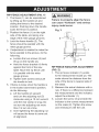
RIPFENCEADJUSTMENT
(FIG. Y)
1. The fence (1) can be repositioned
by lifting up the handle (2) and
sliding the fence to the desired
location. Pushing down the handle
locks the fence in position.
2. Position the fence (1) on the right
side of the table, and along one
edge of the miter gauge grooves.
3. Lock the fence handle (2). The
fence should be parallel with the
miter gauge groove.
4. If adjustment is needed to make the
fence parallel to the groove, do the
following:
o Loosen the two screws (3) and
lift up on the handle (2).
o Hold the fence bracket (4) firmly
against the front of the saw
table. Move the rip fence until
it is parallel with the miter
gauge groove.
o Tighten both screws and push
the handle to lock.
5. If fence is loose when the handle is
in the locked (downward) position,
do the following:
o Lift the handle (2) upward
and turn the adjusting nut (5)
clockwise using a 10 mm wrench
until the rear clamp is snug. Do
not turn the adjusting nut more
than 1/4 turn at a time.
o Over-tightening the adjusting nut
will cause the fence to come out
of alignment.
WAR.l.e]
Failure to properly align the fence
can cause "kickback"
and serious
injury could occur.
Fig. Y
4
RIP FENCE INDICATOR ADJUSTMENT
(FIG. Z)
1. The rip fence indicator (1) points
to the measurement scale (2). The
scale shows the distance from the
side of the fence to nearest side of
the blade.
2. Measure the actual distance with a
rule. If there is a difference between
the measurement and the indicator,
adjust the indicator (1).
3. Loosen the screw (3) and slide the
indicator to the correct measurement
on the scale (2). Tighten the screw
and remeasure with the rule.
Fig.Z
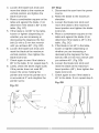
ADJUSTING THE TABLE INSERT
(FIG. BB)
1
WAR.I.G
]
To avoid serious injury, the table
insert (1) must be level with the table.
If the table insert is not flush with the
table, adjust the two bolts (2) with a
4 mm hex wrench until it is parallel with
the table.
2
3
ADJUSTING MITER GAUGE (FIG. AA)
1. Loosen the lock handle (1) to allow
the miter body (2) to rotate freely.
Position the miter body (2) at 90 °
so the positive detent secures its
position. Tighten the lock handle to
hold the miter body in position.
2. if the pointer (3) requires
adjustment, loosen the screw (4)
with a screwdriver. Adjust the
pointer to 90 ° on the scale, then
firmly tighten the adjustment screw.
3. To change angles on the miter
gauge, loosen the lock handle (1)
and rotate the miter body (2) to
the desired angle as indicated by
the scale. Secure in position by
tightening the lock handle (1).
Fig. AA
NOTE: To raise the insert, turn the hex
screws counterclockwise, to lower the
insert, turn the hex screws clockwise.
Do not remove the insert, adjustments
need to be made with the insert in
place to get the proper level.
Fig. BB
ADJUSTING THE 90 ° AND 45 °
POSTIVE STOPS (FIG. CO, DD)
Your saw has positive stops that will
quickly position the saw blade at 90 °
and 45 ° to the table. Make adjustments
only if necessary.
90 ° Stop
1 Disconnect the saw from the power
source.
2. Raise the blade to the maximum
elevation.
3. Loosenthebladelockknoband
movethebladetothemaximum
verticalpositionandtightenthe
bladelockknob.
4. Placea combination
squareonthe
tableandagainsttheblade(1)to
determineifthebladeis90°tothe
table.(Fig.CC)
5. If thebladeis not90°tothetable,
loosenor tighten(depending
on
whetheryouareincreasing
or
decreasing
thedegrees)thehex
bolt(3)witha 5 mmhexwrench
untilyouachieve90°. (Fig.DD)
6. Loosenthebladelockknoband
resetthebladeatthemaximum
verticalposition,thentightenthe
bladelockknob.
7. Checkagaintoseeifthe bladeis
90° tothetable.If not,repeatstep5.
8. Lastly,checkthebevelanglescale.
If thepointerdoesnotread90°,
loosenthescrewholdingthe
pointerandmovethepointerso it
is accurateat0° andretightenthe
pointerscrew.
45 ° Stop
1. Disconnect the saw from the power
source.
2. Raise the blade to the maximum
elevation.
3. Loosen the blade lock knob and
move the blade to the maximum
bevel position and tighten the blade
lock knob.
4. Place a combination square on the
table and against the blade (2) to
determine if the blade is 45 ° to the
table. (Fig. CC)
5. If the blade is not 45 ° to the table,
loosen or tighten (depending on
whether you are increasing or
decreasing the degrees) the hex
bolt (4) with a 5 mm hex wrench until
you achieve 45 °. (Fig. DD)
6. Loosen the blade lock knob and
reset the blade at the maximum
bevel position (45°), then tighten the
blade lock knob.
7. Check again to see if the blade is
45 ° to the table. If not, repeat step 5.
Fig. DD
Fig.CC
90 °
45 °
3
4
BLADETILTPOINTER
(FIG.EE)
1. Whenthebladeis positioned
at90°,
adjustthebladetiltpointer(1)to
read0° onthescale.
2. Loosentheholdingscrew(2),
positionthe pointerover0°and
tightenthescrew.
NOTE:Makea trialcutonscrap
woodbeforemakingcriticalcuts.
Measureforexactness.
Fig.EE
@
2
5. Place the combination square
base (1) into the right side miter
gauge groove (2).
6. Adjust the rule so it touches the front
marked tooth and lock ruler so it holds
BLADE PARALLEL TO THE MITER
GAUGE GROOVE (FIG. FF)
WARNING
I
This adjustment was made at the
factory, but it must be rechecked
and adjusted if necessary.
{A
WARNING
1. Remove the safety switch key and
unplug the saw.
2. Remove the blade guard for this
procedure but reinstall and realign
after adjustment.
3. Raise the blade to the highest
position and set at the 0° angle
(90 ° straight up).
4. Select and mark, with a felt tip
marker, a blade tooth having a
"right set" and rotate the blade so the
marked tooth is 1/2 in. above
the table.
l
To prevent personal injury:
o Always disconnect plug from the
power source when making any
adjustments.
o Inaccurate adjustment can result
in kickback and serious personal
injury. This adjustment must be
correct or accurate cuts cannot
be made.
its position in the square assembly.
7. Rotate the blade bringing the
marked tooth to the rear and about
1/2 in. above the blade.
8. Carefully slide the combination
square to the rear until the ruler
touches the marked tooth.
9. If the ruler touches the marked tooth
at the front and rear position, no
adjustment is needed at this time.
If not or the base of the rule is no
longer parallel with the edge of the
miter gauge groove, see adjustment
procedure described in next section.
Fig. FF
j2
i!!i!!;;_ii!!i!!i!!iiiii:ii!::ii
ADDiTiONAL
BLADEADJUSTMENTSALIGNING
(FIG.GG)
(FIG. HH)
THE RIVING KNIFE
NOTE: The adjusting mechanism is
located above the the blade elevation/
i,a,WAR.I.G
I
tilting handwheel under the table top.
If the front and rear measurements are
not the same:
e To avoid injury from an accidental
start, make sure the switch is in
the OFF position and the plug
is disconnected
from the power
source outlet.
if the blade is partial to right side:
1. Turn the left adjustment screw (1)
counterclockwise and adjust the
right side adjustment screw (2)
clockwise.
2. Remeasure, as described in steps 4
to 9 in the prior section.
3. When alignment is achieved, turn
the left adjustment screw (1) until it
touches the pivot rod (3).
if the blade is partial to left side:
1. Turn the right adjustment screw (2)
counterclockwise and adjust the
left side adjustment screw (1)
clockwise.
2. Remeasure, as described in steps 4
to 9 in the prior section.
3. When alignment is achieved, turn
the right adjustment screw (2) until
it touches the pivot rod (3).
Fig. GG
/
3
o Never operate this tool without
the riving knife in the correct
position.
o Never operate this tool without
the blade guard in place for all
through sawing operations.
o This adjustment was made at the
factory, but it should be rechecked
and adjusted if necessary.
1. Remove the table insert and raise
the blade to the maximum height
by turning the blade elevation/tilting
handwheel clockwise.
2. Remove the blade guard and antikickback pawls assembly.
3. Loosen the blade lock knob. Turn
and move the blade elevation/tilting
handwheel to 0 ° on the bevel
scale, and then tighten the blade
lock knob.
4. To see if the blade (1) and riving
knife (2) are correctly aligned, lay
a combination square (3) along the
side of the blade and against the
riving knife (making sure the square
is between the teeth of the blade).
5. Tilt the blade to the 45 ° position and
check the alignment again.
6. If the blade and riving knife are not
correctly aligned:
a. Remove the lock lever (4),
washer (5), set plate (6) and
riving knife (2) from the mounting
bracket (7).
b. Insert the washer (8) between
the riving knife and bracket (7).
c. Replace the riving knife (2), set
plate (6), washer (5) and lock
lever (4). Then, retighten the
lock lever (4)
,
Check the riving knife and blade
alignment again at both 0 ° and 45 °.
8. Add or remove the washers until the
alignment is correct.
9. Replace the table insert, blade guard
and anti-kickback pawls assembly.
Fig. HH
o The tip of the riving knife shall not
be lower than 0.04 in. ~ 0.2 in.
from the tooth peak.
o The riving knife is thinner than the
width of the kerf by approximately
1/64 in. on each side.
o The blade body must be thinner
than the thickness of the riving knife
but the blade kerf must be thicker
than the riving knife,
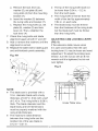
ADJUSTING CAM LOCKING LEVER
(FIG. II)
If the extension table moves when
it is open and locked, then the cam
locking lever (1) may be loose and need
adjustment, To adjust the locking lever
tension, turn the nut (2) with an 8 mm
wrench until it is tightened, but do not
over tighten,
NOTE:
®
This table saw is provided with a
10 in. diameter blade with a body
thickness of 0.07 in. thick with a kerf
of 0.10 in. The riving knife is 0.09 in.
thick. The blade diameter and the
blade body and kerr dimensions
must be properly matched with the
riving knife thickness.
The maximum radial distance
between the riving knife and the
toothed rim of the saw blade is
0.12 in ~ 0.31 in.
Under Table View
BASICSAW
OPERATIONS
l,_
l
ALWAYS lock the switch "OFF"
when the saw is not in use. Remove
the safety switch key and keep it in
a safe place, in the event of a power
failure, blown fuse, or tripped circuit
breaker, turn the switch "OFF"
and remove the safety switch key,
preventing an accidental startup
when power comes on.
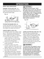
RAiSiNG THE BLADE (FIG. J J)
To raise or lower the blade, turn the
blade elevation/tilting handwheel (1)to
the desired blade height.
Fig. JJ
1
WARNING
2
Fig. KK
3
TILTING THE BLADE (FIG. JJ)
Loosen the blade lock knob (2), move
the handwheel (1) to the desired angle,
then tighten the blade lock knob (2).
2_
ON/OFF SWITCH (FIG. KK)
The ON/OFF switch has a safety switch
key (1). With the key removed from the
switch, unauthorized and hazardous
OVERLOAD PROTECTION (FIG. KK)
This saw has an overload reset
button (3) that resets the motor after
it shuts off due to overloading or low
voltage. If the motor stops during
operation, turn the ON/OFF switch
to the OFF position. Wait about five
minutes for the motor to cool, then
push the reset button (3) and turn the
switch to the ON position.
use by children and others is minimized.
1. To turn the saw ON, insert the
safety switch key (1)into the slot
in the switch (2). Move the switch
upward to the ON position.
2. To turn the saw OFF, press the
switch downward.
3. To lock the switch in the OFF
WARNING]
position, grasp the yellow part of the
safety switch key (1), and pull it out.
4. With the safety switch key removed,
the switch will not operate.
5. If the safety switch key is removed
while the saw is running, it can be
turned OFF but cannot be restarted
To avoid injury, the ON/OFF switch
should be in the OFF position and
the plug removed from the power
source while the cool down takes
place, to prevent accidental starting
when the reset button is pushed.
Overheating may be caused by
misaligned parts or a dull blade or
without inserting the safety switch
key (1).
35
_,
undersized extensing cord. Inspect
your saw for proper setup before
using it again.
USING THE DUST PORT (FIG. LL)
WARNING
l
To prevent fire hazard, clean and
remove sawdust from under the
saw frequently.
To prevent sawdust buildup inside the
saw housing, attach a vacuum hose (1)
(hose is not included) to the dust port (2)
at the rear of the table saw. DO NOT
operate the saw with the hose in place
unless the vacuum is turned on.
Fig. LL
CUTTING OPERATIONS
There are two basic types of cuts:
ripping and crosscutting. Ripping is
cutting along the length and the grain of
the workpiece. Crosscutting is cutting
either across the width or across the
grain of the workpiece. (It is not safe to
rip or crosscut by freehand). Ripping
requires the use of the rip fence, and
crosscutting requires the miter gauge.
NEVER USE A RIP FENCE AND
MITER GAUGE TOGETHER.
%
2
1
USING THE TABLE EXTENSION
(FIG. MM)
1. Release the extension cam locking
levers (1) in the front and rear table
positions.
2. Slide the table extension (2) out
until the correct measurement is
displayed on the tube scale (3). The
user sights the scale off the edge of
the table.
3. Tighten all extension cam locking
levers (1).
WAR.I.G
1
Before using the saw each time,
check the following:
1. The blade is tightened to
the arbor.
2. The blade lock knob is tightened.
3. If ripping, make sure the fence is
locked into position and is parallel
to the miter gauge groove.
4. The blade guard is in place and
working properly.
5. Safety glasses are worn.
Failure to adhere to these common
safety rules, and those printed in
the front of this manual, can greatly
increase the likelihood of injury.
RIPPING (FIG. NN, OO)
[_
WARNING
To make an additional push stick, use
the pattern on page 50. (Fig. OO)
j
To prevent serious injury:
o Never use a miter gauge when
ripping.
o Never use more than one rip
fence during a single cut.
o Do not allow familiarity or
I,A WARNING
i
AVOID KICKBACK by pushing
forward on the section of the
workpiece that passes between the
blade and the fence. Never perform
any freehand operations.
frequent use of your table saw
to cause careless mistakes.
Remember that even a careless
Fig. NN
4
fraction of a second is enough to
cause a severe injury.
Keep both hands away from the
blade and clear from the path of
the blade.
The workpiece must have a
straight edge against the fence
and must not be warped, twisted,
or bowed when ripping.
1. Remove the miter gauge and store
it in the "storage" compartment in
the base of the saw.
2. Secure the rip fence to the table.
3. Raise the blade so it is about 1/8 in.
higher than the top of the workpiece.
2
[_
WARNING]
When width or rip is narrower than
2 in., the push stick cannot be used
because the blade guard will interfere.
Use the auxiliary fence (5) and push
block (6) as shown in Fig. OO.
Fig. O0
4. Place the workpiece flat on the table
and against the fence. Keep the
workpiece away from the blade.
5. Turn the saw ON and wait for the
blade to come to full speed.
6. Slowly feed the workpiece into the
blade by pushing forward only on
the workpiece section (1) that will
pass between the blade and the
fence. (Fig. NN)
7. Keep your thumbs off the table top.
When both of your thumbs touch
the front edge of the table (2), finish
ok(3):
3
7
\
4
8. Continue pushing the workpiece (4)
with the push stick (3) or push
block (6 - Fig. OO) until it passes
through the blade guard and clears
the rear of the table. (Fig. NN)
9. Never pull the piece back when the
blade is turning. Turn the switch Off.
When the blade completely stops,
you can then remove the workpiece.
{,_ WARNING
1
Never attempt to pull the workpiece
backwards during a cutting operation.
This will cause kickback and serious
injury to the user can occur. When
the blade completely stops, raise the
anti-kickback pawls assembly (7) on
each side of the riving knife and slide
the workpiece out. (Fig. OO)
BEVEL RIPPING
This cut is the same as ripping except
the blade bevel angle is set to an angle
other than 0 °.
RIPPING SMALL PIECES
To avoid injury from blade contact,
never make cuts narrower than
3/4 in. wide.
1. It is unsafe to rip small pieces.
Instead, rip a larger piece to obtain
the size of the desired piece.
2. When a small width is to be ripped,
and your hand cannot be safely
put between the blade and the rip
fence, use push stick or push block
to pass the workpiece completely
through and past the blade.
HELPFUL DEVICES
In order to make some cuts, it is
necessary to use devices like a push
block, featherboard or auxiliary fence,
which you can make yourself. Here are
some templates for your reference.
FEATHERBOARD (FIG. PP, QQ)
A featherboard is a device used to
help control the workpiece by guiding
it securely against the table or fence.
Featherboards are especially useful
when ripping small workpieces and for
completing non-through cuts.
The end is angled with a number of
short kerfs to give a friction hold on the
workpiece and locked in place on the
table with C-clamps. Test that it can
resist kickback.
WAR.I.G
}
Place the featherboard against the
uncut portion of the workpiece to
avoid kickback that could cause
serious personal injury.
MAKE A FEATHERBOARD (FIG. PP)
Select a solid piece of lumber
approximately 3/4 in. thick, 4 in. wide
and 18 in. long. To make a featherboard,
cut one end of the lumber at 60 degrees,
then cut 8 in. long slots 1/4 in. apart on
the angled end as shown in Fig. PP.
Fig. PP
8 n.
T-i,
18in.
,
'1
USE A FEATHERBOARD (FIG. QQ)
1. Lower the saw blade (1).
2. Position the rip fence (2) to the
desired position and lock the
rip fence.
3. Place the workpiece (3) against the
fence and over the saw blade area,
4. Adjust the featherboard (4) to resist
the workpiece forward of the blade.
5. Attached the C-clamps (5) to secure
the featherboard to the edge of
the table.
Make sure the screw heads do
not stick out from the bottom of
the base; they must be flush or
recessed. The bottom must be flat
and smooth enough to rest on the
saw table without rocking.
Fig. RR
3/8 in. thick plywood base
i
-7-1
Fig. QQ
1
5
WARNING
I
3
%
.d I I_`
!
21
in.
,i_
|
The edge must be
parallel with the face
AUXILIARY FENCE (FIG. RR)
Making the base:
o Start with a piece of 3/8 in. plywood
at least 5-1/2 in. wide or wider and
21 in. long or longer.
o Cut the piece to shape and size
as shown.
Making the side:
o Start with a piece of 3/4 in.
hardwood at least 1-3/4 in. wide or
wider and 21 in. long or longer.
o Cut the piece to shape and size
as shown.
Putting it together:
o Fasten the pieces together with glue
and woodscrews.
PUSH BLOCK
Use for ripping operation when the
workpiece is too narrow to use a push
stick. Always use a push block for rip
widths less than 2 inches,
MAKE A PUSH BLOCK (FIG. SS)
Making the base:
o Start with 3/8 in. plywood at least
5-1/2 in. wide or wider and 12 in.
long or longer.
o Cut the piece to shape and size
as shown.
Making the handle:
o Start with 3/4 in. hardwood at least
5 in. wide or wider and 7 in. long or
longer.
o Cut the piece to shape and size
as shown.
Making the bracket:
o Start with 3/8 in. wood at least
3/8 in. wide or wider and 2-1/2 in.
long or longer.
o Cut the piece to shape and size
as shown.
Putting it together:
o Fasten the base and handle
together with glue and woodscrews.
l,_
WARNING
i
Make sure the screw heads do not
stick out from the bottom of the base,
they must be flush or recessed.
o Fasten the base and bracket
together with glue.
i,_
WARNING
1
To avoid injury, do not use the screws
to fasten the base and bracket.
Fig. SS
131
%
II
,.-:
I
t I .........I
2
CROSSCUTTING
(FIG. TT)
WARNING
1
To prevent serious injury:
o Do not allow familiarity or
frequent use of your table saw
to cause careless mistakes.
Remember that even a careless
fraction of a second is enough to
cause a severe injury.
Keep both hands away from the
blade and the path of the blade.
Never attempt to pull the
workpiece backwards during a
cutting operation. This will cause
kickback and serious injury to
the user can occur.
1. Remove the rip fence and place
the miter gauge in the miter gauge
groove on the table.
2. Adjust the blade height so that it
is 1/8 in. higher than the top of
the workpiece.
3. Hold the workpiece firmly against
the miter gauge with the blade path
in line with the desired cut location.
Move the workpiece to a 1 in.
distance from the blade.
4. Start the saw and wait for the
blade to come up to full speed.
Never stand directly in line of the
saw blade path, always stand to
the side of the blade that you are
cutting on.
5. Keep the workpiece (1) against the
face of the miter gauge (2) and flat
against the table. Then slowly push
the workpiece through the blade.
6. Do not try to pull the workpiece
back with the blade turning. Turn
the switch OFF, and carefully slide
the workpiece out when the blade
has completely stopped.
WARNING 1
Always position the larger surface
of the workpiece on the table
when crosscutting
and/or bevel
crosscutting
to avoid instability.
Fig. TT
WARNING
i
Always work to the right side of the
blade during this type of cut. The
miter gauge must be in the right
side groove because the bevel
angle may cause the blade guard to
interfere with the cut if used on the
left side groove.
USING THE WOOD FACING ON THE
MITER GAUGE (FIG. UU)
Slots are provided in the miter gauge
for attaching an auxiliary facing (1)
to make it easier to cut very long or
short pieces. Select a suitable piece of
smooth wood, drill two holes through
it and attach it to the miter gauge with
screws. Make sure the facing does not
interfere with the proper operation of
the saw blade guard. When cutting long
workpieces, you can make a simple
outfeed support by clamping a piece of
plywood to a sawhorse.
1. Lower the blade to the down position.
2. Adjust the blade (1) to the desired
angle, and tighten the blade lock
knob.
3. Tighten the miter gauge lock
handle (2) at 90 ° .
4. Hold workpiece (3) firmly against the
face of the miter gauge throughout
the cutting operation.
Fig. VV
1
Fig. UU
2
3
COMPOUND MITER CROSSCUTTING
(FIG. WW)
00-45 ° BLADE BEVEL & 00-45 °
MITER ANGLE
BEVEL CROSSCUTTING (FIG. VV)
00-45 ° BLADE BEVEL & 90 ° MITER
ANGLE
This cutting operation is the same as
crosscutting except the blade is at a
bevel angle other than 0%
This sawing operation combines a
miter angle with a bevel angle,
IA WAR.I.G
]
Always work to the right side of the
blade during this type of cut. The
miter gauge must be in the right side
groovebecausethe bevelangle
maycausethe bladeguardto
Fig. XX
1
interfere with the cut if used on the
left side groove.
1. Set the miter gauge (1) to the
desired angle.
2. Place the miter gauge in the right
side groove of the table.
3. Set the blade (2) bevel to the
desired bevel angle.
4. Hold workpiece (3) firmly against the
face of the miter gauge throughout
the cutting operation,
Fig. WW
2
i
3
1
MITERING (FIG. XX)
00~45 ° MITER ANGLE
This sawing operation is the same as
crosscutting except the miter gauge is
locked at an angle other than 90 ° .
1. Set the blade (1) to 0 ° bevel angle.
2. Set the miter gauge (2) at the
desired miter angle and lock in
position by tightening the miter
gauge lock handle.
3. Hold the workpiece (3) firmly
against the face of the miter gauge
throughout the cutting operation.
2
USING THE WOOD FACING ON THE
RIP FENCE (FIG. YY)
When performing some special cutting
operations, you can add a wood facing
to either side of the rip fence (1).
1. Use a smooth straight 3/4 in. thick
wood board (2) that is as long as
the rip fence.
2. Attach the wood facing to the
fence with wood screws (3) (not
included) through the holes in the
fence. Awood fence should be used
when ripping material such as thin
paneling to prevent the material
from catching between the bottom
of the fence and the table.
Fig. YY
NON-THROUGH
CUT(FIG.ZZ)
Anon-through
cutis usedto cut
groovesandrabbetsintheworkpiece
withoutexposedtheblade.
i_
WARNING
Fig. ZZ
Non-through Cut
1
o Only this type cut is made
without installing the blade guard
assembly and anti-kickback
pawls assembly.
o To avoid injury from an accidental
start, make sure the switch is in
the OFF position and the plug
is disconnected
source outlet.
2
3
from the power
o To avoid the risk of personal
injury. Always use push block,
auxiliary fence and featherboard
when making non-through cut.
1. Before starting the table saw, lower
the blade and riving knife assembly
to the down position.
2. Remove the blade guard assembly
and anti-kickback pawls assembly
for non-through cut.
3. Use the featherboard (1) with
C-clamps (3) to fasten the
workpiece securely.
4. Mount the auxiliary fence (4) with
C-clamps.
5. Use the push block (2) to move the
workpiece.
NOTE: Mount the featherboard to
table as shown, so the leading edges
of featherboard will help workpiece
complete cutting.
1
DADO CUTS (FIG. aa, bb)
I WARNING
1
o Only Stackable dado blades can
be used on this saw.
o DO NOT use Adjustable or
Wobble type dadoes.
o The maximum dado cut width is
1/2 in.
o The maximum dado blade
diameter is 6 in.
NOTE: An dado insert plate (part
number 308K not included) is required
for this procedure.
.
Remove the table insert, saw blade,
anti-kickback pawls assembly,
blade guard assembly and riving
knife assembly for dado cuts ONLY.
Reinstall and realign blade guard
for all through-sawing operations.
Install a dado not exceeding 6 in. in
diameter and 1/2 in. in width.
2. Installthedadotableinsertmaking
surethattherearofthe insertis
flushwiththetable.If thedado
insertis notflushwiththetable,
adjustthetwoboltsonthe insert
witha 4 mmhexwrenchuntilit is
parallelwiththetable.
3. Instruction
foroperating
thedado
is packedwiththeseparately
purchased
dadoset(notincluded
withunit).
4. Thearbor(1)onthissawrestricts
the maximum
widthofthecutto
1/2in.
5. It is notnecessary
toinstallthe
outsideflange(2)beforethreading
onthearbornut(3)forthe
maximum1/2in.dadocuts.Make
surethatthearbornut(3)istight,
andthatat leastonethreadofthe
arborsticksoutpastthenut.
6. Useonlythecorrectnumberof
roundoutsidebladesandinside
chippersasshowninthedadoset's
instruction
manual.Bladeor
chippersmustnotexceed1/2in.
totalinwidth.
7. Checkthesawtoensurethatthe
dadowillnotstrikethehousing,
insert,or motorwhenin operation.
Fig.aa
IIII
_v,
_J
Jl
2
1/
411/h
t-_ al--,,
fJ_
r4LJ
V4_
---1
-...,
\..
3
I_,
WARNING
i
For your own safety, always replace
the blade, blade guard assembly,
anti-kickback pawls assembly, riving
knife assembly and table insert when
you finish the dado operation.
Fig. bb
Dado cut
MAINTAINING YOUR TABLE SAW
BLADE RAISING AND TILTING
MECHANISM (FIG. co, dd)
After every five hours of operation,
the blade raising mechanism and
tilting mechanism should be checked
for looseness, binding, or any other
abnormalities.
1. With the saw disconnected from the
GENERAL MAINTENANCE
WARNING
l
For your own safety, turn the switch
OFF and remove the switch key.
Remove the plug from the power
source outlet before maintaining or
lubricating your saw.
power source, turn the saw upside
down and pull up and push down on
the motor unit.
1. Clean out all sawdust that has
accumulated inside the saw cabinet
and the motor.
2. Polish the saw table with an
2. Observe any movement of the
motor mounting mechanism.
3. Loosen or tighten the four hex
screws (1) by hex wrench for smooth
operation. Adjust only 1/8 turn at a
time. (Fig. cc)
NOTE: Do not adjust the screw
more than 1/2 turn in total as this
automotive wax to keep it clean
and to make it easier to slide the
workpiece.
3. Clean cutting blades with pitch and
gum remover.
4. A worn, cut, or damaged power cord
should be replaced immediately.
[_
WARNING
may damage the mechanism.
Fig. cc
i
1
.®:
All electrical or mechanical repairs
should be attempted only by a
trained repair technician. Contact
customer service for assistance. Use
_ .......
1
only identical replacement parts. Any
other parts may create a hazard.
5. Use liquid dishwashing detergent
and water to clean all plastic parts.
NOTE: Certain cleaning chemicals
can damage plastic parts.
6. Avoid use of cleaning chemicals or
solvents, ammonia and household
detergents containing ammonia.
.
Place a small amount of dry
lubricant on the bevel gear (2). The
worm gear (3) must be kept clean
and free of sawdust, gum, pitch,
and other contaminants for smooth
operations. (Fig. dd)
45
_,
The carbon brushes included with the
Fig. dd
unit will last approximately 50 hours
of running time, or 10,000 ON/OFF
cycles. Replace both carbon brushes
when either has less than 1/4 in. length
of carbon remaining, or if the spring or
wire is damaged or burned.
1. Remove the blade guard, blade,
rip fence, miter gauge and stand
assembly from the table saw.
2. Lower the blade height to its
minimum setting. This will make the
brush locations easier to access.
3. Place cardboard or an old blanket
NOTE: If excessive looseness
is observed in any part of the
blade raising mechanism or tilting
mechanism, take the complete unit to a
Service Center.
on the floor to protect the saw table
surface.
4. Place the saw upside down on the
protective material.
5. Tilt the blade elevation/tilting
handwheel (1) to the 45 ° position.
(Fig. ee)
6. Remove the black plastic cap (2)
from the side of the motor (3).
LUBRICATION
All motor bearings are permanently
lubricated at the factory and require no
additional lubrication. On all mechanical
parts of your table saw where a pivot
or threaded rod are present, lubricate
using graphite or silicone. These dry
lubricants will not hold sawdust as
Fig. ee
would oil or grease.
REPLACING THE CARBON
BRUSHES (FIG. ee, ff)
lAi,WARNING
1
Always disconnect the plug from
the power source before inspecting
the brushes,
46
7. Carefully remove the spring-loaded
cap, and then pull out the brush (4)
and replace. (Fig. if)
8. Repeat step 6 and 7 for the other
side of motor.
9. Place the new brush into the
opening of motor, making sure the
ears on the metal end of the
assembly go in the same hole the
carbon part fits into. Do not
overtighten the plastic cap.
10.Carefully set the saw in a upright
position on a clean level surface.
11. Replace the blade guard, blade,
rip fence, miter gauge and stand
assembly to the table saw.
NOTE: To reinstall the same brushes,
first make sure the brushes go back in
the same sides they came out.
This will avoid a break-in period that
reduces motor performance and
increases wear.
Fig. ff
4
\
\
2
3
WARNING
l
To avoid injury from accidental starting, always turn switch OFF and unplug
the tool before moving, replacing the blade or making adjustments,
PROBLEM
POSSIBLE CAUSES
Saw will not
start.
1. Saw is not plugged in.
1. Plug in saw.
2. Fuse blown or circuit breaker 2. Replace fuse or reset circuit
breaker.
tripped.
3. Cord is damaged.
4. Debris in on/off switch
CORRECTIVE ACTION
3. Replace power cord.
4. Remove switch from saw
and separate in half. Clean
any debris accumulated
within.
Does not make 1. Positive stop not adjusted
accurate 45 °
correctly.
and 90 ° rip cuts. 2. Tilt angle pointer not set
accurately.
1. Check blade with square
and adjust positive stop.
2. Check blade with square
and adjust to zero.
Material pinched 1. Rip fence not aligned with
blade when
blade.
ripping.
2. Warped wood, edge against
fence is not straight.
Material binds
1. Riving knife not aligned
on riving knife.
correctly with blade.
1. Check and adjust rip fence.
2. Select another piece of
wood.
Saw makes
1. Replace blade.
2. Turn the blade around.
3. Remove blade and clean
with turpentine and coarse
steel wool.
4. Change the blade.
5. Clean table with turpentine
and steel wool.
unsatisfactory
cuts.
1. Dull blade.
2. Blade mounted backwards.
3. Gum or pitch on blade.
4. Incorrect blade for work being
done.
5. Gum or pitch on blade
causing erratic feed.
1. Check and align riving knife
with blade.
IA WARNING l
To avoid injury from accidental starting, always turn switch OFF and unplug
the tool before moving, replacing the blade or making adjustments.
PROBLEM
POSSIBLE CAUSES
CORRECTIVEACTION
Material kicked 1. Rip fence out of adjustment.
back from blade. 2. Riving knife not aligned with
blade.
3. Feeding stock without rip
fence.
4. Riving knife not in place.
5. Dull blade.
Blade does
not raise or tilt
freely.
Blade does
not come up to
speed. Reset
trips too easily.
Machine
vibrates
excessively.
1. Align rip fence with miter
gauge slot.
2. Align riving knife with blade.
3. Install and use rip fence.
4. Install and use riving knife.
(with guard)
5. Replace blade.
6. Push material all the way
6. The operator letting go of
past saw blade before
material before it is past saw
releasing work.
blade.
7. Miter angle lock knob is not 7. Tighten knob.
ti,qht.
1. Sawdust and dirt in elevation/ 1. Brush or blow out loose dusl
and dirt.
tilting mechanisms.
1. Extension cord too light or
too long.
2. Low house voltage.
1. Replace with adequate size
cord.
2. Contact your electric
company.
1. Saw not mounted securely to 1. Tighten all mounting
workbench.
hardware.
2. Bench on uneven floor.
2. Reposition on flat level
surface.
3. Damaged saw blade.
3. Replace blade.
Does not make 1. Miter gauge out of
accurate 45 ° and
adjustment.
90 ° crosscuts.
1. Adjust miter gauge.
PUSH STICK CONSTRUCTION
®
®
®
Use good quality plywood or solid wood
Use 1/2 in. or 3/4 in. material
Push stick MUST be thinner than the width of
material being cut
/
/
/
/
/
/
Drill Hole
For Hanging
Notch To
Prevent Hand
/
/
From Slipping
/"
/
/
/
/
/
/"
/
/
/
/
/
/"
/
/"
/
/
//90 °
20 ° - 3(:
Cut Here To
--
Push 1/2 in. Wood
Cut Here To
Push 3/4 in. Wood
10 IN. PORTABLE TABLE SAW
MODEL NO. 137.415030
WA..I.G]
When servicing use only CRAFTSMAN replacement parts. Use of any other
parts many create a HAZARD or cause product damage. Any attempt to
repair or replace electdcal parts on this Table Saw may create a HAZARD
unless repair is done by a qualified service technician. Repair service is
available at your nearest Sears Service Center.
PARTS LIST FOR TABLE SAW (A)
I.D.
Description
08VH CORD CLAMP
Size
Q'_
I.D.
Descrip'}ion
Size
a'ty
1
0KA4 CR. RE.PAN HD, TAPPING SCREW
M4'16-16
0901 BUSH
1
0KBQ CR. RE.PAN HD, TAPPING SCREW
M5'16-10
1
0B2B NEEDLEPOINTER
1
0KC8 CR. RE.TRUSSHD. TAPPING SCREW M4'16-16
3
0B9P CLAMP
1
0KCA CR. RE.TRUSSHD. TAPPING SCREW M5'12-12
2
0BA4 SPACER
1
0KDG CR. RE.PAN HD, SCREW
M5'0,8-6
2
0BA9 SPACER
1
0KDR CR. RE.PAN HD, SCREW
M5'0.8-10
1
0BAB SHIM
1
0KDW CR. RE.PAN HD, SCREW
M6'1,0-20
2
0BAC SETNUT
1
0KF7 CR. RE.PAN HD, SCREW
M4'0.7-12
2
0BAE ARBOR COLLAR
1
0KJ0
CAP HD. SQ, NECK BOLT
M6'1,0-16
1
1
0KJN CAP HD. SQ, NECK BOLT
M6'1,0-35
1
M5'0,8 T=4
2
0J3P HEX.WRENCH
6#
4 MM
2
0J52 FLATWASHER
_pl6_25-1.2
1
OKMR HEX.NUT
0J58 FLATWASHER
_p5_'14-1
6
OKMS HEX.NUT
M6*1,0T=5
3
0J6K FLATWASHER
_p6_30-4
1
OKMT HEX.NUT
MS*1,25T=5
2
0J6T FLATWASHER
3/16'3/4-1/16
4
OKQW LOCK NUT
M5'0.8 T=5
4
0J72 FLATWASHER
1/4'5/8-1/16
1
OKQX NUT
M6'1,0 T=6
1
0J74 FLATWASHER
1/4'5/8-3/32
1
OKQY LOCK NUT
M8'1,25 T=8
1
0J76 FLATWASHER
1/4'3/4-1/16
1
OKRQ SERRATED
TOOTHEDHEX.FLANGENUT M6'1,0 T=6
0J78 FLATWASHER
1/4'1/2-3/32
1
OKSM STRAINRELIEF
1
OJ7E FLATWASHER
5/16'11/16-1/16
1
OKTK STRAINRELIEF
2
0JAE EXTERNALTOOTH LOCK WASHER _p4
2
OKUW TERMINAL
1
0JAF EXTERNALTOOTH LOCK WASHER _p5
1
OKWU LEAD WIREASS'Y
1
0JB2 WAVE WASHER
1
OLWC ROCKERSWITCH
1
1
OWPL SWITCH KEY
WW-12
0JD1 SPRING PIN
1
1
0JPB HEX. HD. BOLT
M5_0.8-20
2
10K5
HEX.SOC, HD, CAP BOLT
M5'0,8-8
3
0JPJ HEX. HD. BOLT
M6_1.0-40
1
IOLF
HEX.NUT
M6*1,0T=4
2
0JVY HEX.SOC. HD, CAP BOLT
M6_1.0-16
1
212M LEAD WIREASS'Y
0JZY HEX.SOC, TRUSSHD. SCREW
M6_1.0-12
1
25AP
HEX.SOC, HD, CAP BOLT
M6'1,0-25
1
0KOX HEX. HD. SCREW AND WASHER
M6_1.0-16
1
25B1 CR. RE.TRUSSHD. SCREW
M5'0,8-25
4
0K3H CR. RE.PAN HD. SCREW& WASHERM6_1.0-12
2
262S
POWERCORD CLAMP
0K74 CR. RE.TRUSSHD, SCREW
M6_1.0-8
2
275R
LOCATION SEAT
6#
1
0KSC CR. RE.COUNTHD. TAPPING SCREWM4_18-10
4
27JR
HEX.SOC, SETSCREW
M5'0,8-6
4
0K9U HEX. HD. TAPPING SCREW
4
2A48
HEX.HD. SCREW AND WASHER
M5'0,8-16
7
M5_16-25
1
2
10 iN. PORTABLE TABLE SAW
MODEL NO. 137.415030
PARTS LiST FOR TABLE SAW (B)
I.D.
Descrip_'ion
Size
2BNW SEAT
Qt"y LD.
Descrip_'ion
Size
2
32V4
SWITCHBOX ASS'Y
2BNX SHAFT
1
34VT
LOCK KNOB
KR#
2E3K CR. RE.ROUND WASHER HD. SCREW M5'0,8-10
2
3E7G
DUSTCOLLECTOR
6#
2ESS LOCKING ROD
1
3EWU
HANDLE
KR#+6#
2
3EWW
EXTENSIONWING (RIGHT)
CQ#
2JHQ SLIDING BASEASS'Y
2
3EWY
TABLE
CQ#
2RVJ CLAMPER BRACKET
1
3EWZ
UPPERTUBE
2RVM GEAR
1
3EX0
REAROUTFEEDSUPPORTTUBE
2RVP SETPLATE
1
3EX1
HANDLE
2RVR GUIDE CLAMP
4
3EX5
BODY
2RVW RETAINING CLIP
1
3EX8
WHEEL
6#
2RW3 RETAINING CLIP
1
3EX9
BODY SHELL
KQ#
1
3EXA
RIVING KNIFE
2SE0 ANCHOR PLATE
1
3EXB
REAROUTFEEDSUPPORT
2SJU SPACER
1
3F49
CIRCUIT BREAKERSWITCH
2T6E CLAMP ASS'Y
1
3FAS
RIP FENCEASS'Y
2TD0 COLLAR
1
3FAT
ANTII-KICKBACK PAWLS ASS'Y
2TDD WORM
1
3H1M
HANDLE BAR ASS'Y
2TDL FLATWASHER
1
3H2X
KNOB
KR#
2TLZ POINTERBRACKET
1
3H2Z
PUSHSTICK
KR#
2VZl
4
3H3V
LOCKING HANDLE ASS'Y
2WEF LOCATION SEAT
2
3G21
CLAMP HANDLE ASS'Y
2X1T PUSHIN PIN
2
3G2Q
TILTINGSCALE
2X6V BOX-END WRENCH
1
3G2W
WARNING LABEL
2X74 OPEN-END WRENCH
1
3G2X
WARNING LABEL
2YF8 BACK UPPERTUBE(RIGHT)
1
3G3X
WARNING LABEL
2YGQ RETAINING CLIP
2
3GSM
OPERATOR'SMANUAL
2YGT ANGLE ROD
1
3GVK
BLADE
2YJ0
1
3GWU
LABEL
1
3GWW SCALE
2HT1 CR. RE.TRUSSHD. TAPPING SCREW
2RW6 SETPLATE
M5'12-8
6#
RUBBERINSERT
SPACER
2YV2 HEIGHTREGULATING BOLTASS'Y
302W FLATWASHER
_p6'21-3
1
3GWX
SCALE
3081
M5'0,8-12
4
3GWY
SCALE
3GX0
TRADEMARK LABEL
CR. RE.PAN HD PLAIN WASHER
TAPPING SCREW
308C POWER CABLE
1
3GY5
TABLEiNSERTASS'Y
308E POWER CABLE ASS'Y
1
3GZC
STICKER
308G NEEDLEPOINTER
1
3H5T
MOTOR ASS'Y
309H WASHER
1
3H67
BLADE GUARD ASS'Y
30C2 HEX, HD, TAPPING SCREW
M5'16-16
6#
KR#+6#
10 3H69
SUPPORT
30JU WARNING LABEL
2
3H6A
MITERGAUGE ASS'Y
30NM SPECIAL BOLT
2
_308K
DADO INSERTPLATE(not included)
Q"}y
10 IN. PORTABLE TABLE SAW
SCHEMATIC
MODEL NO. 137.415030
3FAT
/
/
/
/
/
i
I
I
10iN.
PORTABLE TABLE SAW
PARTS LiST FOR MOTOR
MODEL NO. 137.415030
I.D.
Description
0HX9
NEEDLE BEARING
Size
Q'iy
0JX3
HEX. SOC. SETSCREW
M5"0.8-8
2
0KCN
CR. RE. PAN HEAD TAPPING & WASHER SCREW
M5"12-50
2
0KTK
STRAIN RELIEF
1
0QFE
BRUSH COVER
2
0QFF
CARBON
2
0QFG
BRUSH HOLDER ASS'Y
2
2DW9
WAVE WASHER
1
2RPP
FLOW GUIDE
2RWS
CR. RE. COUNTER-SUN HEAD SCREW
2RXC
LABEL
2YF5
BRACKET
2YH8
MOTOR COVER
30L5
ARMATURE ASS'Y
3235
CR. RE. PAN HD. SCREW & WASHER
33F7
FIELD ASS'Y
1
3H5U
CUTTER SHAFT ASS'Y
1
1
BRUSH ASS'Y
1
M5"0.8-10
2
1
1
6#
1
M5"0.8-55
4
1
)QFE2
33F7
10 iN. PORTABLE TABLE SAW
PARTS LiST FOR STAND
MODEL NO. 137.415030
I.D.
DescfiF}ion
Size
0J4R
FLATWASHER
cp10'20-3
Q'_
4
I.D.
Descrip_'ion
30B1 WARNING LABEL
Size
0J5G
0JPS
FLATWASHER
HEX. HD. BOLT
cp8'18-1.5
M8'1.25-45
0JUL
0JVB
HEX.SOC. HD. CAP BOLT
HEX.SOC. HD. CAP BOLT
M6'1.0-20
M5'0.8-16
0K7F
0KDK
4
4
30XP
FLATWASHER
30Z0
NUTCHUCK
cp6'13-1
4
M6'1,0 T=6 4
2
3
34XF
372V
PLATE
END-CAP
6#
1
1
CR. RE.ROUND WASHERHD. SCREWM5'0.8-8
8
37T2
CR. RE.TRUSSHD. SCREW
M6 _1.0-40
4
CR. RE.PAN HD, SCREW
M5'0.8-16
1
3F3J
SUPPORT
6#
1
0KQW LOCK NUT
M5'0.8 T=5
4
3F3L
CONNECTOR TUBE
6#
2
0KQX NUT
M6'1.0 T=6
2
3F3M ROD
1
0KQY LOCK NUT
157B HEX.SOC, HD, CAP BOLT
M8'1.25 T=8
M5'0.8-45
6
1
3F3N SLEEVE
3F3S BOTTOMBRACKETASS'Y
6#
2
1
270N
NUT CHUCK
M10'1,5 T=8
2
3F3T CASTER
6#
2
270P
HEX.SOC. TRUSSHD, SCREW
M8'1.25-60
1
3F3W BOTTOMBRACKET
6#
1
2888
CAP HD, SQ. NECK BOLT
M8'1.25-50
5
3F3X
HANDLE
6#
2
2FU9
COLLAR
PLUNGERHOUSING
6#
1
6#
2
3F3Y
2HDS WING NUT
MS*1.25-2B
1
2JQD
6#
1
3F3Z COLLAR
3F63 GRiP
2JQM HEX. HD. BOLT
2LAL BUSH
M10'1,5-90
2
4
3G1V HANDLE
2T9J
M3.5'20-8
LEVELINGPAD
CR. RE.PAN HD, TAPPING SCREW
1
2
KR#
3G32 WARNING LABEL
2
3GTW CR. RE.TRUSS
HD. ROUNDNECKSCREWM6'1.0-10
2WV3 ANCHOR PLATE
1
3GWV CAUTION LABEL
2WVF COMPRESSIONSPRING
2
3GWZ SCALE
3H4G HINGA
2X6Q END CAP
2Y7K ANCHOR PLATE
_JQD
2HDS
OKDK
6#
1
1
a'fy
1
KR#
3F3T 2,
55
q
Congratu/ations on rnaking a smart purchase. Your new Craftsman ® product
is designed and manufactured for years of dependable operation. But like all
products, it may require repair from time to time. That's when having a Repair
Protection Agreement can save you money and aggravation.
Here's what the Repair Protection
[]
[]
[]
[]
[]
Agreement*
includes:
Expert service by our 10,000 professional repair specialists
Unlimited service and no charge for parts and labor on all covered
repairs
Product replacement up to $1500 if your covered product can't be fixed
Discount of 25% from regular price of service and related installed
parts not covered by the agreement; also, 25% off regular price of
preventive maintenance check
Fast help by phone - we call it Rapid Resolution - phone support from a
Sears representative. Think of us as a "talking owner's manual."
Once you purchase the Repair Protection Agreement, a simple phone call is all
that it takes for you to schedule service. You can call anytime day or night, or
schedule a service appointment online.
The Repair Protection Agreement is a risk-free purchase. If you cancel for any
reason during the product warranty period, we will provide a full refund. Or, a
prorated refund anytime after the product warranty period expires. Purchase
your Repair Protection Agreement today!
Some limitations and exclusions apply. For prices and additional
information in the U.S.A. call 1=800=827-6655.
*Coverage in Canada varies on some items. For full details call Sears
Canada at 1=800=361=6665.
Sears Installation Service
For Sears professional installation of home appliances, garage door openers,
water heaters, and other major home items, in the U.S.A. or Canada call
1-800-4-MY-HOME ®.