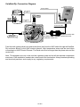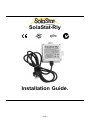
1
ST E RE
D
I
SolaStat-Rly
TECHNOLOGY
& QUALITY
A WA R D
E
R
REG
1
900
ISSO
UP LI
P
Z985
Installation Guide.
19.05-1
SolaStat-Rly Installation Guide Index.
Description, Ordering and Specifications.
Index
Features
Introduction
Ordering Information.
page 2
page 3
page 3
page 3
SolaStat-Rly Users Guide.
Principle of Operation.
page 4
SolaStat-Rly Safety Instructions.
General Safety Instructions.
Installation Precautions.
Electrical Precautions.
page 4
page 4
page 4
SolaStat-Rly Mounting and Wiring.
SolaStat-Rly Mounting.
SolaStat-Rly Wiring.
SolaStat-Rly Connection Diagram.
Page 5
Page 5
Page 6
SolaStat-Rly Specifications and Limit of Liability.
Specifications
Product Liability.
page 7
page 7
19.05-2
SolaStat-Rly. Slave Relay
for SolaStat Controllers.
·
·
I
R
REG
1
900
ISSO
I
UP L
P
Fully isolated relay (contactor).
Different voltages and wiring can operate safely together.
Prewired Plug.
Simple and versatile connection
of SolaStat-Plus-2 to HWC.
Electrician can install the SolaStat-Rly
at a different time than the Solar Hot Water
professional installs the SolaStat-Plus-2.
High power rated contacts.
Low power levels through SolaStat controller wiring
(2 W switches 7kW).
E
·
ST E RE
D
Features.
TECHNOLOGY
& QUALITY
AWA R D
Z985
SolaStat Models Include:
SolaStat-Eco: Controller c/w 4 Status Lights.
SolaStat-Plus: Controller c/w Display.
SolaStat-Pool: Pool Controller c/w Display.
SolaStat-Rmt: Remote Display.
SolaStat-Rly: Slave Relay for HWC Control.
SolaData: PC Datalogging & Comms.
Introduction.
SolaStat-Rly is Versatile; An easy to install slave relay or contactor complete in an enclosure.
The input is completely isolated from the output contacts. Input and Output in no way share any
common electrical connections. This provides a safe and legal interface between;
·
Different voltages / Different circuits.
·
Permanent and flexible wiring installations.
·
High power 240Vac relay.
- 30 Amp Resistive (7kW electric Element).
- 3HP Inductive (2250W Motor).
·
Low Voltage coil options available.
Senztek NZ Ltd has experience in designing and manufacturing Solar Hot Water Controllers to
Industrial Electronic Standards for over 15 years. This has earned SolaStat a reputation for Quality, Accuracy, Efficiency and Reliability.
Ordering Information.
SolaStat-Rly
SolaStat-Rly
Standard Unit: 180~264Vac Coil; 2m Mains Cable; 30A/3hp Relay,
2 x 20mm Flexible Conduit Glands.
-
G
Specify Conduit Gland size and power supply option.
PS
SolaStat-Rly Ranging Options.
Conduit Size
G
Coil Voltage
180~264Vac
16mm
16
20mm
20
90~132Vac
18~26Vdc
9~13Vdc
PS
H
A
M
L
Note. Ensure specified coil voltage matches the
supply voltage of the SolaStat-Plus-2
controlling the SolaStat-Rly.
Other coil voltages available on special order.
Quality Assurance Programme.
The modern technology and strict procedures of the ISO9001 Quality Assurance Programme applied during
design, development, production and final inspection grant the long term reliability of the instrument.
19.05-3
SolaStat-Rly Users Guide.
Principle of Operation
The SolaStat-Rly contains a relay. The coil of the relay is energised by the SolaStat-Plus-2 (or
other power source) which closes a set of contacts. There is no electrical connection at all between
the input power and output contacts. The coil consumes only 1 or 2 watts of power, but switches
much higher power levels through the contact, that the energized coil closes.
Example 1. (Mains coil version)
An electrician can wire a SolaStat-Rly into a Hot Water Tank electric element without the Solar Hot
Water System installer being there. The solar installer is free to arrive at a different time and date
to plug in the SolaStat-Rly to the SolaStat-Plus-2 which in turn plugs into a wall socket and the
Solar Hot Water System is ready to go (electrically). No more electrical work needed and no
electrical registered person on site.
Example 2. (Low voltage coil version)
A SolaStat-Pool is running off an isolated 12 volt power source. The SolaStat-Pool is close to the
water so the users can easily see and alter the adjustable values (mains power forbidden in this
zone). The pump output is wired to a SolaStat-Rly (low voltage coil option) that controls a mains
powered pump at a safe distance.
SolaStat-Rly Safety Instructions.
Read safety instructions and limit of liability before proceeding with the installation.
General Safety Instructions.
1.
This installation guide is for the installation of SolaStat-Rly Slave Relay only and is not an
installation guide for any other part.
2.
The complete installation should be checked at least annually for damage or malfunction.
3.
All servicing to be carried out by an authorised service agent only.
4.
All aspects of the installation must comply with local electrical regulations.
Installation Precautions.
1.
Must be installed away from water sources such as rain, leaking pipes, or wet floors and
must not be installed in damp areas like bathrooms.
2.
Must not be installed in direct sunlight, near flammable liquids or near radiant heat sources.
3.
Must not installed where the ambient temperature can exceed 50C. Warning; Roof spaces
may exceed 50C. Typically the lower in height the unit is mounted the lower the ambient
temperature it will be subject to.
Electrical Precautions.
CAUTION:
1.
2.
3.
4.
5.
Dangerous Voltages may be present. The SolaStat has no user serviceable parts.
Protective enclosure only to be opened by qualified personnel.
Remove ALL power sources before removing protective cover.
All mains voltage electrical work to be carried out by a qualified electrician, especially hot
water tank electric element wiring installation.
A readily accessible disconnect device and overcurrent device rated to suit the size of the
load must be incorporated in the power supply wiring.
Do not use mains power extension cords unless approved by the manufacturer. Water
resistant plugs and sockets should be used.
Always use within specified voltage and load ranges. Never use with damaged leads, plugs
or sockets.
Keep a minimum of 10mm isolation separation between the relay coil wiring and any HWC
wiring. The coil wiring must be completely isolated from the HWC wiring to class II.
19.05-4
SolaStat-Rly Mounting.
1.
2.
3.
4.
5.
6.
Mount the unit where it is dry and not subject to direct sun or mechanical damage.
The SolaStat-Rly must not be subject to ambient temperatures exceeding 50C. Warning;
Roof Spaces may exceed 50C.
Fix to a surface able to support the weight of the unit, as well as any conduit and wiring.
Allow for cable runs, location of power outlets and lengths of wires.
Remove the lid to access the 4 mounting screw holes. The holes need to be drilled or pushed
out (the plastic is quite thin at the screw bushes).
Screw the unit to the desired surface.
SolaStat-Rly Wiring.
1.
2.
All mains wiring to be done by a registered electrician only.
Electricity Suppliers may remotely turn off the HWC electric element using controlled wiring.
Do not bypass the controlled wiring. The SolaStat-Rly connects between the controlled
wiring and the HWC element.
3.
The 2 available screw terminals on the relay are a normally open contact. The phase (active)
wires should screw to these as shown in the diagram below.
4.
Keep a minimum of 10mm isolation separation between the relay coil wiring and any HWC
wiring. The coil wiring must be completely isolated from the HWC wiring to class II.
5.
Replace the lid when finished.
6.
For SolaStat-Rly-H models with a mains rated input coil and a flexible mains cord for control
(fully isolated so mixed permanent, flexible wiring permissible), the contact will not close until
power is applied to the plug.
a.
If the SolaStat-Plus-2 is already installed then it is a simple matter of plugging it in to
activate the HWC (under SolaStat-Plus-2 intelligent control).
b.
If this is a pre-solar installation (the SolaStat-Plus-2 is not installed/active yet) then the
HWC can only heat water if the SolaStat-Rly is plugged into a power socket and switched
on. This way normal hot water services can continue until the solar hot water system is
installed.
7.
The Hot Water Thermostat for the Electric Element MUST be installed and MUST be set
higher than the temperature of the HWC BioSafe and Reheat adjustable values for the HWC
Control Modes to operate correctly. The Hot Water Thermostat for the Electric Element is only
used as a fail safe feature and in normal operation will never operate. We recommend setting the
Hot Water Thermostat to the Maximum Temperature.
19.05-5
SolaStat-Rly Connection Diagram.
.
SOLASTAT-PLUS-2
DIFFERENTIAL CONTROLLER
TO ROOF SENSOR
(10m)
TANK SENSOR
(2m)
HWC SWITCH
THERMOSTAT
TURNED TO MAX
240Vac
30A MAX
ELECTRIC
HEATING
ELEMENT
INLET SENSOR
(2m)
EARTH
Phase (Brown)
to HWC Switch
TO SOLASTAT PUMP
NEUT
WIRES TO HWC
MUST BE HIGH
TEMPERATURE TYPE
Phase (Brown)
to Element
PRE-WIRED PLUG & LEAD
CONNECTED TO RELAY COIL
PRE-WIRED SOCKET & LEAD
FROM SOLASTAT 'AUX'
SOLASTAT-RLY
Feed the earth (green/yellow) wire and neutral (blue) wire from the HWC switch through the SolaStatRly enclosure directly to the HWC electric element. High temperature wires must be used when
connecting to a HWC Electric Element. The Earth wire must be longer than the phase wire and the
neutral wire.
Note. This diagrams are only to be used as a general guide and not all the required components
are shown. Each installation needs to be customised to suit its situation. Always use best plumbing
and electrical practices, and comply to any regulatory requirements.
19.05-6
.
SolaStat-Rly Specifications.
Note: All ratings at 25C
Power Supply.
Coil Voltage Options -L
-M
-A
-H
Max coil power usage.
Contact Ratings
Relay Idle State
Voltage max
Resistive
Inductive (CosÖ=0.4)
9~13Vdc
18~26Vdc
90~132Vac 50/60Hz
180~264Vac 50/60Hz
2.5 VA
N/O
264Vac 50/60Hz
30Amp (7kW element) @ 240Vac 50/60Hz
3HP (2250W Motor) @ 240Vac 50/60Hz
1.5HP (1125W Motor) @ 120Vac 50/60Hz
EMC and Safety Compliances.
Emissions:
Immunity:
Safety Compliance:
EN 55022-A, CTick.
EN 50082-1.
EN 60950, CTick.
General Specifications.
Operating Temperature:
Operating Humidity:
Enclosure Construction
Dimensions
Weight.
-20~50ºC, No Icing.
5~85% RH Max. Non-Condensing
ABS - Impact Resistant, UL94 V-0
L=100, W=100, H=60mm
Standard model + packaging = 550grams
Product Liability.
This information describes our products. It does not constitute guaranteed properties and is not
intended to affirm the suitability of a product for a particular application. Due to ongoing research
and development, designs, specifications, and documentation are subject to change without
notification. Regrettably, omissions and exceptions cannot be completely ruled out. No liability will
be accepted for errors, omissions or amendments to this specification. Technical data are always
specified by their average values and are based on Standard Calibration Units at 25C, unless
otherwise specified. Each product is subject to the ‘Conditions of Sale’.
Warning.
These products are not designed for use in, and should not be used for patient connected
applications. In any critical installation an independent fail-safe back-up system must always be
implemented.
19.05-7
SolaStat Distributor.
intelligent measurement technology
Web: www.senztek.com
E m a i l : [email protected]
SS-rly installation 250108.p65
19.05-8
© Copyright Senztek Holdings Ltd, 2007