1
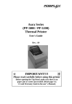
PP4000 Series
Thermal Printer
User's Guide
Rev.: Original
Federal Communications Commission Radio Frequency
Interference Statement
This equipment has been tested and found to comply with the limits for a Class A digital device,
pursuant to Part 15 of the FCC Rules. These limits are designed to provide reasonable protection against
harmful interference when the equipment is operated in a commercial environment. This equipment
generates, uses, and can radiate radio frequency energy and, if not installed and used in accordance with
the instruction manual, may cause harmful interference to radio communications. Operation of this
equipment in a residential area is likely to cause harmful interference in which case the user will be
required to correct the interference at his own expense.
For compliance with Federal Noise Interference Standard, this equipment requires a shielded cable.
This statement will be applied only for the printers marketed in U.S.A.
CE manufacturer’s Declaration of Conformity
(EC Council Directive 89/336/EEC of 3 May 1989)
This product has been designed and manufactured in accordance with the International Standards
EN50081-1/01.92 and EN50082-1/01.92 following the provisions of the Electro Magnetic
Compatibility Directive of the European Communities as of May 1989
Warranty Limits
Warranty will terminate automatically when the machine is opened by any person other than
the authorized technicians. The user should consult his/her dealer for the problem happened. Warranty
voids if the user does not follow the instructions in application of this merchandise. The manufacturer is
by no means responsible for any damage or hazard caused by improper application.
About This Manual
This manual is aimed to assist the user to utilize the PP4000 series which is a series of POS
thermal printers delicately designed to work with either serial or parallel interface connection. This
manual covers both operational and technical aspects. This manual is revised to cover also the Epson
emulation commands and some frequently asked questions.
The manufacturer of the PP4000 series heartily apologizes to the user for reserving the right to
change or to modify this manual without notice due to the rapid and constant progress and improvement
on science and technology. The user may always obtain the most up to date information through our
web site: http://www.posiflex.com.tw .
© Copyright Mustek Corp. 1998
All rights are strictly reserved. No part of this documentation may be reproduced, stored in a
retrieval system, or transmitted in any form or by any means, electronic, mechanical, photocopying, or
otherwise, without the prior written consent of Mustek Corp. the publisher of this documentation.
Table Of Contents
GETTING STARTED . . . . . . . . . . . . . . . . . . . . .
1
CONGRATULATION . . . . . . . . . . . . . . . . . . . . . 1
PRODUCT BRIEFING . . . . . . . . . . . . . . . . . . . . . 1
MODEL NUMBERS . . . . . . . . . . . . . . . . . . . . . . . 1
UNPACKING . . . . . . . . . . . . . . . . . . . . . . . . . . . . . 1
MAIN PARTS ON THE EXTERIOR . . . . . . . . . 1
INDICATORS . . . . . . . . . . . . . . . . . . . . . . . . . . . . 1
OPERATING ENVIRONMENT . . . . . . . . . . . . . 1
USEFUL TIPS . . . . . . . . . . . . . . . . . . . . . . . . . . . . 1
-- 1
-- 1
-- 2
-- 3
-- 4
-- 5
-- 6
-- 7
-- 8
QUICK START-UP . . . . . . . . . . . . . . . . . . . . . . . . 2
-- 1
-- 1
-- 2
-- 3
-- 3
-- 4
-- 4
-- 5
-- 5
-- 6
-- 6
-- 7
LOADING PAPER . . . . . . . . . . . . . . . . . . . . . . . . 2
AUTO PAPER FEED . . . . . . . . . . . . . . . . . 2
MANUAL PAPER FEED . . . . . . . . . . . . . . 2
WHEN TO REPLACE PAPER . . . . . . . . . 2
CONNECTING CABLES . . . . . . . . . . . . . . . . . . 2
SERIAL CONNECTION . . . . . . . . . . . . . . 2
PARALLEL CONNECTION . . . . . . . . . . . 2
PERIPHERAL CONNECTION . . . . . . . . . 2
POWER CONNECTION . . . . . . . . . . . . . . 2
POWER ON . . . . . . . . . . . . . . . . . . . . . . . . . 2
SELF TEST . . . . . . . . . . . . . . . . . . . . . . . . . . 2
MAINTENANCE AND INTERNAL PARTS . . . . 3 -- 1
MAINTENANCE GUIDE LINES . . . . . . . . . . . .
INTERNAL PARTS . . . . . . . . . . . . . . . . . . . . . . .
PAPER JAM . . . . . . . . . . . . . . . . . . . . . . . . . . . . .
PRINT HEAD CLEANING . . . . . . . . . . . . . . . . .
3
3
3
3
-- 1
-- 1
-- 2
-- 2
SPECIFICATIONS . . . . . . . . . . . . . . . . . . . . . . . . . . . 4 -- 1
PRINTER . . . . . . . . . . . . . . . . . . . . . . . . . . . . . . . . 4 -- 1
PAPER . . . . . . . . . . . . . . . . . . . . . . . . . . . . . . . . . . 4 -- 1
i
POWER ADAPTOR . . . . . . . . . . . . . . . . . . . . . . . 4 -- 2
TECHNICAL INFORMATION . . . . . . . . . . . . . . . 5 -- 1
INTERFACES . . . . . . . . . . . . . . . . . . . . . . . . . . . . 5
SERIAL INTERFACE . . . . . . . . . . . . . . . . 5
RS232 . . . . . . . . . . . . . . . . . . . . . . . . . . 5
RS422 . . . . . . . . . . . . . . . . . . . . . . . . . . 5
PARALLEL INTERFACE . . . . . . . . . . . . . 5
PERIPHERAL INTERFACE . . . . . . . . . . . 5
HARDWARE SETTINGS . . . . . . . . . . . . . . . . . . 5
SOFTWARE COMMANDS . . . . . . . . . . . . . . . . . 5
-- 1
-- 1
-- 1
-- 1
-- 2
-- 2
-- 3
-- 5
CHARACTER CODE PAGES . . . . . . . . . . . . . . . . . 6 -- 1
PAGE 0 ENGLISH / JAPANESE . . . . . . . . . . . . 6 -- 1
PAGE 1 ENGLISH / EUROPEAN . . . . . . . . . . . 6 -- 2
ii
I. GETTING STARTED
A. CONGRATULATION
You have made a very wise decision by purchasing the high
speed – low noise –high resolution – light weight – high
reliability thermal printer PP4000 series of Posiflex products. This
series of printers has been elegantly designed for a Point-Of-Sale
application. The manufacturer of this printer not only wishes to
take this opportunity to congratulate your smart investment on
buying this printer but also likes to express the wishes for your
prosperous future by using it.
1-1
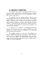
B. PRODUCT BRIEFING
The PP4000 series printer uses thermal sensitive paper in
form of a roll at a width of 80 mm. The PP4000 printer serves the
stand-alone POS application as well as the application within a
PST system equally perfect.
The PP4000 series can support different interface input
through different sub-codes to the model number. The interfaces
include RS232 for serial interface and Centronics for parallel
interface. PP4000 printer of different model number sub-codes
utilizes different connector, accessory cable and part of internal
circuitry to accommodate the requirement of different interface.
As a variation from the RS232 for serial interface, RS422 serial
interface is also available.
In addition to the capability of supporting international
character sets, there are also some models in PP4000 series that
supports the oriental characters as indicated in the following
paragraph about model numbers.
The PP4000 supports an auto cutter. The PP4000 also
supports application in different countries of various kinds of
power systems by changing the power adaptor and/or the power
cord to the power adaptor. The PP4000 further supports some
built-in bar code printing commands for UPC-A, EAN8, EAN13,
CODE 39, ITF and CODABAR.
1-2
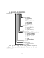
C. MODEL NUMBERS
EXAMPLE:
PP 4 0 0 0 S 0
Power adaptor:
0: No adaptor
1: USA adaptor
2: European adaptor
3: UK adaptor
4: SA adaptor
5: AUS adaptor
Interface:
B: serial (RS422)
C: parallel
S: serial (RS232)
Reserved
Language/Expanded character set
0: English (standard)
1: GB-code Chinese
2: BIG-5 code Chinese
3: Korean
4: Thai
5. Japanese Kanzi
Reserved
Product series
4: thermal printer
POS printer
The last two digits in the model number structure as
explained above are called sub-codes. The rest are the basic
model number.
1-3
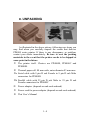
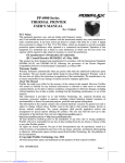
D. UNPACKING
ƒa
ƒb
…
†
„
•
‚
As illustrated in the above picture, followings are items you
may find when you carefully unpack the carton that delivers
PP4000 series printer. If there is any discrepancy or problem,
contact your dealer immediately. Be sure to save the packing
materials in the event that the printer needs to be shipped at
some point in the future.
• The printer itself. Choices are PP4000S, PP4000C and
PP4000B.
‚ Thermal paper roll. 80 mm wide, outer diameter 83 mm max.
ƒa Serial cable with 9 pin D sub Female to 9 pin D sub Male
connectors for PP4000S
ƒb Parallel cable with 25 pin D sub Male to 25 pin D sub
Female connectors for PP4000C
„ Power adaptor. (depends on sub-code ordered)
… Power cord for power adaptor (depends on sub-code ordered)
† This User’s Manual
1-4
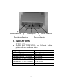
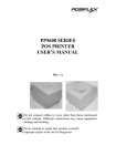
E. MAIN PARTS ON THE EXTERIOR
Top cover
Bottom base
Paper exit slot
Power On / off switch
Power LED (green)
Paper End LED (red)
Paper feed button
1-5
Serial connector
Bottom plate
Peripheral connector
Parallel connector
Power connector
F. INDICATORS
•
•
POWER LED: green
PAPER END INDICATOR: red. Different lighting
pattern indicates each error status.
Lighting pattern
Constant light up
Constant blinking
1 blink plus OFF 1.2 seconds
2 blinks plus OFF 1.2 seconds
3 blinks plus OFF 1.2 seconds
4 blinks plus OFF 1.2 seconds
5 blinks plus OFF 1.2 seconds
1-6
Meaning
Paper End
Paper Near End
ABMARK
HEAD UP
TEMPERR
VOLTERR
HWRERR
G. OPERATING ENVIRONMENT
•
Place the printer on a sturdy, level surface.
•
Choose a place that is well ventilated and free of
excessive dust, smoke or fume.
•
Do not put the printer in direct sunlight or near a heater.
•
Ideal room temperature is from 5ºC to 40ºC. Ideal
humidity is from 20% to 85% RH (no condensation).
•
Since the paper roll is very thermal sensitive, please
keep them in a dark place that is 20º and 65% RH when
not installed in the printer.
•
Use a grounded AC power outlet.
•
Use only the power cord and power adaptor furnished
with the printer.
•
Do not use a power outlet of a circuit shared with any
equipment that causes great electrical noise, such as
motors.
•
Do not use a power outlet of a circuit shared with any
equipment that uses a lot of power, such as a copier or a
coffee maker.
•
Do not touch any connector contacts to avoid possible
electrostatic damage.
1-7
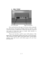
H. USEFUL TIPS
•
Do not pull the paper in the direction opposite to the
paper feeding direction with the print head closed.
•
Do not touch the areas around the print head and motor
during or right after printing. It can be very hot.
•
Do not use thermal paper containing Sodium (Na+),
Potassium (K+) and Chlorine (Cl-) ions that can harm
the print head thermal elements.
•
Use only water paste, starch paste, polyvinyl paste or
CMC paste when gluing thermal paper.
•
Use of volatile organic solvents such as alcohol, ester
and ketone on thermal paper can cause discoloration.
•
Some adhesive tapes on thermal paper may cause
discoloration or faded printing.
•
Use only products made from polyethylene,
polypropylene or polyester for storage of thermal paper.
If thermal paper touches anything includes phthalic acid
ester plasticizer for a long time, the image formation
ability may be reduced or the printed image may fade.
•
If thermal paper touches diazzo copy paper immediately
after copying, the printed surface may be discolored.
•
Thermal paper must not be stored with the printed
surfaces against each other as the printing may be
transferred between the surfaces.
•
If the surface of thermal paper is scratched with a hard
metal object such as a nail, the paper may become
discolored.
1-8
•
Store thermal paper away from high temperature and
humidity. Avoid extended exposure to direct light.
•
Do not set any liquid or drinks such as coffee on the
printer case
1-9
II. QUICK START-UP
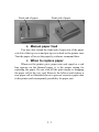
A. LOADING PAPER
Paper roll compartment
Thermal print engine
Open top cover by gently pressing the rear part of cover
inward and lift it up. Take the cover away to expose the paper roll
compartment and the thermal print engine.
Note direction of paper roll
Head-up lever
Rear insert slot
Put the paper roll into the paper roll compartment in the
direction shown as above. Push down the head-up lever on
2-1
thermal print engine and try to aim the front end of the paper roll
toward the rear insert slot.
Tear paper off
Paper feed knob
When the front end is inserted into the rear insert slot, close
up the head-up lever and turn the paper feed knob to roll the paper
forward. If the paper is not inserted in proper position, you may
push down the head-up lever and adjust the position of paper and
close up the head-up lever again.
1. Auto paper feed
This printer automatically feeds paper forward about 4 mm
every time it is powered up or every time the head-up lever is
closed up during power on. Therefore, you may tear the front end
of paper roll off against the auto cutter assembly. You may then
put on the top cover back and have the new front end of paper
come out to the paper exit slot automatically when the printer is
powered on.
2-2
Front end of paper
Front end of paper
2. Manual paper feed
You may also extend the front end of paper out of the paper
exit slot of the top cover and put top cover back to the printer case.
Tear the paper off or cut the paper by software command later.
3. When to replace paper
Whenever the printer gives paper near end signal or a red
line appears on the thermal paper, it is the proper timing for
replacing the paper. Do not wait till the print engine is dragging
the paper roll at the very end. Remove the leftover and replace a
new paper roll as illustrated above to prevent excessive paper dust
in the printer and consequently possibility for paper jam.
2-3
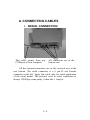
B. CONNECTING CABLES
1. SERIAL CONNECTION
This cable comes from any
COM port of host computer
All connectors are at the
bottom rear
All the external connectors are in the recessed area at the
rear bottom. The serial connector is a 9 pin D sub Female
connector at the left. Apply this cable only for serial application
of the serial model. The protocol used in serial connection is
always 19200 bps, none parity, 8 data bits, 1 stop bit.
2-4
2. PARALLEL CONNECTION
This cable
connects to
LPT port
of the host
computer
The parallel connector is a 25 pin D sub Male connector at
the rightmost location in the connector area. Apply this cable only
for parallel model.
3. PERIPHERAL CONNECTION
This cable
goes to cash
drawer.
The peripheral controller is a RJ11 jack near the serial
connector. With use of Posiflex special split cable (CCBLA-238
as an option) for cash drawer control, this port can control two
cash drawers.
2-5
4. POWER CONNECTION
Pull back the
outer sleeve first
Power connector from power adaptor
The power connector is a 3 pin jack between the peripheral
connector and the parallel connector. During insertion, be sure to
hear the click to obtain a firm contact.
CAUTION: Before doing the insertion or extraction of the
power plug, be sure to pull the outer sleeve of the
plug backward to release the internal latch.
Failure to do this could damage the power plug.
Such damage is considered as an artificial
destruction and is not covered by the warranty.
5. POWER ON
When all the above cable connections are made correctly,
you may connect your power adaptor to the wall outlet. Make
sure that the type of power cord and the voltage requirement of
the power adaptor meet the local power conditions. Now the
printer is ready for power on.
2-6
6. SELF TEST
On / off switch
Paper feed button
Press and hold down the paper feed button while turning the
on / off switch on. The printer will then perform a self test. A slip
of self test result is printed below. Please note that the content of
such print is always the same no matter what interface or
communication protocol is used.
Please note that there could be some mild vibration of the
printer due to intermittent pulling on the paper roll by the motor.
This vibration would be lighter with thinner paper roll and higher
printing speed and heavier with thicker paper roll and lower
printing speed.
2-7
2-8
III. MAINTENANCE AND INTERNAL
PARTS
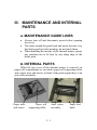
A. MAINTENANCE GUIDE LINES
•
•
•
Always turn off and disconnect power before opening
the cover.
The areas around the print head and motor become very
hot during and just after printing, do not touch them.
When handling the interior of the thermal printer, please
pay attention not to be hurt by any sharp edge of the
metal parts.
B. INTERNAL PARTS
When the top cover of the thermal printer is removed, in
paper roll compartment we can find a paper roll supporting roller
and a paper near end sensor, in front of the print engine there is an
auto cutter assembly.
Paper near
end sensor
Paper roll
supporting roller
3-1
Auto cutter
assembly
Paper feed
knob
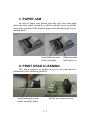
C. PAPER JAM
In case of paper jam, please open the top cover and push
down the auto cutter assembly so that it could be easier to get the
messed up portion of the thermal paper when the head-up lever is
pushed down.
Push down the auto
cutter assembly
Push down the
head-up lever
D. PRINT HEAD CLEANING
The whole process of getting access to the print head is
illustrated in the following pictures:
Start pushing the auto
cutter assembly down
All the way down to level
3-2
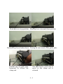
Head-up lever at up position Head-up lever at normal down position
Push head-up lever further down Freeing the movement of the guide plate
Pull the lug on guide plate
backward to release the
clamp rod
The print head is now free to
move as the clamp rod is
released
3-3
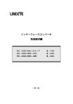
Guide slot of print head
Gently move the print head along its guide slot out (do not
damage the cabling to it and never do this when print head is
still hot), you can clean the thermal elements of the print head
using a cotton swab moistened with alcohol solvent (ethanol,
methanol, IPA)
NOTE: Do not touch the print head thermal elements
Do not scratch the print head
Before re-assuming the print head position, alcohol solvent
should be dried completely.
Thermal elements
3-4
IV. SPECIFICATIONS
A. PRINTER
ITEM
Printing method
Effective printing width
Thermal
head
configuration
Printing speed (max.)
Paper feed method
Paper feed entrance
Auto-cutter capability
Partial cut gap
Input power type
Input voltage
Power consumption
Dimension (mm)
Weight
SPECIFICATION
Thermal sensitive line dot method
72 mm
576 dots / line
80 mm / sec. @ 24 V, standard paper,
high speed
Friction auto-feed
Rear insertion
Full cut / Partial cut per software
command
Approx. 2 mm at the center
DC
24 V + / - 5 %
0.12 A @ stand by
1.25 A @ printing
4.50 A @ max.
168 (W) x 233 (D) x 127 (H)
1.4 Kg net, 2.1 Kg w/ power adaptor
B. PAPER
Paper type
Paper roll formation
Paper width
Paper roll outer diameter
Paper roll inner diameter
Thermal roll paper
External side is heat-sensitive side
80 + 0 / - 1 mm
83 mm max.
12 + 1 / - 0 mm
4-1
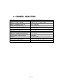
C. POWER ADAPTOR
ITEM
INPUT VOLTAGE
INPUT FREQUENCY
INPUT CURRENT
OUTPUT VOLTAGE
OUTPUT POWER
STATIC LOAD
OUTPUT REGULATION
VPP RIPPLE & NOISE
MTBF
EMI STANDARDS
SAFETY STANDARDS
REQUIREMENT
100 V AC ~ 250 V AC
50 ~ 60 HZ
1.5 A MAX.
+ 24 V DC
52 W MAX.
0 A ~ 2.2 A
+/-5%
240 mV
30,000 HRS
VDE – B, FCC – B, VCCI – B
UL, CSA, TUV, CE
4-2
V. TECHNICAL INFORMATION
A. INTERFACES
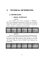
1. SERIAL INTERFACE
a.RS232
The standard serial interface applicable to PP4000S is
RS232. The communication protocols in RS232 are: 19200 bps,
none parity, 8 data bits, 1 stop bit. These settings are fixed, not for
change. The RS232 connection is done through a 9 pin D sub
female connector with following pin assignments:
Pin #
1
2
3
Definition
N.C.
TXD
RXD
Pin #
4
5
6
Definition
DTR
GND
DSR
Pin #
7
8
9
Definition
N.C.
CTS
N.C.
b.RS422
RS422 is the serial interface applicable to PP4000B. Similar
to RS232, the communication protocols in RS422 are: 19200 bps,
none parity, 8 data bits, 1 stop bit. These settings are also fixed
and not for change. The RS422 connection uses the same 9 pin D
sub female connector used in RS232 with following pin
assignments:
Pin #
1
2
3
Definition
RD+
RDCS+
Pin #
4
5
6
Definition
CSGND
SD+
5-1
Pin #
7
8
9
Definition
SDRS+
RS-
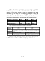
2. PARALLEL INTERFACE
The communication interface applied in PP4000C is the
Centronics parallel interface using a 25 pin D sub male connector
with the following pin assignments:
Pin #
1
2
3
4
5
6
7
8
9
Definition
-STROBE
D0
D1
D2
D3
D4
D5
D6
D7
Pin #
10
11
12
13
14
15
16
17
Definition
-ACK
BUSY
P.E.
SLCT
N.C.
-ERROR
N.C.
N.C.
Pin #
18
19
20
21
22
23
24
25
Definition
GND
GND
GND
GND
GND
GND
GND
GND
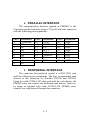
3. PERIPHERAL INTERFACE
The connector for peripheral control is a 6P6C RJ11 jack
with the following pin assignment. The best recommended cash
drawers to this connector are Posiflex CR3100 and CR3200.
Using the cable CCBLA-180 delivered with the cash drawer, the
PP4000 series can control one dedicated cash drawer. However,
by using an optional split cable CCBLA-238, PP4000 series
controls two cash drawers through this connector.
5-2
6P6C RJ11 jack
PIN #
1
Definition
FG
2
CRB
3
4
SENSE
VCC
5
CRA
6
SG
6 pin plug
Description
Frame ground
Drawer kick for cash drawer controlled by
software command Esc p 0 n1 n2
Input peripheral status
+ 24 V DC supply
Drawer kick for cash drawer controlled by
software command Esc p 1 n1 n2
Signal ground
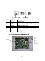
B. HARDWARE SETTINGS
JP11
JP10
JP9
U11
DIP
SWITCH
5-3
When the bottom metal plate is removed by a qualified
technician, you can see the control board from the bottom as
shown in the above picture. Please be reminded that such
operation, if not done by a qualified technician, voids the
warranty. There are 3 jumpers and 1 DIP switch as circled in
white determine the characteristics of the printer besides some
difference in components. Their functions are explained below:
Jumpers vs. interfaces
Serial RS232 interface
Serial RS422 interface
Parallel interface
JP11
1-2 short
2-3 short
Open
JP10
2-3 short
2-3 short
1-2 short
JP9
Open
Open
Short
The 4 position DIP switch works as following:
Switch
position
1
2
3
4
ON
OFF
Determined by factory setting for printer mechanism
used
Flash ROM exists
Without flash ROM
Paper cutting at self test No paper cutting at self test
The U11 is the font style memory for two byte characters. It
is different to each other of different language character set.
5-4
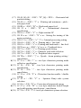
C. SOFTWARE COMMANDS
Codes (HEX / CONTROL) : COMMAND NAME
(1)
(2)
(3)
(4)
(5)
(6)
(7)
(8)
(9)
(10)
(11)
(12)
(13)
(14)
(15)
(16)
09 / <HT> : Horizontal tab
0A / <LF> : Line feed with printing
0C / <FF> : Forms feed
1B 19 n / <ESC> <EM> n : Setting the amount of the
feeding at automatic paper feed
1B 1E / <ESC> <RS> : Black - white reversed printing
specification
1B 1F / <ESC> <US> : Black - white reversed printing
cancellation
1B 21 n / <ESC> “!” n : Printing mode specification
1B 25 n / <ESC> “%” n : Download character set
specification / cancellation (valid only when optional
memory is installed)
1B 26 y c1 c2 [d]k / <ESC> “&” y c1 c2 [d]k : Download
character definition (valid only when optional memory is
installed)
1B 2A m n1 n2 [d]k / <ESC> “*” m n1 n2 [d]k : Bit image
mode specification
1B 3F n / <ESC> “?” n : External registration character
deletion (valid only when optional memory is installed)
1B 32 / <ESC> “2” : 1/6 - inch line pitch setting
1B 33 n / <ESC> “3” n : Minimum - pitch - unit line pitch
setting
1B 40 / <ESC> “@” : Printer initialization
1B 41 n / <ESC> “A” n : Line spacing setting
1B 43 n / <ESC> “C” n : Page length (number of lines)
setting
5-5
(17) 1B 44 [d]k 00 / <ESC> “D” [d]k <NUL> : Horizontal tab
position setting
(18) 1B 4A n / <ESC> “J” n : Printing and minimum - pitch unit paper feed
(19) 1B 4B n / <ESC> “K” n : Backward paper feed
(20) 1B 52 n / <ESC> “R” n : International character
specification
(21) 1B 56 n / <ESC> “V” n : Right rotation 90º
(22) 1B 58 n m / <ESC> “X” n m : Setting the turning of the
motor excitation
(23) 1B 63 31 n / <ESC> “c” “1” n : Internal processing setting
(24) 1B 64 n / <ESC> “d” n : Printing and n - line feed
(25) 1B 65 n / <ESC> “e” n : Printing and backward n - line feed
(26) 1B 70 m n1 n2 / <ESC> “p” m n1 n2 : Peripheral drive
(27) 1B 73 n / <ESC> “s” n : Printing speed setting
(28) 1B 74 n / <ESC> “t” n : Character code table selection
(29) 1B 75 n / <ESC> “u” n : Peripheral status request
(30) 1B 7B n / <ESC> “{” n : Upside - down printing setting /
cancellation
«(31) 1C 21 n / <FS> “!” n : two byte characters printing mode
collective specification
«(32) 1C 26 / <FS> “&” : two byte characters printing mode
specification
«(33) 1C 2E / <FS> “.” : two byte characters printing mode
cancellation
(34) 1C 39 n / <FS> “9” n : Detection function enable / disable
setting
«(35) 1C 43 n / <FS> “C” n : Japanese Kanji code system
selection
(36) 1C 45 n / <FS> “E” n : Correction of impressed energy
«(37) 1C 57 n / <FS> “W” n : two byte characters double height
and width printing specification / cancellation
«(38) 1C 74 n / <FS> “t” n : two byte characters system selection
5-6
(39) 1D 26 m x y1 y2 [d]k / <GS> “&” m x y1 y2 [d]k : Registration
of image data
(40) 1D 27 m n / <GS> “’” m n : Print registered image data
(41) 1D 3C / <GS> “<” : Mark detection execution
(42) 1D 41 m n / <GS> “A” m n : After - mark detection head
detection distance setting
(43) 1D 45 n / <GS> “E” n : Print quality setting
(44) 1D 56 n m / <GS> “V” n m : Paper cutting
(45) 1D 65 n m / <GS> “e” n m : Bar code width setting
(46) 1D 68 n / <GS> “h” n : Bar code height setting
(47) 1D 68 m n [d]k / <GS> “k” m n [d]k : Bar code printing
(48) 1D 77 n / <GS> “w” n : Bar code width magnification
setting
Those commands marked with « are applicable to the two
byte characters only and are not applicable to the standard
(English) models.
For detail description of the above listed commands, please
visit our web site http://www.posiflex.com.tw and look for
“PP4000 command details”.
5-7
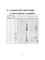
VI. CHARACTER CODE PAGES
A. PAGE 0 ENGLISH / JAPANESE
6-1
B. PAGE 1 ENGLISH / EUROPEAN
(In these tables, “SP” indicates a space.)
Note:
1. Each code is represented in hexadecimal notation.
2. If an undefined code (<00> to <1F>) or an undefined <ESC>,
<FS>, or <GS> sequence listed in this table is received, an
abnormal operation may occur. (However, when image print
6-2
data, character registration data, or command parameters are
received, they are handled as ordinary data.)
6-3