1
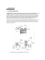
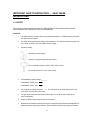
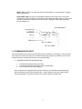
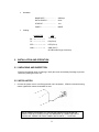
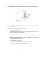
CP SERIES
User's Manual
Table of Contents
PAGE
1. INTRODUCTION
1.1 Systems Description ……………………………………………………….1
1.2 Product Specification ……………………………………………………...3
Electrical Specification …………………………………………………… 4
Mechanical Specification …………………………………………………4
Operating Environment ……………………………………………………4
Typical Battery Backup Time ……………………………………………..4
1.3 Safety ……………………………………………………………………….5
1.4 Displays and Switch ……………………………………………………….6
1.5 Communication Port ……………………………………………………….7
2. INSTALLATION AND OPERATION
2.1 Unpacking and Inspection ………………………………………………… 9
2.2 Installation …………………………………………………………………... 9
2.3 Storage Instruction ………………………………………………………….12
3. TROUBLESHOOTING
3.1 Troubleshooting Tips ……………………………………………………….12
3.2 Troubleshooting Charts …………………………………………………….13
1. INTRODUCTION
1.1 SYSTEM DESCRIPTION
The MINUTEMAN CP Series UPS is an advanced true on-line sinewave uninterruptible power system
with bypass switch. It provides reliable, regulated, transient-free AC power to your sensitive
equipment, ranging from computers and telecommunication systems to computerized instruments.
Because the UPS is an on-line design, conditioned power is provided continuously to the attached
devices. Unlike the standby UPS, its on-line structure is constantly regulating, filtering the output
power when commercial power is present. During electrical power failure, the unit employs its
internal maintenance-free battery to supply back-up power without any transfer time.
In the event of overload or inverter failure, the UPS will transfer to the bypass as an alternate source.
The UPS can transfer back to the inverter automatically after the overload condition has been
cleared. All the above transfer time is within four (4) milliseconds that can ensure your equipment
operating uninterruptedly.
Output Receptacle is optional, NEMA 5-15R or IEC 320.
1
Output Receptacle is optional, NEMA 5-15R or IEC 320.
2
1.2 PRODUCT SPECIFICATION
ELECTRICAL SPECIFICATION
ELECTRICAL SPECIFICATION
Power Rating
Model
No.
Frequency
(HZ)
Voltage
Current
Voltage
Current
CP500
60
120VAC
6.0A
120VAC
4.2A
CP500/2
50
220VAC
3.1A
220VAC
2.3A
CP1K
60
120VAC
11A
120VAC
8.3A
CP1K/2
50
220VAC
6.2A
220VAC
4.5A
CP2K/2
200VA/1400W
CP2K/2
50
220VAC
8.3A
220VAC
9.1A
CP3K/2
3000VA/2100W
CP3K/2
50
220VAC
12.0A
220VAC
13.6A
CP500
Series
500VA/350W
CP1K
Series
100VA/700W
Input
Output
NOTE: The power factor of CP2K/2 and CP3K/2 is 0.97.
INPUT
Input Frequency Range: ± 5%
Input Voltage Range: + 10%, - 15%
OUTPUT
Output Frequency Regulation: Phase lock to input under normal condition
± 0.5% at free running.
Output Voltage Regulation: ± 2%
Distortion: Less than 3% under linear load.
BYPASS TRANSFER TIME
UPS Failure: 2.5 ms typical, 4 ms max. (from inverter to bypass and vice
versa).
3
MECHANICAL SPECIFICATION
MECHANICAL SPECIFICATION
Model
No.
Dimension
W x D x H (inches)
Net
Gross
CP500
5.6 x 17.5 x 7.5
25
28
CP1K
7.5 x 17.7 x 10.4
50
56
CP2K/2
7.5 x 18.1 x 18.4
99
108
CP3K/2
7.5 x 20.7 x 19.8
120
124
OPERATING ENVIRONMENT
Weights (lbs)
Temperature: 0º C to 40º C
Relative Humidity: 0 to 95%, non-condensing.
TYPICAL BATTERY BACK-UP TIME
4
IMPORTANT SAFETY INSTRUCTION -- SAVE THESE
INSTRUCTIONS
1.3 SAFETY
This manual contains important instructions for MINUTEMAN CP series that should be followed
during installation and maintenance of the UPS and Batteries.
CAUTION:
The UPS contains voltages, which are potentially hazardous. Qualified service personnel
should perform all repairs.
The UPS has its own internal energy source (battery). The output receptacles maybe live
even when the UPS is not connected to an AC supply.
Symbol meaning:
Alternating current supply
Symbol for equipment grounding conductor.
On and standby symbol for 220V, 230V, 240V version.
On and Off symbol for 110V, 120V version.
Internal Battery supply voltage _______
UPS MODEL CP500: 24V _ _ _
UPS MODEL CP1K: 60V _ _ _
An insulated grounding conductor —— The wire shall be 18 AWG minimum PVC UL
1015 green or green with yellow strip.
The grounding conductor described in above item is to be grounded to earth at the
service equipment.
Plug the UPS into a grounded 3-wire AC receptacle.
Replacement of batteries should performed or supervised by personnel knowledgeable of
batteries and the required precautions. Keep unauthorized personnel away from battery.
5
When replacing batteries, use the same number and the following type batteries:
Matsushita (or Panasonic) Electric Works. Type LCR12V6.5P, rated 12V.
Do not dispose of battery or batteries in a fire, the battery may explode.
Do not open or mutilate the battery or batteries, released electrolyte is harmful to the skin
and eyes. It may be toxic.
A battery can present a risk of electrical shock and high short circuit current. The
following precautions should be observed when working on batteries.
Remove watches, rings or other metal objects.
Use tools with insulated handles.
For safe and continuous operation of the UPS depend partially on the care taken by user. Please
observe the following precautions:
Do not disassemble the UPS.
Do not attempt to power the UPS from any receptacle except a 2-pole 3-wire grounding
receptacle.
Do not place the UPS near water or in environment of excessive humidity.
Do not allow liquid or any foreign object to get inside the UPS.
Do not block air vents in front of the UPS or air exhausts in the back.
Do not plug appliances, such as hair dryers, into the UPS receptacles.
Do not place the UPS under direct sunshine or close to heat-emitting source.
A certified detachable power supply cord is to be used with this equipment. For a related
2
current up to 10A, a type not lighter than HO5VV-F3G 0.75mm shall be used. For
2
CP3K/2, rated current 16A, a type not lighter than HO5VV-F3G 1.5 mm shall be used.
Caution - Electric shock hazard. Battery circuit is not isolated from the input voltage.
Caution -- Electric shock hazard. Even after disconnection from the mains input
There may be hazardous voltage between battery terminals and ground. Check that
there is no voltage before touching!
voltage, components inside the UPS are still connected to the battery and are at
hazardous potential. Disconnect the battery supply circuit before carrying out servicing or
maintenance work.
1.4 DISPLAYS AND SWITCH
MAIN switch: Turn on the UPS by depressing the front panel switch into the position " | " and
turn off the UPS by depressing switch to the position "
".
LINE LED: This light means that the incoming AC line is normal.
BYPASS LED: The light means that the UPS is providing power directly from the incoming
AC line through the bypass line.
6
FAULT LED: The light is on when the UPS is in fault condition. In the meantime, the alarm
beeps continuously.
LOAD LEVEL LED: The light is a bar graph and indicates how much load is on the UPS.
The lights are in 25% increments. If the UPS is overloaded, the LED's show over 100%, then
you have connected too many devices into the UPS. Unplug the least critical equipment,
such as a printer etc.
1.5 COMMUNICATION PORT
The communication port on the back of the UPS may be connected to a computer. This port allows
the computer to monitor the status of the UPS and control the operation of the UPS in some cases.
Its major functions normally include some or all of the following:
A. COMUNICATION PORT INTRODUCTION
To broadcast a warning when power fails.
To close the files before the battery reserve is exhausted.
To turn off the UPS and the computers.
Some computers are equipped with a special connector to link with this communication port.
Some computers require a special plug-in card. Some computers may need a special UPS
monitoring software. Contact your dealer for the detail of different interface kits.
7
Pin 2: The relay will close when
input power fails.
Pin 3: The relay will become open
when input power fails.
Pin 4: Common for pins 2, 3, and 5.
Pin 5: The relay will close when the
battery inside the UPS has
less than about 3 minutes
(CP500: 1.5 minutes) of
backup time left.
Pin 6: User may send a high level
signal (+5V ~ + 12V) for
over 500 ms to turn off the
UPS. But it can only
activate when input power
fails.
PIN 7: Common for pin 6.
NOTE:
1. Relay rating +24V 0.5A
2. Pin 7 should be connected to ground only.
B. RS232 COMMUNICATION PORT INTRODUCTION (FOR CP3K/2 ONLY)
INTRODUCTION:
The RS232 communication port provides the following features:
1.
2.
3.
4.
5.
6.
Monitor charger status.
Monitor battery status and condition.
Monitor inverter status.
Monitor UPS status.
Monitor the utility status.
Provide the power switch function for computer to turn on and off the utility to the
computer on schedule for power saving.
Computer will control information exchange by a query followed by <cr>. The UPS will
respond with information followed by a <cr> or action.
UPS data will be provided at 2400 baud rate and consist of 8 data bits, 1 stop bit, and no
parity bit. All the information is provided in ASCII format.
8
Hardware:
BAUD RATE ……………… :
2400 bps
DATA LENGTH …………... :
8 bits
STOP BIT …………………. :
1 bit
PARITY ……………………. :
NONE
Cabling:
UPS
COMPUTER
RX →—- — — — —
TX (PIN 9)
TX — — — — — ≡
RX (PIN 6)
DTR — — — — — ≡
DTR (PIN 1)
GND — — — — — ≡
GND (PIN 7)
(9 PIN female D-type connector)
2. INSTALLATION AND OPERATION
2.1 UNPACKING AND INSPECTION
Examine the packing carton for damage. Notify the carrier immediately if damage is present.
Retain the packing for future use.
2.2 INSTALLATION
1. Connect the power cord to a verified-grounded 3-wire receptacle. CP3K/2 comes with locking
casters (upward for release, downward for lock).
THE AC POWER IS PRESENT AT THE OUTPUT RECEPTACLE WHEN THE
POWER CORD IS PLUGGED IN AND THE BREAKER IS TURNED ON EVEN IF
YOU DO NOT PRESS THE FRONT PANEL SWITCH INTO " | " POSITION.
9
2. Charge the batteries for ten (10) hours before use. The UPS will recharge the batteries
automatically whenever its power cord is plugged into a wall outlet. You may use the UPS
immediately without recharging, but the backup time may be less than the rating.
3. Connect the power cord of your computer equipment to the output receptacles of the UPS. Turn
on the computer equipment.
DO NOT PLUG LASER PRINTERS INTO THE UPS BECAUSE THEY DRAW TOO
MUCH POWER.
4. CP500, CP1K , CP2K/2
Turn on the UPS by depressing the front panel switch to the position " | ". The "LINE" "BYPASS"
and "LOAD LEVEL" LED's will light up. After a few seconds the "INVERTER" will light up, too.
About 25 seconds later, the "BYPASS" LED will go off. Now, the UPS is working properly.
5. CP3K/2
Turn on the UPS by depressing the panel switch to the position " | ". All LEDs on panel will light
up. Then, check load level LED one by one, and all load level LEDs flash again. After a few
seconds the "INVERTER" indicator will light up. About 25 seconds later, the "BYPASS" LED will
go off. Now, the UPS is working properly. If the "LOAD LEVEL" shows it is over 100%, buzzer
beeps twice per second. It means that you have connected too many devices to the UPS.
Unplug the least critical equipment, such as printer, etc.
10
6. To test the UPS turn OFF commercial power by either turning OFF the breaker supplying power
to the commercial receptacle, or using a switchable power strip.
7. Due to physical stability requirement for CP3K/2 series, please install the supporter to the UPS at
the bottom side with two screws.
8.
External battery pack installation for CP2K/2 and CP3K/2
Remove the top lid from both units.
Remove the side panel (left side for CP3K/2, two sides for CP2K/2) from the control unit,
and the right side panel from the battery pack.
Connect the cable (CP3K/2: Anderson connector, CP2K/2: Fastons connector to the
power stage connector marked CN15) at the control unit. Then connect Anderson
connector to the battery pack.
Slide the units together, so that bracket "A" lines up on the left side of the control unit and
on the right side of the battery pack.
Install both top lids with screws again.
Install two brackets labeled "B" between the two units at the back.
The UPS is now ready for normal start-up and check out.
11
2.3 STORAGE INSTRUCTION
For extended storage in moderate climates, the batteries should be charged for 12 hours every 3
months by plugging the power cord into the wall receptacle. Repeat it every 2 months in high
temperature locations.
3. TROUBLESHOOTING
3.1 TROUBLESHOOTING TIPS
The TROUBLESHOOTING chart covers most of the difficulties that you may encounter under normal
working conditions. If the UPS fails to operate properly, please review the following checks before
calling the repair center:
1. Is the UPS plugged into a correctly working outlet?
2. Is the line voltage within the rating specified?
3. Has the fuse on the back panel on model CP500 blown?
4. Has the circuit protector on the back panel of model CP1K or CP2K/2 tripped?
5. Has the circuit breaker on the back panel of the CP3K/2 tripped?
12
Please note the following information when you call for service:
1. Model #, Serial #
2. Date of problem
3. Full description of problem
3.2 TROUBLESHOOTING CHART
TROUBLESHOOTING CHART
PROBLEM
No light, no alarm (UPS
not ON)
POSSIBLE CAUSE
ACTION TO TAKE
Front panel switch in off position
Turn on switch
Rear panel fuse blown or circuit
protector trip
Replace fuse or reset
protector. Restart UPS.
No incoming utility
Check input power
Breaker is off
Check the breaker ON/OFF
Breaker is off
Check the breaker ON/OFF
No incoming utility
Check input power
Fuse blown or protector trip
Replace fuse or reset
protector. If problem remains
call for service
"FAULT" LED lights, alarm
beeps continuously.
UPS failure
Call for service
Backup time is less than
the rating.
Battery is not fully charged.
Charger failure
Recharge the battery for at
least 6 hours. Re-test the
backup time. If problem
remains, call for service.
"LOAD LEVEL" LED"S
show over 100%
Overloaded
Remove the least critical load.
Buzzer beat twice per
second.
Overloaded
Remove the least critical load.
No "LINE" light, alarms
beeps every few seconds.
Dead battery.
13