1
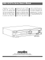
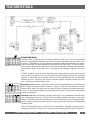
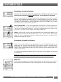
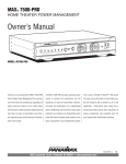
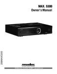
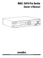
MAX 5410 Pro Series
Owner’s Manual
®
1690 Corporate Circle, Petaluma, CA 94954 • www.panamax.com
MAX 5410 Pro Series Owner’s Manual
®
Congratulations on your selection of
the MAX® 5410 as the AC power
source for your audio/video system!
Over 25 years of power protection experience and more than 10 years of
Audio/Video noise filtration engineering experience were utilized in the
development of this model. The MAX®
5410 has been specifically engineered
to enhance the performance and life
expectancy of Audio/Video entertainment gear. The combination of sophisticated noise filtration circuitry and the
world’s finest surge protection has
resulted in an Audio/Video power center that meets the power quality needs
for each piece of equipment in your
entertainment system. The styling of
the MAX® 5410 complements even the
most sophisticated Audio/Video showcase.
MODEL # M5410
PANAMAX, the Panamax logo and MAX are registered US trademarks of Panamax.
Protect or Disconnect, SurgeGate Plus and SignalPerfect are trademarks of PANAMAX.
SIDACtor is a registered US trademark of Teccor Electronics, Inc. TiVo is a trademark of TiVo, Inc.
© 2003 PANAMAX CORP. All Rights Reserved.
TABLE OF CONTENTS
Before You Begin.........................................................1
Voltage Sense Trigger Input...................................8
Introduction.................................................................2
Voltage Trigger Output...........................................8
Connection Diagram....................................................3
Circuit Breaker.......................................................8
Feature Overview.........................................................4
Coaxial Line Protection..........................................9
Feature Details
Telephone Line Protection......................................9
Front Panel Pushbutton.........................................5
AC Power Cord......................................................9
Sequential Startup/Shutdown................................5
AC Surge Protection............................................10
Diagnostic Lights.............................................5 & 6
SurgeGate Plus™ Protection................................10
Voltmeter...............................................................6
Technical Specifications.............................................11
Convenience Outlet................................................6
Contacting Panamax..................................................11
Filtered Outlet Banks..............................................7
Frequently Asked Questions.......................................12
High-Current Outlet Bank.......................................8
MAX PRO-Series RS-232 Command Specs...............13
BEFORE YOU BEGIN
Items included with the MAX® 5410:
LED Lamp
IEC 320, 120V/15A
10 ft. power cord
Rack ears w/ screws for
rack mounting option
Please verify that you have received all these items. If not, contact Panamax.
USA & Canada (800) 472-5555 • (707) 283-5900 • Fax (707) 283-5901
1
INTRODUCTION
Your Audio/Video components are constantly
being bombarded by electromagnetic interference (EMI) and radio frequency interference
(RFI) through their power cords. This contaminated power can affect A/V equipment and will
degrade the overall performance of your entire
system. Common symptoms of contaminated
power include pops, hisses, hums, visual artifacts, etc. Most power filtering devices will
remove some of this interference but don’t
provide a real solution to the problem.
The MAX® 5410 Sophisticated Filtration
System is a Real Solution!
Filtered Outlet Banks:
The primary noise filtration system features
cascaded banks of filter circuits that supply
power to the Always-On and Switched outlets.
The filtration circuitry has been specifically
designed to filter out all forms of electromagnetic and radio frequency noise in both common and normal modes. There are four banks
of outlets with two outlets per bank. Crosscontamination between the outlet banks is also
eliminated with this design.
Outlet Banks 1 and 2 are always on, providing
continuous power to those components with
programmable memory settings. Banks 3 and
4 can be set to either always on or switched. A
rear panel slide-switch provides the option of a
10 second shutdown delay if these outlets are
configured as Switched.
High-Current Outlet Bank:
The unique power requirements of current
hungry components such as amplifiers and
powered subwoofers are also addressed.
These components can rapidly draw large
amounts of current to replenish their power
supply capacitors after thunderous bass notes.
Line conditioners that utilize coils (inductors)
in series with the AC power line can “choke”
off this large inrush current, thereby reducing
the amplifiers’ ability to operate at peak
performance levels, resulting in a flat, dead
sound. The MAX ® 5410 high-current outlets
are fed by noise filtration circuitry that does
not utilize coils and provides full, unimpeded
power for your amplifiers and powered subwoofers.
As you read through the rest of this manual,
you’ll discover many more unique features.
As audiophiles, we care about the quality of
your listening and/or viewing experience.
Our goal is to:
• Provide clean pure power
• Protect your investment
• Enhance the pleasure you get from you’re
A/V system
Thank you for choosing Panamax for your
power quality needs. Please finish reading
the instructions, install your MAX ® 5410 and
enjoy the full potential of your entertainment
system.
Other Features Enhance the
Functionality:
Although the MAX ® 5410 functionality revolves
around noise filtration and power protection,
many other exciting features enhance the overall
entertainment experience, including:
• A backlit analog voltmeter indicates the AC
line voltage coming into your system.
• A combination ON/OFF/Dimmer switch
controls the meter lighting.
• An always-on, convenience outlet on the
front panel for temporary AC connections.
• Sequential start-up and shut-down of your
system using an A/V receiver (or other
component) and the 12VDC trigger input.
• 12V Trigger Output with selectable output
delay.
• RS232 Control for interfacing to automation
systems.
2
1690 Corporate Circle, Petaluma, CA 94954 • www.panamax.com
CONNECTION DIAGRAMS
STEP 1
Typical AC Power, RS232 and 12V Trigger Connections
STEP 2 Basic Signal Line Connections
USA & Canada (800) 472-5555 • (707) 283-5900 • Fax (707) 283-5901
3
FEATURE OVERVIEW
Front Panel Pushbutton:
1 of 2 Triggers that can activate a
turn-on or shutdown sequence for
Outlet Banks 1 and 2 and HighCurrent outlets.
LED:
Indicates ON/OFF
status. Flashing
indicates Turn
ON/OFF sequence
in progress.
LED Indicators:
Status indicator lights for:
• DC Voltage Trigger
• Switched Outlets
• Ground OK
• Line Fault
• Unsafe Voltage
High-Current Outlet Bank:
Two delayed outlets designed
for high-current components
such as amplifiers and powered subwoofers. The current
available to connected equipment is not limited by the
noise filtration components.
Filtered Outlet
Banks 1 and 2:
Four switched outlets for
audio/video components
that do not require constant power.
See the Featured Details section for more information.
15A Circuit Breaker:
Opens in the event that
equipment plugged into
the MAX® 5410 draws
too much current. When
the white button of the
breaker is visible, the
breaker has opened.
Reduce the load and
push to reset.
1
IEC Main Power
Receptacle:
Power cord connects
to this receptacle.
4
Ground Lug: Provides
a common grounding
point for equipment with
separate ground leads.
2
Voltage Sense
Trigger Input:
3.5mm Mini-Plug jack.
Connect to a remote trigger
device that provides 12VDC
to trigger a startup/shutdown
sequence. This is the sec ond trigger that will activate
the MAX ® 5410 turn-on or
shutdown sequence. (See
pushbutton on front panel).
Meter Light Dimmer:
Controls brightness
of the Voltmeter
backlighting.
Voltmeter:
Backlit analog meter
measures incoming
voltage source from
0-150 VAC.
Filtered Outlet
Banks 3 and 4:
Four Always-On outlets for
audio/video components that
require constant power to
maintain programmed settings.
3
Voltage Sense
Trigger Output:
3.5mm Mini-Plug jack.
Supplies a 12VDC
trigger to control
the startup/shutdown
of an additional device.
RS232
Connection:
For home
automation
systems.
Convenience Outlet:
Provides a quick convenient
way to plug in components
such as camcorders and
video game systems.
USB Style
Port for
LED
Light
Satellite
Coax Jacks:
Two pairs of gold
plated F-Connectors
optimized for
Satellite TV signal
line protection.
Cable TV
Coax Jacks:
Two pairs of gold
plated F-Connectors
optimized for Cable
TV and non-amplified
Rooftop Antenna
signal line protection.
4
Input
Trigger
Enable
Switch
Output
Trigger
Delay
Switch
High-Current
Outlets Turn-On
Switch:
2-position slide
switch. Allows
adjustment of the
Turn-On delay for
the two High-Current
Outlets. Choose
between 0 and 10
seconds.
Outlet Banks
1 and 2 Turn-Off
Switch:
2-position slide
switch. Allows
adjustment of the
Turn-Off delay for
Outlet Bank 1.
Choose between
0 and 10 seconds.
1690 Corporate Circle, Petaluma, CA 94954 • www.panamax.com
Telephone Jacks:
In/Out connections
for telephone line or
pay-per-view line
protection. Integrated
lone splitter allows
two devices to be
connected to one
phone line.
FEATURE DETAILS
Front Panel Pushbutton
This button controls the “High-Current” and “Switched” outlets.
Sequential Startup/Shutdown Complex audio/video systems may be susceptible to voltage transients generated internally at start-up/shutdown if all of the equipment is powered on or off at the same time. This can cause speaker “thumps”
which are not only annoying but can also damage the speakers. The MAX® 5410 is designed to eliminate these transients
by providing a “start-up” delay for the High-Current outlets and a “shutdown” delay for Outlet Banks 1 and 2. This allows
the components plugged into the switched outlets to power-up and stabilize before any amplifiers and powered sub-woofers
are turned on. This sequence is reversed during shutdown. The amplifiers and powered sub-woofers turn off, their power
supplies drain, then the equipment plugged into Outlet Banks 1 and 2 is turned off.
Information on setting the delay times is included in the Filtered Outlet Bank and High-Current Outlet Bank sections that
follow.
1. Press and hold switch > 2 seconds to turn the High-Current and Switched Outlets on or off.
2. When button is pressed quickly (<2 sec.) SWITCHED and HIGH CURRENT outlets turn off for 10 seconds then turn
back on in a sequence (per delay settings).The purpose is to cycle power to equipment that locks up.
Diagnostic Lights
The MAX® 5410 is loaded with special features to save your connected equipment from many different forms of dangerous
power disturbances. Six diagnostic lights on the front panel inform you in the event of a power disturbance or when a special feature is activated. The indicators are:
Power Led: Green LED indicates On/Off status. When flashing, indicates sequence in progress.
DC Voltage Trigger: Green LED. This light indicates status of the DC voltage trigger on the back panel of the MAX®
5410. The light is ON when the DC voltage trigger is activated and OFF when the DC voltage trigger is not receiving a signal.
This light will also be ON if nothing is plugged into the DC voltage trigger input jack. This indicates that the DC voltage trigger
is being bypassed.
Switched Outlets: Green LED. This light indicates the status of the “Switched Outlets” pushbutton on the front panel
and corresponds with the switch position. When the button is in the “ON” position, the light is ON. When the button is in
the “OFF” position, the light is OFF. “Switched Outlets” refers to Outlet Bank 2 and the High-Current Outlets. See their
respective sections for switching options.
USA & Canada (800) 472-5555 • (707) 283-5900 • Fax (707) 283-5901
5
FEATURE DETAILS
(Diagnostic Lights Continued)
Ground OK: Green LED. When this light is ON, it indicates that the wall outlet is properly wired. When the light is OFF,
it indicates that the wall outlet has a reversed line and neutral wire, or that there is no ground present.
Line Fault: Red LED. When this light is ON, it is indicating that the wall outlet has a reversed line and neutral wire, or
there is no ground present. This light will remain OFF if the wall outlet is properly wired.
Unsafe Voltage: Red LED. Under normal voltage conditions, this light stays OFF. When this light is FLASHING slowly (once per second), it indicates an undervoltage (<95 VAC) or overvoltage (>134 VAC) condition. When the light is flashing quickly (4 times per second), it indicates a 10 second recovery period from an under/overvoltage condition. This light
will flash quickly when the MAX ® 5410 is first plugged into the wall outlet.
Meter Light Control
Controls the brightness level, or turns the lighting off altogether.
Voltmeter
The analog Voltmeter is backlit to provide the ability to view the reading in a dark room. LEDs (light emitting diodes) are
used as the light source in order to provide durability and long life. The “Meter Light” dimmer controls the brightness level,
or turns the lighting off altogether.
The Voltmeter monitors the incoming voltage from the wall receptacle and provides a visual representation of the available
power. The voltmeter is ALWAYS-ON and indicates the incoming line voltage even during an unsafe voltage condition.
Readings above 150VAC will not be accurate due to the meter’s damping characteristics.
Convenience Outlet
A single outlet on the front panel of the MAX® 5410 provides an easy to reach power source for electronic equipment typically used on a part time basis. Such equipment includes anything from video game systems to camcorders.
The convenience outlet not only provides superior surge suppression, but also taps into Filter Circuits to provide clean power
for your sensitive electronic equipment. This outlet is an Always-On outlet and will continually supply a steady source of
power for your connected equipment. It is important to remember that power will be disconnected only in the event
of an unsafe voltage condition.
6
1690 Corporate Circle, Petaluma, CA 94954 • www.panamax.com
FEATURE DETAILS
Filtered Outlet Banks
Eight Outlets (4 banks / 2 outlets per bank) are fed through cascaded noise filtration circuits. These circuits are designed to
eliminate AC contamination that is detrimental to the performance of audio or video components like stereo receivers, VCRs
or televisions. The dedicated filters are carefully engineered to provide power filtration and inter-component "noise isolation"
for both “common-mode” (line/neutral to ground) and "normal-mode" (line-to-neutral) EMI/RFI. This means that high-frequency interference will be drastically reduced not only from the incoming power but also from equipment plugged into the
other outlet banks, regardless of what "mode" it occurs in. Even equipment with ungrounded, 2-blade plugs, receives clean
power.
As shown in the diagram, there are four banks of filtered outlets (not counting the High Current outlets and the front panel
convenience outlet). Cascaded filter circuits are used to feed the various banks and provide maximum noise isolation and
attenuation. All 4 banks benefit from the inductorless input filter, the Common Mode Balanced L filter and Normal Mode
Balanced L filter circuits. Outlet banks 2 and 4 receive their clean power through this comprehensive network of filters while
banks 1 and 3 benefit from additional Balanced L filters.
1
2
Outlet Banks 1 and 2 contains four switched outlets that will turn your connected equipment ON or OFF with one of two
MAX® 5410 triggers front panel push-button or Voltage Sense Trigger. A 2-position slide switch located on the rear panel
controls the timing. Together, these outlets can be set as Always-On or with a turn-off delay of 10 seconds to prevent speaker "thump". This switch provides the option of having a total of eight always-on outlets. See the Sequential Startup/Shutdown
section for more information.
3
4
Outlet Bank 3 and 4 remain ON continually to provide a constant power source for programmable audio/video components. A personal video recorder (such as TiVo™) and VCR are two examples of components that require a constant supply
of power. A TiVo™ video recorder relies on continual power to monitor the cable signal and retain its programmed information. A VCR should be connected to one of these always-on, filtered outlets to maintain correct clock time and programmed
recording information.
When set to 10 second delay position, these outlets will remain as Switched outlets, controlled by the front panel push-button and/or the DC Voltage Sense Trigger. In this situation, these outlets will not power down until after the selected time has
USA & Canada (800) 472-5555 • (707) 283-5900 • Fax (707) 283-5901
7
FEATURE DETAILS
High-Current Outlet Bank
The two high-current outlets allow amplifiers and powered subwoofers to work to their full potential. When the movie thunders with a terrific explosion or when the music reaches a climactic crescendo, an amplifier has to rapidly draw large amounts
of current to replenish its power supply capacitors. Traditional line conditioners impede this current draw, in effect, starving
an amplifier and resulting in a flat, dead sound. The High-Current Outlet Bank provides clean, filtered power to amplifiers
but has no current limiting components to impede performance.
The high-current outlets are designed with a turn-on delay option of 0 or 10 seconds. The 2-position, Delayed Outlet TurnOn Switch on the back of the MAX® 5410 is used to select the desired time delay. When a delay is selected, the high-current outlets will turn-on after Outlet Banks 1 and 2 and turn-off before Outlet Banks 1 and 2 (if they’re not set to Always-On).
With a delay, the connected equipment will not power up simultaneously, thus preventing loudspeaker noises such as
“thumping”. See the Sequential Startup/Shutdown section for more information.
Voltage Sense Trigger - DC Triggers
Input Trigger - This feature provides an ON/OFF trigger for the MAX® 5410 using a DC remote control signal. Many components such as pre-amplifiers and receivers have a 12VDC trigger built-in, and will transmit a constant power signal when
turned on and in use. This power signal will initiate the startup or shutdown sequence of the MAX® 5410’s switched and
high current outlets. An AC adapter of the appropriate voltage, plugged into a switched outlet on the receiver, may also be
used if a 12V trigger is not built in. The MAX® 5410 voltage sense trigger input uses a standard 3.5mm mini-plug jack.
Please note: The front panel pushbutton must be left in the “ON” position if you are using the DC Input Trigger and not
connected to a Home Automation system through the RS232 port.
Input Trigger Enable Switch – This switch is used to disable or enable the Input Trigger feature. The circuitry for the voltage sense trigger also controls the Voltage Trigger Diagnostic LED on the front panel. When disabled, the front panel Trigger
LED remains lit and the front panel pushbutton controls the ON/OFF state of the switched and high current outlets.
When enabled, and a DC voltage is sensed by the Input Trigger circuitry, the front panel Trigger LED will light to indicate that
the voltage sense circuit is ON and the MAX® 5410’s switched outlets are ON.
Output Trigger – The MAX® 5410 is capable of generating its own 12VDC remote signal to control other components. In
its default state, this output turns ON when the Input Trigger receives a signal and OFF when the input trigger signal is turned
off. This output also uses a standard 3.5mm mini-plug jack.
Output Trigger Delay Switch – This switch allows the selection of 0 or 10 second delay in turning on the 12VDC output
signal. There is no delay when it turns off.
RS232 Trigger Control – The MAX® 5410’s command set default is “ATTACHTRIG” - refer to page 13 - (Trigger Attached),
meaning that the ON/OFF state of the Output Trigger is dependent on the Input Trigger. When connected to a Home
Automation system through the RS232 port, operation of the Output Trigger can be divorced from the Input Trigger and the
automation system can control the ON/OFF state of the Output Trigger. This is accomplished through the “DETACHTRIG”
(Trigger Detached) command.
Circuit Breaker
A circuit breaker is located on the back panel of the MAX®5410. The circuit breaker will trip only if the total current draw
exceeds the maximum current rating (15A). This means that collectively, all outlets must draw more than 15 Amps before
the circuit breaker will trip.
8
1690 Corporate Circle, Petaluma, CA 94954 • www.panamax.com
FEATURE DETAILS
SignalPerfect™ Coaxial Line Protection
All coaxial cable sheaths from outdoors must be grounded to the building grounding electrode system
where they enter the building (per applicable NEC/CEC code). A driven ground rod is not adequate.
Panamax’s exclusive SignalPerfect™ Technology provides application-specific protection for your satellite and cable TV
equipment. Two lines of protection are provided for each type. The satellite connections are for coaxial cables connected to
a DBS (single or dual LNB) satellite dish. The antenna connection is for a non-amplified rooftop antenna or cable TV line.
The Additional TV connection protects the equipment plugged into the MAX® 5410 from “backdoor” surges in situations
where the video signal runs to another room for a downline TV.
Cable TV (Including HDTV) – TV tuners operate at approximately 10 millivolts (0.01 V) and utilize the frequency spectrum of 50Mhz to 950Mhz. The clamping level of the MAX® 5410’s cable TV protection circuitry is 700 millivolts (0.7 volts).
That’s less than 1 volt above normal operating levels. The circuitry is shielded to prevent interference and has been optimized to have less than 1dB of signal loss throughout the entire 50Mhz to 950Mhz range.
Satellite - Satellite dish LNB’s can require up to 24 volts to operate and utilize the frequency range of 950Mhz to 2.2Ghz.
The clamping level of the MAX ® 5410’s satellite protection circuitry is 27 volts - just 3 volts above the maximum operating
voltage. The circuitry is shielded to prevent interference and has been optimized to have less than 1dB of signal loss
throughout the entire 950Mhz to 2.2Ghz range.
SignalPerfect™ Telephone Line Protection
Satellite TV receivers require a telephone line connection for Pay-Per-View services. The MAX® 5410 also provides surge
protection for this line. The circuitry utilizes auto-resetting PTCRs and solid-state SIDACtors™ for reliability and unsurpassed protection. The clamping level of the MAX® 5410’s telephone protector is 260 volts. This will allow typical ring
voltage (90-130VAC) and operating battery voltage (-48DC) to pass through the circuit and still protect the modem in your
satellite receiver from damage.
RJ-11 phone jacks are provided for this protection. A built-in line splitter allows 2 separate components to be connected to
the same phone lines.
Please note: The protection circuitry will not work if the phone lines are reversed. The incoming phone cable must be
connected to the "LINE" jack and the cable to the audio/video equipment must be connected to the "EQUIP" jack.
Power Cord
The MAX® 5410 comes equipped with a UL recognized, 10 foot, IEC320 power cord rated for 120V, 15-Amps, minimum 14
gauge wire and the cord secured to the enclosure with a cord retention bracket. The cord is not intended to be removed.
USA & Canada (800) 472-5555 • (707) 283-5900 • Fax (707) 283-5901
9
FEATURE DETAILS
The MAX® 5410 provides protection against common problems on the AC power line. This includes spikes/surges and
sustained overvoltages or undervoltages. Panamax’s exclusive Protect or Disconnect™ circuitry is designed to protect
against spikes/surges while the SurgeGate Plus™ circuitry is for sustained over/under voltage protection.
Protect or Disconnect™ AC Surge Protection
When the MAX ® 5410 is subjected to a high voltage surge, its voltage output is limited to a safe level and the high levels
of surge current are diverted away from the connected equipment.
1. Voltage reaches an unsafe level.
2. If surge is greater than MAX ® 5410
capacity, it disconnects.
• When subjected to a 6,000V (open circuit voltage) / 500A (short circuit current) surge, the MAX® 5410 limits
its voltage output to less than 330V peak, UL’s lowest rating. The MAX® 5410 will withstand, without damage, multiple 12,000A surges, far exceeding the UL maximum requirement of only 3,000 Ampere surges.
• If the magnitude of the surge is greater than the capacity of the surge protection components, the MAX®
5410’s Protect or Disconnect™ Circuitry will disconnect your equipment in order to protect it. The MAX®
5410 will need to be repaired or replaced by Panamax if this occurs. (See Product Warranty).
SurgeGate Plus™ Protection
The MAX® 5410 constantly monitors the AC line voltage for unsafe voltage conditions such as prolonged overvoltages and
undervoltages (brownouts). These unsafe conditions pose a very dangerous threat to all electronic equipment within the
home. If the MAX® 5410 senses an unsafe power condition, it will automatically disconnect your equipment from the
power to protect equipment from damage. Once the voltage returns to a safe level, the MAX® 5410 will automatically
reconnect the power.
1. Voltage reaches an unsafe high
level and the SurgeGate Plus™
disconnects.
2. Voltage reaches a safe level and
SurgeGate Plus™ automatically
reconnects.
3. Voltage reaches an unsafe low level
and SurgeGate Plus™ disconnects.
4. Voltage reaches a safe level and
SurgeGate Plus™ automatically
reconnects.
If the line voltage exceeds the overvoltage threshold (134VAC) or falls below the undervoltage threshold (95VAC), the
MAX® 5410 will perform the following tasks until line voltage returns to a safe level:
1. Disconnects power to all connected equipment.
2. Unsafe Voltage LED is activated and will blink once per second during the unsafe voltage condition.
The MAX® 5410 requires line voltage to return to within the safe operating range for 10 seconds before returning to normal
operating mode. This is referred to as “Over/Undervoltage Recovery”. The safe operating range is considered 5V above the
under-voltage threshold (~100V) and 5V below the overvoltage threshold (~129V). Once this safe operating range is
reached, the MAX ® 5410 will perform the following functions:
1. Unsafe Voltage LED will blink 4 times per second for Over/Undervoltage Recovery.
2. Power is restored to all connected equipment after the 10-second delay. The normal start-up sequence
as determined by the “High-Current Outlets Turn-On Switch” and “Outlet Bank 2 Turn-Off Switch” will
be followed.
10
1690 Corporate Circle, Petaluma, CA 94954 • www.panamax.com
TECHNICAL SPECIFICATIONS
GENERAL
DC TRIGGER OUTPUT
Dimensions..........................17” W x 12” D x 3.5” H, (4.1” Including Feet)
Weight.............................................................................................15 lbs.
Connection........................................................................3.5mm mono mini-plug
Voltage...............................................................................................±12VDC ±2V
Current........................................................................................................350mA
AC CIRCUIT
DC TRIGGER INPUT
NOISE FILTRATION:
Connection........................................................................3.5mm mono mini-plug
Filtered Outlet Banks 1 & 3.............................................100 dB (100 KHz - 1 MHz)
Voltage and Polarity............................................3-18VDC nominal, bi-directional
Filtered Outlet Banks 2 & 4..............................................90 dB (100 KHz - 1 MHz)
Current Requirement.....................................................................................25mA
High-Current Outlets.......................................................60 dB (100 KHz - 1 MHz)
SATELLITE CIRCUIT
SURGE PROTECTION:
UL 1449 Surge Suppression Rating................................................................330V
Protection Modes....................................................................... L - N, L - G, N - G
Initial Clamping Level..........................................................200V Peak, 141V Rms
Clamping Level................................................................................................27V
Attenuation...............................................................<1 dB from 950MHz - 2.2GHz
Shielded...........................................................................................................YES
Connections......................................................................Gold plated, Female “F”
Response Time...............................................................................................<1ns
ANT/CATV CIRCUIT
Joule Rating........................................................................................2325 Joules
Clamping Level...............................................................................................0.7V
Peak Impulse Current...............................................................................91,000A
Attenuation..................................................................<1 dB from 5MHz -950MHz
Catastrophic Surge Circuit ..............................................................................YES
Shielded...........................................................................................................YES
Connections......................................................................Gold plated, Female “F”
AC:
TELEPHONE CIRCUIT
Line Voltage...............................................................................................120VAC
Clamping Level..............................................................................................260V
Max Current Rating......................................................................15A (1800 Watts)
Capacitance......................................................................................30pf (approx.)
Thermal Fuse...................................................................................................YES
Suppression Modes...........................................................Metallic & Longitudinal
Over/Under Voltage Protection.........................................................................YES
Wires Protected....................................................................2 wire/ 1 pr. (pins 4,5)
Over-voltage shutoff threshold..................................134±4 VAC, 10 Milliseconds
Fuseless/Auto-Resetting..................................................................................YES
Under-voltage shutoff threshold...............................95±4 VAC, 500 Milliseconds
Connections..................................................................................................RJ-11
Design and specifications subject to change without notice due to product improvement.
CONTACTING PANAMAX
For product and warranty information, dealer information, and other general information contact Customer Relations at:
• Email: [email protected]
• www.panamax.com
• Fax 707-283-5901
• 800-472-5555 or 707-283-5900, 7:30 a.m.- 4:30 p.m. PST
USA & Canada (800) 472-5555 • (707) 283-5900 • Fax (707) 283-5901
11
FAQs
My MAX® 5410 power cable does not
reach the wall outlet. Can I use an
extension cord to make it reach?
Yes, but you must use only Panamax extension
cords to keep your warranty valid. Ask for part
# GEC1410. (10 feet long) or
#P12X10NEMA5-15.
Can the MAX ® 5410 be included in an
equipment rack?
The included rack-mount kit allows you to
mount the unit in a standard 19" rack. The kit
includes both brackets and screws.
The provided coax or telephone jumper
cables are not long enough to reach my
equipment. Can I use other cables?
Yes, any length cable of the same type meets
the warranty requirements.
Outlet Bank 1 & 2 is not switching ON or
OFF with the MAX ® 5410. How can I fix
this?
These outlets may be set as either switched or
Always-On outlets. The 2-position, Turn-Off
Delay switch on the back panel controls this.
Change the setting of this switch from AlwaysOn to a delayed setting. This will allow these
outlets to become switched outlets.
12
The MAX® 5410 is ON but the Voltmeter
is not lit up. What is the problem?
Check the Meter Light Dimmer control to see if
the lighting is turned ON or OFF. If the control
knob is turned OFF, turn it ON and continue
turning until you have reached the desired light
level. If the control knob is turned ON and
there is no light, turn the knob to maximum.
If you still have no light, call Panamax
Customer Service for help.
There was a lightning strike in my
neighborhood and now my MAX® 5410
won’t turn on. What is wrong?
The Protect or Disconnect™ circuitry has done
its job and protected your equipment from the
lightning by sacrificing itself. Your MAX ® 5410
will need to be repaired or replaced. Please
refer to the preceding section on “Contacting
Panamax” or the warranty documentation for
more information.
What is the difference between a Surge
and Spike?
A spike is a high-energy pulse of electricity that
lasts for short periods of time (a few milliseconds, 0.001 second) but can reach up to 6000
volts or higher. Nearby lightning strikes and
ESD (Electrostatic Discharge) are the cause
for most power spikes. A surge is similar to a
spike, but will last for longer periods of time
(15 milliseconds to 2.5 seconds) and reach up
to 500 volts. Utility grid switching and motors
turning on or off cause most power surges.
Both surges and spikes are damaging to
sensitive solid-state components present
in Audio/Video equipment.
What is the difference between an
Overvoltage and Undervoltage?
An overvoltage happens when power rises
to an unsafe level (over 150 volts) for a long
period of time (2.5 seconds to several hours).
Overvoltages are usually caused by car accidents involving power poles, construction
wiring accidents, wind and ice storms. An
undervoltage (brownout) happens when power
drops to an unsafe level (under 80 volts) for a
long period of time (2.5 seconds to several
hours). Undervoltages are usually caused by
failures in the electric utility system or by very
heavy power demands during a hot day. Both
overvoltages and undervoltages will damage
Audio/Video equipment power supplies.
What Does EMI and RFI stand for?
RFI (Radio Frequency Interference) and EMI
(Electromagnetic Interference) refer to high
frequency signals emitted through the air and
induced into AC power lines. Audio/Video
equipment will pick up these signals and
generate enough noise to degrade picture
and sound quality.
1690 Corporate Circle, Petaluma, CA 94954 • www.panamax.com
MAX PRO-SERIES RS-232 COMMAND SPECIFICATIONS
1. OVERVIEW
The Panamax Pro-Series product family has a RS232 interface that allows it to communicate with a wide variety of equipment.
The purpose of this document is to outline the command set used to communicate with the Pro-Series (PS) products.
Commands and responses are in the form of ASCII character STRINGS TERMINATED
with ASCII 13, line feed (ASCII 10) or NULL (ASCIØ).
2. CONTROLLER COMMANDS
The following are commands made by the controller to Pro-Series products.
Command String
Description / Response
2.1
POWERON
Changes the front panel button status to
ON. Initiates a power-on sequence if the
previous state is OFF.
2.2
POWEROFF
Changes the front panel button status to
OFF. Initiates a power-off sequence if the
previous state is ON. (Default)
2.3
CYCLESW
Initiates a power cycle sequence for the
Switched Outlets only.
2.4
CYCLEHC
Initiates a power cycle sequence for the
High Current Outlets only.
2.5
CYCLE
Initiates a power-cycle sequence. Switched
& high-current outlets turn off, followed by
a 10 second delay, followed by a power-on
sequence.
2.6
ALLOFF
Turns off all outlets. Forces front panel
button status to OFF.
2.7
DETACHTRIG
Disconnects 12V trigger output from 12V
trigger input
2.8
ATTACHTRIG
12V trigger input passes through to 12V
trigger output (Default)
2.9
TRIGOUTLO
Forces the 12V trigger output to 0V. Does
not work when trigger is attached to 12V
trigger input.
2.10
TRIGOUTHI
Forces the 12V trigger output to 12V. Does
not work when trigger is attached to 12V
trigger input.
Command String
Description / Response
2.13
?TRIGSTAT
Request the status of the 12V trigger input. PS responds with:
a) 12VINHI if voltage is sensed on the12V input
b) 12VINLO if 0V is sensed on the 12V input
c) BUTTONON if the ON/OFF button status is ON.
d) BUTTONOFF if the ON/OFF button status is OFF.
e) 12VOUTHI if the trigger output is ON (+12V)
f) 12VOUTLO if the trigger output is OFF (0V)
2.14
?OUTLETSTAT
Request the status of the outlet banks. PS responds with:
a) MAINACON if all outlets (main relay) are ON
b) MAINACOFF if all outlets are OFF
c) SWITCHEDON if the switched outlets are ON
d) SWITCHEDOFF if the switched outlets are OFF
e) HICURRENTON if the high-current (delayed) outlets are ON
f) HICURRENTOFF if the high-current outlets are OFF
2.15
?PWRSTAT
Request the status of the input voltage
a) NORMAL if the voltage is within limits
b) OVERVOLTAGE if the voltage is greater than 132VAC
c) UNDERVOLTAGE if the voltage is less than 95VAC
d) RECOVERY if recovering from an over/undervoltage state but
has not yet restored power to outlets.
2.18
?ID
Request that the unit identify itself. Returns the following:
PANAMAX: MAX 5410
FW: SFW5410
REV: revision
2.19
HELP
All commands and queries listed above are transmitted.
USA & Canada (800) 472-5555 • (707) 283-5900 • Fax (707) 283-5901
13
USA & Canada (800) 472-5555 • (707) 283-5900 • www.panamax.com
INS5410 REV. A