1
T
ECHNICAL INFORMATION
Models No.
Description
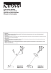
PRODUCT
P 1/ 14
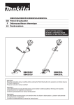
EM2650UH/ EM2650LH,
EM2651UH/ EM2651LH
Petrol Brushcutter
W
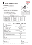
CONCEPT AND MAIN APPLICATIONS
H
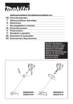
These four 25.4mL Petrol Brushcutters have been developed as
the successor models of EBH252U/EBH252L and EBH253U/EBH253L
equipped with 24.5mL 4-stroke engine.
Their main feature is the multi-position engine lubrication system.
This unique system enables the engine to be inclined to any angle
even during continuous operation with no emission of white smoke
and smell of burning engine oil for wider application range of the
brushcutters.
EM2651UH and EM2651LH additionally feature rapid start.
EM2650UH and EM2651UH are Bike handle models.
EM2650LH and EM2651LH are Loop handle models.
Engine oil
Carburetor
Starting system
Fuel tank capacity: L (oz)
Spindle thread size
Primer pump
Clutch
Handle style
Rapid start
Waist cushion
Net weight*4: kg (lbs)
EM2650UH
EM2650LH
L
EM2650UH
EM2651UH
L
EM2650LH
EM2651LH
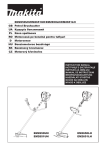
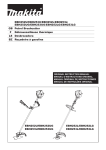
Dimensions: mm (")
Model No. EM2650UH EM2650LH
EM2651UH EM2651LH
Length (L)
1,765 (69-1/2)
Width (W) 620 (24-3/8)
330 (13)
Height (H)
Specification
Model
Specifications
Type
Displacement: mL (cu.in.)
Engine Fuel
Max. output: kW
Max. torque: N.m
No load speed*2: min.-1 = rpm
H
W
474 (18-5/8)
EM2651UH
264 (10-3/8)
EM2651LH
4-stroke
25.4 (1.5)
Straight unleaded gasoline*1
0.77 [at 7,000 min-1]
1.1 [at 5,500 min-1]
7370
6,630
7370
6,630
SAE10W-30 oil
in the Class SF or higher of API Classification
Diaphragm
Recoil starter, with mechanical decompression
0.6 (20.3)
M10, Left-handed
Yes
Yes
Bike handle*3
Loop handle
Bike handle*3
Loop handle
No
No
Yes
Yes
No
No
Yes
No
5.5 (12.1)
5.1 (11.2)
5.6 (12.3)
5.2 (11.4)
*1 Brazil: 25E gasoline
*2 No load speed of the cutting tool
*3 Of asymmetrical design
*4 Dry weight, without universal guard, cutting tool and shoulder harness
Standard equipment
Cutting tool ......................................................................................... 1
Universal guard (=Protector) ............................................................. 1
Shoulder harness with double shoulder straps ................................... 1 (for EM2650UH, EM2651UH)
Shoulder harness with single shoulder strap ...................................... 1 (for EM2650LH, EM2651LH)
Socket wrench .................................................................................... 1
Hex wrench (for M4) ......................................................................... 1
Hex wrench (for M5) ......................................................................... 1
Wire clamp (for tying cables) ............................................................. 2 (for EM2650UH)
Oil bottle without oil or Oil bottle containing 80mL engine oil ......... 1
Accessory bag .................................................................................... 1
Note: The standard equipment for the tool shown above may vary by country.
Optional
accessories
Metal blades [230mm (9") 3-tooth, 4-tooth, 8-tooth], Nylon cutting heads [Ultra auto 4, Bump & feed 4,
Bump & feed Z5], Gardening attachments (for EM2650LH, EM2651LH)
P 2/ 14
Repair
CAUTION: Repair the machine in accordance with “Instruction manual” or “Safety instructions”.
[1] NECESSARY REPAIRING TOOLS
Code No.
1R004
1R006
1R028
1R031
1R033
1R045
1R127
1R171
1R247
1R282
1R286
1R291
1R364
1R366
Description
Retaining ring pliers ST-2 for External ring
Retaining ring pliers ST-2 for Internal ring
Bearing setting pipe 20-12.2
Bearing setting pipe 28-20.2
Bearing setting plate 10.2
Gear extractor (large)
Air density tester
T-type hex. wrench 4-130
Round bar for arbor 20-100
Round bar for arbor 8-50
Round bar for arbor 12-50
Retaining ring S and R pliers
Flywheel puller
Feeler gauge set
Hex socket bit 13
Wire brush
M10-17 Hex. nut
Use for
removing/ assembling Retaining ring
removing/ assembling Retaining ring R-24
Pressfitting Spiral bevel gear 14 (the component of Cutter shaft set)
removing Spiral bevel gear 14 (the component of Cutter shaft set)
removing Cutter shaft set
removing Ball bearing 6001LLU
diagnosing Carburetor
removing / assembling M5 Hex socket head bolt
removing Clutch drum
removing Spiral bevel gear 14 (the component of Cutter shaft set)
pressfitting Clutch drum
removing / assembling Retaining rings
removing Flywheel
Adjusting Ignition coil, Spark plug and Rocker arm assembly
removing / assembling Flywheel
making Spark plug clean
removing Cutter shaft set
[2] HANDLING OF GASKET
When Gasket is removed:
(1) clear something that is sticking on the matching portions with Gasket.
(2) replace Gasket with the new one.
[3] LUBRICANT / ADHESIVE APPLICATION
Apply Makita grease N No.2 to Spiral spring in Recoil starter and the spline ends of Shaft.
When cleaning the inside of Gear case, apply 40g Makita grease N No.2 into Gear case.
When disassembling the engine, put ThreeBond 1216 to the matching surface of Crank case and Cylinder block. (Fig. 61)
[4] DISASSEMBLY/ASSEMBLY
[4]-1. Warning
Obey the following instructions in advance before repairing.
• Wear gloves.
• Keep the cover on the blade other than a trial of engine running.
• Cool down engine enough, as the engine just after used may cause you to get burned.
• Remove the remaining fuel in Tank and Carburetor completely.
• Repair the engine on the stable workbench and in the clean workplace to prevent dust and debris from entering.
• Record where and how the parts are assembled, and what are the parts. Do not reassemble them wrongly.
It is recommended to prepare the several kind of boxes to keep parts group by group.
• Treat the disassembled parts carefully. Clean and wash them certainly.
• When some bolts and screws are difficult to loosen, use Impact driver.
• Tighten the bolts and the screws to the specific torque as shown in Fig. 65.
• Once the main parts are assembled, check every move and sound by manually turning each part.
• Check the assembled parts by turning them manually if there is any unusual gap or sound around.
P 3/ 14
Repair
[4] DISASSEMBLY/ASSEMBLY
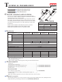
[4]-2. Engine and Shaft
Fig. 1
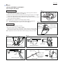
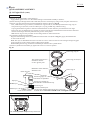
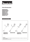
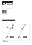
DISASSEMBLING
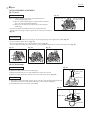
(1) Disconnect lead wire and grounding wire by removing each connector
after removal of Air cleaner cover. (Fig. 1)
(2) Remove Control cable from Insulator by loosening the adjust screw (Fig. 2)
then by the disconnecting inner cable from Swivel of Carburetor.
(3) Loosen two M5x18 Hex socket head bolts on Pipe holder and remove M5x12
Hex socket head bolt. (Fig. 3)
(4) Pull Shaft pipe complete out of Engine (Pipe holder).
Note:: Shaft in the Shaft pipe may get stuck at the spline engagement.
Fig. 2
Use Waterpump pliers to pull out the shaft. (Fig. 4)
Connector (4pcs.)
Inner cable
of Control
cable
Take the disassembling step in reverse.
Projection
• Set Control cable in place. (Figs. 2 and 6)
- Secure it on the projection of Insulator with two Nuts of Control cable. of Insulator
- Fit the hook of Inner cable end into the groove of Swivel of Carburetor.
Note: Adjust the tension of the cable to allow the play 1mm up to 2mm.
Swivel
Adjust screw of
Control cable
ASSEMBLING
Fig. 3
Nuts of Control
cable
Fig. 4
M5x13 Hex.
socket head bolt
Shaft pipe Shaft
M5x18 Hex.
socket head bolt (2pcs.)
Shaft pipe complete
Pipe holder
Fig. 5
Pipe holder
Fig. 6
Hook to fit into Swivel
Insulator
Adjust screw
Inner cable
Shaft
Water pump pliers
Control cable
Nuts to fix on
the projection
of Insulator
P 4/ 14
Repair
[4] DISASSEMBLY/ASSEMBLY
[4]-3. Shaft pipe complete
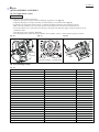
DISASSEMBLING
(1) Loosen two M6x30 Hex. socket head bolt (2pcs.) and remove Protector with Protector extension attached. (Fig. 7)
(2) Enlarge the space between the side wall of Protector cover and M5x14 Hex socket head bolt, and remove Protector cover
from Shaft pipe complete. (Fig. 8)
(3) Remove M5x14 Hex socket head bolt with Flat washer and spring washer then remove Protector clamp.
(4) Loosen M5x25 Hex socket head bolt then remove Gear case assembly. (Fig. 9)
(5) Remove four M5x30 Pan head screws then remove Loop handle and Handle clamp 24 from Shaft pipe complete. (Fig. 10)
(6) Remove four 4x18 Tapping screws and two M5x14 Hex socket head bolts then separate Lever case R and L. (Fig. 11)
(7) According to the clause of [4]-2, Remove Shaft pipe complete.
(8) Remove Hanger and Shaft from Shaft pipe complete. (Fig. 12)
Fig. 8
Fig. 7
M6x30 Hex. socket
head bolt (2pcs.)
M5x14 Hex socket head bolt
with Flat washer and
Spring washer
Shaft pipe
complete
Protector
Gear case
assembly
The side wall of
Protector cover
Protector extension
Fig. 9
Fig. 10
Gear case assembly
M5x30 Pan head
screw (4pcs.)
Shaft pipe
complete
M5x14 Hex socket
head bolt with Flat washer
and spring washer (2 pcs.)
M5x25 Hex
socket head bolt
Protector clamp
Fig. 11
Loop
handle
Handle
clamp 24
Fig. 12
Note: Hanger has to be assembled to Shaft pipe complete
in direction of the following arrow.
Lever case set
Hanger
M5x14 Hex socket
head bolt
4x18 Tapping screw
The distance between a hole
and one pipe end is long.
Shaft
ASSEMBLING
Assemble in the reverse order of disassembly.
• Slip Hanger on Shaft pipe complete as drawn in Fig. 12.
The distance is short.
Shaft pipe complete
P 5/ 14
Repair
[4] DISASSEMBLY/ASSEMBLY
[4]-4. Gear case assembly
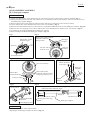
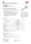
DISASSEMBLING
(1) According to the clause of [4]-3, Remove Gear case assembly.
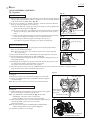
(2) Remove M8x10 + Hex bolt that is the stopper of Grease inlet on Gear case set. (Fig. 13)
(3) Remove Retaining ring R-24 with 1R006. (Fig. 14)
(4) Remove an assembled part of Spiral bevel gear 14, Ball bearing 609ZZ and Retaining ring S-9 by striking Gear case
assembly against workbench as drawn in Fig. 15.
(5) Remove Retaining ring S-9 with 1R291.
(6) Receive Ball bearing 609ZZ with 1R031, then press down the top of Spiral bevel gear 14 using 1R282 with Arbor press
(Fig. 16) Refer to Fig. 17 for the components.
(7) Remove Retaining ring R-28 with 1R291. (Fig. 18)
(8) Pretighten Receive washer and 1R033 with M10-17 Hex. nut to Cutter shaft as drawn in Fig. 19, and give
the impacts using the plastic hammer. An assembled part of Cutter shaft complete, Ball bearing 6001LLU is removed.
Refer to Fig. 20 for the components.
(9) Remove Ball bearing 6001LLU with 1R045.
Fig. 15
Fig. 13
Fig. 16
M8x10 + Hex bolt
1R282
Ball bearing 609ZZ
Fig. 14
1R031
Retaining ring R-24
Workbench
Fig. 17
Fig. 18
Spiral bevel gear 14
(The component of Cutter shaft set)
M8x10 + Hex bolt
Ball bearing 609ZZ
Retaining ring
S-28
Retaining ring S-9
Retaining ring R-24
Fig. 19
Receive
washer
Gear case
Fig. 20
1R033
M10-17 Hex. nut
Cutter shaft set
(Note: Spiral bevel bear 14 shown in Fig. 17 is also
the component.)
Ball bearing 6001LLU
Retaining ring R-28
ASSEMBLING
Take the disassembling step in reverse.
• Receive Gear case assembly with the U-shape table of Arbor press,
then press down Ball bearing 6001LLU using 1R028 with Arbor
press to insert Cutter shaft set in place.
Fig. 21
Ball bearing 6001LLU
1R028
P 6/ 14
Repair
[4] DISASSEMBLY/ASSEMBLY
[4]-5. Clutch
Fig. 22
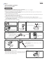
DISASSEMBLING
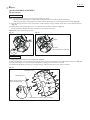
Note: (1) Clutch can be easily removed with Impact driver
without holding the piston.
(2) Do not remove Spark plug as compressed air resistance
has to be used for the disassembling.
(3) Plug cap with Plug cap spring has to be removed from
Spark plug.
• Loosen two M6x25 shoulder hex bolts by turning each bolt
counterclockwise using Cordless impact driver with 13mm Socket bit.
(Fig. 22)
13mm Socket bit
M6x25 shoulder
hex bolt (2pcs.)
ASSEMBLING
• Because M6x25 shoulder hex bolt (2pcs.) has the stepped shape. First tighten it by hand (Fig. 23),
next use cordless impact driver. (Fig. 24)
Note: Face the marking of L to the outside as drawn in Fig. 25.
Turn two M6x25 shoulder hex bolts clockwise using Cordless impact driver with 13mm Socket bit. (Fig. 25)
Fig. 23
Fig. 24
Fig. 25
L
[4]-6. Clutch drum
DISASSEMBLING
Fig. 26
(1) Remove Clutch case section from the engine.
(2) Remove Retaining ring S-12 with 1R004 from clutch case section.
(3) Remove Clutch drum from Clutch case section with Arbor press. (Fig. 26)
Arbor press
1R247
ASSEMBLING
Clutch case
(1) Put Clutch case on the table of Arbor press vertically, then pressfit Clutch drum into
Ball bearing 6201LLU with 1R286 and Arbor press as drawn in Fig. 27..
(2) Set Retaining ring S-12 in place with 1R004.
Fig. 27
Clutch drum
1R286
Clutch case
P 7/ 14
Repair
[4] DISASSEMBLY/ASSEMBLY
[4]-7. Ignition
Fig. 28
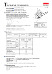
CHECK OF PLUG CAP
Plug cap
(1) Remove Plug cap from Spark plug, then detect the continuity between Plug cap
spring in Plug cap and Earth terminal of Ignition coil. It is the normal condition
when Tester shows 2.0kΩ±0.5kΩ. (Fig. 28)
(2) In case of no continuity or unstable continuity, check the connection between
Plug cap spring and Ignition coil as follows:
(A) Spray the lubricant in Plug cap, then pull out Plug cap spring together with
Ignition cable using Pliers. (Fig. 29)
(B) In case no connection or inconsistent connection, then check the condition
of Plug cap and spring. Reassemble them or replace them if they are disIgnition coil
order.
(C) Insert the end of Plug cap spring into Ignition cable then return them back
Fig. 29
to the inside of Plug cap carefully so as not to be disconnected.
(D) Check Plug cap and spring again according to the step of (1)
to avoid poor connection causing the poor sparks of Spark plug.
Earth terminal
Flywheel
Plug cap
Plug cap spring
CHECK OF SPARK PLUG
(1) Remove Plug cap with Plug cap spring, then remove Spark plug with Box
driver 16-17 (standard equipment).
Fig. 30
Note: When the spark area is wet with Fuel, wipe it away with a cloth and
dry it by air blow.
0.6 up to 0.7mm
(2) Clean carbonized materials on Insulated part for sparking with a wire brush.
(3) Do fine adjustment of Spark plug as drawn in Fig. 30.
Insert 0.7mm thickness gauge of 1R366 to the clearance and adjust the leg of
Leg
Spark plug carefully.
(4) Install Plug cap with Plug cap spring on Plug and connect the plug screw part
to a metal part of Engine, then pull Starter rope slowly.
The sparks can be seen when starter rope is pulled.
(5) When the sparks can not be seen, try [CHECK OF PLUG CAP] to detect the continuity. If required, replace
Plug and recheck the sparks through the above process.
DISASSEMBLING OF IGNITION COIL
See Fig. 31.
(1) Remove Cylinder cover and cable from Ignition coil terminal.
(2) Loosen two M4x20 Hex socket head bolts and remove Ignition
coil from Engine.
Note: Do not lose two spacers on the bolts as the heat protection.
Fig. 31
Spacer (2pcs.)
M4x20 Hex socket
head bolt (2pcs.)
ASSEMBLING OF IGNITION COIL
See Fig. 32.
(1) While attaching 0.3mm thickness gauge of 1R366 to the magnet
portion of Flywheel, set Ignition coil in place.
Note: Two M4x20 Hex socket head bolts (Fig. 31) are with
threadlocker. Therefore, when re-using them,
apply ThreeBond 1342 or Loctite 242 to the threads.
(2) After setting Ignition coil, remove the thickness gauge then turn
Flywheel by hand to check if it turns smoothly
without being stuck.
Note: Be sure to insert Spacer on M4x20 Hex socket head bolt
when fastening Ignition coil to Engine. (Fig. 31)
(3) Assemble Cylinder cover to Engine.
Tab of Ignition
coil to connect
with Cable
Connector of Cable
Fig. 32
Clearance between Flywheel
and Ignition coil: 0.3mm
P 8/ 14
Repair
[4] DISASSEMBLY/ASSEMBLY
[4]-8. Flywheel
DISASSEMBLING
Note: • Flywheel can be easily removed without holding the piston.
• Do not remove Spark plug as compressed air resistance has to be used for the disassembling.
• Plug cap with Plug cap spring has to be removed from Spark plug to prevent Engine from running. (Fig. 29)
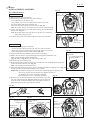
(1) Turn M8 Flange nut in the center of Flywheel counterclockwise using Cordless impact driver with 13mm Socket bit.
(Fig. 33)
(2) Install 1R364 on Flywheel then screw two M6 bolts into Flywheel as drawn in Fig. 34
instead of M6x25 shoulder hex bolts. Flywheel is removed from Engine.
Important: Screw two M6 bolts evenly
Fig. 34
Fig. 33
1R364
M8 bolts
(the components of 1R364)
Flange nut
(M8)
ASSEMBLING
(1) Wipe off the grease and oil from Crank shaft. (Fig. 35)
(2) Put Woodruff key 3 into Crank shaft, then align the key groove of Flywheel to the crank shaft with the key. (Fig. 35)
(3) Screw M8 Flange nut to the thread of Crank shaft by turning the nut clockwise by hand.
(4) Tighten the M8 flange nut about two seconds using Cordless impact driver with 13mm socket bit.
Fig. 35
Key groove of
Flywheel’s hole
Woodruff key 3
Wipe off the grease and
oil from Crank shaft.
Crankshaft (in cylinder block assembly)
P 9/ 14
Repair
[4] DISASSEMBLY/ASSEMBLY
[4]-9. Recoil starter
DISASSEMBLING
(1) Remove Starter case from Engine.
(2) Pull out and cut the rope when it is still connected.
If it is impossible to cut Starter rope;
First, pull the rope one turn of Reel, then, Hook the rope with
the notch of Reel and turn the hooked rope
clockwise until Spiral spring loses the tension. (Fig. 36)
Note: Be careful. Reel is revolved by the recoil force of Spiral spring.
(3) Loosen M5x12 Tapping screw and remove Swing arm and Reel from
Starter case. (Fig. 37)
Note: Be careful when removing this screw as there is a possibility
that Spiral spring pops out.
(4) Untie the knot of the rope in Reel and remove the rope from Reel.
Fig. 36
M5x12 Tapping
screw
(Set screw)
Fig. 37
Reel
notch of Reel
Swing arm
M5x12
Tapping screw
(Set screw)
ASSEMBLING
(1) When Spiral spring pops out of Reel:
- Set the one end of Spiral spring in the slot outer side in the Reel.
Fig. 38
- Rewind the spring counterclockwise toward the center of circle and
fit the spring end in the slot inside of Reel. (Fig. 38)
Curved end of Spiral spring
(2) Apply a little amount of Makita grease N No.2 to the spring.
(Outer side)
(3) Make a knot on the new rope end and pass it through Reel and Starter case,
Curved end of Spiral
then, connect the other end to Starter knob.
spring (Inside)
(Fig. 39) Refer to Fig. 40 how to make a knot of the rope.
(4) Wind the rope two or three turns.
(5) While turning Reel counterclockwise, fit it into Starter case and hook Spiral spring end
on the rib inside of Starter case. (Fig. 41)
Note: This should be fixed without force.
(6) Set Collar and Swing arm in place, then secure them with M5x12 Tapping screw. (Fig. 42)
Reel
Swing arm has to be passed through the groove of Reel.
Important: In case Reel turning is not smooth after tightening M5x12 Tapping screw,
Reel is not properly fixed to Starter case. Repeat the step (5)
so that Reel can revolves smoothly even after
Fig. 39
M5x12 Tapping screw is completely tightened.
(7) Hook the rope in the notch of Reel while straining the rope, then,
turn reel counterclockwise. (Fig. 43) When the rope is removed
from the notch, the Reel winds the rope with spring recoil force.
Repeat the step until the rope slacks are cleared.
Fig. 40
Approx. 10mm
Approx. 10mm
Fig. 41
Fig. 43
Fig. 42
Inside curved end
of Spiral spring
Inside rib of
Starter case
Groove of Reel
to hook
Swing arm
Swing arm
notch of Reel
Collar
M5x12
Tapping screw
(Set screw)
Swing arm
P 10/ 14
Repair
[4] DISASSEMBLY/ASSEMBLY
[4]-10. Carburetor
DISASSEMBLING
(1) Remove Cleaner cover assembly. (Fig. 44)
(2) Remove Air cleaner element. (Fig. 45)
(3) Remove two M5x60 Hex. socket head bolts for fastening
Carburetor and Cleaner plate assembly to Insulator.
Note: Carburetor can not removed before the bolts are removed
completely.
(4) Disconnect two tubes from Carburetor, then remove it.
Fig. 45
Fig. 44
Air cleaner
element
M5x60 Hex. socket button
head bolts are completely
removed.
CLEANING / MAINTENANCE
Refer to Fig. 46.
(1) Remove four 3x24 Tapping screws, then separate Metering diaphragm and Metering diaphragm gasket.
Note: In case Metering diaphragm remains attached to the others in disassembling of Carburetor, be careful to remove
Metering diaphragm and gasket. It is fragile.
(2) Replace Metering diaphragm when the following problems happen:
• slackened • hardened • worn / debased
(3) Loosen M3x4 screw in Pump body to remove Inlet needle and Control lever etc. (Refer to Fig. 47) from Carburetor.
(4) Before assembling Pump body, check that the top of Inlet needle is not deformed / worn out. (Fig. 48).
(5) When Control lever is set in place, make sure that Spring is put properly as drawn in Fig. 49.
(6) Regarding three M3x8 Pan head screws with washers, loosen Idling screw fully first, and then remove them.
(7) After checking if Inlet screen is clogged with dust, fit it into Pump body.
(8) Spray carburetor cleaner each route in Carburetor and then clean it with gasoline after a few minutes.
Fig. 47
Fig. 46
Carburetor
M3x8 Pan head screw
with washer
Swivel
(2pcs.)
Inlet
Washer
screen
Pump body
(M3x4 + screw
is included.)
(Throttle valve
assembly)
Spring
Inlet needle
M3x4 + screw
Stop ring
E-3
Metering
diaphragm
gasket
Pin
Idling screw
Note:
These items can
not be supplied
solely.
Order Pump body
to replace them.
Fig. 49
Metering
diaphragm
Conical
compression
spring 5-9
Air purge body
Primer pump
O ring 2
Primer pump
cover
3x24 Tapping
screw (4pcs.)
Fig. 48
Out of order
Normal
Jet
Pump gasket
Normal
Control lever
Out of order
Pump
diaphragm
Dust in Pump
body causes
the leakage of
pressure.
P 11/ 14
Repair
[4] DISASSEMBLY/ASSEMBLY
[4]-10. Carburetor (cont.)
ASSEMBLING
Carefully assemble each part in right direction and order.
Fig. 50
TEST OF AIRTIGHT STRUCTURE
(Nipple to connect
yellow tube of Tank)
1R127
Connect 1R127 to the nipple of Carburetor as drawn in Fig. 50.
Give air pressure from 1R127 and check if the pressure gauge indicates
0.05Mpa for around 10 seconds, then, there is no problem with
Carburetor.
ASSEMBLING TO ENGINE
Nipple of Carburetor to connect
black tube of Tank
(1) Assemble Cleaner plate assembly, Carburetor and Gasket to Insulator
Fig. 51
with two M5x60 Hex socket head bolts.
(2) Connect black tube of Fuel tank to the nipple of Carburetor.
Connect yellow tube of Fuel tank to the other nipple of Carburetor.
(Figs. 50 and 51)
Connect Tube from Cylinder and Breather pipe to the
Fuel tank
Cleaner plate assembly.
Note: Make sure that fuel tubes do not touch on Cylinder cover.
(3) Set Air cleaner elements in place. The felt element is put on the bottom,
and the sponge element is on the front.
(4) Hook the tabs of Cleaner plate assembly with the holes of Cleaner cover
assembly. (Fig. 52)
Fig. 52
Black tube
Yellow tube
Tabs of Cleaner plate assembly
[4]-11. Stop switch
Fig. 53
Check the continuity of two Lead wires’ ends
routed from Control lever with Tester. (Fig. 53)
[4]-12. Fuel tube
Fig. 54
Assemble Tube complete (Black tube, Yellow tube and
Grommet) to Fuel tank as drawn in Fig. 54.
Black tube
Assemble Gasoline filter and Hose clamp to the black tube,
then put them into Fuel tank. (Fig. 55)
Fig. 55
Yellow tube
Black tube
Grommet
Gasoline filter Hose clamp
P 12/ 14
Repair
[4] DISASSEMBLY/ASSEMBLY
[4]-13. Spark arrester (Only for some countries, i.e., having dry atmospheres at high temperature)
MAINTENANCE
(1) Remove Cylinder cover.
(2) Remove Exhaust Muffler.
(3) Remove Spark arrester from Exhaust muffler(Fig. 56).
Sweep it off if dirt or soot is on Spark arrester.
Replace it wit a new one if spark arrester has a breakage or fray.
(4) Assemble Spark arrester to Exhaust muffler.
(5) Set Exhaust muffler in place.
Note: • Refer to Parts breakdown, and do not forget muffler gasket.
• Two M5x40 Hex socket head bolts on Exhaust muffler are
threadlocker type. Once removing them for repair, apply
ThreeBond 1342 / Loctite 242 to the threads to screw them.
(6) Set Cylinder cover in place.
Fig. 56
Spark arrester
Exhaust muffler
[4]-14. Engine block
DISASSEMBLING
Fig. 57
(1) Drain the oil from Engine as much as possible so that the remaining oil
is not spilled out when disassembling.
(2) Remove the following parts from Engine.
• Cylinder cover • Tank guard • Fuel tank • Clutch case
• Recoil starter assembly • Clutch • Ignition coil • Flywheel
• Rocker cover inner • Rocker cover gasket • Rocker arm assembly
• Rod 2.5 • Cam lifter • Cam gear • Insulator • Air cleaner • Carburetor
• Spark plug • Muffler
(3) Open Cylinder block by removing six M5x16 Hex socket head bolts. (Fig. 57)
(4) Remove Clip from Piston with needle. (Fig. 58)
Fig. 58
Note: • Be careful as the clip pops out.
• Use the new clip. Do not use the used clip.
(5) Push Piston pin out with 1R171. (Fig. 59)
(6) Remove Piston.
Clip
Cylinder block
Fig. 59
1R171
P 13/ 14
Repair
[4] DISASSEMBLY/ASSEMBLY
[4]-14. Engine block (cont.)
ASSEMBLING
(1) Piston can be assembled in either direction.
Apply Makita grease N No. 2 to the needle bearing of Crank shaft assembly in advance.
(2) Insert Piston pin through Piston and Crank shaft, and fix it with Clips by using an awl (Clip has no direction).
(3) Piston rings have their directions and each different shapes as drawn in Fig. 60.
First, install Piston ring 34, and next, install Piston ring (second) 34, then finally install Piston ring (top) 34.
The piston ring 34 (fast one) consists of three part ; top ring, middle ring and bottom ring.
Top ring and bottom ring have a clearance and the distance of each clearance point must have 120° angle.
Piston ring (top) 34 and Piston ring (second) 34 consist of single part and the distance between their clearances
must have 180° angle when they fixed into the grooves on the piston.
Note: Piston rings are easy to break. Do not enlarge them too much when fixed.
(4) Assemble Cylinder block assembly.
Degrease the matching surface of Cylinder block and Crank case (Refer to Fig. 61), apply ThreeBond 1216
on the Crank case side.
Note: The layer of ThreeBond 1216 has to be thin so as not to enter into the oil route in Engine and get clogged.
Apply 4stroke oil to the contact surface of Piston and Cylinder.
While holding Piston rings, Install the assembled part of Piston into Cylinder block.
(5) Fasten Cylinder block assembly by tighten the screws in crisscross pattern.
Fig. 60
Piston ring (top) 34
The position between two
clearances must be
at 180° opposite point.
Piston top end
Difference of the clearance
should be 120°.
Piston ring (second) 34
Piston ring 34
Piston ring (top) 34
The center is expanded.
Top layer
Piston ring (second) 34
The bottom is wider than the top.
Middle layer
Bottom layer
Cross section of Piston
Piston ring 34
consists of three layers.
The top layer and the bottom layer have a clearance
as drawn above. Clearances should not be overlapped each other.
Fig. 61
The matching surface: emphasized by black color
Piston
P 14/ 14
Repair
[4] DISASSEMBLY/ASSEMBLY
[4]-14. Engine block (cont.)
ASSEMBLING
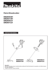
(6) Adjust the valve clearance as follows:
• Align the marking on Flywheel with the marking on Ignition coil. (Fig. 62)
• Align the marking on Cam gear assembly with the marking on Cylinder block. (Fig. 63)
• Assemble two Cam lifters and two Rod 2.5, and then assemble two Rocker arm assembly to them.
Note: The ends of Rod 2.5 have to be put into the round depressions of Cum lifter and Rocker arm.
• Loosen the adjust screws of Rocker arm assembly, and put 0.1mm thickness gauge of 1R366 between valves
and Rocker arms.
Then adjust the valve clearance. (Fig. 64)
• After the adjustment, tighten the nuts of Rocker arm assembly, remove 0.1mm thickness gauge of 1R366.
Fig. 63
Fig. 64
Fig. 62
Marking on Ignition coil
1R170
Marking
on
Flywheel
Marking on
Marking on
Cam gear assembly Cylinder block
1R366
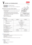
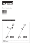
[4]-15. Fastening torque
Fig. 65
Parts to fasten
Screw/ Nut
Fastening torque (N・m)
CYLINDER BLOCK and CRANK CASE
HEX SOCKET HEAD BOLT(M5×16)
6.0
CRANK CASE and RETAINER PLATE
HEX SOCKET HEAD BOLT (M4×10)
3.0
CRANK CASE and OIL CASE
HEX SOCKET HEAD BOLT(M5×16)
FLYWHEEL and CRANK SHAFT 1
FLANGE NUT (M8)
COIL and CYLINDER BLOCK
HEX SOCKET HEAD BOLT (M4×20,W,SW,MEC)
4.0
CAM GEAR COVER and CYLINDER BLOCK
HEX SOCKET HEAD BOLT(M5×16)
6.0
ROCKER ARM ADJUSTING SCREW and NUT
NUT (M5)
6.0
ROCKER COVER OUTER and CYLINDER BLOCK HEX SOCKET HEAD BOLT(M5×16)
6.0
16.0
6.0
CLUTCH and FLYWHEEL
CLUTCH BOLT (M6×25)
9.0
MUFFLER and CYLINDER BLOCK
HEX SOCKET HEAD BOLT(M5×40,W,MEC)
8.0
SPARK PLUG and CYLINDER BLOCK
M10×P1.0
INSULATOR and CYLINDER BLOCK
HEX SOCKET HEAD BOLT (M5×18,W,SW)
5.0
CLUTCH CASE and CYLINDER, CRANK CASE
HEX SOCKET HEAD BOLT(M5×18,W,SW)
5.0
PULLEY and CRANK SHAFT 2
M8
6.0
11.0
RECOIL STARTER and CYLINDER, CRANK CASE HEX SOCKET HEAD BOLT (M5×16,W,SW)
5.0
MUFFLER PLATE and CRANK CASE
HEX SOCKET HEAD BOLT (M5×14,W,SW)
5.0
OIL PIPE and OIL CASE
HEX SOCKET HEAD BOLT (M5×14,W,SW)
5.0
CASE, GEAR ASSEMBLY and PIPE SHAFT
HEX SOCKET HEAD BOLT (M5×25,SW)
7.0
CASE, GEAR ASSEMBLY and PIPE SHAFT
HEX SOCKET HEAD BOLT (M5×14,SW)
7.0
HANDLE HOLDER 2, 3 and PIPE SHAFT
HEX SOCKET HEAD BOLT (M5×30,SW)
6.0
CONTROL LEVER and HANDLE
SCREW PAN HEAD (M5×20)
3.0
BRACKET PIPE and SHAFT PIPE COMPLETE
HEX SOCKET HEAD BOLT (M5×12,SW)
6.0
CONTROL CABLE and INSULATOR
NUT (M6)
2.0