1
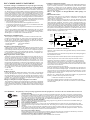
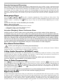
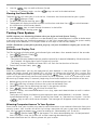
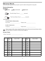
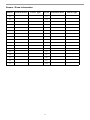
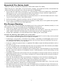
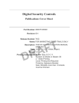
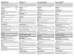
User Guide
Self Contained Wireless Alarm System v1.0
N11427
WARNING: This manual contains information on limitations regarding product use and
function and information on the limitations as to liability of the manufacturer.
The entire manual should be carefully read.
FCC COMPLIANCE STATEMENT
CAUTION: Changes or modifications not expressly approved by Digital Security Controls could void your authority to use this equipment.
This equipment has been tested and found to comply with the limits for a
Class B digital device, pursuant to Part 15 of the FCC Rules. These limits
are designed to provide reasonable protection against harmful interference in a residential installation. This equipment generates, uses and can
radiate radio frequency energy and, if not installed and used in accordance with the instructions, may cause harmful interference to radio communications. However, there is no guarantee that interference will not
occur in a particular installation. If this equipment does cause harmful interference to radio or television reception, which can be deter-mined by
turning the equipment off and on, the user is encouraged to try to correct
the interference by one or more of the following measures:
• Re-orient the receiving antenna.
• Increase the separation between the equipment and receiver.
• Connect the equipment into an outlet on a circuit different from that
to which the receiver is connected.
• Consult the dealer or an experienced radio/television technician for
help.
The user may find the following booklet prepared by the FCC useful:
“How to Identify and Resolve Radio/Television Interference Problems”.
This booklet is available from the U.S. Government Printing Office,
Washington D.C. 20402, Stock # 004-000-00345-4.
IMPORTANT INFORMATION
This equipment complies with Part 68 of the FCC Rules and, if the
product was approved July 23, 2001 or later, the requirements adopted
by the ACTA. On the side of this equipment is a label that contains,
among other information, a product identifier. If requested, this number
must be provided to the Telephone Company.
Product Identifier:
US:F53AL01B9047
USOC Jack:
RJ-31X
Telephone Connection Requirements
A plug and jack used to connect this equipment to the premises wiring
and telephone network must comply with the applicable FCC Part 68
rules and requirements adopted by the ACTA. A compliant telephone
cord and modular plug is provided with this product. It is designed to
be connected to a compatible modular jack that is also compliant. See
installation instructions for details.
Ringer Equivalence Number (REN)
The REN is used to determine the number of devices that may be connected to a telephone line. Excessive RENs on a telephone line may result in the devices not ringing in response to an incoming call. In most
but not all areas, the sum of RENs should not exceed five (5.0). To be
certain of the number of devices that may be connected to a line, as determined by the total RENs, contact the local Telephone Company. For
products approved after July 23, 2001, the REN for this product is part
of the product identifier that has the format US: AAAEQ##TXXXX.
The digits represented by ## are the REN without a decimal point (e.g.,
03 is a REN of 0.3). For earlier products, the REN is separately shown
on the label.
REN = 0.1B
Incidence of Harm
If this equipment (SCW9047/SCW9045) causes harm to the telephone
network, the telephone company will notify you in advance that temporary discontinuance of service may be required. But if advance notice is
not practical, the Telephone Company will notify the customer as soon as
possible. Also, you will be advised of your right to file a complaint with
the FCC if you believe it is necessary.
Changes in Telephone Company Equipment or Facilities
The Telephone Company may make changes in its facilities, equipment,
operations or procedures that could affect the operation of the equipment.
If this happens the Telephone Company will provide advance notice in
order for you to make necessary modifications to maintain uninterrupted
service.
Equipment Maintenance Facility
If trouble is experienced with this equipment (SCW9047/SCW9045) for
repair or warranty information, contact the facility indicated below. If the
equipment is causing harm to the telephone network, the Telephone
Company may request that you disconnect the equipment until the problem is solved. This equipment is of a type that is not intended to be repaired by the end user.
DSC c/o APL Logistics 757 Douglas Hill Rd., Lithia Springs, GA
30122
Additional Information
Connection to party line service is subject to state tariffs. Contact the state
public utility commission, public service commission or corporation
commission for information.
Alarm dialling equipment must be able to seize the telephone line and
place a call in an emergency situation. It must be able to do this even if
other equipment (telephone, answering system, computer modem, etc.)
already has the telephone line in use. To do so, alarm dialling equipment
must be connected to a properly installed RJ-31X jack that is electrically
in series with and ahead of all other equipment attached to the same telephone line. Proper installation is depicted in the figure below. If you have
any questions concerning these instructions, you should consult your telephone company or a qualified installer about installing the RJ-31X jack
and alarm dialling equipment for you.
Customer Premises Equipment and Wiring
Network
Service
Provider's
Facilities
Computer
RJ-31X
Jack
Alarm Dialing
Equipment
Unused
RJ-11 Jack
Telephone
Line
Telephone
Network
Demarcation
Point
Fax Machine
Telephone
Answering
System
Unused
RJ-11 Jack
Telephone
INDUSTRY CANADA STATEMENT
NOTICE: This product meets the applicable Industry Canada technical
specifications.
Le présent materiel est conforme aux specifications techniques applicables d’Industrie Canada.
The Ringer Equivalence Number (REN) for this terminal equipment is 0.1 .
L'indice d'équivalence de la sonnerie (IES) du présent matériel est de 0.1.
The Ringer Equivalence Number is an indication of the maximum
number of devices allowed to be connected to a telephone interface.
The termination on an interface may consist of any combination of devices subject only to the requirement that the sum of the RENs of all the
devices does not exceed five.
L’indice d’équivalence de la sonnerie
(IES) sert à indiquer le nombre maximal de terminaux qui peuvent être
raccordés à une interface téléphonique. La terminaison d’une interface
peut consister en une combinaison quelconque de dispositifs, à la seule
condition que la somme d’indices d’équivalence de la sonnerie de tous
les dispositifs n’excède pas 5.
The term “IC:” before the radio certification number only signifies that
Industry Canada technical specifications were met.
Certification Number IC: 160A-9047
This Class B digital apparatus complies with Canadian ICES-003.
Cet appareil numérique de la classe B est conforme à la norme NMB003 du Canada.
These DSC Security Alarm
Systems may be connected
Telecom Network
PTC 211 / 08 / 003
SCW9045-433
PTC 211 / 08 / 003
SCW9047-433
RN = 1
New Zealand - The following is a list of warnings applicable when this equipment is connected to the New Zealand Telecom Network.
General Warning
The grant of a Telepermit for any item of terminal equipment indicates only that Telecom has accepted that the
item complies with minimum conditions for connection to its network. It indicates no endorsement of the product
by Telecom, nor does it provide any sort of warranty. Above all, it provides no assurance that any item will work
correctly in all respects with another item of Telepermitted equipment of a different make or model, nor does it
imply that any product is compatible with all of Telecom's network services.
Reverse Numbering (decadic signalling)
Decadic signalling should not be used as it is being progressively phased out of the network. DTMF dialling is
100% available and it should always be used.
Line Grabbing Equipment
This equipment is set up to carry out test calls at pre-determined times. Such test calls will interrupt any other
calls that may be set up on the line at the same time. The timing set for such test calls should be discussed with the
installer.
The timing set for test calls from this equipment may be subject to 'drift'. If this proves to be inconvenient and
your calls are interrupted, then the problem of timing should be discussed with the equipment installer. The matter should NOT be reported as a fault to Telecom Faults Service.
D.C. Line Feed to Other Devices
During dialling, this device unit does not provide DC voltage to the series port connection and this may cause loss
of memory functions for the terminal devices (local telephone) connected to T-1, R-1.
General Operation (ringer sensitivity and loading)
This device only responds to Distinctive Alert cadences DA1 and DA2.
Table of Contents
About Your Security System . . . . . . . . . . . . . . . . . . . . . . . . . . . . . . . . . . . . . . . . . .
Fire Detection . . . . . . . . . . . . . . . . . . . . . . . . . . . . . . . . . . . . . . . . . . . . . . . . . . . .
Testing . . . . . . . . . . . . . . . . . . . . . . . . . . . . . . . . . . . . . . . . . . . . . . . . . . . . . . . . .
Monitoring . . . . . . . . . . . . . . . . . . . . . . . . . . . . . . . . . . . . . . . . . . . . . . . . . . . . . . .
Maintenance . . . . . . . . . . . . . . . . . . . . . . . . . . . . . . . . . . . . . . . . . . . . . . . . . . . . .
General System Operation . . . . . . . . . . . . . . . . . . . . . . . . . . . . . . . . . . . . . . . . . .
1
1
1
1
1
1
Controls & Indicators. . . . . . . . . . . . . . . . . . . . . . . . . . . . . . . . . . . . . . . . . . . . . . . . . 2
Language Selection . . . . . . . . . . . . . . . . . . . . . . . . . . . . . . . . . . . . . . . . . . . . . . . . . 2
Arming & Disarming the System . . . . . . . . . . . . . . . . . . . . . . . . . . . . . . . . . . . . . . .
Stay Arming . . . . . . . . . . . . . . . . . . . . . . . . . . . . . . . . . . . . . . . . . . . . . . . . . . . . .
Night Arming . . . . . . . . . . . . . . . . . . . . . . . . . . . . . . . . . . . . . . . . . . . . . . . . . . . . .
Silent Exit Delay . . . . . . . . . . . . . . . . . . . . . . . . . . . . . . . . . . . . . . . . . . . . . . . . . .
Away Arming . . . . . . . . . . . . . . . . . . . . . . . . . . . . . . . . . . . . . . . . . . . . . . . . . . . .
Quick Exit . . . . . . . . . . . . . . . . . . . . . . . . . . . . . . . . . . . . . . . . . . . . . . . . . . . . . . .
Bell/Siren Sounds After Away Arming . . . . . . . . . . . . . . . . . . . . . . . . . . . . . . . . .
Disarming . . . . . . . . . . . . . . . . . . . . . . . . . . . . . . . . . . . . . . . . . . . . . . . . . . . . . . .
Remote Arming and Disarming . . . . . . . . . . . . . . . . . . . . . . . . . . . . . . . . . . . . . .
2
2
3
3
3
3
3
3
4
Emergency Keys . . . . . . . . . . . . . . . . . . . . . . . . . . . . . . . . . . . . . . . . . . . . . . . . . . . .
When Alarm Sounds. . . . . . . . . . . . . . . . . . . . . . . . . . . . . . . . . . . . . . . . . . . . . . .
Intrusion (Burglar) Alarm Continuous Siren . . . . . . . . . . . . . . . . . . . . . . . . . . . . .
Fire Alarm Pulsed Siren . . . . . . . . . . . . . . . . . . . . . . . . . . . . . . . . . . . . . . . . . . . .
4
4
4
4
2-Way Audio Audio Operation (SCW9047 only) . . . . . . . . . . . . . . . . . . . . . . . . . . . 4
Time & Date Programming . . . . . . . . . . . . . . . . . . . . . . . . . . . . . . . . . . . . . . . . . . . . 4
Bypassing Zones . . . . . . . . . . . . . . . . . . . . . . . . . . . . . . . . . . . . . . . . . . . . . . . . . . . 4
Trouble Conditions . . . . . . . . . . . . . . . . . . . . . . . . . . . . . . . . . . . . . . . . . . . . . . . . . . 6
Alarm Memory . . . . . . . . . . . . . . . . . . . . . . . . . . . . . . . . . . . . . . . . . . . . . . . . . . . . . . 6
Door Chime (Entry/Exit Beeps) . . . . . . . . . . . . . . . . . . . . . . . . . . . . . . . . . . . . . . . . 6
Access Code Programming . . . . . . . . . . . . . . . . . . . . . . . . . . . . . . . . . . . . . . . . . . .
Access Codes . . . . . . . . . . . . . . . . . . . . . . . . . . . . . . . . . . . . . . . . . . . . . . . . . . .
User Code Attributes . . . . . . . . . . . . . . . . . . . . . . . . . . . . . . . . . . . . . . . . . . . . . .
Zone Bypassing Attribute . . . . . . . . . . . . . . . . . . . . . . . . . . . . . . . . . . . . . . . . . . .
Bell Squawk Attribute . . . . . . . . . . . . . . . . . . . . . . . . . . . . . . . . . . . . . . . . . . . . .
Erasing an Access Code . . . . . . . . . . . . . . . . . . . . . . . . . . . . . . . . . . . . . . . . . . .
7
7
7
7
8
8
User Function Commands . . . . . . . . . . . . . . . . . . . . . . . . . . . . . . . . . . . . . . . . . . . .
Changing Brightness/Contrast . . . . . . . . . . . . . . . . . . . . . . . . . . . . . . . . . . . . . . .
Changing the Buzzer Level . . . . . . . . . . . . . . . . . . . . . . . . . . . . . . . . . . . . . . . . .
Viewing the Event Buffer . . . . . . . . . . . . . . . . . . . . . . . . . . . . . . . . . . . . . . . . . . .
8
8
8
9
Testing Your System . . . . . . . . . . . . . . . . . . . . . . . . . . . . . . . . . . . . . . . . . . . . . . . .
Sounder and Display Test . . . . . . . . . . . . . . . . . . . . . . . . . . . . . . . . . . . . . . . . . .
Walk Test . . . . . . . . . . . . . . . . . . . . . . . . . . . . . . . . . . . . . . . . . . . . . . . . . . . . . . .
Allowing Computer Access To Your System . . . . . . . . . . . . . . . . . . . . . . . . . . . .
9
9
9
9
i
Reference Sheets . . . . . . . . . . . . . . . . . . . . . . . . . . . . . . . . . . . . . . . . . . . . . . . . . . .
System Information. . . . . . . . . . . . . . . . . . . . . . . . . . . . . . . . . . . . . . . . . . . . . . .
Access Codes. . . . . . . . . . . . . . . . . . . . . . . . . . . . . . . . . . . . . . . . . . . . . . . . . . .
Sensor / Zone Information . . . . . . . . . . . . . . . . . . . . . . . . . . . . . . . . . . . . . . . . .
10
10
10
11
Guidelines for Locating Smoke Detectors . . . . . . . . . . . . . . . . . . . . . . . . . . . . . . 12
Household Fire Safety Audit . . . . . . . . . . . . . . . . . . . . . . . . . . . . . . . . . . . . . . . . . 13
Fire Escape Planning . . . . . . . . . . . . . . . . . . . . . . . . . . . . . . . . . . . . . . . . . . . . . . . 13
Always ensure you obtain the latest version of the User Guide. Updated versions of this User
Guide are available by contacting your distributor.
IMPORTANT SAFETY INSTRUCTIONS
To reduce the risk of fire, electric shock and/or injury, observe the following safety precautions:
• Do NOT spill any type of Liquid On the equipment.
• Do NOT attempt to service this product yourself. Opening or removing the cover may expose you to
DANGEROUS VOLTAGES or other risk. Refer SERVICING TO Qualified Service Personnel. NEVER
Open the device yourself.
• Do NOT touch THE EQUIPMENT AND ITS CONNECTED CABLES DURING AN ELECTRICAL
STORM; THERE MAY BE A REMOTE RISK OF ELECTRIC SHOCK FROM LIGHTNING
• Do NOT use the Alarm System to report a gas leak if it is near the leak.
REGULAR MAINTENANCE AND TROUBLESHOOTING
Keep your Alarm Controller in optimum condition by following all the instructions that are included within
this Manual and/or marked on the product.
CLEANING
• Clean the enclosure (case) by wiping with a damp cloth only.
• DO NOT use abrasives, thinners, solvents or aerosol cleaners (spray polish) that may enter through
holes in the enclosure (case) of the Alarm Controller and cause damage.
• DO NOT use any water or any other liquid.
• Do not wipe the front cover with alcohol.
TROUBLESHOOTING
Occasionally, you may have a problem with your Alarm Controller or telephone line. If this happens, your
Alarm Controller usually identifies the problem and displays an error message. Refer to the provided list
when you see an error message on the display. If additional help is required, contact your distributor for
service.
WARNING
This equipment, SCW Alarm System SCW9045/47 shall be installed and used within an environment that
provides the pollution degree max 2 and over-voltages category II NON-HAZARDOUS LOCATIONS,
indoor only. The equipment is DIRECT PLUG-IN connected and is designed to be installed, serviced and/
or repaired by service persons only; [service person is defined as a person having the appropriate
technical training and experience necessary to be aware of hazards to which that person may be exposed
in performing a task and of measures to minimize the risks to that person or other persons].
There are no parts replaceable by the end-user within this equipment.
This publications covers the following models:
•SCW9047-433
•SCW9045-433
ii
About Your Security System
Your Security System has been designed to provide you with the greatest possible flexibility and convenience. Read this manual carefully and have your installer instruct you on your system's operation
and on which features have been implemented in your system. All users of this system should be
equally instructed in its use. Fill out the “System Information” page with all of your zone information
and access codes and store this manual in a safe place for future reference.
NOTE: Please consult your installer for further information regarding the false alarm reduction
features built into your system as all are not covered in this manual.
Fire Detection
This equipment is capable of monitoring fire detection devices such as smoke detectors and providing a warning if a fire condition is detected. Good fire detection depends on having adequate number of detectors placed in appropriate locations. This equipment should be installed in accordance
with NFPA 72 (N.F.P.A., Battery march Park, Quince MA 02269). Carefully review the Family Escape
Planning guidelines in this manual.
NOTE: Your installer must enable the fire detection portion of this equipment before it becomes
functional.
Testing
To ensure that your system continues to function as intended, you must test your system weekly.
Please refer to the “Testing your System” section in this manual. If your system does not function
properly, call your installing company for service.
Monitoring
This system is capable of transmitting alarms, troubles & emergency information to a central station. If you
initiate an alarm by mistake, immediately call the central station to prevent an unnecessary response.
NOTE: The monitoring function must be enabled by the installer before it becomes functional.
NOTE: This system has a communicator delay of 30 seconds. It can be removed, or it can be
increased up to 45 seconds by the installer.
NOTE: Ensure that your Installer verifies that your system is compatible with the Central Station
Receiver format at yearly intervals.
Maintenance
With normal use, the system requires minimum maintenance. Note the following points:
• Do not wash the security equipment with a wet cloth. Light dusting with a slightly moistened cloth
should remove normal accumulations of dust.
• DSC recommends replacing the standby batteries every 4-5 years.
• For other system devices such as smoke detectors, motion detectors, glassbreak detectors or door/
window contacts, consult the manufacturer’s literature for testing and maintenance instructions if
applicable.
General System Operation
Your security system comprises an integrated alarm control/keypad and various sensors and detectors. The system is mounted by the main exit/entry location. The system is self-contained; electronics
and standby battery are housed within the keypad unit.
NOTE: Only the installer or service professional should have access to the system.
The security system has several zones of area protection. Each of these zones communicates to a single wireless sensor (motion detectors, glassbreak detectors, door contacts, etc.) or to one or more
hard wired sensors. A sensor in alarm is indicated by messages on the LCD keypad.
Additional features include: Automatic Inhibit (Swinger Shutdown) for Alarm; Tamper and Trouble
signals after 3 occurrences in a given set period; and a Programmable Keypad Lockout option.
NOTE: For SIA CP-01 classified installations, the swinger shutdown feature is programmed such
that one or two trips will shut down the zone. The zone will be restored after a manual reset (by
entering the access code at the time of disarming the alarm system) or it will be reset automatically
after 48 hrs with no trips on any zones.
1
Controls & Indicators
IMPORTANT NOTICE
A security system cannot prevent emergencies. It is only intended to alert you and – if included – your
central station of an emergency situation. Security systems are generally very reliable but they may
not work under all conditions and they are not a substitute for prudent security practices or life and
property insurance. Your security system should be installed and serviced by qualified security professionals who should instruct you on the level of protection that has been provided and on system
operations.
Language Selection
Your system can display messages in different languages.
1. Press and hold both
keys simultaneously.
2. Using the
keys, scroll through the available languages.
3. Press
to select your desired language.
Arming & Disarming the System
Stay Arming
Stay arming will bypass the interior protection (i.e. motion sensors) and arm the perimeter of the system (i.e. doors and windows). Close all sensors (i.e. stop motion and close doors). The Ready ( )
indicator should be on.
Press and hold the Stay key for 2 seconds and/or enter your Access Code and do not leave the premises. During the setting state (exit delay active), the Armed ( ) and Ready ( ) indicators will light.
When the exit delay is completed, the alarm system is armed/set and this is indicated on the keypad
as follows: the Ready ( ) indicator will turn off, the Armed ( ) indicator will remain on.
The Armed ( ) indicator and a bypass message will be displayed. The system will automatically
bypass certain interior sensors (i.e. motion sensors).
NOTE: For SIA FAR listed panels, the Stay Arming Exit Delay will be twice as long as the Away
Arming Exit Delay.
NOTE: If your system is installed in accordance with SIA CP-01 Standard for False Alarm
Reduction then the security system will arm in the Stay Armed mode if the exit delay time expires
and no exit has been made.
2
Night Arming
To fully arm the system when it has been armed in Stay Mode, press
at the keypad. All interior zones will now be armed except for devices programmed as Night Zones.
Night zones are only armed in Away mode, this permits limited movement within the premises when
the system is fully armed. Ensure that your installer has provided you with a list identifying zones programmed as night zones.
When the interior zones have been activated (i.e.,
) you must enter your access code to disarm the system to gain access to interior areas that have not been programmed as night zones.
Silent Exit Delay
If the system is armed using the Stay key or using the ’No Entry’ Arming method (
[access
code]), the audible progress annunciation (keypad buzzer) will be silenced and the exit time will be
doubled for that exit period only.
Away Arming
Close all sensors (i.e. stop motion and close doors). The Ready ( ) indicator should be on.
To arm, press and hold the Away Key for 2 seconds and/or enter your Access Code, or press
to Quick Arm. During the setting state (exit delay active) the Armed ( ) and Ready ( ) indicators will
turn on, and the keypad will sound one beep per second. You now have ____ seconds to leave the
premises (please check with your installer to have this time programmed). An audible annunciation,
whose pulsating rate is distinctly different, will sound during the last ten seconds of the exit delay to
warn person(s) that the exit delay is running out. To cancel the arming sequence, enter your access
code.
When the exit delay is completed, the alarm system is armed/set and this is indicated on the keypad
as follows: the Ready ( ) indicator will turn off, the Armed ( ) indicator will remain on and the keypad will stop sounding.
NOTE: If your system is installed in accordance with SIA CP-01 Standard for False Alarm
Reduction then the violation, restoral followed by a second violation of the entry/exit zone before
the end of the exit delay will restart the exit delay.
Quick Exit
If the system is armed and you need to exit, use the Quick Exit function to avoid disarming and
rearming the system. Press and hold the Quick Exit key for 2 seconds or press
. You now have
2 minutes to leave the premises through your exit door. When the door is closed again, the remaining exit time is cancelled.
Bell/Siren Sounds After Away Arming
Audible Exit Fault
In an attempt to reduce false alarms, the Audible Exit Fault is designed to notify you of an improper
exit when arming the system. In the event that you fail to securely close the Exit/Entry door during
the allotted exit delay period, the system will sound the alarm to indicate an improper exit.
Your installer will tell you if this feature has been enabled on your system. If this occurs:
1. Re-enter the premises.
2. Enter your [access code] to disarm the system. You must do this before the entry delay timer
expires.
3. Follow the Away arming procedure again, ensure that the entry/exit door(s) are secured.
Arming Error
An error tone will sound if the system is unable to arm. This will happen if the system is not ready to
arm (i.e. sensors are open), or if an incorrect user code has been entered. If this happens, ensure all
sensors are secure, press
and try again.
Disarming
Enter your access code to disarm anytime the system is armed (Armed ( ) indicator is on). The keypad will sound a continuous tone after the entry delay has been initiated by opening the entry/exit
door. Enter your code within _____ seconds to avoid an alarm condition (check with your installer to
have this time programmed).
Disarming Error
If your code is invalid, the system will not disarm and a 2-second error tone will sound. If this happens, press
and try again.
3
Remote Arming and Disarming
The system can be armed and/or disarmed (if programmed by the installer) using a remote control
device (wireless key). When arming the system by using the Arm button on the wireless key, the system
will acknowledge the command by sounding a single bell squawk and when disarming using the Disarm button on the wireless key the system will acknowledge the command by sounding two bell
squawks . Three squawks heard when disarming with the disarm button indicates that that an alarm
occurred while the system was armed. If you are unsure of the cause of the alarm, proceed with caution.
Emergency Keys
Press the
(F),
(A) or
(P) key for 2 seconds to generate a Fire, Auxiliary or Panic alarm. The
keypad sounder will beep indicating that the alarm input has been accepted and transmission to the
central station is underway. The
(P) key may or may not sound the bell depending on Installer
setup.
NOTE: The Fire keys can be disabled by the installer.
When Alarm Sounds
The system can generate 2 different alarm sounds:
• Continuous Siren = Intrusion (Burglary Alarm)
• Temporal / Pulsed Siren = Fire Alarm
Intrusion (Burglary) Alarm Continuous Siren
NOTE: If you are unsure of the source of the alarm, proceed with caution! If the alarm was
accidental, enter your Access Code to silence the alarm. If the alarm system is disarmed within the
programmed Abort Window (check with the installer if this option has been enabled on your system
and what is the transmitter delay time programmed), no alarm transmission to the Central Station
will occur. Starting at the end of the Abort Window there is a five minute Cancel window, during
which a user can cancel, by entering his access code, an alarm that has been previously transmitted.
A cancel signal will be transmitted to the Central Station and the alarm system will also annunciate
that the cancel signal was transmitted. Call your central station to avoid a dispatch.
Fire Alarm Pulsed Siren
Follow your emergency evacuation plan immediately!
If the fire alarm was accidental (i.e. burned toast, bathroom steam, etc.), enter your Access Code to
silence the alarm. Call your central station to avoid a dispatch.
2-Way Audio Operation (SCW9047 only)
If programmed by the installer, this feature allows the monitoring station to initiate a 2-way audio
session when an alarm has been received. This feature is used to verify the nature of the alarm or
determine the type of assistance required by the occupant.
NOTE: This feature can be initiated only by the monitoring station after an alarm has been
received. The user can not initiate a 2-way audio session.
Time & Date Programming
Press
plus your Master Access Code to enter User Functions. Use the
scroll keys to find
the menu option then press
to select it. Enter the time in 24-hr. format (HH:MM), followed by the
date (MM:DD:YY). Press
to exit programming. If you are viewing a ‘Loss of Clock’, trouble from
within the trouble menu (
), press
to directly enter Date and Time programming. See Trouble Conditions on page 6),
NOTE: Your installer may have programmed your system to display the time and date while the keypad is idle. Press the
key to clear the date and time display if desired.
Bypassing Zones
Use the zone bypassing feature when you need access to a protected area while the system is armed,
or when a zone is temporarily out of service, but you need to arm the system. Bypassed zones will
not be able to sound an alarm. Bypassing zones reduces the level of security. If you are bypassing a
zone because it is not working, call a service technician immediately so that the problem can be
resolved and your system returned to proper working order. Ensure that no zones are unintentionally
4
bypassed when arming your system. Zones cannot be bypassed once the system is armed. Bypassed
zones are automatically cancelled each time the system is disarmed and must be bypassed again, if
required, before the next arming.
Bypassing Zones
With the system disarmed.
1. Press
to enter the function menu. The keypad will display “Press
for < > Zone Bypass”.
2. Press
or
, then your [access code] (if required). The keypad will display “Scroll to < >
Bypass Zones”.
3. Enter the two-digit number of the zone(s) to be bypassed (01-34).
You can also use the
keys to find the zone to be bypassed, and then press
to select the
zone. The keypad will display “Zone Name”. “B” will appear on the display to show that the zone is
bypassed. If a zone is open (e.g., door with door contact is open), the keypad will display “Zone Name”
O”. If you bypass the open zone, a “B” will replace the “O”.
4. To unbypass a zone, enter the two-digit number of the zone(s) to be bypassed (01-34). You can
also use the
keys to find the zone, and then press
to select the zone. The “B” will
disappear from the display to show that the zone is no longer bypassed.
5. To exit bypassing mode and return to the Ready state, press
.
Activating All Bypassed Zones
To remove bypass (all zones):
1. Press
, then your [access code] (if necessary).
2. Press
.
3. To exit bypassing mode and return to the Ready state, press
.
Recalling Bypassed Zones
To recall the last set of bypassed zones:
1. Press
2. Press
, then your [access code] (if necessary).
.
3. To exit bypassing mode and return to the Ready state, press
.
Bypass Group
A Bypass Group is a selection of zones programmed into the system. If you bypass a group of zones
on a regular basis, you can program them into the Bypass Group, so that you do not have to bypass
each zone individually every time. Only one Bypass Group can be programmed.
NOTE: If a group has already been bypassed before programming a Bypass Group, you will be
unable to recall that group after programming the new group.
To program a Bypass Group:
1. Press
, then your [access code] (if necessary).
2. Enter the two-digit numbers (01-34) of the zones to be included in the Bypass Group or
use the
keys to find the zone to be included in the bypass group, then press
to select the zone.
3. To save the selected zone into the group, press
.
4. To exit bypassing mode and return to the Ready state, press
.
NOTE: If an access code is required to enter bypassing, only the Master Code and codes with
Supervisory enabled can set the Bypass Group.
5
To select a Bypass Group when arming the system:
1. Press
, then your [access code] (if necessary).
2. Press
. The next time the system is armed, the zones in this group will be bypassed.
3. To exit bypassing mode and return to the Ready state, press
.
NOTE: A Bypass Group is only recalled if the system is armed/disarmed after programming the bypass group.
NOTE: This feature is not to be used in UL Listed installations.
Trouble Conditions
When a trouble condition is detected, the Trouble ( ) indicator will turn on, and the keypad will
beep every 10 seconds. Press the
key to silence the beeps. Press
to view the trouble condition. The Trouble ( ) indicator will flash. Use the
keys to view troubles.
Trouble
Condition
Service Required
(Press [1] for more
information)
Comments
Action
Indicates Low Battery, System Trouble, System Tamper or
RF Jam detected.
Call for service
Loss of AC Power
If the building and/or neighbourhood has lost electrical Check AC
power, the system will continue to operate on battery for connection
several hours.
Call for service
Telephone Line
Fault
The system has detected that the telephone line is disconnected.
Call for service
Failure to
Communicate
The system attempted to communicate with the monitoring station, but failed. This may be due to Telephone
Line Fault.
Call for service
Sensor (or Zone)
Fault
The system is experiencing difficulties with one or more
sensors on the system. Press [5] to display zone(s).
Call for service
Sensor (or Zone)
Tamper
The system has detected a tamper condition with one or
Call for service
more sensors on the system. Press [6] to display zone(s).
Sensor (or Zone)
Low Battery
If the system has been equipped with wireless sensors,
one or more has reported a low battery condition. Press [7] Call for service
to display the zone(s). Press [7] again to display WLS keys.
Loss of Time & Date
If complete power was lost (AC and Battery), the time
and date will need to be re-programmed. Press [*]
Re-program Time &
Date (page 4)
Alarm Memory
When an alarm occurs, the Alarm Memory Message will be displayed. To view which sensor(s) generated the alarm, press
.
For the system keypad use the
Press
scroll keys to view the sensors in alarm memory.
to exit. To clear the memory, arm and disarm the system.
If an alarm sounded while armed, the system will automatically go to alarm memory when you disarm the system. In this instance, you should approach with caution, as the intruder may still be within
the building/premises.
Door Chime (Entry/Exit Beeps)
To turn the door chime function on or off, press and hold the Chime key for 2 seconds or press
.
6
Access Code Programming
In addition to the Master Access Code, you can program up to 16 additional User Access codes. Press
, plus your Master Access Code, the armed ( ) indicator will turn on.
Enter the 2-digit number to be programmed (i.e. 06 for user access code 6; enter 40 for the Master
Access Code) or use the
keys to find the specific code and press
to select. Enter the new
4 -digit access code. When programming is complete, enter another 2-digit code to program or press
to exit.
The access codes have programmable attributes which allow zone bypassing, duress, supervisor or
one-time use activation.
Access Codes
[ ][5][Master Code] (when disarmed)
The [ ][5] User’s Programming command is used to program additional access codes.
User Codes - User Codes 1-16 are available for the System.
Master Code (Access Code 40) - The Master Code has all of the attributes listed in the Programmable Attributes list below except for Duress (2) and One Time Use (8) and is required to program all
Supervisor Code attributes.
Supervisor Codes - These codes are always valid when entering the
User Code Programming section. However, these codes can only program additional codes which have equal or lesser
attributes. Once programmed, the Supervisor Codes receive the Master Code’s attributes. These
attributes are changeable. Any User Code can be made a supervisor code by enabling User Code
Attribute 1 (please see below for details).
Duress Codes - Duress codes are standard User Codes that will transmit the Duress Reporting Code
whenever the code is entered to perform any function on the system. Any User Code can be made a
Duress Code by enabling User Code Attribute 2 (please see below for details).
One Time Use Code - This code permits temporary access to the system for a 24 Hr. time
period. During the 24 Hr. period, the temporary user may disarm the system once. There is no
restriction on the number of times the temporary user may arm the system during the time
period.
NOTE: Duress codes are not valid when entering [ ][5], [ ][6] or [ ][8] sections.
NOTE: Access codes cannot be programmed as a duplicate or as a “Code +/- 1”.
User Code Attributes
1. The default attributes of a new code will be the attributes of the code used to enter
whether it is a new code or an existing code being programmed.
2. System Master (Code 40) has Attribute 3 ON by default.
NOTE: These attributes are not changeable.
Inherent Attributes (all codes except installer)
Arm / Disarm - Any Access Code will be valid for arming and disarming the system.
Command Outputs ([ ][7][1] and [ ][7][2]) - If these outputs require Access Code entry, any
Access Code is valid for performing the [ ][7][1-2][Access Code] functions on the system.
Programmable Attributes ([ ][5][Master/Supervisor Code [9][Code])
1
2
3
4-6
7
8
Supervisor Code
Duress Code
Zone Bypassing Enabled
For Future Use
Bell Squawk upon Away Arming/Disarming
One Time Use Code
Zone Bypassing Attribute
This attribute allows the User to manually bypass zones if Bypassing requires an access code.
7
Bell Squawk Attribute
This attribute is used to determine whether an access code should generate an arming/disarming Bell
Squawk upon entry of the code for Away arming. The Wireless Keys with access codes associated
with them may generate Arming/Disarming Bell squawks. If desired, this option may be used with
codes that are manually entered. Please contact your installer to have this programmed.
NOTE: The Master Code cannot use the Bell Squawk attribute, but is required to enable it for other
codes.
NOTE: This feature cannot prevent the Arm/Disarming squawks from being generated if an access
code assigned to a WLS Key is manually entered at a keypad.
Erasing an Access Code
To erase a code, select the code and enter
as the first digit. If
is entered, the system will
delete the code immediately and the user will be returned to select another code.
User Function Commands
First disarm the system then enter
[Master Code]
The
command is used to gain access to the following list of Master functions of the system.
[1] Time and Date
Enter 4 digits for 24 Hour System Time (HH-MM). Valid entries are 00-23 for the hour and 00-59 for
minutes. Enter 6 digits for the Month, Day and Year (MM-DD-YY)
[2]-[3] Future Use
[4] System Test
The system’s Bell Output - 4 seconds (2 seconds medium volume, 2 seconds high volume ), Keypad
Lights and Communicator are tested.
[5] Enable DLS / Allow Remote System Service
If enabled, the installer will be able to access Installer Programming remotely using DLS (Downloading
Software). This function provides a window for telephone ring detection by the alarm system. The DLS
window will remain open for 6hrs, during which time the installer will be able to enter DLS an unlimited
number of times. After the 6-hr. window has expired, access to programming via DLS will be unavailable
until the window is re-opened.
[6] User Call-up
If enabled by the Installer, the panel will make 1 attempt to call the downloading computer. The
downloading computer must be waiting for the panel to call before downloading can be performed.
[7] For Future Use
[8] User Walk Test
Allows the user to enter the Walk Test mode. See Walk Test on page 9.
Changing Brightness/Contrast
When this option is selected, the keypad will allow you to scroll through 4 brightness levels and 10
contrast levels.
1. Press
[Master code].
2. Use the
keys to scroll to either Brightness Control or Contrast Control.
3. Press
to select the setting you want to adjust.
4. a) ‘Brightness Control’: There are 4 backlighting levels. Use the
keys to scroll to the desired
level.
b) ‘Contrast Control’: There are 10 different display contrast levels. Use the
keys to scroll
to the desired contrast level.
5. To exit, press
.
Changing the Buzzer Level
When this option is selected, the keypad will allow you to scroll through 21 different buzzer levels. A
level of 00 disables the buzzer.
1. Press
[Master Code].
8
2. Use the
keys to scroll to Buzzer Control.
3. There are 21 different levels, use the
keys to scroll to the desired level.
Viewing the Event Buffer
The event buffer will show you a list of the last 128 events that have occurred on your system.
1. Press
[Master Code].
2. To select Event Buffer viewing, press
.
3. The keypad will display the event number and the time and date. Press
to switch between
this information and the event details.
4. Use the
keys to scroll through the events in the buffer.
5. To exit event buffer viewing, press
.
Testing Your System
NOTE: Inform your Monitoring Station when you begin and end System Testing.
All smoke detectors in this installation must be tested by your smoke detector installer or dealer once
a year to ensure they are functioning correctly. It is the user’s responsibility to test the system weekly
(excluding smoke detectors). Ensure you follow all the steps in the two tests below.
NOTE: Should the system fail to function properly, call your installation company for service immediately.
Sounder and Display Test
This Test activates all display pixels and indicator lights and does a four second check of the sounder.
1. Press
[Master Code]
.
2. The following will occur:
- The system activates the Bell output on medium volume for 2 seconds followed by full volume alarm
for 2 seconds. All display lights and LCD pixels will turn ON.
- The Ready, Armed, Trouble and Power LED’s will flash for the duration of the test
3. To exit the function menu, press
.
Walk Test
Walk Test mode allows you test the operation of each detector in the system. While in Walk Test
mode, the Ready, Armed, and Trouble LED's will flash to indicate that the Walk Test is active. The
Walk Test can be terminated at anytime by re-entering
[Master code] 8 on the keypad.The
system will also automatically terminate the Walk Test on completion, it will annunciate with an audible warning (5 beeps every 10 seconds), beginning five minutes before the termination of the test.
1.
2.
3.
4.
5.
Before testing, ensure that the system is disarmed and the Ready light is on.
Press
and close all zones to return the system to the Ready state.
Perform a System Test by following the steps in the previous section.
Press
[Master code] 8 to initiate the Walk Test
To test the zones, activate each detector in turn (e.g., open each door/window or walk in motion
detector areas).
The System will display the following message when each zone (detector) is activated: “Secure
System Before Arming < >”, “Secure System or Enter Code” or “Secure or Arm System”. Use the
keys to view which zones are open. The message will disappear when the zones are
closed.
Allowing Computer Access To Your System
From time to time, your installer may need to send information to or retrieve information from your
security system. Your installer will do this by having a computer call your system over the telephone
line. You may need to prepare your system to receive this ‘downloading’ call. To do this:
Press
[Master code]
at the keypad. This allows downloading for a limited period of
time. During this time, the system will answer incoming downloading calls.
For more information on this feature, please ask your installer.
9
Reference Sheets
Fill out the following information for future reference and store this guide in a safe place.
System Information
Enabled?
[F] FIRE
[A] AUXILIARY
[P] PANIC
The Exit Delay Time is _______ seconds.
The Entry Delay Time is _______ seconds.
For Service
Central Station Information
Account#: ___________________ Telephone#: __________________
Installer Information:
Company: ___________________ Telephone#: __________________
If you suspect a false alarm signal has been sent to the central monitoring station,
call the station to avoid an unnecessary response.
Access Codes
Master Code [40]: ________________________
Code
Wireless
Key
Access Code
Code
01
09
02
10
03
11
04
12
05
13
06
14
07
15
08
16
10
Wireless
Key
Access Code
Sensor / Zone Information
Sensor
Protected Area
Sensor Type
Sensor
01
18
02
19
03
20
04
21
05
22
06
23
07
24
08
25
09
26
10
27
11
28
12
29
13
30
14
31
15
32
16
33
17
34
11
Protected Area
Sensor Type
Guidelines for Locating Smoke Detectors
Research has shown that all hostile fires in homes generate smoke to a greater or lesser extent.
Experiments with typical fires in homes indicate that detectable quantities of smoke precede
detectable levels of heat in most cases. For these reasons, smoke alarms should be installed outside of each sleeping area and on each storey of the home.
The following information is for general guidance only and it is recommended that local fire
codes and regulations be consulted when locating and installing smoke alarms.
It is recommended that additional smoke alarms beyond those required for minimum protection be installed. Additional areas that should be protected include: the basement; bedrooms,
especially where smokers sleep; dining rooms; furnace and utility rooms; and any hallways not
protected by the required units.
On smooth ceilings, detectors may be spaced 9.1m (30 feet) apart as a guide. Other spacing
may be required depending on ceiling height, air movement, the presence of joists, uninsulated
ceilings, etc. Consult National Fire Alarm Code NFPA 72, CAN/ULC-S553-M86 or other appropriate national standards for installation recommendations.
• Do not locate smoke detectors at the top of peaked or gabled ceilings; the dead air space in
these locations may prevent the unit from detecting smoke.
• Avoid areas with turbulent air flow, such as near doors, fans or windows. Rapid air movement
around the detector may prevent smoke from entering the unit.
• Do not locate detectors in areas of high humidity.
• Do not locate detectors in areas where the temperature rises above 38oC (100oF) or falls
below 5oC (41oF).
• Smoke detectors should always be installed in accordance with NFPA 72, the National Fire
Alarm Code. Smoke detectors should always be located in accordance with:
‘Smoke detectors shall be installed outside of each separate sleeping area in the immediate vicinity of the bedrooms and on each additional storey of the family living unit, including basements and excluding crawl spaces and unfinished attics. In new construction, a smoke detector
also shall be installed in each sleeping room’.’Split level arrangement: Smoke detectors are required where shown. Smoke detectors are optional where a door is not provided between living room and recreation room’.
Figure 3a
12
Household Fire Safety Audit
Read this section carefully for important information about fire safety.
Most fires occur in the home. To minimize this danger, we recommend that a household fire
safety audit be conducted and a fire escape plan be developed.
1. Are all electrical appliances and outlets in a safe condition? Check for frayed cords, overloaded
lighting circuits, etc. If you are uncertain about the condition of your electrical appliances or
household service, have a professional evaluate these units.
2. Are all flammable liquids stored safely in closed containers in a well-ventilated cool area? Cleaning with flammable liquids should be avoided.
3. Are fire-hazardous materials (matches) well out of reach of children?
4. Are furnaces and wood-burning appliances properly installed, clean and in good working order?
Have a professional evaluate these appliances.
Fire Escape Planning
There is often very little time between the detection of a fire and the time it becomes deadly. It is thus
very important that a family escape plan be developed and rehearsed.
1. Every family member should participate in developing the escape plan.
2. Study the possible escape routes from each location within the house. Since many fires occur at
night, special attention should be given to the escape routes from sleeping quarters.
3. Escape from a bedroom must be possible without opening the interior door.
Consider the following when making your escape plans:
• Make sure that all border doors and windows are easily opened. Ensure that they are not painted
shut, and that their locking mechanisms operate smoothly.
• If opening or using the exit is too difficult for children, the elderly or handicapped, plans for rescue should be developed. This includes making sure that those who are to perform the rescue
can promptly hear the fire warning signal.
• If the exit is above the ground level, an approved fire ladder or rope should be provided as well as
training in its use.
• Exits on the ground level should be kept clear. Be sure to remove snow from exterior patio doors
in winter; outdoor furniture or equipment should not block exits.
• Each person should know of a predetermined assembly point where everyone can be accounted
for (e.g., across the street or at a neighbor’s house). Once everyone is out of the building, call the
Fire Department.
• A good plan emphasizes quick escape. Do not investigate or attempt to fight the fire, and do not
gather belongings or pets as this wastes valuable time. Once outside, do not re-enter the house.
Wait for the fire department.
• Write the fire escape plan down and rehearse it frequently so that should an emergency arise,
everyone will know what to do. Revise the plan as conditions change, such as the number of
people in the home, or if there are changes to the building’s construction.
• Make sure your fire warning system is operational by conducting weekly tests. If you are unsure
about system operation, contact your installing dealer.
• We recommend that you contact your local fire department and request further information on
fire safety and escape planning. If available, have your local fire prevention officer conduct an inhouse fire safety inspection.
13
14
NOTES:
WARNING
Please Read Carefully
N o te t o In s ta l l er s
This warning contains vital information. As the only individual in contact
with system users, it is your responsibility to bring each item in this warning to the attention of the users of this system.
Sys t e m F a i lu r es
This system has been carefully designed to be as effective as possible.
There are circumstances, however, involving fire, burglary, or other types
of emergencies where it may not provide protection. Any alarm system of
any type may be compromised deliberately or may fail to operate as
expected for a variety of reasons. Some but not all of these reasons may
be:
■ Inadequate Installation
A security system must be installed properly in order to provide adequate
protection. Every installation should be evaluated by a security professional to ensure that all access points and areas are covered. Locks and
latches on windows and doors must be secure and operate as intended.
Windows, doors, walls, ceilings and other building materials must be of
sufficient strength and construction to provide the level of protection
expected. A reevaluation must be done during and after any construction
activity. An evaluation by the fire and/or police department is highly recommended if this service is available.
■ Criminal Knowledge
This system contains security features which were known to be effective
at the time of manufacture. It is possible for persons with criminal intent
to develop techniques which reduce the effectiveness of these features. It
is important that a security system be reviewed periodically to ensure that
its features remain effective and that it be updated or replaced if it is found
that it does not provide the protection expected.
■ Access by Intruders
Intruders may enter through an unprotected access point, circumvent a
sensing device, evade detection by moving through an area of insufficient
coverage, disconnect a warning device, or interfere with or prevent the
proper operation of the system.
■ Power Failure
Control units, intrusion detectors, smoke detectors and many other security devices require an adequate power supply for proper operation. If a
device operates from batteries, it is possible for the batteries to fail. Even
if the batteries have not failed, they must be charged, in good condition
and installed correctly. If a device operates only by AC power, any interruption, however brief, will render that device inoperative while it does
not have power. Power interruptions of any length are often accompanied
by voltage fluctuations which may damage electronic equipment such as a
security system. After a power interruption has occurred, immediately
conduct a complete system test to ensure that the system operates as
intended.
■ Failure of Replaceable Batteries
This system’s wireless transmitters have been designed to provide several
years of battery life under normal conditions. The expected battery life is
a function of the device environment, usage and type. Ambient conditions
such as high humidity, high or low temperatures, or large temperature
fluctuations may reduce the expected battery life. While each transmitting
device has a low battery monitor which identifies when the batteries need
to be replaced, this monitor may fail to operate as expected. Regular testing and maintenance will keep the system in good operating condition.
■ Compromise of Radio Frequency (Wireless) Devices
Signals may not reach the receiver under all circumstances which could
include metal objects placed on or near the radio path or deliberate jamming or other inadvertent radio signal interference.
■ System Users
A user may not be able to operate a panic or emergency switch possibly
due to permanent or temporary physical disability, inability to reach the
device in time, or unfamiliarity with the correct operation. It is important
that all system users be trained in the correct operation of the alarm system and that they know how to respond when the system indicates an
alarm.
■ Smoke Detectors
Smoke detectors that are a part of this system may not properly alert occupants of a fire for a number of reasons, some of which follow. The smoke
detectors may have been improperly installed or positioned. Smoke may
not be able to reach the smoke detectors, such as when the fire is in a
chimney, walls or roofs, or on the other side of closed doors. Smoke
detectors may not detect smoke from fires on another level of the residence or building.
Every fire is different in the amount of smoke produced and the rate of
burning. Smoke detectors cannot sense all types of fires equally well.
Smoke detectors may not provide timely warning of fires caused by carelessness or safety hazards such as smoking in bed, violent explosions,
escaping gas, improper storage of flammable materials, overloaded electrical circuits, children playing with matches or arson.
Even if the smoke detector operates as intended, there may be circumstances when there is insufficient warning to allow all occupants to escape
in time to avoid injury or death.
■ Motion Detectors
Motion detectors can only detect motion within the designated areas as
shown in their respective installation instructions. They cannot discriminate between intruders and intended occupants. Motion detectors do not
provide volumetric area protection. They have multiple beams of detection and motion can only be detected in unobstructed areas covered by
these beams. They cannot detect motion which occurs behind walls, ceilings, floor, closed doors, glass partitions, glass doors or windows. Any
type of tampering whether intentional or unintentional such as masking,
painting, or spraying of any material on the lenses, mirrors, windows or
any other part of the detection system will impair its proper operation.
Passive infrared motion detectors operate by sensing changes in temperature. However their effectiveness can be reduced when the ambient temperature rises near or above body temperature or if there are intentional or
unintentional sources of heat in or near the detection area. Some of these
heat sources could be heaters, radiators, stoves, barbecues, fireplaces, sunlight, steam vents, lighting and so on.
■ Warning Devices
Warning devices such as sirens, bells, horns, or strobes may not warn people or waken someone sleeping if there is an intervening wall or door. If
warning devices are located on a different level of the residence or
premise, then it is less likely that the occupants will be alerted or awakened. Audible warning devices may be interfered with by other noise
sources such as stereos, radios, televisions, air conditioners or other appliances, or passing traffic. Audible warning devices, however loud, may not
be heard by a hearing-impaired person.
■ Telephone Lines
If telephone lines are used to transmit alarms, they may be out of service
or busy for certain periods of time. Also an intruder may cut the telephone
line or defeat its operation by more sophisticated means which may be
difficult to detect.
■ Insufficient Time
There may be circumstances when the system will operate as intended,
yet the occupants will not be protected from the emergency due to their
inability to respond to the warnings in a timely manner. If the system is
monitored, the response may not occur in time to protect the occupants or
their belongings.
■ Component Failure
Although every effort has been made to make this system as reliable as
possible, the system may fail to function as intended due to the failure of a
component.
■ Inadequate Testing
Most problems that would prevent an alarm system from operating as
intended can be found by regular testing and maintenance. The complete
system should be tested weekly and immediately after a break-in, an
attempted break-in, a fire, a storm, an earthquake, an accident, or any kind
of construction activity inside or outside the premises. The testing should
include all sensing devices, keypads, consoles, alarm indicating devices
and any other operational devices that are part of the system.
■ Security and Insurance
Regardless of its capabilities, an alarm system is not a substitute for property or life insurance. An alarm system also is not a substitute for property
owners, renters, or other occupants to act prudently to prevent or minimize the harmful effects of an emergency situation.
Release Date: Jan 24/2008
©2007 Digital Security Controls
Toronto, Canada • www.dsc.com
Printed in Canada
29007459R001