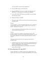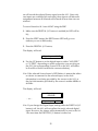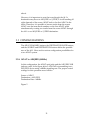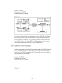
1
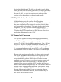
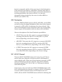
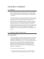
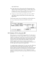
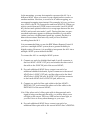
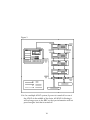
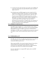
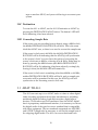
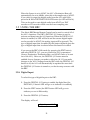
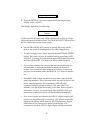
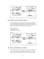
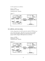
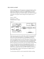
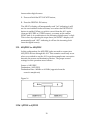
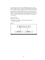
ALESIS
AI-1
Reference Manual
TABLE OF CONTENTS
CHAPTER 1 : INTRODUCTION
1.0 ABOUT THE AI-1 ......................................................................1
1.1 IMPORTANT NOTES ABOUT THIS MANUAL..................3
1.2 OVERVIEW OF MAIN FUNCTIONS.....................................3
1.2A Digital Interface ............................................................3
1.2B Digital Audio Synchronization ....................................4
1.2C Sample Rate Conversion ..............................................4
1.3 BASIC OPERATION .................................................................5
1.3A Source ............................................................................5
1.3B Destination.....................................................................6
1.3C ADAT Channel .............................................................6
1.3D Destination Rate............................................................7
CHAPTER 2 : HOOKUP
2.0 POWER........................................................................................8
2.1 CONNECTION TO ADAT(S) ..................................................8
2.1A Single ADAT .................................................................8
2.1B Multiple ADATs without the BRC...............................9
2.1C Connecting the BRC.......................................................11
2.2 AES/EBU AND S/PDIF..............................................................13
2.2A Connecting an AES/EBU Device ................................13
2.2B Connecting an S/PDIF Device .....................................14
2.3 48 kHz CLOCK OUT .................................................................15
2.4 POWERING-UP .........................................................................15
CHAPTER 3 : TRANSFERRING DIGITAL AUDIO
3.0 AI-1 TO ADAT ...........................................................................16
3.0A Source ............................................................................16
3.0B Selecting Record Tracks ................................................17
3.0C Destination ....................................................................18
3.0D Converting Sample Rate ..............................................18
3.1 ADAT TO AI-1 ...........................................................................18
3.1A Source ............................................................................19
3.1B Selecting Source Tracks ................................................19
3.1C Destination ....................................................................19
3.1D Converting Sample Rate ..............................................19
3.2 USING THE BRC .......................................................................20
3.2A Digital Input..................................................................20
3.2B Bouncing Tracks Between ADATs...............................21
3.2C Recording from AI-1 onto ADAT................................23
1
3.2D BRC Synchronization ...................................................26
3.2E Output ADAT Tracks to AI-1.......................................26
3.2F Bouncing Tracks While Outputting To AI-1 ...............28
3.3 CONFIGURATIONS.................................................................29
3.3A ADAT to AES/EBU (48kHz) .......................................30
3.3B AES/EBU to ADAT (48kHz)........................................30
3.3C AES/EBU to ADAT (44.1kHz to 48kHz) ....................31
3.3D ADAT to AES/EBU (48kHz to 44.1kHz) ....................31
3.3E AES/EBU to ADAT (44.1kHz) .....................................32
3.3F ADAT to S/PDIF (48kHz) ............................................33
3.3G S/PDIF to ADAT (48kHz)............................................33
3.3H S/PDIF to ADAT (44.1kHz to 48kHz) ........................34
3.3I ADAT to S/PDIF (48kHz to 44.1kHz)..........................34
3.3J S/PDIF to ADAT (44.1kHz) ..........................................35
3.3K ADAT to ADAT ............................................................36
3.3L AES/EBU to AES/EBU ................................................37
3.3M S/PDIF to S/PDIF........................................................37
CHAPTER 4 : APPENDICES
4.0 APPENDIX 1
SPECIFICATIONS..................................................................39
4.1 APPENDIX 2
MAINTENANCE/SERVICE INFORMATION ...................41
4.1A Cleaning ........................................................................41
4.1B Maintenance...................................................................41
4.1C Servicing ........................................................................41
2
CHAPTER 1: INTRODUCTION
1.0 ABOUT THE AI-1
Congratulations! You’ve just purchased a powerful tool that will
enhance your ADAT system with incredible digital audio routing
flexibility. The AI-1 Digital Interface and Sample Rate Converter
provides you a way of routing any two ADAT tracks to another
digital recording system, or the other way around, and will convert
the sampling rate as needed. The AI-1 is essential for either
recording digital audio from other sources onto ADAT, or mixing
down a 2 track mix from ADAT to a DAT machine or CD recorder,
all while remaining in the digital domain. Here are some of the
features the AI-1 will provide you:
• High quality, dual-channel digital interface. The AI-1 provides
the connection between AES/EBU, S/PDIF and ADAT digital
formats. With it, you can interface your ADAT digital audio with
various professional and consumer digital audio products (such
as DAT and CD recorders, and digital audio workstations) with
the assurance that the audio never leaves the digital domain.
• Sample rate conversion. The AI-1 can automatically detect the
sampling rate of an incoming digital audio source. When you
want to convert that source, it will transform a 44.1kHz clock to
48kHz, or vice-versa. When routing ADAT digital audio to
another digital destination, the AI-1 can convert the ADAT’s
48kHz sample rate to 44.1kHz (this is especially useful for
creating a mix that’s ready for transfer to CD).
• Sample accurate syncing capabilities. Using ADAT’s exclusive
Proprietary Synchronization Interface, the AI-1 keeps perfect time
with the system. Each ADAT tape is “formatted” with a
proprietary Alesis time code that is much more accurate than
SMPTE or other time code systems. This process time-stamps the
tape to an incredible single-sample accuracy; that is, 1/48,000th of
a second. The AI-1 uses the ADAT’s timecode to keep perfectly
synchronized while transferring digital audio.
• Simple to use. The AI-1’s front panel is extremely easy to
understand and operate. Just select the source, destination,
1
track(s) and the sampling rate…and you’re up and running!
With the BRC Master Remote Control, it’s even easier since all
AI-1 controls are available from the BRC’s Digital I/O edit menu.
• Optic digital interface. ADAT’s Proprietary Multichannel Optic
Digital Interface carries up to eight tracks simultaneously via
optic cable, allowing for perfect, degradation-free digital
dubbing between ADATs. With analog recording, bouncing
tracks or backing up from one multitrack to another loses one
generation, which adds hiss and distortion. With digital
recording, such procedures will produce a “clone” of the
original. This makes it easy to create extra copies of tracks or
safety copies of entire tapes, or make multiple copies for
distribution. The AI-1 lets you choose a pair of tracks from a
single ADAT, and output them to the AES/EBU and S/PDIF
connections. This allows for direct digital connection to and from
other digital audio recorders, DAT recorders, CDs, hard disk
recorders, synthesizers, and more.
• Fast and easy hookup. Connection of the AI-1 is accomplished
via fiber optic digital audio cables, which connect the AI-1 to and
from a single ADAT or multiple ADAT system. Connection to
AES/EBU devices is provided via XLR type connectors.
Connection to S/PDIF devices is provided by both fiber optic
and RCA connectors.
When used with the BRC and multiple ADATs, the Sync Out of
the last ADAT in the chain is connected to the Sync In of the AI1, using a 9 pin style sync cable. The last ADAT’s digital out is
connected to the AI-1’s digital in, and the AI-1’s digital out is
connected to the digital in of the first ADAT, using fiber optic
cables.
When the BRC is turned on, it automatically becomes the
system’s master, and assigns each ADAT an identification
number, from first to last in the chain. The BRC also
automatically checks to see if an AI-1 is connected, and provides
remote control over all of its functions.
• Voltage tolerant power supply. The AI-1 accepts any AC
voltage between 90 and 250 volts.
For more information on digital recording, see Appendix 1 in the
ADAT manual. Appendix 2 in the ADAT manual is a glossary of
2
digital recording terms that may be helpful as you read this manual.
1.1 IMPORTANT NOTES ABOUT THIS
MANUAL
This manual has been designed as a reference to assist the recording
professional in learning the basic operation of the AI-1. All functions
are explained in a clear manner, using step-by-step instructions and
illustrations for setting up and performing various operations.
However, it is assumed that you already have some understanding
of multitrack recording and digital audio in general. It also assumes
you have read the ADAT manual (and the BRC manual, if you are
using the BRC) and comprehend its/their operation.
If you have little or no previous experience with multitrack
recording or working with digital audio, please read the second
manual that comes with the BRC Master Remote Control, entitled
BRC Concepts and Applications. It will give you an understanding
of how an ADAT/BRC/AI-1 system functions in real world
applications, and the types of things you may expect. It explains
why certain features are significant, and how to employ them in
your recording routine. Most importantly, there are simple tutorials
for commonly performed operations, which illustrate exactly how to
put it all together.
In this manual, all connectors, buttons and LEDs are spelled with all
capital letters (such as S/PDIF LED button or SOURCE ADAT
button).
1.2 OVERVIEW OF MAIN FUNCTIONS
Here is a brief rundown of the AI-1’s main functions:
1.2A Digital Interface
The AI-1 provides conversion between ADAT, AES/EBU and
S/PDIF digital formats. This means you can record from other
digital audio devices onto ADAT, or vice-versa, without ever
3
leaving the digital domain. The AI-1 can be used to transfer digital
audio back and forth between DAT machines, CD player/ recorders
and digital audio workstations. Whenever you transfer digital audio
through the AI-1, the result is a perfect, exact duplicate of the
original with no degradation or change in audio quality.
1.2B Digital Audio Synchronization
All digital audio protocols, whether Alesis’ Proprietary
Multichannel Optical Digital Interface or AES/EBU format, transmit
data plus a timing clock that dictates the speed at which the data
will be recorded or played back. This timing clock is related to the
sample rate. The ADAT speed is controlled automatically to
conform to this sample rate whenever its DIGITAL IN LED is lit.
Therefore, the PITCH controls on the ADAT have no effect when
performing digital transfers onto ADAT.
1.2C Sample Rate Conversion
The AI-1 also provides conversion between 48kHz and 44.1kHz
sampling rates. If you are recording onto ADAT from a source that
is running at 44.1kHz, you can either record at the same rate, or
convert it to ADAT’s superior 48kHz sampling rate. One of the best
ways to use ADAT is not only as a multitrack recorder, but as a
mixdown recorder as well, using two tracks to mix to. Using the AI1, you can transfer the two-track mix to DAT or a CD recorder and
simultaneously convert the audio to the required 44.1kHz sample
rate.
Because of its superior sound quality, it is always better to record
onto ADAT at the 48kHz rate, even when the original audio was
recorded at 44.1kHz. Contrary to what many people think,
converting 44.1kHz audio to 48kHz does not change the sound
quality in any way. If, however, you choose to not to convert such
an audio source and record it onto ADAT at 44.1kHz, don’t be
surprised when you play back the ADAT recording and hear the
music a little faster and transposed up a bit. This is because 48kHz is
literally a faster sampling rate than 44.1kHz. When the AI-1 sends
44.1kHz audio to ADAT, the ADAT’s motor slows down to match
the rate of the incoming audio. If you are monitoring other prerecorded tracks on the same machine, you’ll notice that they are
now slower and transposed down.
4
When you play back the audio once it is on ADAT, it will adjust
back to its normal speed and of course sound sharp…roughly 147
cents sharp. If you want to hear the audio on ADAT at the original
pitch and speed, bring the ADAT’s pitch setting down to -147.
Doing so will temporarily show “44.1” in the ADAT’s LED display,
indicating that you are now running at the equivalent to the
44.1kHz rate.
1.3 BASIC OPERATION
When power is first turned on, the AI-1 recalls the most recent mode
of operation (the last mode before power down). The mode is
indicated by the LEDs in the control buttons. These buttons are used
to change the operating mode. The ADAT CHANNEL buttons, the
DESTINATION RATE buttons, and the SOURCE and
DESTINATION buttons define the possible uses of the AI-1.
1.3A Source
The three SOURCE buttons (ADAT, AES/EBU, and S/PDIF) are
used to select the digital source. When one of these buttons is
pressed, its LED will be lit indicating it has been selected. Only one
of the sources can be selected at a time; the corresponding format
input will be enabled, while the others will be disabled.
Here are descriptions of the three Source possibilities:
• ADAT: This allows two tracks from a connected ADAT to be
transmitted to another ADAT, or an AES/EBU or S/PDIF device
(depending on the Destination setting).
• AES/EBU: This allows two tracks from a connected AES/EBU
device to be recorded to an ADAT, or another AES/EBU device,
or an S/PDIF device (depending on the Destination setting).
• S/PDIF: This allows two tracks from a connected S/PDIF device
to be recorded to an ADAT, or another S/PDIF device, or an
AES/EBU device (depending on the Destination setting).
If the selected Source button’s LED lights solid, it means that a
5
device is connected, and the AI-1 is receiving its clock information.
If the selected Source button’s LED flashes, it means that either no
device is connected to the selected input, or the clock information is
not being provided by the source to the AI-1, or the clock
information being provided by the source is neither 48kHz or
44.1kHz (see section 1.3D)
1.3B Destination
The three DESTINATION buttons (ADAT, AES/EBU, and S/PDIF)
are used to select the digital destination. When one of these buttons
is pressed, its LED will be lit indicating it has been selected. Only
one of the destinations can be selected at a time; the corresponding
format output will be enabled, while the others will be disabled.
Here are descriptions of the three Destination possibilities:
• ADAT: This routes the AI-1 output to a connected ADAT for
recording from another ADAT, or an AES/EBU or S/PDIF
device (depending on the Source setting).
• AES/EBU: This routes the AI-1 output to a connected AES/EBU
device for recording from an ADAT, or another AES/EBU
device, or an S/PDIF device (depending on the Source setting).
• S/PDIF: This routes the AI-1 output to a connected S/PDIF
device for recording from an ADAT, or another S/PDIF device,
or an AES/EBU device (depending on the Source setting).
1.3C ADAT Channel
The four ADAT CHANNEL buttons (1/2, 3/4, 5/6, and 7/8) are
used to select two channels on which an ADAT will transmit or
receive digital audio. When one of these buttons is pressed, its LED
will be lit indicating it has been selected. Only the four defined
channel groupings (1 & 2, 3 & 4, 5 & 6, or 7 & 8) may be selected
from the front panel.
In most cases, only one of the four ADAT CHANNEL buttons will
be lit, indicating the two channels on which an ADAT will transmit
or receive audio. If both the Source and Destination are set to
ADAT, all four ADAT CHANNEL buttons will be lit indicating that
6
all eight channels of the ADAT digital bus are transferred.
When using the BRC Master Remote Control, any two channels can
be selected, in which case the ADAT CHANNEL button(s)
corresponding to each selected channel will be lit. Example: if the
BRC is used to select channels 2 and 5 as the ADAT channels, two of
the AI-1’s ADAT CHANNEL buttons (the 1/2 and 5/6 buttons) will
be lit indicating the groupings which contain the selected channels.
1.3D Destination Rate
The DESTINATION RATE buttons (48kHz and 44.1kHz) are used to
select the AI-1’s sample clock output. When one of these buttons is
pressed, its LED will be lit indicating it has been selected.
Only one of the two DESTINATION RATE buttons will be lit to
indicate the output sampling rate. The input rate is automatically set
to match that of the digital source (i.e. whatever rate the source uses,
the AI-1 will automatically detect it and adjust the sampling rate
accordingly).
Here are descriptions of the two Destination Rate possibilities:
• 48kHz: If the source rate is 48kHz, this button’s LED will be lit
indicating the AI-1’s sample rate. If the source rate is 44.1kHz,
pressing the 48kHz button will convert the source’s sample rate
to 48kHz.
• 44.1kHz: If the source rate is 44.1kHz, this button’s LED will be
lit indicating the AI-1’s sample rate. If the source rate is 48kHz,
pressing the 44.1kHz button will convert the source’s sample rate
to 44.1kHz.
Note: If the AI-1’s Destination is set to ADAT and the source’s
sample rate is 48kHz, you will not be able to select the 44.1kHz
button nor alter the AI-1’s output rate. This is because ADAT
already uses a 48kHz sample rate, which is of course superior to
44.1kHz.
If the source rate is neither 48kHz or 44.1kHz, the SOURCE button
LED corresponding to the source (ADAT, AES/EBU or S/PDIF) will
flash, and no sample rate conversion will be allowed. This will be
7
indicated by the fact that both the 48kHz and 44.1kHz LEDs will be
turned off.
8
CHAPTER 2: HOOKUP
2.0 POWER
The AI-1 works with any AC voltage from 90 to 250 volts, 50 to 60
Hz. This eliminates the need for transformers or voltage switches.
The AI-1 comes with a line cord for the destination to which the AI1 is shipped.
The AI-1’s IEC-spec AC cord (do not substitute any other AC cord)
is designed to feed an outlet that includes three pins, with the third,
round pin connected to ground. The ground connection is an
important safety feature designed to keep the chassis of electronic
devices such as the AI-1, BRC and ADAT at ground potential. Unfortunately, the presence of a third ground pin does not always
indicate that an outlet is properly grounded. Use an AC line tester to
determine this. If the outlet is not grounded, consult with a licensed
electrician. When AC currents are suspected of being highly
unstable in VAC and Hz, a professional power conditioner should
be used.
2.1 CONNECTION TO ADAT(S)
2.1A Single ADAT
To connect an Alesis AI-1 module, simply use two fiber optic cables
to connect the digital ins and outs back and forth between the AI-1
and the ADAT (see figure 1). It is not necessary to connect a sync
cable from the ADAT to the AI-1 (or vice-versa) since the ADAT will
provide the AI-1 with clock information via the optic digital
connection when outputting tracks to an AES/EBU or S/PDIF
destination, and the AI-1 will provide clock information to the
ADAT via the optic digital connection when recording from an
AES/EBU or S/PDIF source.
To connect the AI-1 to a single ADAT:
1. Connect one end of a fiber optic cable into the optic digital
output of the ADAT, and the other end to the AI-1’s “ADAT”
9
optic digital input;
Note: If the other end of a fiber optic cable is disconnected and a
signal is being sent through the cable, you will be able to see a
red light at the output. This is an LED and not a laser light, so
you don’t have to worry about damage to your eyes.
2. Connect one end of a fiber optic cable to the AI-1’s “ADAT”
optic digital output, and the other end to the ADAT’s optic
digital input.
This last step creates a loop in the digital bus, and thus allows for
two-way communication between the ADAT and the AI-1.
Figure 1
2.1B Multiple ADATs without the BRC
When using two or more ADATs along with the AI-1, the setup is
basically the same as with a single ADAT, except you’ll need more
cables to accommodate a longer chain of devices (see figure 2). The
ADATs must be synchronized together, using dual male, 9-pin D
connectors. The AI-1 still uses fiber optic cables to connect to the
ADAT’s digital bus, but it does not require connecting the
synchronization cable, since all sync information is conveyed over
the fiber optic cable along with the digital audio.
You might decide to dedicate the AI-1 to just one of the ADATs by
connecting the fiber optic cables between them. This would,
however, limit you to only transmit/receive data between the AI-1
and only that one ADAT, and would prevent you from bouncing
tracks in the digital domain between that ADAT and the other
ADATs in your system. By the way, using a BRC solves all of these
problems.
10
In the meantime, you may be tempted to reconnect the AI-1 to a
different ADAT when you want to route digital audio to tracks on
another machine. However, to avoid a lot of cable swapping, we
recommend swapping tapes instead. For example, let’s say you have
two ADATs, the AI-1 is connected to and from ADAT #1. When you
wish to record from an S/PDIF source onto tracks 9 and 10 (ADAT
#2), the best and quickest solution is to swap tapes between the two
ADATs and record onto tracks 1 and 2. During this time, any prerecorded tracks may appear on different channels of your mixer
(unless you have a sophisticated patch-bay system). But this is a
minor inconvenience that lasts only until you have finished
recording from the AI-1.
It is recommended that you use the BRC Master Remote Control if
you have a multiple ADAT system, due to greater flexibility in
digital routing. However, it is possible to incorporate the AI-1 into a
multiple ADAT system without the BRC.
To connect the AI-1 to a multiple ADAT system:
1. Connect one end of a shielded dual male, 9-pin D connector to
the first ADAT’s SYNC OUT jack, and connect the other end of
the cable to the SYNC IN jack of the second ADAT;
2. For each additional ADAT slave, connect one end of an
additional shielded dual male, 9-pin D connector to the second
ADAT slave’s SYNC OUT jack, and the other end to the third
ADAT slave’s SYNC IN jack. Its SYNC OUT jack then connects
to the fourth ADAT slave’s SYNC IN jack, and so on;
3. Connect one end of a fiber optic cable to the first ADAT’s
DIGITAL OUT, and connect the other end of the cable to the
DIGITAL IN of the second ADAT;
Note: If the other end of a fiber optic cable is disconnected and a
signal is being sent through the cable, you will be able to see a
red light at the output. This is an LED and not a laser light, so
you don’t have to worry about damage to your eyes.
4. For each additional ADAT slave, connect one end of an
additional fiber optic cable to the second ADAT slave’s DIGITAL
11
OUT, and the other end to the third ADAT slave’s DIGITAL IN.
Its DIGITAL OUT then connects to the fourth ADAT slave’s
DIGITAL IN, and so on;
5. Connect one end of a fiber optic cable to the DIGITAL OUT of
the last ADAT in the chain, and connect the other end of the
cable to the AI-1’s “ADAT” optic DIGITAL IN;
6. Finally, connect one end of a fiber optic cable to the AI-1’s
“ADAT” optic DIGITAL OUT, and the other end to the optic
DIGITAL IN of the first ADAT in the system.
This last step creates a loop in the digital bus, and thus allows for
communication between all ADATs and the AI-1.
Figure 2
Note: In a multiple ADAT system, if power is turned off on one of
the ADATs in the middle of the chain, all ADATs following it
will no longer sync to the master ADAT, as the sync information
will not pass through a unit that is turned off.
2.1C Connecting the BRC
When using the BRC, the AI-1’s “ADAT” digital in and out connect
between the last ADAT and the first ADAT in the system. In order
for transfer of digital audio to be possible, the AI-1 requires
synchronization information from the BRC. Synchronization
requires a dual male, 9-pin D connector to connect the last ADAT in
the system to the AI-1. In addition, a BNC-type connector must be
used to connect the 48kHz word clock output of the AI-1 into the
12
BRC. This is required so that the BRC can synchronize to an
AES/EBU or S/PDIF source. Both these connections can be made
while power is on or off, and the ADATs do not need to be turned
on in any particular order (see figure 3).
To connect the AI-1 to a BRC and a multiple ADAT system:
1. Connect one end of a shielded dual male, 9-pin D connector to
the SYNC OUT jack of the last ADAT in the system, and connect
the other end of the cable to the SYNC IN jack of the AI-1;
2. Connect one end of a BNC connector to the 48kHz OUT jack on
the AI-1, and connect the other end of the cable to the 48kHz IN
jack on the BRC;
3. Connect one end of a shielded fiber optic cable into the optic
DIGITAL OUT of the last ADAT in the system, and connect the
other end of the fiber optic cable to the AI-1’s “ADAT” optic
DIGITAL IN;
Note: If the other end of a fiber optic cable is disconnected and a
signal is being sent through the cable, you will be able to see a
red light at the output. This is an LED and not a laser light, so
you don’t have to worry about damage to your eyes.
4. Connect one end of a fiber optic cable to the AI-1’s “ADAT”
optic DIGITAL OUT, and the other end to the optic DIGITAL IN
of the first ADAT in the system.
This last step creates a loop in the digital bus, and thus allows for
communication between all ADATs and the AI-1.
13
Figure 3
Note: In a multiple ADAT system, if power is turned off on one of
the ADATs in the middle of the chain, all ADATs following it
will no longer sync to the BRC, as the sync information will not
pass through a unit that is turned off.
14
2.2 AES/EBU AND S/PDIF
2.2A Connecting an AES/EBU Device
Digital routing to and from an AES/EBU device requires XLR type
cables. These connections can be made while power is on or off, and
the components do not need to be turned on in any particular order.
To connect an AES/EBU device:
1. Connect one end of an XLR cable into the AES/EBU XLR output
of the AI-1, and the other end to the XLR input of the AES/EBU
device;
2. Connect one end of an XLR cable into the AES/EBU XLR output
on the device, and the other end to the AES/EBU XLR input of
the AI-1.
2.2B Connecting an S/PDIF Device
Digital routing to and from an S/PDIF device requires either fiber
optic cables or RCA cables, since the AI-1 provides both these
connectors. These connections can be made while power is on or off,
and the components do not need to be turned on in any particular
order.
To connect an S/PDIF device:
1. Connect one end of a fiber optic cable into the S/PDIF optic
output of the AI-1, OR, connect one end of an RCA cable to the
S/PDIF RCA output of the AI-1 (depending on which
connections are available on the S/PDIF device);
2. Connect the other end of the fiber optic cable to the optic input of
the S/PDIF device, OR, connect the other end of the RCA cable
to the RCA input of the S/PDIF device;
3. Connect one end of a fiber optic cable into the S/PDIF optic
output, OR, connect one end of an RCA cable to the RCA output
on the S/PDIF device;
15
4. Connect the other end of the fiber optic cable to the S/PDIF optic
input, OR, connect the other end of the RCA cable to the RCA
input of the AI-1.
Note: Both the optic and RCA outputs are active when the AI-1’s
Destination is set to S/PDIF. This means you can route digital
audio to two S/PDIF devices simultaneously. When the AI-1’s
Source is set to S/PDIF, the RCA input has priority over the
optic input. If the AI-1 does not detect a device connected to the
RCA input (no sample clock present), it will automatically
switch over and use the optic input. Since the switch is
determined by the presence of a sample clock, you could leave a
device connected to the RCA input, and simply turn its power
off when you wish to use the optic input.
2.3 48 KHZ CLOCK OUT
The 48kHz output signal is a 75 TTL level square wave output,
and is provided via a BNC-type connector. If you are using the BRC
Master Remote Control and plan to record onto ADAT from an
AES/EBU or S/PDIF source, the 48kHz clock out must be connected
to the BRC so that it can be synchronized with the source’s clock
rate.
2.4 POWERING-UP
Normally, the AI-1 does not need to be powered up in any order for
it to work with one or more ADATs. The system can even be
connected while the power is on.
When using the BRC as the system’s master, however, the order in
which the devices are powered-up is important. After all
connections have been made, turn on the power of each ADAT in
the system, turn on the AI-1, and then turn on the BRC.
For more information on using the BRC, please refer to the BRC
Reference Manual.
16
CHAPTER 3: TRANSFERRING
DIGITAL AUDIO
3.0 AI-1 TO ADAT
Recording from an AES/EBU or S/PDIF source through the AI-1
onto ADAT involves a few very simple steps. First, put the ADAT(s)
into Digital In mode by pressing the DIGITAL IN button (the button
will be lit). Next, the digital source must be selected. Then, choose
the tracks you wish to record to. Finally, adjust the sampling rate, if
necessary, to suit your needs.
3.0A Source
On the AI-1, you must set the source to either AES/EBU or S/PDIF,
depending on the actual source you are recording from. This is done
by pressing either the AES/EBU or S/PDIF button in the SOURCE
section of the AI-1 front panel. When pressed, the button will either
light solid or flash to indicate the source you have selected. Only
one of the Source buttons can be selected at a time.
• If the selected Source button’s LED lights solid, it means that an
AES/EBU or S/PDIF device is connected, and the AI-1 is
receiving its clock information. Simultaneously, either the 48kHz
or the 44.1kHz Destination Rate LED will light, indicating the
source’s incoming clock rate.
• If the selected Source button’s LED flashes, it means that either
no device is connected to the selected input, or the clock
information is not being provided by the source to the AI-1, or
the clock information provided by the source is neither 48kHz or
44.1kHz.
Note: If the Source button’s LED flashes, neither one of the
Destination Rate buttons will be lit, indicating that the AI-1 does
not detect any clock information from the source to synchronize
to.
Note: The AI-1 provides two types of connectors for S/PDIF devices.
When the Source is set to S/PDIF, the AI-1 will first look at the
17
RCA input for a sample clock reference. If no sample clock is
found (because no device is connected, or the connected device is
turned off), the AI-1 will then use the fiber optic input.
3.0B Selecting Record Tracks
Once the Source has been determined, the next step is to choose
which ADAT tracks are to be used to record the information. This is
done by pressing one of the four ADAT CHANNEL buttons on the
AI-1 front panel: 1/2, 3/4, 5/6, or 7/8.
When an ADAT CHANNEL button is pressed, its LED will light to
indicate that it has been selected. Pressing the 1/2 button selects
tracks 1 and 2 as the destination, pressing the 3/4 button selects
tracks 3 and 4, and so on.
Since the AI-1’s output is always going to the first ADAT in a
multiple ADAT system, the digital audio can be recorded onto two
of the first eight tracks. In order to route the AI-1’s output through
the first ADAT to another ADAT in the system, a BRC Master
Remote Control must be connected.
It is possible, however, to route digital audio information “through”
the first ADAT to a second ADAT connected to it. To do this, you
must put both ADATs into Digital Input mode (by pressing the
DIGITAL IN button) and put all tracks on the first ADAT into
record-ready. By doing so, the first ADAT will route any digital
audio information it receives back out to the second ADAT, which
in turn can record the information coming from the AI-1. The are
two drawbacks to this method. First, a delay of 3 samples will be
added to the audio on the second ADAT. Second, you will
temporarily be unable to monitor what is on tape on the first ADAT
(since it is monitoring the digital input, and not the tape). Using a
BRC is the only way to route the AI-1’s output to multiple ADATs
without any delay.
Tip: If you are using a multiple ADAT system without a BRC, we
recommend always using the first ADAT in the system to record
from the AI-1. If you wish to record information coming from the
AI-1 onto the tape in ADAT #2 or #3, etc., it is not necessary to
reroute the cables. Instead, you should swap tapes with that
ADAT and the first ADAT. This way, you can monitor the first
18
tape on another ADAT, and you avoid having to reconnect your
system.
3.0C Destination
To route the AI-1 to ADAT, set the AI-1’s Destination to ADAT by
pressing the DESTINATION ADAT button. The button’s LED will
be lit indicating it has been selected.
3.0D Converting Sample Rate
If the source you are recording from is already using a 48kHz clock,
the 48kHz DESTINATION RATE LED will be lit. This is the same
clock that ADAT uses, so there is no need to convert the sample rate.
If the source’s clock rate is 44.1kHz, the 44.1kHz DESTINATION
RATE LED will be lit indicating that the ADAT(s) will synchronize
to the source’s clock. You now have the option of converting the
source’s clock rate to 48kHz, or leaving it at 44.1kHz. Either may be
done by pressing the 48kHz button (the 48kHz DESTINATION
RATE LED will be lit, indicating it has been selected), or simply by
leaving it alone (the 44.1kHz LED will remain lit).
If the source’s clock rate is something other than 48kHz or 44.1kHz,
neither DESTINATION RATE LEDs will be lit, and no sample rate
conversion will be permitted. In this case, the ADAT(s) will still
synchronize to the incoming source’s clock rate.
3.1 ADAT TO AI-1
The AI-1 can route up to two ADAT tracks at a time to other digital
audio recording equipment from other manufacturers, including:
multitrack digital recorders, hard disk recorders, digital effects
devices, CD recorders and DAT machines. Since the ADAT digital
bus is a proprietary multichannel interface, it is necessary to convert
the digital audio of the optic bus into a standard that is compatible
with other equipment. The two standards supported are AES/EBU
and S/PDIF. It might also be necessary to convert the sample rate of
the outgoing digital audio. The AI-1 can convert back and forth
19
between 48kHz and 44.1kHz.
3.1A Source
To route the ADAT to the AI-1, set the AI-1’s Source to ADAT by
pressing the SOURCE ADAT button. The button’s LED will be lit
indicating it has been selected.
Note: When the AI-1’s Source is set to ADAT, the AI-1 links the
ADAT optic input to the ADAT optic output, so that digital
audio is routed from one ADAT to another. This means that, in a
two ADAT system, it is possible to make a digital backup of all
eight tracks of ADAT #2 to ADAT #1, while simultaneously
routing two tracks from ADAT #2 to either an AES/EBU or
S/PDIF device.
3.1B Selecting Source Tracks
You may select a pair of ADAT tracks by pressing one of the four
ADAT CHANNEL buttons (1/2, 3/4, 5/6 or 7/8). If the AI-1’s
Destination is set to AES/EBU or S/PDIF, only one of these four
buttons can be selected. If the Destination is set to ADAT, all four
button’s LEDs will be lit indicating that all eight tracks may be
transmitted/received.
3.1C Destination
To select the AI-1’s output destination, press one of the three
DESTINATION buttons (ADAT, AES/EBU or S/PDIF). The button
will be lit to indicate it has been selected. Only one of the
Destination buttons can be selected at a time.
Note: The AI-1 provides two types of connectors for S/PDIF devices.
When the Destination is set to S/PDIF, the digital audio will be
sent out both S/PDIF outputs (fiber optic and RCA). Therefore, it
is possible to route the AI-1’s output to two S/PDIF devices
simultaneously.
3.1D Converting Sample Rate
20
When the Source is set to ADAT, the AI-1’s Destination Rate will
automatically be set to 48kHz, since this is the sample rate of ADAT.
If you wish to output the digital audio from the AI-1 at 44.1kHz,
press the 44.1kHz DESTINATION RATE button (its LED will be lit).
This can be used to route digital audio from ADAT to a DAT
recorder or CD recorder which uses the lower sampling rate.
3.2 USING THE BRC
The Alesis BRC Master Remote Control can be used to control all of
the AI-1’s functions. The BRC’s DIGITAL I/O button is used to
activate and deactivate the AI-1 functions. When the DIGITAL I/O
button is enabled, its LED will be lit and the current digital inputs
can be recorded to ADAT (the analog inputs will be ignored). The
type of digital input that is enabled by this button depends upon the
type of digital input that is selected when this function is edited.
If you access the BRC’s Edit mode (by pressing the EDIT button)
and select DIGITAL I/O, you can control the AI-1’s parameters
(Source, Destination, Destination Rate, and ADAT tracks to be sent
out of the AI-1). However, the DIGITAL I/O button must be
enabled for any changes you make to affect the AI-1. If you make
changes to the AI-1’s settings from the BRC while the DIGITAL I/O
button is off, the AI-1 will automatically be updated the next time
the DIGITAL I/O button is turned on, so that its setup concurs with
the BRC.
3.2A Digital Input
To select the type of digital input on the BRC:
1. Press the DIGITAL I/O button to enable the digital bus (the
DIGITAL I/O button LED will go on to indicate it is enabled);
2. Press the EDIT button (the EDIT button LED will go on to
indicate you are in Edit mode);
3. Press the DIGITAL I/O button;
The display will read:
Digital input: ADAT
21
… or …
Digital input:
AES/EBU
… or …
Digital input:
S/PDIF
4. Use the UP/DOWN buttons to select the digital input that is to
be the source for recording: “ADAT”, “AES/EBU” or “S/PDIF”
(the corresponding Source LED on the AI-1 will be lit to indicate
the current selection);
5. To exit Edit mode, press the EDIT button (the EDIT LED will
turn off).
Note: If you change the Digital Input setting while the DIGITAL I/O
button is off, the AI-1 will not reflect the newly selected digital
input. However, the change will automatically be sent to the AI1 the next time the DIGITAL I/O button is turned on.
3.2B Bouncing Tracks Between ADATs
The BRC makes it possible to copy tracks between ADATs without
leaving the digital domain. The BRC assumes you have connected
the digital bus correctly between all ADATs in the system (see
section 2.1C). Digital track bouncing is a feature available regardless
of whether an AI-1 is connected, or not.
If the DIGITAL I/O button on the BRC is pressed again when its
digital input display reads "ADAT", you advance to the next
window where you may select which track(s) will be routed to the
digital bus, and thereby sent to any ADAT tracks that are in record
when the DIGITAL I/O button is enabled on the BRC. This allows
for digital track copying and backups.
To digitally bounce tracks from the BRC:
1. Press the EDIT button (the EDIT button LED will go on to
indicate you are in Edit mode);
2. Press the DIGITAL I/O button;
The display will read:
22
Digital input: ADAT
3. Press the DIGITAL I/O button again while the digital input
display reads “ADAT”;
The display will show the following:
Select source with trk
buttons
All the record and input track LEDs will turn off, as they no longer
reflect the record/monitor status. The TRACK INPUT LEDs are now
used to reflect the current source tracks.
4. Use the TRACK SELECT buttons to choose the source tracks
(that is, the tracks to be assigned to the ADAT digital bus);
• To select a single source track, press the desired TRACK SELECT
button. The track will now be enabled and its green Input LED
will be lit. Pressing the same button again will disable that track
and turn off the LED. You may now select a different track.
• If you select a track to be a source that was previously put into
record-enable, it will automatically be taken out of recordenable. Once a track has been selected as a source, it cannot be
put into record-enable while the DIGITAL I/O button is turned
on.
• If multiple track sources are desired, they must come from the
same tape machine. This is because when one track is chosen, the
entire machine becomes the transmitter, while all other
connected ADATs become receivers. Only one ADAT can
transmit over the digital bus at any given time. When a track is
selected as a source, any tracks from other machines that were
previously enabled as sources will be disabled automatically.
• If no source tracks are selected, the ADATs’ digital outputs will
function as digital through connections. This allows for another
digital audio device which uses the ADAT proprietary digital
multichannel bus, such as the Alesis QuadraSynth, to be
connected to the first ADAT’s digital input and thus recorded
23
onto any ADAT connected to the digital bus.
5. Press the EDIT button to exit Edit mode;
6. Press the DIGITAL I/O button to enable the digital bus (the
DIGITAL I/O LED will go on to indicate it is enabled);
7. Use the TRACK SELECT buttons on the BRC to record-enable
the destination tracks;
8. Initiate recording on the BRC.
• The source tracks will be recorded onto the destination tracks in
ascending order.
Example:
If source tracks 1, 2, and 3 are selected and tracks 12, 17, and 24 are
record enabled, then track 1 will be copied to track 12, track 2 to
track 17, and track 3 to track 24.
• If more destination tracks are selected than source tracks, the
source tracks will repeat (cycle).
Example:
If tracks 25 and 29 were added to the destination tracks of the
previous example, then track 1 would be copied to track 25, as well
as to track 12, and track 2 would be copied to track 29, as well as
track 17.
This type of scheme also allows for copying a single track to
multiple tracks.
• A digital source track cannot be selected as a digital destination
track (i.e. digital source tracks will not be allowed to be record
enabled when DIGITAL I/O is enabled).
• When copying digital tracks, any track delays and machine
offsets will be in effect.
3.2C Recording from AI-1 onto ADAT
If either AES/EBU or S/PDIF is selected as the Digital Input, any
ADAT tracks that are record enabled while DIGITAL I/O is turned
24
on will record the selected Source input from the AI-1. Since only
two inputs are available (left and right), these inputs will alternate
assignment between all selected record tracks if more than two are
selected.
To record from the AI-1 onto ADAT using the BRC:
1. Make sure the DIGITAL I/O button is enabled (its LED will be
lit);
2. Press the EDIT button (the EDIT button LED will go on to
indicate you are in Edit mode);
3. Press the DIGITAL I/O button;
The display will read:
Digital input: ADAT
4. Use the UP button to set the digital input to either “AES/EBU”
or “S/PDIF”, depending on which connection you are using on
the AI-1 (the corresponding Source LED on the AI-1 will either
be lit solid or flash to indicate the current selection);
Note: If the selected Source button’s LED flashes, it means that either
no device is connected to the selected input, or the clock
information is not being provided by the source to the AI-1, or
the clock information provided by the source is neither 48kHz or
44.1kHz.
The display will read:
Digital input:
AES/EBU
… or …
Digital input: S/PDIF
Note: If you change the Digital Input setting while the DIGITAL I/O
button is off, the AI-1 will not reflect the newly selected digital
input. However, the change will automatically be sent to the AI1 the next time the DIGITAL I/O button is turned on.
25
5. Press the DIGITAL I/O button twice;
The display will show the following:
AI-1 Destination
ADAT
6. If the AI-1 Destination is set to either “AES/EBU” or “S/PDIF”,
use the DOWN button to set the AI-1’s Destination to “ADAT”.
7. Press the DIGITAL I/O button again to access the AI-1’s clock
rate;
The display will show the following:
AI-1 Dest Rate
48K
This determines the output sample rate of the AI-1. When the
Digital Input is changed, the AI-1 automatically looks for the clock
source. When it sees it, the clock rate is determined.
• If the source’s clock rate is 44.1kHz, then the 44.1kHz LED on the
AI-1 will be lit. The Destination Rate can be set to either 44.1kHz
or 48kHz.
• If the source’s clock rate is 48 kHz, the 48kHz LED on the AI-1
will be lit. However, the Destination Rate will have no effect on
the AI-1, since you can only record a 48kHz source to ADAT at
48kHz.
• If the source’s clock is neither 48kHz nor 44.1kHz, neither LED
will light and no conversion will take place. Therefore, the
Destination Rate setting on the BRC will have no effect on the
AI-1.
8. Use the UP/DOWN buttons to select the AI-1’s Destination Rate
(48K or 44.1K).
Important: When recording audio from AES/EBU or S/PDIF, the
ADAT(s) derive their clock source from the incoming digital
audio via the optic digital bus, and are therefore perfectly in sync
26
with the incoming source. However, it is important to note that
the BRC also requires a 48kHz clock in order to be synchronized
to the incoming digital signal (see section 3.2D). Since the BRC
has nothing to do with the ADAT’s optic digital bus, you will
need to route clock information from the AI-1 to the BRC by
connecting the AI-1’s 48kHz output to feed the BRC’s 48kHz
input (see section 2.1C).
9. Press the EDIT button to exit Edit mode (the EDIT LED will turn
off);
10. Use the TRACK SELECT buttons on the BRC to record-enable
the destination tracks;
11. Initiate recording on the BRC.
• The source tracks will be recorded onto the destination tracks in
ascending order (see previous section 3.2B regarding the
guidelines for selecting record tracks).
3.2D BRC Synchronization
It is important that, when recording from AES/EBU or S/PDIF, the
BRC is receiving synchronization information from the AI-1’s 48kHz
clock out. When recording onto ADAT from an AES/EBU or
S/PDIF source, the BRC’s 48kHz, SMPTE, and MIDI outputs will
not be usable if no timing reference is provided by the AI-1. While
the BRC is synchronizing to the AI-1’s 48kHz clock, all of the BRC’s
sync outputs will be usable. However, it is up to you to insure that
the AES/EBU or S/PDIF digital audio signal is synchronous to the
clock source that is connected to the BRC by providing it with clock
information.
When the DIGITAL I/O button is turned on and the digital input
has been set to either AES/EBU or S/PDIF, the EXT SYNC button
on the BRC will automatically turn on and disable the pitch controls
(the Pitch display will read “ – – – ”). The EXT SYNC’s clock source
will be set to 48kHz. It is possible, however, to disable the EXT
SYNC button by pressing it without turning off the DIGITAL I/O
button. This is not recommended, since the BRC would no longer be
in perfect sync with the digital source’s clock rate, which could
27
result in clicks in the audio.
For more information on 48kHz clock, see sections 2.1C and 2.3.
3.2E Output ADAT Tracks to AI-1
If the BRC is in Edit mode (the EDIT button is lit), and the DIGITAL
I/O button is pressed a third time when the Digital Input is set to
"ADAT", (or if it is pressed a second time when set to "AES/EBU" or
"S/PDIF"), you may select the source tracks that will output to the
AI-1. When the DIGITAL I/O button is pressed again, you may
select the AI-1 destination, which can be either “ADAT”,
“AES/EBU” or “S/PDIF”. You may also set the destination clock
rate for the AI-1 to either 48kHz or 44.1kHz, thus performing sample
rate conversion.
To route ADAT tracks to the AI-1 from the BRC:
1. Press the EDIT button (the EDIT button LED will go on to
indicate you are in Edit mode);
2. Press the DIGITAL I/O button;
3. Use the UP/DOWN buttons to select “ADAT” as the Digital
Input you wish to use as a source for recording;
4. Press the DIGITAL I/O button twice;
The display will show the following:
Select tracks to
output to AI-1
All the record and input track LEDs will no longer reflect the
record/monitor status. The TRACK INPUT LEDs will now reflect
the current source tracks to be output to the AI-1.
5. Use the TRACK SELECT buttons to select the tracks to output to
the AI-1;
• To select a single source track, press the desired TRACK SELECT
button. The track will now be enabled and its green LED will be
28
lit. Pressing the same button again will disable that track and
turn off the LED. You may now select a different track.
• A maximum of two tracks may be selected at a time, and they
must come from the same tape machine.
• When a track is selected as a source, any tracks from other
machines that were previously selected will become disabled. If
no tracks are selected, the AI-1's digital output will be silent. If
only one track is selected, it will be routed to the left output of
the AI-1, and the right output will be silent.
While the Digital Input is set to “ADAT”, ADAT tracks can be
output to the AI-1 even when the DIGITAL I/O button is off,
allowing you to monitor through the ADATs analog inputs and out
the AI-1. However, if the Digital Input is set to “AES/EBU” or
“S/PDIF”, the selected tracks will only output to the AI-1 when the
DIGITAL I/O button is turned off. This is because the AI-1 can only
work one-way. Therefore, it cannot be sending audio from ADAT to
S/PDIF while simultaneously converting AES/EBU onto ADAT.
6. Press the DIGITAL I/O button again;
The display will show the following:
AI-1 Destination
ADAT
7. Use the UP/DOWN buttons to select the AI-1’s destination
(AES/EBU or S/PDIF).
Note: Tracks selected to be output to the AI-1 will only be routed as
such if the AI-1 destination is set to either “AES/EBU” or
“S/PDIF”, since setting the destination to “ADAT” means you
wish to bounce to other ADAT tracks.
8. Press the DIGITAL I/O button again;
The display will show the following:
AI-1 Dest Rate
48K
29
9. Use the UP/DOWN buttons to select the AI-1’s Destination Rate
(48K or 44.1K). This determines the output sample rate of the AI1.
3.2F Bouncing Tracks While Outputting To AI-1
The digital output routed from ADAT to the AI-1 will always be
active, whether DIGITAL I/O is turned on or off. However, if
DIGITAL I/O is on and “ADAT” has been selected as the digital
input, you are still capable of performing track bouncing among
your ADATs. However, the tracks selected for output to the AI-1
must be the same or higher than the highest numbered track
selected as source or record enabled. For example, if you have three
ADATs (24 tracks) and you wish to output tracks 15 and 16 (from
ADAT #2) through the AI-1 to an AES/EBU device, it is still
possible to simultaneously bounce digital audio between ADAT
tracks 1 and 14.
Figure 4
The reason for this restriction has to do with the fact that there is a
single 8-channel digital audio bus. Each ADAT can either be
sending its own tracks out on the digital bus, or “echoing” what it
receives on its digital input. The digital connections of the slave
units are serial (i.e. the units are chained together with unit #1’s
digital output connected to unit #2’s digital input, unit #2’s digital
output connected to unit #3’s digital input, and so on). When you
have an ADAT become a source so it outputs its tracks on the digital
bus, any other ADAT before it in the digital bus chain that is
transmitting its tracks will not be routed to the ADATs connected
30
after it.
However, it is important to note that even though the AI-1’s
destination may be set to AES/EBU or S/PDIF, it is still sending all
eight channels of the source ADAT back to the first ADAT in the
chain. Therefore, it is possible to bounce tracks from the source
ADAT onto the same track numbers on the first ADAT, while
simultaneously routing two tracks from the source ADAT through
the AI-1 to an AES/EBU or S/PDIF destination.
3.3 CONFIGURATIONS
The ADAT CHANNEL buttons, the DESTINATION RATE buttons,
and the SOURCE and DESTINATION buttons define the possible
uses of the AI-1. Here are the various configuration possibilities for
a two ADAT system.
3.3A ADAT to AES/EBU (48kHz)
In this configuration, the ADAT optic jacks and the AES/EBU XLR
jacks are used. In the figure below, ADAT #2 is transmitting to an
AES/EBU device using a 48kHz sampling rate. The proper control
settings for this operation are as follows:
Source = ADAT
Destination = AES/EBU
Destination Rate = 48kHz
Figure 5
31
Note: Even when the AI-1’s destination is set to AES/EBU, the
digital bus being received from the last ADAT is routed through
back to the first ADAT. Therefore, it is possible to bounce audio
from the last ADAT back to the first ADAT, while simultaneously
routing two tracks from the last ADAT to an AES/EBU device.
3.3B AES/EBU to ADAT (48kHz)
In this configuration, the ADAT optic jacks and the AES/EBU XLR
jacks are used. In the figure below, ADAT #1 is receiving from an
AES/EBU device using a 48kHz sampling rate. The proper control
settings for this operation are as follows:
Source = AES/EBU
Destination = ADAT
Destination Rate = 48kHz
Figure 6
3.3C AES/EBU to ADAT (44.1kHz to 48kHz)
32
In this configuration, the ADAT optic jacks and the AES/EBU XLR
jacks are used. In the figure below, ADAT #1 is receiving from an
AES/EBU device using a 44.1kHz sampling rate being converted to
48kHz. The proper control settings for this operation are as follows:
Source = AES/EBU
Destination = ADAT
Destination Rate = 48kHz
Figure 7
3.3D ADAT to AES/EBU (48kHz to 44.1kHz)
In this configuration, the ADAT optic jacks and the AES/EBU XLR
jacks are used. In the figure below, ADAT #2 is transmitting to an
AES/EBU device using a 44.1 kHz sampling rate. The proper
control settings for this operation are as follows:
Source = ADAT
Destination = AES/EBU
Destination Rate = 44.1kHz
Figure 8
33
3.3E AES/EBU to ADAT (44.1kHz)
In this configuration, the ADAT optic jacks and the AES/EBU XLR
jacks are used. In the figure below, ADAT #1 is receiving from an
AES/EBU device using a 44.1kHz sampling rate without
conversion. The proper control settings for this operation are as
follows:
Source = AES/EBU
Destination = ADAT
Destination Rate = 44.1kHz
Figure 9
3.3F ADAT to S/PDIF (48kHz)
In this configuration, the ADAT optic jacks and the S/PDIF jacks are
used. In the figure below, ADAT #2 is transmitting to an S/PDIF
device using a 48kHz sampling rate. The proper control settings for
this operation are as follows:
34
Source = ADAT
Destination = S/PDIF
Destination Rate = 48kHz
Figure 10
Note: Even when the AI-1’s destination is set to S/PDIF, the digital
bus being received from the last ADAT is routed through back to
the first ADAT. Therefore, it is possible to bounce audio from the
last ADAT back to the first ADAT, while simultaneously routing
two tracks from the last ADAT to an S/PDIF device.
3.3G S/PDIF to ADAT (48kHz)
In this configuration, the ADAT optic jacks and the S/PDIF jacks are
used. In the figure below, ADAT #1 is receiving from an S/PDIF
device using a 48kHz sampling rate. The proper control settings for
this operation are as follows:
Source = S/PDIF
Destination = ADAT
Destination Rate = 48kHz
Figure 11
35
3.3H S/PDIF to ADAT (44.1kHz to 48kHz)
In this configuration, the ADAT optic jacks and the S/PDIF jacks are
used. In the figure below, ADAT #1 is receiving from an S/PDIF
device using a 44.1kHz sampling rate being converted to 48kHz. The
proper control settings for this operation are as follows:
Source = S/PDIF
Destination = ADAT
Destination Rate = 48kHz
Figure 12
3.3I ADAT to S/PDIF (48kHz to 44.1kHz)
In this configuration, the ADAT optic jacks and the S/PDIF jacks are
used. In the figure below, ADAT #2 is transmitting to an S/PDIF
device using a 44.1kHz sampling rate. The proper control settings
36
for this operation are as follows:
Source = ADAT
Destination = S/PDIF
Destination Rate = 44.1kHz
Figure 13
3.3J S/PDIF to ADAT (44.1kHz)
In this configuration, the ADAT optic jacks and the S/PDIF jacks are
used. In the figure below, ADAT #1 is receiving from an S/PDIF
device using a 44.1kHz sampling rate without conversion. The
proper control settings for this operation are as follows:
Source = S/PDIF
Destination = ADAT
Destination Rate = 44.1kHz
Figure 14
37
3.3K ADAT to ADAT
In this configuration, the AI-1 becomes a transparent link in a daisychain. In the figure below, ADAT #2 is transmitting all 8 tracks to
ADAT #1, in addition to all 8 tracks of ADAT #1 being routed to
ADAT #2. The sample rate is fixed at 48kHz, and cannot be changed
to 44.1kHz. The proper control settings for this operation are as
follows:
Source = ADAT
Destination = ADAT
Destination Rate = 48kHz
Figure 15
When bouncing tracks from ADAT #2 to ADAT #1, the first ADAT
is the master and must provide sync information to ADAT #2.
However, when the first ADAT is put into DIGITAL IN mode, it
looks at the digital source for its clock information, instead of using
its own internal clock. For this scenario to work, it is necessary that
the first ADAT use its own internal clock. When the DIGITAL IN
button is turned on, it can be set to one of two modes: either looking
for sync information from the incoming digital audio (normal
setting) or to ignore the incoming sync information and use its own
internal clock. Therefore, when recording from ADAT #2 onto
ADAT #1, you must switch the first ADAT’s DIGITAL IN mode to
the “internal clock” setting so that it ignores the digital source’s
clock and provides it own.
To set the master ADAT to use its internal clock while recording
38
from another digital source:
1. Press and hold the SET LOCATE button;
2. Press the DIGITAL IN button;
The ADAT’s display will momentarily read “int” indicating it will
use its own internal clock at all times, even when the DIGITAL IN
button is enabled. When you wish to record from the AI-1 again
(from an AES/EBU or S/PDIF source), you must set the master
ADAT back so it synchronizes to the incoming digital source’s clock.
This is done by repeating the steps above (the ADAT’s display will
momentarily read “diG” indicating it will use the incoming clock
from the digital source).
3.3L AES/EBU to AES/EBU
In this configuration, the AES/EBU jacks are used to connect two
AES/EBU devices through the AI-1. This scenario would only occur
when you wished to use the AI-1 to perform sample rate conversion
between the source and destination devices. The proper control
settings for this operation are as follows:
Source = AES/EBU
Destination = AES/EBU
Destination Rate = 48kHz or 44.1kHz (opposite from the
source’s sample rate)
Figure 16
3.3M S/PDIF to S/PDIF
39
In this configuration, either the S/PDIF fiber optic jacks or RCA
jacks (or both) are used to connect two S/PDIF devices through the
AI-1. In the figure below, S/PDIF device #1 is connected to the RCA
jacks of the AI-1, while S/PDIF device #2 is connected to the fiber
optic jacks. This scenario would only occur when you wished to use
the AI-1 to perform sample rate conversion between the source and
destination devices. The proper control settings for this operation
are as follows:
Source = S/PDIF
Destination = S/PDIF
Destination Rate = 48kHz or 44.1kHz (opposite from the
source’s sample rate)
Figure 17
40
CHAPTER 4: APPENDICES
4.0 APPENDIX 1: SPECIFICATIONS
Number of Digital Audio
Channels:
ADAT:
AES/EBU, S/PDIF:
Sample Clock Input range:
8
2
48 kHz nominal. User variable
from 50.8 to 40.4kHz (+1, -3
semitones).
Digital Inputs/Outputs:
Connectors:
Four EIAJ fiber optic jacks (2
inputs, 2 outputs); two RCA
connectors (1 input, 1 output); two
XLR connectors (1 input, 1 output)
Communications
Protocol:
Alesis Fiber optic Multichannel (8
tracks); AES/EBU (2 channels);
S/PDIF (2 channels)
Front Panel Controls and
Indicators:
Push buttons with LED indicators
for ADAT Channel (1/2, 3/4, 5/6,
& 7/8), Destination Rate (48kHz,
44.1kHz), Source and Destination
(ADAT, AES/EBU, S/PDIF); AC
power switch
Rear Panel Controls and
Connectors:
Two 9 pin D-Sub connectors for
Sync In and Sync Out; Four EIAJ
fiber optic jacks for ADAT Digital
In and Out and S/PDIF Digital In
and Out; Two RCA jacks for
S/PDIF In and Out; Two XLR
connectors for AES/EBU Digital
In and Out; One BNC connector
for 48kHz Word Clock Out; IECspec AC cord connector.
90-250 VAC, 50–60 Hz, 50 W max.
Power Requirements:
41
Dimensions (H x W x D):
Weight:
Shipping Weight:
Accessories Included:
1-3/4" x 19" x 6-1/4"
4.5 lbs (2 kg)
7 lbs (3.1 kg)
IEC style AC power cord
Owner’s Manual
RMB Remote Meter Bridge
BRC Master Remote Control
Optional Accessories:
42
4.1 APPENDIX 2: MAINTENANCE/SERVICE
INFORMATION
4.1A Cleaning
Disconnect the AC cord, then use a damp cloth to clean the AI-1’s
metal and plastic surfaces.
4.1B Maintenance
Here are some tips for preventive maintenance:
• Periodically check the AC cord for signs of fraying or damage.
• Unplug the AI-1 when not in use for extended periods of time.
4.1C Servicing
DO NOT ATTEMPT REPAIRS YOURSELF. THERE ARE NO USER
SERVICEABLE PARTS INSIDE THE AI-1. Refer all servicing to
Alesis. YOU MUST FIRST CONTACT ALESIS TO OBTAIN A
RETURN AUTHORIZATION NUMBER BEFORE THE UNIT IS
RETURNED TO ALESIS.
43