1
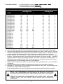
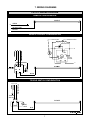
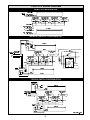
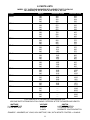
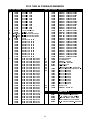
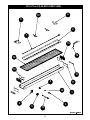
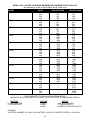
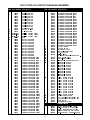
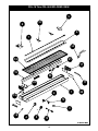
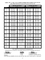
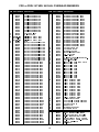
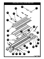
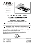
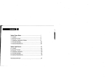
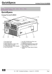
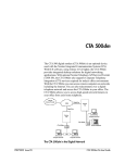
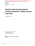
R INSTALLATION AND OPERATING INSTRUCTIONS Models: FD, FDD, FDL & FDDL OVERHEAD WARMERS INTENDED FOR OTHER THAN HOUSEHOLD USE RETAIN THIS MANUAL FOR FUTURE REFERENCE UNIT MUST BE KEPT CLEAR OF COMBUSTIBLES AT ALL TIMES ! FOR YOUR SAFETY: Do not store or use gasoline or other flammable vapors and liquids in the vicinity of this or any other appliance. ! ! WARNING: Improper installation, adjustment, alteration, service or maintenance can cause property damage, injury or death. Read the Installation, Operating and Maintenance Instructions thoroughly before installing or servicing this equipment. ! Initial heating of unit may generate smoke or fumes and must be done in a well ventilated area. Overexposure to smoke or fumes may cause nausea or dizziness. This equipment has been engineered to provide you with year-round dependable service when used according to the instructions in this manual and standard commercial kitchen practices. ANSI/NSF4 Phone: Fax: Toll Free: Website: E-mail: P/N 70400000 Rev. 3/06 (214) 421-7366 (214) 565-0976 (800) 527-2100 www.apwwyott.com [email protected] APW WYOTT 729 Third Avenue Dallas, TX 75226 1 TABLE OF CONTENTS SECTION PAGE ITEM 1 Owner’s Information General Information Installation Instructions General Operation Instructions Warranty Information 2 2 3 4 4 2 Important Safety Information 4 3 Specifications Electrical Dimensions 4 4 5 4 Operation Operating Instructions 6 6 5 Cleaning General Cleaning Instructions 6 6 6 Troubleshooting 6 7 Wiring Diagrams. FD Wiring Diagrams FDL Wiring Diagrams FDD Wiring Diagrams FDDL Wiring Diagrams 7 7 8 9 10 8 Parts Lists FD Replacement Parts FDL Replacement Parts FDD or FDDL Replacement Parts 11 11 14 17 9 Warranty 20 1. OWNERS INFORMATION General Information: 1. 2. 3. 4. 5. Always clean equipment thoroughly before first use. (See general cleaning instructions). Check rating label for your model designation and electrical rating. For best results, use stainless steel countertops. All dimensions in parenthesis in centimeters unless noted. APW Wyott Overhead Foodwarmers are constructed from high quality stainless steel and available in lengths from 18" to 96”. Utilizing a metal sheath-heating element with a specially designed reflector, these units give uniform heat over the entire holding surface. 6. In Europe, contact an APW Wyott authorized service agency for replacement light bulbs. Installation Instructions: A. Always clean equipment thoroughly before first use (See cleaning instructions). B. Provide the following clearances around foodwarmer: 2 Do not install closer than: A = Minimum clearance (in inches) to Bottom Surface of unit from Tabletop B = Minimum clearance (in inches) to Back of unit. C = Minimum clearance (in inches) to Sides of unit. CLEARANCES FOR OVERHEADS MODEL FDD/FDDL-18 FDD/FDDL-24 FDD/FDDL-30 FDD/FDDL-36 FDD/FDDL-42 FDD/FDDL-48 FDD/FDDL-54 FDD/FDDL-60 FDD/FDDL-66 FDD/FDDL-72 FDD/FDDL-84 FDD/FDDL-96 FD/FDL-18 FD/FDL-24 FD/FDL-30 FD/FDL-36 FD/FDL-42 FD/FDL-48 FD/FDL-54 FD/FDL-60 FD/FDL-66 FD/FDL-72 FD/FDL-84 FD/FDL-96 A HIGH WATTAGE B C A LOW WATTAGE B C 28 28 28 28 28 28 28 28 28 28 N/A N/A 16 16 16 16 16 16 16 16 16 16 N/A N/A 12 12 12 12 12 12 12 12 12 12 N/A N/A 2 2 2 2 2 2 2 2 2 2 N/A N/A 2 2 2 2 2 2 2 2 2 2 N/A N/A 2 2 2 2 2 2 2 2 2 2 N/A N/A 24 24 24 24 24 24 24 24 24 24 24 24 16 16 16 16 16 16 16 16 16 16 16 16 12 12 12 12 12 12 12 12 12 12 12 12 2 2 2 2 2 2 2 2 2 2 2 2 2 2 2 2 2 2 2 2 2 2 2 2 2 2 2 2 2 2 2 2 2 2 2 2 C. Consult foodwarmer rating label for model designation and correct operating voltage and amperage. D. Ceiling mounting brackets are provided with each foodwarmer for chain or shelf mounting. Remove brackets form packaging and screws from ends of foodwarmer to attach brackets. Use four #10 screws or studs with locknuts for shelf mounting. For chain mounting, use #14 jack chain and “S” hooks. E. Remote switches are recommended. Longer switch life will result from cooler switch mounting locations. Optional stainless steel remote toggle and infinite switch box kits are available. Installation of remote switch box by service personnel requires 7/8" conduit, 1/4" push-on terminals, and no. 14 AWG copper wire suitable for at lest 90ºC. Mount remote box to flat surface with two #10 screws or studs with locknuts. All wires marked as shown on wiring diagram. F. Optional tubular stands are available for permanently mounting foodwarmers to non-combustible countertops. G. Optional portable legs are available for foodwarmers for use over non-combustible countertops. H. Installation of cord sets by service personnel should utilize the strain relief, grounding stud, and porcelain wire nuts provided with foodwarmers. I. If unit is supplied with a power cord, the appliance must be positioned so that the plug is accessible. ! NOTE: TO AVOID BURNING OR CHARRING OF MATERIALS IN THE SURFACE BELOW THE FOODWARMER USE ONLY ABOVE AN ALL-METAL STRUCTURE SUCH AS ATABLE OR COUNTERTOP. SEE MINIMUM CLEARANCE CHARTABOVE. REMOTE SWITCHES ARE RECOMMENDED FOR UNDER SHELF MOUNTING. LONGER SWITCH LIFE WILL RESULT FROM COOLER SWITCH MOUNTING LOCATIONS. 3 ! General Operation Instructions: 1. All foodservice equipment should be operated by trained personnel. 2. Do not allow your customers to come in contact with any surface labeled “CAUTION HOT”. 3. Never hold food below 150°F (66°C). Warranty Information: Reliability Backed By APW Wyott’s Warranty: All APW Wyott Overhead Warmers are backed by a one year parts and labor warranty, including On-Site Service calls within 50 miles of authorized service technicians. Service Information: Service Hotline (800) 733-2203 2. SAFETY INFORMATION APW Wyott Overhead Warmers are designed, built and sold for commercial use and should be operated by trained personnel only. Clearly post all CAUTIONS, WARNINGS and OPERATING INSTRUCTIONS near each unit to insure proper operation and to reduce the chance of personal injury and/or equipment damage. Always disconnect power before servicing the Overhead Warmer. Surfaces will remain hot after power has been turned off. Allow unit to cool before cleaning or servicing. Never clean the Overhead Warmer by immersing it in water. The Overhead Warmer is not protected against water jets; DO NOT CLEAN OVERHEAD WARMER WITH A WATER JET. Always clean equipment before first use. 3. SPECIFICATIONS Electrical: A. Single-phase operation at 120, 208, 230, and 240 volts. (See label on each unit). B. Field-wired units provided with 7/8" conduit hole, 6" long leads, and porcelain wire nuts. For supply connections, use minimum no. 14 AWG copper wires suitable for at least 90ºC. C. U.S. cord-connected units provided with following plug configuration: 1. 120 volt up to 1440 watts = NEMA 5-15P; 120 volt up to 1920 watts = NEMA 5-20P 2. 208 volt up to 2496 watts = NEMA 6-15P; 208 volt up to 3328 watts = NEMA 6-20P 3. 240 volt up to 2880 watts = NEMA 6-15P; 240 volt up to 3840 watts = NEMA 6-20P D European cord-connected units provided with following plug configuration: 1. Continental Europe230 volt up to 3600 watts = Schuko CEE7/7 2. UK230 volt up to 2930 watts = Bs1363 If the supply cord is damaged, an authorized service agent or a similarly qualified person must replace it to avoid a hazard or voiding the warranty. 4 ! WARNING: ELECTRICAL SHOCK HAZARD. FAILURE TO FOLLOW THE INSTRUCTIONS IN THIS MANUAL COULD RESULT IN SERIOUS INJURY OR DEATH. ! Electrical Ground is required on this appliance. Do not modify the power supply cord plug. If it does not fit into the outlet, have the proper outlet installed by a qualified electrician Do not use an extension cord with this appliance. Check with a qualified electrician if you are unsure as to whether the appliance is properly grounded. Overall Dimensions: FD MODELS POWER LEADS .875 [ 2.22 ] CONDUIT HOLE 6.000 [ 15.24 ] 6.923 [ 17.58] OVERHEAD WARMER LENGTH 18.00 [45.72] TO 72.00 [182.88] MOUNTING BRACKETS .75 [ 1.91] 3.58 [ 9.09 ] RATING LABEL PILOT LIGHT 1.00 [ 2.55 ] TOGGLE OR INFINITE SWITCH FDD, FDDL MODELS FDL MODELS 9.125 [ 23.18 ] 15.125 [ 38.42 ] 10.048 [ 25.52 ] 16.971 [ 43.11] TUBULAR STAND KIT PORTABLE LEG KIT FOR USE ABOVE NONCOMBUSTIBLE SURFACE FOR INSTALLATION ABOVE NONCOMBUSTIBLE SURFACE 1.00[2.54] SQUARE S/S TUBING 16.00 [ 40.64 ] 16.00 [ 40.64 ] 18.50 [ 46.99 ] 18.50 [46.99 ] 1.00[2.54] SQUARE S/S TUBING 5/16 -18 STUD MOUNT OVERHEAD WARMER LENGTH + 2.06[5.23] OVERHEAD WARMER LENGTH + 1.06[2.7] 5 11.00 [27.94] 11.27 [28.63] 4. Operation A. All foodservice equipment should be operated by trained personnel. B. Do not allow your customers to come in contact with any surface labeled “CAUTION HOT”. C. Switch on unit. Place precooked product under heat source. Maximum heat coverage equivalent to unit length. D. Never hold food below 150ºF. 5. Cleaning General Cleaning Instructions: A. Never clean any electrical unit by immersing it in water. Turn off before surface cleaning. B. Never clean any electrical unit using water jets. C. Disconnect power before cleaning or servicing units. All service should be performed by an APW authorized service agency. D. Clean unit daily. Use warm, soapy water. Mild cleansers and non-abrasive pads may be used to remove baked-on food. 6. Troubleshooting A. Always ask and check: 1. Is the unit connected to a live power source? 2. Check the circuit breaker. 3. Is the power switch on and pilot light illuminating? 4. Check the rating label. Is the unit operating on proper voltage? B. If the above checks out, and problems still exist, call an APW Wyott authorized service agency. C. All service should be performed by an APW Wyott authorized service agency. 6 7. WIRING DIAGRAMS FD18-72 WIRING DIAGRAM REMOTE CONFIGURATION ELEMENT G GREEN 120V: WHITE 200-240V: BLUE BROWN INFINITE CONTROL CONFIGURATION HEATING ELEMENT DISPLAY LIGHT INDICATOR LIGHT L2 120V: WHITE BROWN GREEN L2 200-240V: BLUE L1 L2 G H2 H1 PILOT L1 EGO INFINITE CONTROL L1 INFINITE CONTROL P L1 L2 H1 H2 ELEMENT PILOT LIGHT BLUE BROWN TOGGLE SWITCH CONFIGURATION 120V: WHITE 200-240V: BLUE GREEN BROWN G L1 L2 TOGGLE SWITCH ELEMENT PILOT LIGHT BLUE BROWN 67177 REV-11/2001 7 FDL18-72 WIRING DIAGRAM REMOTE CONFIGURATION ONE LAMPHOLDER 18,24,30 MODELS TWO LAMPHOLDERS 36,42,48,54 MODELS BLACK WHITE BLACK WHITE BLUE 6 4 120V: WHITE 200-240V: BLUE L1 5 BROWN G 1 N/L2 2 L1 3 FOUR LAMPHOLDERS 84,96 MODELS BLACK WHITE BLUE 6 7 LABELS N/L2 THREE LAMPHOLDERS 60,66,72 MODELS WHITE BLACK BLUE 6 7 7 ELEMENT GREEN 120V: WHITE 200-240V: BLUE BROWN INFINITE CONTROL CONFIGURATION HEATING ELEMENT DISPLAY LIGHT INDICATOR LIGHT L2 L2 H2 H1 L1 PILOT FOUR LAMPHOLDERS EGO INFINITE CONTROL 84,96 MODELS L1 120V: WHITE LABELS 200-240: BLUE N/L2 L1 G WHITE ONE LAMPHOLDER TWO LAMPHOLDERS THREE LAMPHOLDERS 18,24,30 MODELS 36,42,48,54 MODELS 60,66,72 MODELS BLACK BROWN GREEN WHITE 1 BLUE BLACK BLACK WHITE BLUE 8 3 L1 L2 BLACK BLUE 8 9 9 2 WHITE BLUE 8 9 6 INFINITE P ELEMENT CONTROL H1 7 PILOT H2 5 LIGHT 4 BLUE BROWN BROWN TOGGLE SWITCH CONFIGURATION ONE LAMPHOLDER 18,24,30 MODELS LABELS 120V: WHITE 200-240V: BLUE N/L2 L1 G TWO LAMPHOLDERS 36,42,48,54 MODELS THREE LAMPHOLDERS 60,66,72 MODELS FOUR LAMPHOLDERS 84,96 MODELS BROWN GREEN WHITE 1 BLACK BLACK WHITE BLUE 8 9 TOGGLE SWITCH 2 WHITE BLUE 8 9 6 ELEMENT 7 5 4 PILOT LIGHT BLUE BROWN BROWN 8 WHITE BLUE 9 BLUE 3 BLACK 8 BLACK FDD18-72 WIRING DIAGRAM REMOTE CONFIGURATION ELEMENT 120V: WHITE 200-240V: BLUE LABELS N/L2 BROWN L1 GREEN G ELEMENT 120V: WHITE 200-240V: BLUE N/L2 BROWN L1 INFINITE CONTROL CONFIGURATION ELEMENT P L1 L2 H1 H2 PILOT LIGHT LABELS N/L2 L1 G BLUE 200-240V: BLUE 120V: WHITE BROWN HEATING ELEMENT DISPLAY LIGHT BROWN INDICATOR LIGHT GREEN L2 L2 ELEMENT P L1 L2 H1 H2 H1 PILOT LIGHT PILOT BLUE BROWN TOGGLE SWITCH CONFIGURATION LABELS 9 H2 L1 EGO INFINITE CONTROL L1 FDDL18-72 WIRING DIAGRAM REMOTE CONFIGURATION ELEMENT 120V: WHITE LABELS N/L2 200-240: BLUE BROWN L1 1 LAMPHOLDER 2 LAMPHOLDERS 3 LAMPHOLDERS 18,24,30 MDLS 36,42,48,54 MDLS 60,66,72 MDLS WHITE WHITE BLACK WHITE BLACK BLUE 4 LAMPHOLDERS 84,96 MDLS WHITE BLACK BLACK BLUE BLUE 120V: WHITE N/L2 200-240: BLUE BROWN L1 ELEMENT GREEN G 120V: WHITE N/L2 200-240: BLUE BROWN L1 INFINITE CONTROL CONFIGURATION INFINITE CONTROL ELEMENT P L1 L2 H1 H2 PILOT LIGHT BROWN LABELS N/L2 L1 G 120V: WHITE 200-240: BLUE HEATING ELEMENT DISPLAY LIGHT BLUE 2 LAMPHOLDERS 3 LAMPHOLDERS 36,42,48,54 MDLS 84 MDL INDICATOR LIGHT BROWN GREEN 1 LAMPHOLDER 3 LAMPHOLDERS 18,24,30 MDLS 60,66,72 MDLS WHITE BLACK WHITE BLACK WHITE BLUE BLUE BLUE BLACK L2 L2 WHITE H1 BLACK PILOT INFINITE L1 EGO INFINITE CONTROL L1 ELEMENT P L1 L2 H2 BLUE CONTROL H1 H2 PILOT LIGHT BLUE BROWN BROWN TOGGLE SWITCH CONFIGURATION TOGGLE SWITCH ELEMENT PILOT LIGHT BLUE BROWN LABELS N/L2 L1 G 120V: WHITE 2 LAMPHOLDERS 4 LAMPHOLDERS 200-240: BLUE 36,42,48,54 MDLS 84,96 MDL BROWN GREEN 1 LAMPHOLDER 3 LAMPHOLDERS BLACK 18,24,30 MDLS WHITE BLACK WHITE WHITE BLUE BLUE 60,66,72 MDLS BLACK WHITE BLACK BLUE TOGGLE SWITCH ELEMENT PILOT LIGHT BLUE BROWN BROWN 67179 REV-7/00 10 8. PARTS LISTS MODEL “FD” OVERHEAD WARMERS REPLACEMENT PARTS CATALOG FD Followed by 18, 24, 30, 36, 42, 48, 54, 60, 66, 72, 84, or 96 MODEL FD18 FD24 FD30 FD36 FD42 FD48 FD54 FD60 FD66 FD72 FD84 FD96 VOLTS 120 208 230 240 120 208 230 240 120 208 230 240 120 208 230 240 120 208 230 240 120 208 230 240 120 208 230 240 120 208 230 240 208 230 240 208 230 240 208 230 240 208 230 240 HIGH WATTAGE 400 400 368 400 575 575 529 575 760 760 698 760 920 920 845 920 1100 1100 1011 1100 1265 1265 1162 1265 1425 1425 1309 1425 1600 1610 1479 1610 1800 1654 1800 1980 1819 1980 ------------- LOW WATTAGE 250 250 294 320 350 350 322 350 450 450 414 450 575 575 529 575 675 675 620 675 800 800 735 800 925 925 850 925 1050 1050 965 1050 1160 1066 1160 1275 1171 1275 2050 1948 2050 2400 2280 2400 FOR COMPLETE STYLE AND OPTION DESIGNATION: ADD ONE SUFFIX FROM EACH FOLLOWING CATEGORY AFTER THE MODEL AND LENGTH WATTAGE H=HIGH WATTAGE L=LOW WATTAGE VOLTAGE 1=120V 2=208V 3=240V SWITCH I=INFINITE CONTROL T=TOGGLE SWITCH R=REMOTE CONTROL/SWITCH EXAMPLE: A WARMER, 48” LONG, HIGH WATTAGE, 208V, WITH INFINITE CONTROL = OH48H2I 11 FD18 THRU 96 OVERHEAD WARMERS ITEM PART NUMBER DESCRIPTION 1 2 3 4 5 6 7 76835 76836 76837 76838 76839 76840 76841 76842 76843 76844 77075 77076 67005 76100 55564-EGO 87054-EGO 87053-EGO 55825 76805 76806 76807 76808 76809 76810 76811 76812 76813 76814 77060 77061 75801 75833 75830 75851 75873 75874 75461 75813 75814 75852 75875 75876 75802 75820 75831 75853 75877 75878 75803 75804 75805 75854 75855 75856 75819 75821 75822 75857 75858 75859 HOUSING FD18 HOUSING FD24 HOUSING FD30 HOUSING FD36 HOUSING FD42 HOUSING FD48 HOUSING FD54 HOUSING FD60 HOUSING FD66 HOUSING FD72 HOUSING FD84 HOUSING FD96 TOGGLE SWITCH SWITCH GUARD INFINITE CONTROL 120V INFINITE CONTROL 208V INFINITE CONTROL 240V KNOB REFLECTOR FD18 REFLECTOR FD24 REFLECTOR FD30 REFLECTOR FD36 REFLECTOR FD42 REFLECTOR FD48 REFLECTOR FD54 REFLECTOR FD60 REFLECTOR FD66 REFLECTOR FD72 REFLECTOR FD84 REFLECTOR FD96 ELEMENT FD18 120V 400W ELEMENT FD18 208V 400W ELEMENT FD18 240V 400W ELEMENT FD18 120V 250W ELEMENT FD18 208V 250W ELEMENT FD18 240V 320W ELEMENT FD24 120V 575W ELEMENT FD24 208V 575W ELEMENT FD24 240V 575W ELEMENT FD24 120V 350W ELEMENT FD24 208V 350W ELEMENT FD24 240V 350W ELEMENT FD30 120V 760W ELEMENT FD30 208V 760W ELEMENT FD30 240V 760W ELEMENT FD30 120V 450W ELEMENT FD30 208V 450W ELEMENT FD30 240V 450W ELEMENT FD36 120V 920W ELEMENT FD36 208V 920W ELEMENT FD36 240V 920W ELEMENT FD36 120V 575W ELEMENT FD36 208V 575W ELEMENT FD36 240V 575W ELEMENT FD42 120V 1100W ELEMENT FD42 208V 1100W ELEMENT FD42 240V 1100W ELEMENT FD42 120V 675W ELEMENT FD42 208V 675W ELEMENT FD42 240V 675W ITEM PART NUMBER DESCRIPTION 8 9 10 11 12 13 14 15 16 17 18 75806 75807 75808 75860 75861 75862 75823 75824 75825 75863 75864 75865 75817 75809 75810 75866 75867 75868 75826 75827 75869 75870 75811 75812 75871 75872 75879 75880 75881 75882 76801 76802 76106 76955 67003 56530 76189 76190 76191 76192 76193 76194 76195 76196 76197 76198 76199 76803 76804 ELEMENT FD48 120V 1265W ELEMENT FD48 208V 1265W ELEMENT FD48 240V 1265W ELEMENT FD48 120V 800W ELEMENT FD48 208V 800W ELEMENT FD48 240V 800W ELEMENT FD54 120V 1425W ELEMENT FD54 208V 1425W ELEMENT FD54 240V 1425W ELEMENT FD54 120V 925W ELEMENT FD54 208V 925W ELEMENT FD54 240V 925W ELEMENT FD60 120V 1600W ELEMENT FD60 208V 1610W ELEMENT FD60 240V 1610W ELEMENT FD60 120V 1050W ELEMENT FD60 208V 1050W ELEMENT FD60 240V 1050W ELEMENT FD66 208V 1800W ELEMENT FD66 240V 1800W ELEMENT FD66 208V 1160W ELEMENT FD66 240V 1160W ELEMENT FD72 208V 1980W ELEMENT FD72 240V 1980W ELEMENT FD72 208V 1275W ELEMENT FD72 240V 1275W ELEMENT FD84 208V 2050W ELEMENT FD84 240V 2050W ELEMENT FD96 208V 2400W ELEMENT FD96 240V 2400W COVER LARGE RH COVER SMALL ELEMENT GUARD MOUNTING BRACKET ON-OFF PLATE PILOT LIGHT WIRE SET: SPECIFY MODEL NO. INSULATION FD18 THRU FD72 INSULATION FD18 INSULATION FD24 INSULATION FD30 INSULATION FD36 INSULATION FD42 INSULATION FD48 INSULATION FD54 INSULATION FD60 INSULATION FD66 INSULATION FD72 END PLATE ELEMENT SUPPORT PARTS NOT SHOWNPARTS NOT SHOWN 58004 SELF RETAINING FASTENER 89087 8-32 X 3/16 MACHINE SCREW 88993 10-32 X 3/8 NYLOCK MACHINE 88909 8-18 X 3/8 SHEET METAL (AB) 89059 #10 EXTERNAL LOCKWASHER 88961 10-24 HEX NUT GREEN-GROUND 12 FD-18 Thru FD-96 EXPLODED VIEW 9 10 8 6 7 15 14 16 18 11 2 17 12 2 3 1 4 5 3 13 67177 REV-11/2001 13 MODEL “FDL” LIGHTED OVERHEAD WARMERS REPLACEMENT PARTS CATALOG FDL Followed by 18, 24, 30, 36, 42, 48, 54, 60, 66, 72, 84, or 96 MODEL VOLTS HIGH WATTAGE FDL18 120 208 230 240 120 208 230 240 120 208 230 240 120 208 230 240 120 208 230 240 120 208 230 240 120 208 230 240 120 208 230 240 208 230 240 208 230 240 208 230 240 208 230 240 480 462 441 480 655 637 602 655 840 822 772 840 1080 1044 992 1080 1260 1224 1158 1260 1425 1389 1309 1425 1585 1549 1456 1585 1840 1796 1700 1850 1986 1874 2040 2166 2039 2220 ------------- FDL24 FDL30 FDL36 FDL42 FDL48 FDL54 FDL60 FDL66 FDL72 FDL84 FDL96 LOW WATTAGE 330 312 368 400 430 412 395 430 530 512 487 530 735 699 676 735 835 799 767 835 960 924 882 960 1085 1049 997 1085 1290 1236 1185 1290 1346 1286 1400 1461 1392 1515 2298 2177 2370 2640 2498 2720 FOR COMPLETE STYLE AND OPTION DESIGNATION: ADD ONE SUFFIX FROM EACH FOLLOWING CATEGORY AFTER THE MODEL AND LENGTH WATTAGE H=HIGH WATTAGE L=LOW WATTAGE VOLTAGE 1=120V 2=208V 3=240V SWITCH I=INFINITE CONTROL T=TOGGLE SWITCH R=REMOTE CONTROL/SWITCH EXAMPLE: A LIGHTED WARMER, 48” LONG, HIGH WATTAGE, 208V, WITH INFINITE CONTROL = OHL48H2I 14 FDL18 THRU 96 LIGHTED OVERHEAD WARMERS ITEM PART NUMBER DESCRIPTION 1 2 3 4 5 6 7 76845 76846 76847 76848 76849 76850 76851 76852 76853 76854 77080 77081 67004 76100 55564-EGO 87054-EGO 87053-EGO 55825 76805 76806 76807 76808 76809 76810 76811 76812 76813 76814 77060 77061 75801 75833 75830 75851 75873 75874 75461 75813 75814 75852 75875 75876 75802 75820 75831 75853 75877 75878 75803 75804 75805 75854 75855 75856 75819 75821 75822 75857 75858 75859 75806 75807 75808 75860 75861 75862 75823 HOUSING FDL18 HOUSING FDL24 HOUSING FDL30 HOUSING FDL36 HOUSING FDL42 HOUSING FDL48 HOUSING FDL54 HOUSING FDL60 HOUSING FDL66 HOUSING FDL72 HOUSING FDL84 HOUSING FDL96 TOGGLE SWITCH SWITCH GUARD INFINITE CONTROL 120V INFINITE CONTROL 208V INFINITE CONTROL 240V KNOB REFLECTOR FD18 REFLECTOR FD24 REFLECTOR FD30 REFLECTOR FD36 REFLECTOR FD42 REFLECTOR FD48 REFLECTOR FD54 REFLECTOR FD60 REFLECTOR FD66 REFLECTOR FD72 REFLECTOR FD84 REFLECTOR FD96 ELEMENT FD18 120V 400W ELEMENT FD18 208V 400W ELEMENT FD18 240V 400W ELEMENT FD18 120V 250W ELEMENT FD18 208V 250W ELEMENT FD18 240V 320W ELEMENT FD24 120V 575W ELEMENT FD24 208V 575W ELEMENT FD24 240V 575W ELEMENT FD24 120V 350W ELEMENT FD24 208V 350W ELEMENT FD24 240V 350W ELEMENT FD30 120V 760W ELEMENT FD30 208V 760W ELEMENT FD30 240V 760W ELEMENT FD30 120V 450W ELEMENT FD30 208V 450W ELEMENT FD30 240V 450W ELEMENT FD36 120V 920W ELEMENT FD36 208V 920W ELEMENT FD36 240V 920W ELEMENT FD36 120V 575W ELEMENT FD36 208V 575W ELEMENT FD36 240V 575W ELEMENT FD42 120V 1100W ELEMENT FD42 208V 1100W ELEMENT FD42 240V 1100W ELEMENT FD42 120V 675W ELEMENT FD42 208V 675W ELEMENT FD42 240V 675W ELEMENT FD48 120V 1265W ELEMENT FD48 208V 1265W ELEMENT FD48 240V 1265W ELEMENT FD48 120V 800W ELEMENT FD48 208V 800W ELEMENT FD48 240V 800W ELEMENT FD54 120V 1425W ITEM PART NUMBER DESCRIPTION 75824 75825 75863 75864 75865 75817 75809 75810 75866 75867 75868 75826 75827 75869 75870 75811 75812 75871 75872 75879 75880 75881 75882 76801 76802 76106 76955 67003 56530 ELEMENT FD54 208V 1425W ELEMENT FD54 240V 1425W ELEMENT FD54 120V 925W ELEMENT FD54 208V 925W ELEMENT FD54 240V 925W ELEMENT FD60 120V 1600W ELEMENT FD60 208V 1610W ELEMENT FD60 240V 1610W ELEMENT FD60 120V 1050W ELEMENT FD60 208V 1050W ELEMENT FD60 240V 1050W ELEMENT FD66 208V 1800W ELEMENT FD66 240V 1800W ELEMENT FD66 208V 1160W ELEMENT FD66 240V 1160W ELEMENT FD72 208V 1980W ELEMENT FD72 240V 1980W ELEMENT FD72 208V 1275W ELEMENT FD72 240V 1275W ELEMENT FD84 208V 2050W ELEMENT FD84 240V 2050W ELEMENT FD96 208V 2400W ELEMENT FD96 240V 2400W 8 COVER LARGE 9 COVER SMALL 10 ELEMENT GUARD 11 MOUNTING BRACKET 12 ON-OFF PLATE 13 PILOT LIGHT 14 WIRE SET: SPECIFY MODEL NO. 15 76159 END COVER RH DL 16 89182 SNAP-IN BUSHING 17 76189 INSULATION FD18 THRU FD72 18 76190 INSULATION FD18 76191 INSULATION FD24 76192 INSULATION FD30 76193 INSULATION FD36 76194 INSULATION FD42 76195 INSULATION FD48 76196 INSULATION FD54 76197 INSULATION FD60 76198 INSULATION FD66 76199 INSULATION FD72 19 76211 LIGHT SUPPORT DL18 76212 LIGHT SUPPORT DL24 76213 LIGHT SUPPORT DL30 76214 LIGHT SUPPORT DL36 76215 LIGHT SUPPORT DL42 76216 LIGHT SUPPORT DL48 76217 LIGHT SUPPORT DL54 76218 LIGHT SUPPORT DL60 76219 LIGHT SUPPORT DL66 76220 LIGHT SUPPORT DL72 77015 LIGHT SUPPORT DL84 77016 LIGHT SUPPORT DL96 20 75917 TWIN LAMPHOLDER 21 75916 COATED LIGHT BULB 120V 40W 76874 COATED LIGHT BULB 240V 40W 22 76803 END PLATE 23 76804 ELEMENT SUPPORT PARTS NOT SHOWNPARTS NOT SHOWN 58004 SELF RETAINING FASTENER 89087 8-32 X 3/16 MACHINE SCREW 88993 10-32 X 3/8 NYLOCK MACHINE 88909 8-18 X 3/8 SHEET METAL (AB) 89059 #10 EXTERNAL LOCKWASHER 88961 10-24 HEX NUT GREEN-GROUND 15 FDL-18 Thru FDL-96 EXPLODED VIEW 9 10 8 6 7 14 18 21 17 19 20 11 23 15 OO FN F 2 3 16 1 2 4 5 22 12 3 13 67178 REV 11/01 16 MODEL “FDD” or “FDDL” DUAL OVERHEAD WARMERS REPLACEMENT PARTS CATALOG FDD or FDDL Followed by 18, 24, 30, 36, 42, 48, 54, 60, 66, 72, 84, or 96 HIGH WATTAGE UNITS LENGTH 18 18 18 18 24 24 24 24 30 30 30 30 36 36 36 36 42 42 42 42 48 48 48 48 54 54 54 54 60 60 60 60 66 66 66 72 72 72 84 84 84 96 96 96 FDD SERIES 120V 800W 208V 800W 230V 735W 240V 800W 120V 1150W 208V 1150W 230V 1057W 240V 1150W 120V 1520W 208V 1520W 230V 1396W 240V 1520W 120V 1840W 208V 1840W 230V 1690W 240V 1840W 120V 2200W 208V 2200W 230V 2021W 240V 2200W 120V 2530W 208V 2530W 230V 2324W 240V 2530W 120V 2850W 208V 2850W 230V 2618W 240V 2850W 120V 3200W 208V 3220W 230V 2958W 240V 3220W 208V 3600W 230V 3307W 240V 3600W 208V 3960W 230V 3637W 240V 3960W ------------- LOW WATTAGE UNITS FDDL SERIES 120V 880W 208V 862W 230V 809W 240V 880W 120V 1230W 208V 1212W 230V 1130W 240V 1230W 120V 1600W 208V 1582W 230V 1470W 240V 1600W 120V 2000W 208V 1964W 230V 1837W 240V 2000W 120V 2360W 208V 2324W 230V 2168W 240V 2360W 120V 2690W 208V 2654W 230V 2471W 240V 2690W 120V 3010W 208V 2974W 230V 2765W 240V 3010W 120V 3440W 208V 3406W 230V 3178W 240V 3460W 208V 3786W 230V 3527W 240V 3840W 208V 4146W 230V 3858W 240V 4200W ------------- FDD SERIES 120V 500W 208V 500W 230V 588W 240V 640W 120V 700W 208V 700W 230V 643W 240V 700W 120V 900W 208V 900W 230V 827W 240V 900W 120V 1150W 208V 1150W 230V 1057W 240V 1150W 120V 1350W 208V 1350W 230V 1240W 240V 1350W 120V 1600W 208V 1600W 230V 1470W 240V 1600W 120V 1850W 208V 1850W 230V 1700W 240V 1850W 120V 2100W 208V 2100W 230V 1929W 240V 2100W 208V 2320W 230V 2131W 240V 2320W 208V 2550W 230V 2342W 240V 2550W 208V 4100W 230V 3765W 240V 4100W 208V 4800W 230V 4408W 240V 4800W FDDL SERIES 120V 580W 208V 562W 230V 662W 240V 720W 120V 780W 208V 762W 230V 717W 240V 780W 120V 980W 208V 962W 230V 901W 240V 980W 120V 1310W 208V 1274W 230V 1204W 240V 1310W 120V 1510W 208V 1474W 230V 1387W 240V 1510W 120V 1760W 208V 1724W 230V 1617W 240V 1760W 120V 2010W 208V 1974W 230V 1846W 240V 2010W 120V 2340W 208V 2286W 230V 2150W 240V 2340W 208V 2506W 230V 2352W 240V 2560W 208V 2736W 230V 2563W 240V 2790W 208V 4348W 230V 4059W 240V 4420W 208V 5040W 230V 4702W 240V 5120W FOR COMPLETE STYLE AND OPTION DESIGNATION: ADD ONE SUFFIX FROM EACH FOLLOWING CATEGORY AFTER THE MODEL AND LENGTH WATTAGE H=HIGH WATTAGE L=LOW WATTAGE VOLTAGE 1=120V 2=208V 3=240V SWITCH I=INFINITE CONTROL T=TOGGLE SWITCH R=REMOTE CONTROL/SWITCH EXAMPLE: A LIGHTED DUAL WARMER, 48” LONG, HIGH WATTAGE, 208V, WITH TOGGLE SWITCH = OHDL46H2T 17 FDD or FDDL18 THRU 96 DUAL OVERHEAD WARMERS ITEM PART NUMBER DESCRIPTION 1 2 3 4 5 6 7 76855 76856 76857 76858 76859 76860 76861 76862 76863 76864 77085 77086 67004 76100 55564-EGO 87054-EGO 87053-EGO 55825 76985 76986 76987 76988 76989 76990 76991 76992 76993 76994 76995 76996 75801 75833 75830 75851 75873 75874 75461 75813 75814 75852 75875 75876 75802 75820 75831 75853 75877 75878 75803 75804 75805 75854 75855 75856 75819 75821 75822 75857 75858 75859 75806 75807 75808 75860 75861 75862 75823 75824 75825 HOUSING FDD/FDDL18 HOUSING FDD/FDDL24 HOUSING FDD/FDDL30 HOUSING FDD/FDDL36 HOUSING FDD/FDDL42 HOUSING FDD/FDDL48 HOUSING FDD/FDDL54 HOUSING FDD/FDDL60 HOUSING FDD/FDDL66 HOUSING FDD/FDDL72 HOUSING FDD/FDDL84 HOUSING FDD/FDDL96 TOGGLE SWITCH SWITCH GUARD INFINITE CONTROL 120V INFINITE CONTROL 208V INFINITE CONTROL 240V KNOB REFLECTOR FD18 DIRECTED REFLECTOR FD24 DIRECTED REFLECTOR FD30 DIRECTED REFLECTOR FD36 DIRECTED REFLECTOR FD42 DIRECTED REFLECTOR FD48 DIRECTED REFLECTOR FD54 DIRECTED REFLECTOR FD60 DIRECTED REFLECTOR FD66 DIRECTED REFLECTOR FD72 DIRECTED REFLECTOR FD84 DIRECTED REFLECTOR FD96 DIRECTED ELEMENT FD18 120V 400W ELEMENT FD18 208V 400W ELEMENT FD18 240V 400W ELEMENT FD18 120V 250W ELEMENT FD18 208V 250W ELEMENT FD18 240V 320W ELEMENT FD24 120V 575W ELEMENT FD24 208V 575W ELEMENT FD24 240V 575W ELEMENT FD24 120V 350W ELEMENT FD24 208V 350W ELEMENT FD24 240V 350W ELEMENT FD30 120V 760W ELEMENT FD30 208V 760W ELEMENT FD30 240V 760W ELEMENT FD30 120V 450W ELEMENT FD30 208V 450W ELEMENT FD30 240V 450W ELEMENT FD36 120V 920W ELEMENT FD36 208V 920W ELEMENT FD36 240V 920W ELEMENT FD36 120V 575W ELEMENT FD36 208V 575W ELEMENT FD36 240V 575W ELEMENT FD42 120V 1100W ELEMENT FD42 208V 1100W ELEMENT FD42 240V 1100W ELEMENT FD42 120V 675W ELEMENT FD42 208V 675W ELEMENT FD42 240V 675W ELEMENT FD48 120V 1265W ELEMENT FD48 208V 1265W ELEMENT FD48 240V 1265W ELEMENT FD48 120V 800W ELEMENT FD48 208V 800W ELEMENT FD48 240V 800W ELEMENT FD54 120V 1425W ELEMENT FD54 208V 1425W ELEMENT FD54 240V 1425W ITEM PART NUMBER DESCRIPTION 75863 75864 75865 75817 75809 75810 75866 75867 75868 75826 75827 75869 75870 75811 75812 75871 75872 75879 75880 75881 75882 77151 77155 77157 76955 67003 56530 ELEMENT FD54 120V 925W ELEMENT FD54 208V 925W ELEMENT FD54 240V 925W ELEMENT FD60 120V 1600W ELEMENT FD60 208V 1610W ELEMENT FD60 240V 1610W ELEMENT FD60 120V 1050W ELEMENT FD60 208V 1050W ELEMENT FD60 240V 1050W ELEMENT FD66 208V 1800W ELEMENT FD66 240V 1800W ELEMENT FD66 208V 1160W ELEMENT FD66 240V 1160W ELEMENT FD72 208V 1980W ELEMENT FD72 240V 1980W ELEMENT FD72 208V 1275W ELEMENT FD72 240V 1275W ELEMENT FD84 208V 2050W ELEMENT FD84 240V 2050W ELEMENT FD96 208V 2400W ELEMENT FD96 240V 2400W 8 COVER LARGE RH 9 COVER SMALL RH 10 ELEMENT GUARD 11 MOUNTING BRACKET 12 ON-OFF PLATE 13 PILOT LIGHT 14 WIRE SET: SPECIFY MODEL NO. 15 76159 END COVER RH DL 16 89182 SNAP-IN BUSHING 17 76189 INSULATION FD18 THRU FD72 18 76190 INSULATION FD18 76191 INSULATION FD24 76192 INSULATION FD30 76193 INSULATION FD36 76194 INSULATION FD42 76195 INSULATION FD48 76196 INSULATION FD54 76197 INSULATION FD60 76198 INSULATION FD66 76199 INSULATION FD72 19 76211 LIGHT SUPPORT DL18 76212 LIGHT SUPPORT DL24 76213 LIGHT SUPPORT DL30 76214 LIGHT SUPPORT DL36 76215 LIGHT SUPPORT DL42 76216 LIGHT SUPPORT DL48 76217 LIGHT SUPPORT DL54 76218 LIGHT SUPPORT DL60 76219 LIGHT SUPPORT DL66 76220 LIGHT SUPPORT DL72 77015 LIGHT SUPPORT DL84 77016 LIGHT SUPPORT DL96 20 75917 TWIN LAMPHOLDER 21 75916 COATED LIGHT BULB 120V 40W 76874 COATED LIGHT BULB 240V 40W 22 77152 COVER LARGE LH 23 76803 END PLATE 24 77158 ELEMENT SUPPORT 25 77156 COVER SMALL LH PARTS NOT SHOWNPARTS NOT SHOWN 58004 SELF RETAINING FASTENER 89087 8-32 X 3/16 MACHINE SCREW 88993 10-32 X 3/8 NYLOCK MACHINE 88909 8-18 X 3/8 SHEET METAL (AB) 89059 #10 EXTERNAL LOCKWASHER 88961 10-24 HEX NUT GREEN-GROUND 46877 1/8-27 X 3/4 NIPPLE 46876 1/8-27 NUT 18 FDD or FDDL-18 Thru -96 EXPLODED VIEW 25 9 10 22 8 7 19 6 21 20 14 18 11 15 23 1 2 24 12 17 3 16 4 5 13 FDDL-REV112001.dft 19 9. APW WYOTT EQUIPMENT LIMITED WARRANTY APW Wyott Foodservice Equipment Company warrants it's equipment against defects in materials and workmanship, subject to the following conditions: This warranty applies to the original owner only and is not assignable. Should any product fail to function in its intended manner under normal use within the limits defined in this warranty, at the option of APW Wyott such product will be repaired or replaced by APW Wyott or its Authorized Service Agency. APW Wyott will only be responsible for charges incurred or service performed by its Authorized Service Agencies. The use of other than APW Wyott Authorized Service Agencies will void this warranty and APW Wyott will not be responsible for such work or any charges associated with same. The closest APW Wyott Authorized Service Agent must be used. This warranty covers products shipped into the 48 contiguous United States, Hawaii, metropolitan areas of Alaska and Canada. There will be no labor coverage for equipment located on any island not connected by roadway to the mainland. Warranty coverage on products used outside the 48 contiguous United States, Hawaii, and metropolitan areas of Alaska and Canada may vary. Contact the international APW Wyott distributor, dealer, or service agency for details. Time Period One year for parts and one year for labor, effective from the date of purchase by the original owner. The Authorized Service Agency may, at their option, require proof of purchase. Parts replaced under this warranty are warranted for the un-expired portion of the original product warranty only. Exceptions *Gas/Electric Cookline: Models GCB, GCRB, GF, GGM, GGT, CHP-H, EF, EG, EHP. Three (3) Year Warranty on all component parts, except switches and thermostats. (2 additional years on parts only. No labor on second or third year.) *Broiler Briquettes, Rock Grates, Cooking Grates, Burner Shields, Fireboxes: *Heat Strips: *Glass Windows, Doors, Seals, Rubber Seals, Light Bulbs: Models FD, FDL, FDD, FDDL. 90 Day Material Only. No Labor. Two (2) Year Warranty on element only. 90 Day Material Only. No labor second year. No Labor. In all cases, parts covered by extended warranty will be shipped FOB the factory after the first year. Portable Carry In Products Equipment weighing over 70 pounds or permanently installed will be serviced on-site as per the terms of this warranty. Equipment weighing 70 pounds or under, and which is not permanently installed, i.e. with cord and plug, is considered portable and is subject to the following warranty handling limitations. If portable equipment fails to operate in its intended manner on the first day of connection, or use, at APW Wyott's option or its Authorized Service Agency, it will be serviced on site or replaced. From day two through the conclusion of this warranty period, portable units must be taken to or sent prepaid to the APW Wyott Authorized Service Agency for in-warranty repairs. No mileage or travel charges are allowed on portable units after the first day of use. If the customer wants on-site service, they may receive same by paying the travel and mileage charges. Exceptions to this rule: (1) countertop warmers and cookers, which are covered under the Enhanced Warranty Program, and (2) toasters or rollergrills which have in store service. Exclusions The following conditions are not covered by warranty: *Equipment failure relating to improper installation, improper utility connection or supply and problems due to ventilation. *Equipment that has not been properly maintained, calibration of controls, adjustments, damage from improper cleaning and water damage to controls. *Equipment that has not been used in an appropriate manner, or has been subject to misuse or misapplication, neglect, abuse, accident, alteration, negligence, damage during transit, delivery or installation, fire, flood, riot or act of god. *Equipment that has the model number or serial number removed or altered. If the equipment has been changed, altered, modified or repaired by other than an Authorized Service Agency during or after the warranty period, then the manufacturer shall not be liable for any damages to any person or to any property, which may result from the use of the equipment thereafter. This warranty does not cover services performed at overtime or premium labor rates. Should service be required at times which normally involve overtime or premium labor rates, the owner shall be charged for the difference between normal service rates and such premium rates. APW Wyott does not assume any liability for extended delays in replacing or repairing any items beyond its control. In all cases, the use of other than APW Wyott Authorized OEM Replacement Parts will void this warranty. This equipment is intended for commercial use only. Warranty is void if equipment is installed in other than commercial application. Water Quality Requirements Water supply intended for a unit that has in excess of 3.0 grains of hardness per gallon (GPG) must be treated or softened before being used. Water containing over 3.0 GPG will decrease the efficiency and reduce the operation life of the unit. Note: Product failure caused by liming or sediment buildup is not covered under warranty. THE FOREGOING WARRANTY IS IN LIEU OF ANY AND ALL OTHER WARRANTIES EXPRESSED OR IMPLIED INCLUDING ANY IMPLIED WARRANTY OF MERCHANTABILITY OR FITNESS FOR PARTICULAR PURPOSES AND CONSTITUTES THE ENTIRE LIABILITY OF APW WYOTT. IN NO EVENT DOES THE LIMITED WARRANTY EXTEND BEYOND THE TERMS STATED HEREIN. 9/05 20