1
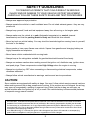
Digital Multimeter
OPERATING
INSTRUCTIONS
®
AC V
DC V
OFF
750
CP7676
4
CYL
200
5
CYL
20
RPM
X10
6
CYL
2
8
CYL
20M
4
CYL
2M
5
CYL
200K
Instrucciones en español,
páginas 37-72
6
CYL
OHMS
20K
8
2K
200
COM
CYL
DWELL
CP7676
V
750V AC
200V DC
Index
Ignition System Testing .............................. 20
- Ignition Coil Testing .............................. 20
- Ignition System Wires .......................... 22
- Hall Effect Sensors/Switches .............. 23
- Magnetic Pick-Up Coils ........................ 24
- Reluctance Sensors ............................. 24
- Ignition Coil Switching Action .............. 25
Safety Precautions ............................. 2
Vehicle Service Information ............... 3
Visual Inspection ................................ 3
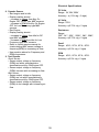
Electrical Specifications ................... 35
Warranty ........................................... 72
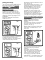
1. Multimeter Basic Functions
Functions and Display Definitions ............ 4
Setting the Range ..................................... 6
Battery Replacement ................................ 7
Measuring AC Voltage .............................. 7
Measuring DC Voltage .............................. 8
Measuring Resistance .............................. 8
Testing for Continuity ................................ 9
Testing Diodes .......................................... 9
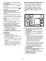
Measuring Engine RPM (TACH) ............ 10
Measuring Dwell ...................................... 11
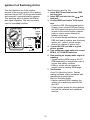
Fuel System Testing ................................... 26
- Testing Mixture Control Solenoid
on Feedback Carburetor ...................... 26
- Measuring Fuel Injector Resistance .... 27
Testing Engine Sensors .............................. 28
- Oxygen (O2) Type Sensors .................. 28
- Temperature Type Sensors .................. 30
- Position Type Sensors
Throttle and EGR Valve Position,
Vane Air Flow ........................................ 31
- Manifold Absolute Pressure (MAP) and
Barometric Pressure (BARO) Sensors .. 32
- Mass Air Flow (MAF) Sensors ............. 34
2. Automotive Testing with the CP7676
General Testing ....................................... 13
- Testing Fuses ....................................... 13
- Testing Switches .................................. 13
- Testing Solenoids and Relays ............. 14
Starting / Charging System Testing ............ 15
- No Load Battery Test ........................... 15
- Cranking Voltage/Battery Load Test .... 16
- Voltage Drops ....................................... 17
- Charging System Voltage Test ............ 18
1
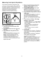
SAFETY GUIDELINES
TO PREVENT ACCIDENTS THAT COULD RESULT IN SERIOUS
INJURY AND/OR DAMAGE TO YOUR VEHICLE OR TEST EQUIPMENT,
CAREFULLY FOLLOW THESE SAFETY RULES AND TEST PROCEDURES
Always wear approved eye protection.
Always operate the vehicle in a well ventilated area. Do not inhale exhaust gases they are very
poisonous!
Always keep yourself, tools and test equipment away from all moving or hot engine parts.
Always make sure the vehicle is in park (Automatic transmission) or neutral (manual
transmission) and that the parking brake is firmly set. Block the drive wheels.
Never lay tools on vehicle battery. You may short the terminals together causing harm to yourself,
the tools or the battery.
Never smoke or have open flames near vehicle. Vapors from gasoline and charging battery are
highly flammable and explosive.
Never leave vehicle unattended while running tests.
Always keep a fire extinguisher suitable for gasoline/electrical/chemical fires handy.
Always use extreme caution when working around the ignition coil, distributor cap, ignition wires,
and spark plugs. These components contain High Voltage when the engine is running.
Always turn ignition key OFF when connecting or disconnecting electrical components, unless
otherwise instructed.
Always follow vehicle manufacturers warnings, cautions and service procedures.
CAUTION:
Some vehicles are equipped with safety air bags. You must follow vehicle service manual cautions
when working around the air bag components or wiring. If the cautions are not followed, the air bag
may open up unexpectedly, resulting in personal injury. Note that the air bag can still open up
several minutes after the ignition key is off (or even if the vehicle battery is disconnected) because
of a special energy reserve module.
All information, illustrations and specifications contained in this manual are based on the latest information
available from industry sources at the time of publication. No warranty (expressed or implied) can be made
for its accuracy or completeness, nor is any responsibility assumed by Actron Manufacturing Co. or anyone
connected with it for loss or damages suffered through reliance on any information contained in this manual
or misuse of accompanying product. A
ctron Manufacturing Co. reserves the right to make changes at any time to this manual or accompanying
product without obligation to notify any person or organization of such changes.
2
Vehicle Service Manual Sources For Service Information
The following is a list of sources to obtain vehicle service information for your specific vehicle.
Contact your local Automotive Dealership Parts Department.
Contact local retail auto parts stores for aftermarket vehicle service information.
Contact your local library. Libraries often allow you to check-out automotive service manuals.
Do a Thorough Visual Inspection
Do a thorough visual and hands-on underhood inspection before starting any diagnostic
procedure! You can find the cause of many problems by just looking, thereby saving yourself a lot
of time.
Has the vehicle been serviced recently? Sometimes things get reconnected in the wrong place,
or not at all.
Dont take shortcuts. Inspect hoses and wiring which may be difficult to see due to location.
Inspect the air cleaner and ductwork for defects.
Check sensors and actuators for damage.
Inspect ignition wires for:
- Damaged terminals.
- Split or cracked spark plug boots
- Splits, cuts or breaks in the ignition wires and insulation.
Inspect all vacuum hoses for:
- Correct routing. Refer to vehicle service manual, or Vehicle Emission Control
Information(VECI) decal located in the engine compartment.
- Pinches and kinks.
- Splits, cuts or breaks.
Inspect wiring for:
- Contact with sharp edges.
- Contact with hot surfaces, such as exhaust manifolds.
- Pinched, burned or chafed insulation.
- Proper routing and connections.
Check electrical connectors for:
- Corrosion on pins.
- Bent or damaged pins.
- Contacts not properly seated in housing.
- Bad wire crimps to terminals.
3
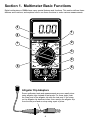
Section 1. Multimeter Basic Functions
Digital multimeters or DMMs have many special features and functions. This section defines these
features and functions, and explains how to use these functions to make various measurements.
9
1
8
®
7
AC V
DC V
OFF
750
CP7676
4
CYL
200
5
CYL
RPM
X10
6
20
CYL
8
2
CYL
CYL
5
2M
CYL
4
6
200K
CYL
8
20K
OHMS
3
4
20M
6
2
2K
CYL
200
COM
DWELL
5
V
750V AC
200V DC
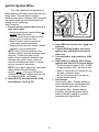
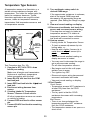
Alligator Clip Adapters
Some multimeter tests and measurements are more easily done
using alligator clips instead of test prods. For these tests, push
the crimp end of the alligator clip onto the test prod. If the crimp
on the alligator clip becomes loose, then remove the alligator clip
from the test prod and re-crimp using a pair of pliers.
4
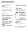
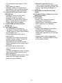
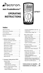
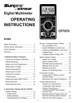
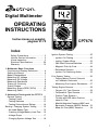
Functions and Display Definitions
(Refer to Digital Multimeter illustration on facing page)
1. ROTARY SWITCH
Switch is rotated to turn multimeter ON/
OFF and select a function.
8. AC VOLTS
This Function is used for measuring AC
(Alternating Current) Voltages in the range
of 0 to 750V.
2. RPM X 10
This Function is used for measuring
engine speed (RPM).
9. DISPLAY
Used to display all measurements and
multimeter information.
3. DWELL
This Function is used for measuring
DWELL on distributor ignition systems,
and solenoids.
Low Battery If LO BAT appears in the
upper left corner of the display, then
replace the internal 9V
battery. (see Battery
Replacement on page 7.)
4. DIODE CHECK
This Function is used to check whether a
diode is good or bad.
Overrange Indication If 1
or -1 appears on the left
side of the display, then the
multimeter is set to a range
that is too small for the
present measurement being
taken. Increase the range
until this disappears. If it
does not disappear after all the ranges for
a particular function have been tried, then
the value being measured is too large for
the multimeter to measure. (see Setting
the Range on page 6.)
5. TEST LEAD JACKS
BLACK Test Lead is always inserted in the
COM test lead jack.
RED Test Lead is always inserted in the
or V
test lead jack.
Always connect TEST LEADS to the
multimeter before connecting them to
the circuit under test!!
6. OHMS
This Function is used for measuring the
resistance of a component in an electrical
circuit in the range of 0.1Ω to 20MΩ. (Ω is
the electrical symbol for Ohms)
Zero Adjustment
The multimeter will automatically zero on the
Volts, Amps, and RPM functions.
7. DC VOLTS
This Function is used for measuring DC
(Direct Current) Voltages in the range of 0
to 200V.
Automatic Polarity Sensing
The multimeter display will show a minus (-)
sign on the DC Volts and DC Amps functions
when test lead hook-up is reversed.
5
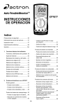
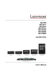
Setting the Range
Now assume we set the multimeter to the 2V
range. (See Fig. 2)
The multimeter display now shows a 1 and
nothing else. This means the multimeter is
being overranged or in other words the
value being measured is larger than the
current range. The range should be
increased until a value is shown on the
display. If you are in the highest range and
the multimeter is still showing that it is
overranging, then the value being measured
is too large for the multimeter to measure.
Two of the most commonly asked questions
about digital multimeters are What does
Range mean? and How do I know what
Range the multimeter should be set to?
What Does Range mean?
Range refers to the largest value the
multimeter can measure with the rotary
switch in that position. If the multimeter is
set to the 20V DC range, then the highest
voltage the multimeter can measure is 20V
in that range.
EXAMPLE: Measuring Vehicle Battery
Voltage (See Fig. 1)
How do I know what Range the multimeter
should be set to?
The multimeter should be set in the lowest
possible range without overranging.
EXAMPLE: Measuring an unknown
resistance
Lets assume the multimeter is connected to
an engine coolant sensor with unknown
resistance. (See Fig. 3)
Start by setting the multimeter to the largest
OHM range. The display reads 0.0Ω or a
short circuit.
Fig. 1
®
CP7676
DC V
200
AC V OFF
4
750
CYL 5
RPM
X10
6
CYL
20
CYL
8
2
CYL
4
20M
CYL
5
2M
CYL
6
200K
OHMS
Red
CYL
8
20K
CYL
2K 200
Black
Fig. 3
DWELL
COM
V
750V AC
200V DC
®
CP7676
DC V
Lets assume the multimeter is connected to
the battery and set to the 20V range.
The display reads 12.56. This means there is
12.56V across the battery terminals.
200
20
CYL
8
4
CYL
5
2M
CYL
6
OHMS
CYL
8
20K
CYL
2K 200
COM
Red
CYL
2K 200
DWELL
V
Red
Black
This sensor cant be shorted so reduce the
range setting until you get a value of
resistance.
At the 200KΩ range the multimeter
measured a value of 4.0. This means there
is 4KΩ of resistance across the engine
coolant sensor terminals. (See Fig. 4)
If we change the multimeter to the 20KΩ
range (See Fig. 5) the display shows a value
of 3.87KΩ. The actual value of resistance is
CYL
200K
8
20K
750V AC
200V DC
CYL
20M
CYL
6
CYL
COM
CP7676
200
4
CYL
5
2M
RPM
X10
6
20
8
CYL
200K
®
2
CYL
20M
Fig. 2
AC V OFF
4
750
CYL 5
RPM
X10
6
CYL
2
OHMS
DC V
AC V OFF
4
750
CYL 5
Black
DWELL
V
750V AC
200V DC
6
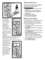
Battery Replacement
Fig. 4
Important: A 9 Volt battery must be installed
before using the digital multimeter. (See
procedure below for installation.)
Battery Replacement
1. Turn multimeter rotary switch to OFF
position.
2. Remove test leads from multimeter.
3. Remove three screws from back of
multimeter.
4. Remove back cover.
5. Install a new 9 Volt battery.
6. Re-assemble multimeter.
®
CP7676
DC V
200
AC V OFF
4
750
CYL 5
RPM
X10
6
CYL
20
CYL
8
2
CYL
4
20M
CYL
5
2M
CYL
6
200K
OHMS
CYL
8
20K
CYL
2K 200
COM
DWELL
V
Red
Black
750V AC
200V DC
3.87KΩ and not
4KΩ that was
Fig. 5
measured in the
200KΩ range. This
is very important
because if the
manufacturer
AC V OFF
RPM
4
DC V
750
specifications say
5 X10
200
6
20
that the sensor
8
2
should read 3.84
20M
5
2M
3.9KΩ at 70°F then
6
200K
8
on the 200KΩ range
20K
OHMS
2K 200
DWELL
the sensor would be
defective, but at the
COM
V
20KΩ range it would
test good.
Now set the
multimeter to the 2KΩ range. (See Fig. 6) The
display will indicate an overrange condition
because 3.87KΩ is larger than 2KΩ.
This example shows that by decreasing the
range you increase
Fig. 6
the accuracy of
your measurement.
When you change
the range, you
change the location
of the decimal
AC V OFF
RPM
4
DC V
750
5 X10
200
point. This changes
6
20
8
the accuracy of the
2
4
20M
measurement by
5
2M
either increasing or
6
200K
8
20K
decreasing the
OHMS
2K 200
DWELL
number of digits
after the decimal
COM
V
point.
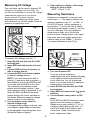
Measuring AC Voltage
This multimeter can be used to measure AC
voltages in the range of 0 to 750V. You can
use this multimeter for trouble-shooting
household electrical wiring and appliances.
To measure AC Voltages:
1. Insert BLACK test lead into the COM
test lead jack.
2. Insert RED test lead into the V
test
lead jack.
3. Connect RED test lead to either side of
AC voltage source.
4. Connect BLACK test lead to remaining
side of AC voltage source.
NOTE: Since AC voltages alternate
between a positive and negative value,
test lead hook-up polarity is not important.
5. Turn multimeter rotary switch to 750
AC V voltage range.
6. View reading on display.
®
CP7676
CYL
CYL
CYL
CYL
CYL
CYL
CYL
CYL
750V AC
200V DC
®
CP7676
CYL
CYL
CYL
CYL
CYL
CYL
CYL
CYL
750V AC
200V DC
7
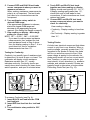
Measuring DC Voltage
6. View reading on display - Note range
setting for correct units.
NOTE: 200mV = 0.2V
This multimeter can be used to measure DC
voltages in the range from 0 to 200V. You
can use this multimeter to do any DC voltage
measurement called out in the vehicle
service manual. The most common
applications are measuring voltage drops,
and checking if the correct voltage arrived at
a sensor or a particular circuit.
Measuring Resistance
Resistance is measured in electrical units
called ohms (Ω). The digital multimeter can
measure resistance from 0.1Ω to 20MΩ or
(20,000,000 ohms). Infinite resistance is
shown with a 1 on the left side of display
(See Setting the Range on page 6). You can
use this multimeter to do any resistance
measurement called out in the vehicle
service manual. Testing ignition coils, spark
plug wires, and some engine sensors are
common uses for the OHMS (Ω) function.
To measure Resistance (see Fig. 8):
Fig. 7
®
CP7676
DC V
200
AC V OFF
4
750
CYL 5
RPM
X10
6
CYL
20
CYL
8
2
CYL
4
20M
CYL
5
2M
CYL
6
200K
OHMS
CYL
8
20K
CYL
2K 200
COM
DWELL
Red
Black
Fig. 8
V
750V AC
200V DC
4
20M
CYL
5
2M
CYL
To measure DC Voltages (see Fig. 7):
1. Insert BLACK test lead into the COM
test lead jack.
2. Insert RED test lead into the test lead
jack.
3. Connect RED test lead to positive (+)
side of voltage source.
4. Connect BLACK test lead to negative
(-) side of voltage source.
NOTE: If you dont know which side is
positive (+) and which side is negative (-),
then arbitrarily connect the RED test lead
to one side and the BLACK to the other.
The multimeter automatically senses
polarity and will display a minus (-) sign
when negative polarity is measured. If you
switch the RED and BLACK test leads,
positive polarity will now be indicated on
the display. Measuring negative voltages
causes no harm to the multimeter.
5. Turn multimeter rotary switch to
desired voltage range.
If the approximate voltage is unknown, start
at the largest voltage range and decrease
to the appropriate range as required. (See
Setting the Range on page 6)
OHMS
Unknown
Resistance
6
200K
CYL
8
20K
CYL
2K 200
COM
DWELL
V
750V AC
200V DC
Red
Black
1. Turn circuit power OFF.
To get an accurate resistance
measurement and avoid possible damage
to the digital multimeter and electrical
circuit under test, turn off all electrical
power in the circuit where the resistance
measurement is being taken.
2. Insert BLACK test lead into the COM
test lead jack.
3. Insert RED test lead into the V
test
lead jack.
4. Turn multimeter rotary switch to 200Ω
range.
Touch RED and BLACK multimeter leads
together and view reading on display.
Display should read typically 0.2Ω to 1.5Ω.
If display reading was greater than 1.5Ω,
check both ends of test leads for bad
connections. If bad connections are
found, replace test leads.
8
4. Touch RED and BLACK test leads
together and view reading on display.
Display should read typically 0.2Ω to 1.5Ω.
If display reading was greater than 1.5Ω,
check both ends of test leads for bad
connections. If bad connections are found,
replace test leads.
5. Connect RED and BLACK test leads
across component where you want to
check for continuity.
5. Connect RED and BLACK test leads
across component where you want to
measure resistance.
When making resistance measurements,
polarity is not important. The test leads
just have to be connected across the
component.
6. Turn multimeter rotary switch to
desired OHM range.
If the approximate resistance is unknown,
start at the largest OHM range and
decrease to the appropriate range as
required. (See Setting the Range on page 6)
7. View reading on display - Note range
setting for correct units.
NOTE: 2KΩ = 2,000Ω; 2MΩ = 2,000,000Ω
If you want to make precise resistance
measurements, then subtract the test
lead resistance found in Step 4 above
from the display reading in Step 7. It is a
good idea to do this for resistance
measurements less than 10Ω.
View reading on display:
Continuity - Display reading is less than
10Ω.
No Continuity - Display reading is greater
than 10Ω.
Testing Diodes
A diode is an electrical component that allows
current to only flow in one direction. When a
positive voltage, generally greater than 0.7V,
is applied to the anode of a diode, the diode
will turn on and allow current to flow. If this
same voltage is applied to the cathode, the
diode would remain off and no current would
flow. Therefore, in order to test a diode, you
must check it in both directions (i.e. anode-tocathode, and cathode-to-anode). Diodes are
typically found in alternators on automobiles.
Performing Diode Test (see Fig. 10):
Testing for Continuity
Continuity is a specific type of resistance test
to determine if a circuit is open or closed. The
multimeter will display circuit resistance.
Resistance smaller than 10Ω usually
indicates continuity. Continuity checks are
usually done when checking for blown fuses,
switch operation, and open or shorted wires.
Fig. 10
Fig. 9
4
20M
5
2M
6
CYL
2K 200
DWELL
OHMS
Red
COM
5
CYL
6
200K
CYL
8
20K
CYL
8
20K
CYL
2K 200
DWELL
Red
Black
V
COM
750V AC
200V DC
V
750V AC
200V DC
To measure Continuity (see Fig. 9):
1. Insert BLACK test lead into the COM
test lead jack.
2. Insert RED test lead into the test lead
jack.
3. Turn multimeter rotary switch to 200Ω
range.
9
Cathode
CYL
2M
CYL
200K
OHMS
Anode
4
20M
CYL
Black
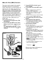
Measuring Engine RPM (TACH)
1. Insert BLACK test lead into the COM
test lead jack.
2. Insert RED test lead into the V
test
lead jack.
The CP7676 has a RPM X 10 function for
measuring engine speed or RPM. When
using the RPM X 10 function, you must
multiply the display reading by 10 to get
actual RPM. If display reads 200, then the
actual engine RPM is 10 times 200 or 2000
RPM.
3. Turn multimeter rotary switch to
function.
4. Touch RED and BLACK test leads
together to test continuity.
Display reading should be approximately
zero volts.
If display reads greater than 0.5V, then
check both test leads for bad connections.
If bad connections are found, replace test
leads.
5. Disconnect one end of diode from
circuit.
Diode must be totally isolated from circuit
in order to test its functionality.
6. Connect RED and BLACK test leads
across diode and view display.
Display will show one of three things:
A typical voltage drop of around 0.7V.
A voltage drop of 0 volts.
A 1 will appear indicating the
multimeter is overranged.
7. Switch RED and BLACK test leads and
repeat Step 6.
8. Test Results
If the display showed:
A voltage drop of 0 volts in both
directions, then the diode is shorted and
needs to be replaced.
A 1 appears in both directions, then the
diode is an open circuit and needs to be
replaced.
The diode is good if the display reads
around 0.7V in one direction and a 1
appears in the other direction indicating
the multimeter is overranged.
DC V
200
OFF
AC VOFF
4
750
CYL 5
RPM
X10
6
CYL
20
8
2
Typical
Ignition
Coil
CYL
4
20M
CYL
5
2M
CYL
6
200K
OHMS
Fig. 11
CYL
Red
CYL
8
20K
CYL
2K 200
COM
DWELL
V
750V AC
200V DC
Black
Ground
To Measure Engine RPM (TACH) (see Fig. 11):
1. Insert BLACK test lead into the COM
test lead jack.
2. Insert RED test lead into the
test
lead jack.
3. Connect RED test lead to RPM (TACH)
signal wire.
If vehicle is DIS (Distributorless Ignition
System), then connect RED test lead to
the RPM (TACH) signal wire going from
the DIS module to the vehicle engine
computer. (refer to vehicle service
manual for location of this wire)
For all vehicles with distributors, connect
RED test lead to negative side of primary
ignition coil. (refer to vehicle service
manual for location of ignition coil)
4. Connect BLACK test lead to a good
vehicle ground.
5. Turn multimeter rotary switch to correct
RPM X 10 CYLINDER selection.
6. Measure engine RPM while engine is
cranking or running.
7. View reading on display.
10
Measuring Dwell
Dwell measuring was extremely important on
breaker point ignition systems of the past. It
referred to the length of time, in degrees, that
the breaker points remained closed, while the
camshaft was rotating. Todays vehicles use
electronic ignition and dwell is no longer
adjustable. Another application for dwell
is in testing the mixture control solenoid on
GM feedback carburetors.
To Measure Dwell (see Fig. 12):
4
20M
CYL
6
200K
OHMS
Fig. 12
CYL
5
2M
CYL
Red
Typical
Ignition
Coil
8
20K
CYL
2K 200
COM
DWELL
V
750V AC
200V DC
Black
Ground
1. Insert BLACK test lead into the COM
test lead jack.
2. Insert RED test lead into the test lead
jack.
3. Connect RED test lead to DWELL signal
wire.
If measuring DWELL on breaker point
ignition systems, connect RED test lead
to negative side of primary ignition coil.
(refer to vehicle service manual for
location of ignition coil)
If measuring DWELL on GM mixture
control solenoids, connect RED test lead
to ground side or computer driven side
of solenoid. (refer to vehicle service
manual for solenoid location)
If measuring DWELL on any arbitrary
ON/OFF device, connect RED test lead
to side of device that is being switched
ON/OFF.
4. Connect BLACK test lead to a good
vehicle ground.
5. Turn multimeter rotary switch to correct
DWELL CYLINDER position.
6. View reading on display.
11
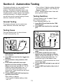
Section 2. Automotive Testing
The digital multimeter is a very useful tool for
trouble-shooting automotive electrical
systems. This section describes how to use
the digital multimeter to test the starting and
charging system, ignition system, fuel system,
and engine sensors. The digital multimeter
can also be used for general testing of fuses,
switches, solenoids, and relays.
Fuse is blown if display reading indicates
an overrange condition. (see Setting the
Range on page 6)
NOTE: Always replace blown fuses with
same type and rating.
Testing Switches
This test checks to see if a switch Opens
and Closes properly.
To test Switches (see Fig. 14):
1. Insert BLACK test lead into the COM
test lead jack.
2. Insert RED test lead into the test lead
jack.
General Testing
The digital multimeter can be used to test
fuses, switches, solenoids, and relays.
Testing Fuses
Fig. 14
This test checks to see if a fuse is blown.
To test Fuses (see Fig. 13):
DC V
200
AC V OFF
4
750
CYL 5
20
8
CYL
4
20M
CYL
6
200K
CYL
OHMS
5
2M
CYL
5
2M
Fuse
4
20M
CYL
CYL
8
20K
CYL
2K 200
DWELL
6
200K
OHMS
CYL
2
Fig. 13
Typical
"Push"
Button
Switch
RPM
X10
6
CYL
Red
Black
CYL
8
20K
CYL
2K 200
COM
DWELL
COM
V
V
750V AC
200V DC
Red
Black
750V AC
200V DC
1. Insert BLACK test lead into the COM
test lead jack.
2. Insert RED test lead into the V
test
lead jack.
3. Turn multimeter rotary switch to 200Ω
range.
4. Touch RED and BLACK test leads
together and view reading on display.
Display should read typically 0.2Ω to 1.5Ω.
If display reading was greater than 1.5Ω,
check both ends of test leads for bad
connections. If bad connections are found,
replace test leads.
5. Connect RED and BLACK test leads to
opposite ends of fuse.
View reading on display:
Fuse is good if display reading is less
than 10Ω.
3. Turn multimeter rotary switch to 200Ω
range.
4. Touch RED and BLACK test leads
together and view reading on display.
Display should read typically 0.2Ω to 1.5Ω.
If display reading was greater than 1.5Ω,
check both ends of test leads for bad
connections. If bad connections are found,
replace test leads.
5. Connect BLACK test lead to one side of
switch.
6. Connect RED test lead to other side of
switch.
13
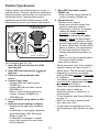
3. Turn multimeter rotary switch to 200Ω
range.
Most solenoids and relay coil resistances
are less than 200Ω. If meter overranges,
turn multimeter rotary switch to next
higher range. (see Setting the Range on
page 6)
4. Touch RED and BLACK test leads
together and view display.
Display should read typically 0.2Ω to 1.5Ω.
If display reading was greater than 1.5Ω,
check both ends of test leads for bad
connections. If bad connections are
found, replace test leads.
5. Connect BLACK test lead to one side
of coil.
6. Connect RED test lead to other side of
coil.
7. View reading on display.
Typical solenoid / relay coil resistances
are 200Ω or less.
Refer to vehicle service manual for your
vehicles resistance range.
8. Test Results
Good Solenoid / Relay Coil: Display in
Step 7 is within manufacturers
specification.
Bad Solenoid / Relay Coil:
Display in Step 7 is not within
manufacturers specifications.
Display reads overrange on every ohms
range indicating an open circuit.
NOTE: Some relays and solenoids have
a diode placed across the coil. To test this
diode see Testing Diodes on page 9.
View reading on display:
Switch is closed if display reading is less
than 10Ω.
Switch is open if display reading
indicates an overrange condition. (see
Setting the Range on page 6)
7. Operate switch.
View reading on display:
Switch is closed if display reading is less
than 10Ω.
Switch is open if display reading indicates
an overrange condition. (see Setting the
Range on page 6)
8. Repeat Step 7 to verify switch
operation.
Good Switch: Display reading alternates
from a 10Ω or less value to an overrange
condition as you operate switch.
Bad Switch: Display reading remains
unchanged as you operate switch.
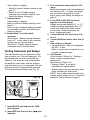
Testing Solenoids and Relays
This test checks to see if a solenoid or relay
have a broken coil. If the coil tests good, it is
still possible that the relay or solenoid are
defective. The relay can have contacts that
are welded or worn down, and the solenoid
may stick when the coil is energized. This test
does not check for those potential problems.
To test Solenoids and Relays (see Fig. 15):
Fig. 15
4
20M
CYL
5
2M
CYL
6
200K
OHMS
Relay or Solenoid
CYL
8
20K
CYL
2K 200
DWELL
Red
COM
Black
V
750V AC
200V DC
1. Insert BLACK test lead into the COM
test lead jack.
2. Insert RED test lead into the V
test
lead jack.
14
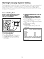
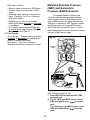
Starting/Charging System Testing
The starting system turns over the engine. It consists of the battery, starter motor, starter solenoid
and/or relay, and associated wiring and connections. The charging system keeps the battery
charged when the engine is running. This system consists of the alternator, voltage regulator,
battery, and associated wiring and connections. The digital multimeter is a useful tool for checking
the operation of these systems.
No Load Battery Test
4. Insert RED test lead into the V
test
lead jack.
5. Disconnect positive (+) battery cable.
6. Connect RED test lead to positive (+)
terminal of battery.
7. Connect BLACK test lead to negative
(-) terminal of battery.
8. Turn multimeter rotary switch to 20V DC
range.
9. View reading on display.
10. Test Results.
Compare display reading in Step 9 with
chart below.
Before you do any starting/charging system
checks, you must first test the battery to
make sure it is fully charged.
Fig. 16
DC V
200
AC V OFF
4
750
CYL 5
RPM
X10
6
CYL
20
CYL
8
2
CYL
4
20M
CYL
5
2M
CYL
6
200K
OHMS
CYL
8
20K
CYL
2K 200
COM
DWELL
Red
Black
V
Voltage
750V AC
200V DC
Percent Battery is Charged
12.60V
or greater
100%
12.45V
75%
12.30V
50%
12.15V
25%
If battery is not 100% charged, then charge
it before doing any more starting/charging
system tests.
Test Procedure (see Fig. 16):
1. Turn Ignition Key OFF.
2. Turn ON headlights for 10 seconds to
dissipate battery surface charge.
3. Insert BLACK test lead into the COM
test lead jack.
15
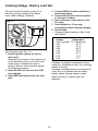
Cranking Voltage - Battery Load Test
4. Connect RED test lead to positive (+)
terminal of battery.
5. Connect BLACK test lead to negative
(-) terminal of battery.
6. Turn multimeter rotary switch to 20V
DC range.
7. Crank engine for 15 seconds
continuously while observing display.
8. Test Results.
Compare display reading in Step 7 with
chart below.
This test checks the battery to see if it is
delivering enough voltage to the starter
motor under cranking conditions.
Fig. 17
DC V
200
AC V OFF
4
750
CYL 5
RPM
X10
6
CYL
20
CYL
8
2
CYL
4
20M
CYL
5
2M
CYL
6
200K
OHMS
CYL
8
20K
CYL
2K 200
COM
DWELL
Red
Black
Voltage
Temperature
9.6V or greater 70 °F and Above
9.5V
60 °F
9.4V
50 °F
9.3V
40 °F
9.1V
30 °F
8.9V
20 °F
8.7V
10 °F
8.5V
0 °F
V
750V AC
200V DC
Test Procedure (see Fig. 17):
1. Disable ignition system so vehicle
wont start.
Disconnect the primary of the ignition coil
or the distributor pick-up coil or the cam/
crank sensor to disable the ignition
system. Refer to vehicle service manual
for disabling procedure.
2. Insert BLACK test lead into the COM
test lead jack.
3. Insert RED test lead into the test lead
jack.
If voltage on display corresponds to above
voltage vs. temperature chart, then cranking
system is normal.
If voltage on display does not correspond to
chart, then it is possible that the battery,
battery cables, starting system cables,
starter solenoid, or starter motor are
defective.
16
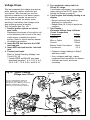
Voltage Drops
5. Turn multimeter rotary switch to
200mV DC range.
If multimeter overranges, turn multimeter
rotary switch to the 2V DC range. (See
Setting the Range on page 6)
6. Crank engine until steady reading is on
display.
Record results at each point as
displayed on multimeter.
Repeat Step 4 & 5 until all points are
checked.
7. Test Results
Estimated Voltage Drop of Starter
Circuit Components
Component
Voltage
Switches
300mV
Wire or Cable
200mV
Ground
100mV
Battery Cable Connectors
50mV
Connections
0.0 V
This test measures the voltage drop across
wires, switches, cables, solenoids, and
connections. With this test you can find
excessive resistance in the starter system.
This resistance restricts the amount of
current that reaches the starter motor
resulting in low battery load voltage and a
slow cranking engine at starting.
Test Procedure (see Fig. 18):
1. Disable ignition system so vehicle
wont start.
Disconnect the primary of the ignition coil
or the distributor pick-up coil or the cam/
crank sensor to disable the ignition
system. Refer to vehicle service manual
for disabling procedure.
2. Insert BLACK test lead into the COM
test lead jack.
3. Insert RED test lead into the test lead
jack.
4. Connect test leads.
Refer to Typical Cranking Voltage Loss
Circuit (Fig. 18).
Connect RED and BLACK test leads
alternately between 1 & 2, 2 & 3, 4 & 5,
5 & 6, 6 & 7, 7 & 8, 8 & 9, and 8 & 10.
Compare voltage readings in Step 6
with above chart.
If any voltages read high, inspect
component and connection for defects.
If defects are found, service as
necessary.
Fig. 18 Typical Cranking
Voltage Loss Circuit
Solenoid
9
8
6
8
6
This is a representative sample of
one type of cranking circuit. Your
vehicle may use a different circuit with
different components or locations.
Consult your vehicle service manual.
7
9
7
Red
5
Black
5
4
3
4
2
Starter
10
3
2
1
17
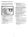
Charging System Voltage Test
This test checks the charging system to see
if it charges the battery and provides power
to the rest of the vehicles electrical systems
(lights, fan, radio etc).
7. Turn off all accessories and view
reading on display.
Charging system is normal if display
reads 13.2 to 15.2 volts.
If display voltage is not between 13.2 to
15.2 volts, then proceed to Step 13.
8. Open throttle and Hold engine speed
(RPM) between 1800 and 2800 RPMs.
Hold this speed through Step 11 - Have
an assistance help hold speed.
9. View reading on display.
Voltage reading should not change from
Step 7 by more than 0.5V.
10.Load the electrical system by turning
on the lights, windshield wipers, and
setting the blower fan on high.
11. View reading on display.
Voltage should not drop down below
about 13.0V.
12.Shut off all accessories, return engine
to curb idle and shut off.
13. Test Results.
If voltage readings in Steps 7, 9, and 11
were as expected, then charging system
is normal.
If any voltage readings in Steps 7, 9, and
11 were different then shown here or in
vehicle service manual, then check for a
loose alternator belt, defective regulator
or alternator, poor connections, or open
alternator field current.
Refer to vehicle service manual for
further diagnosis.
Fig. 19
DC V
200
AC V OFF
4
750
CYL 5
RPM
X10
6
CYL
20
CYL
8
2
CYL
4
20M
CYL
5
2M
CYL
6
200K
OHMS
CYL
8
20K
CYL
2K 200
COM
DWELL
Red
Black
V
750V AC
200V DC
Test Procedure (see Fig. 19):
1. Insert BLACK test lead into the COM
test lead jack.
2. Insert RED test lead into the V
test
lead jack.
3. Connect RED test lead to positive (+)
terminal of battery.
4. Connect BLACK test lead to negative
(-) terminal of battery.
5. Turn multimeter rotary switch to 20V
DC range.
6. Start engine - Let idle.
18
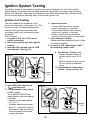
Ignition System Testing
The ignition system is responsible for providing the spark that ignites the fuel in the cylinder.
Ignition system components that the digital multimeter can test are the primary and secondary
ignition coil resistance, spark plug wire resistance, hall effect switches/sensors, reluctance pickup coil sensors, and the switching action of the primary ignition coil.
Ignition Coil Testing
This test measures the resistance of the
primary and secondary of an ignition coil. This
test can be used for distributorless ignition
systems (DIS) provided the primary and
secondary ignition coil terminals are easily
accessible.
Test Procedure:
1. If engine is HOT let it COOL down
before proceeding.
2. Disconnect ignition coil from ignition
system.
3. Insert BLACK test lead into the COM
test lead jack. (See Fig. 20.)
Fig. 20
4
750
CYL
200
RPM
X10
6
5
CYL
20
9. Test Results - Primary Coil
Typical resistance range of
primary ignition coils is 0.3 2.0Ω.
Refer to vehicle service manual
for your vehicle's resistance
range.
10. Turn multimeter rotary switch
to 200KΩ range (see Fig. 21).
Secondary
Coil
CYL
8
2
CYL
4
20M
CYL
5
2M
Red
Black
CYL
6
200K
OHMS
6. Connect test leads.
Connect RED test lead to primary
ignition coil positive (+) terminal.
Connect BLACK test lead to primary
ignition coil negative (-) terminal.
Refer to vehicle service manual for
location of primary ignition coil terminals.
7. View reading on display.
Subtract test lead resistance found in Step
5 from above reading.
8. If vehicle is DIS, repeat Steps 6 and 7
for remaining ignition coils.
CYL
8
20K
CYL
2K 200
COM
DWELL
V
Primary
Coil
750V AC
200V DC
Typical Cylindrical
Ignition Coil
4. Insert RED test lead into the
test lead jack.
V
5. Turn multimeter rotary switch
to 200Ω range.
Touch RED and BLACK test
leads together and view reading
on display.
Display should read typically
0.2Ω to 1.5Ω.
If display reading was greater
than 1.5Ω, check both ends of
test leads for bad connections.
If bad connections are found,
replace test leads.
Fig. 21
4
750
CYL
200
RPM
X10
6
5
CYL
20
Secondary
Coil
CYL
8
2
CYL
4
20M
CYL
Red
Black
5
2M
CYL
6
200K
OHMS
CYL
8
20K
CYL
2K 200
COM
DWELL
Primary
Coil
V
750V AC
200V DC
Typical Cylindrical
Ignition Coil
20
11. Move RED test lead to secondary
ignition coil terminal.
Refer to vehicle service manual for
location of secondary ignition coil
terminal.
Verify BLACK test lead is connected to
primary ignition coil negative (-) terminal.
12. View reading on display.
13. If vehicle is DIS, repeat Steps 11 and 12
for remaining ignition coils.
14. Test Results - Secondary Coil
Typical resistance range of secondary
ignition coils is 6.0 - 30.0KΩ.
Refer to vehicle service manual for your
vehicles resistance range.
15. Repeat test procedure for a HOT
ignition coil.
NOTE: It is a good idea to test ignition
coils when they are both hot and cold,
because the resistance of the coil could
change with temperature. This will also
help in diagnosing intermittent ignition
system problems.
16. Test Results - Overall
Good Ignition Coil: Resistance readings in
Steps 9, 14 and 15 were within
manufacturers specification.
Bad Ignition Coil: Resistance readings in
Steps 9, 14 and 15 are not within
manufacturers specification.
21
Ignition System Wires
This test measures the resistance of
spark plug and coil tower wires while they are
being flexed. This test can be used for
distributorless ignition systems (DIS) provided
the system does not mount the ignition coil
directly on the spark plug.
Test Procedure:
1. Remove ignition system wires one at a
time from engine.
Always grasp ignition system wires on
the boot when removing.
Twist the boots about a half turn while
pulling gently to remove them.
Refer to vehicle service manual for
ignition wire removal procedure.
Inspect ignition wires for cracks, chaffed
insulation, and corroded ends.
NOTE: Some Chrysler products use a
positive-locking terminal electrode spark
plug wire. These wires can only be
removed from inside the distributor cap.
Damage may result if other means of
removal are attempted. Refer to vehicle
service manual for procedure.
NOTE: Some spark plug wires have sheet
metal jackets with the following
symbol:
. This type of plug wire
contains an air gap resistor and can only
be checked with an oscilloscope.
2. Insert BLACK test lead into the COM
test lead jack. (See Fig. 22.)
Fig. 22
4
750
CYL
200
RPM
X10
6
5
CYL
20
8
2
CYL
4
20M
CYL
5
2M
Red
CYL
6
200K
OHMS
Black
CYL
CYL
8
20K
CYL
2K 200
COM
DWELL
V
750V AC
200V DC
Spark Plug Wire
3. Insert RED test lead into the V
test
lead jack.
4. Connect RED test lead to one end of
ignition wire and BLACK test lead to
other end.
5. Turn multimeter rotary switch to 200KΩ
range.
6. View reading on display while flexing
ignition wire and boot in several places.
Typical resistance range is 3KΩ to 50KΩ
or approximately 10KΩ per foot of wire.
Refer to vehicle service manual for your
vehicles resistance range.
As you flex ignition wire, the display
should remain steady.
7. Test Results
Good Ignition Wire: Display reading is
within manufacturers specification and
remains steady while wire is flexed.
Bad Ignition Wire: Display reading
erratically changes as ignition wire is
flexed or display reading is not within
manufacturers specification.
22
Hall Effect Sensors/Switches
6. Connect BLACK test lead to 9V battery
negative (-) pin.
7. Turn multimeter rotary switch to 200Ω
range.
Multimeter display should read a small
ohm value.
8. Slide a flat blade of iron or magnetic
steel between sensor and magnet. (Use
a scrap of sheet metal, knife blade, steel
ruler, etc.)
Multimeter display should indicate an
overrange condition.
Remove steel blade and multimeter
should again display a small ohm value.
It is O.K. if display changes erratically
after steel blade is removed.
Repeat several times to verify results.
9. Test Results.
Hall Effect sensors are used whenever the
vehicle computer needs to know speed and
position of a rotating object. Hall Effect
sensors are commonly used in ignition
systems to determine camshaft and
crankshaft position so the vehicle computer
knows the optimum time to fire the ignition
coil(s) and turn on the fuel injectors. This test
checks for proper operation of the Hall Effect
sensor / switch.
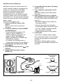
Test Procedure (see Fig. 23):
1. Remove Hall Effect Sensor from
vehicle.
Refer to vehicle service manual for
procedure.
2. Connect 9V battery to sensor POWER
and GROUND pins.
Connect positive(+) terminal of 9V
battery to sensor POWER pin.
Connect negative(-) terminal of 9V
battery to sensor GROUND pin.
Refer to illustrations for POWER and
GROUND pin locations.
For sensors not illustrated refer to
vehicle service manual for pin locations.
3. Insert BLACK test lead into the COM
test lead jack.
4. Insert RED test lead into the V
test
lead jack.
5. Connect RED test lead to sensor
SIGNAL pin.
Good Sensor: Display reading toggles
from a small ohmic value to an overrange
condition as steel blade is inserted and
removed.
Bad Sensor: Display reading remains
unchanged as steel blade is inserted and
removed.
Fig. 23
Chrysler Distributor
Hall Effect
Black
4
750
CYL
200
20
9V
CYL
8
2
CYL
20M
4
Jumper
Wires
GROUND
CYL
5
2M
Iron or
Steel Blade
CYL
6
200K
OHMS
POWER
RPM
X10
6
5
CYL
POWER
CYL
8
20K
CYL
2K 200
Sensor
DWELL
SIGNAL
Ford Distributor
Hall Effect
GROUND
COM
Magnet
V
SIGNAL
750V AC
200V DC
Typical Hall
Effect Sensor
Red
23
SIGNAL
GROUND
POWER
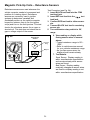
Magnetic Pick-Up Coils Reluctance Sensors
Reluctance sensors are used whenever the
vehicle computer needs to know speed and
position of a rotating object. Reluctance
sensors are commonly used in ignition
systems to determine camshaft and
crankshaft position so the vehicle computer
knows the optimum time to fire the ignition
coil(s) and turn on the fuel injectors. This test
checks the reluctance sensor for an open or
shorted coil. This test does not check the air
gap or voltage output of the sensor.
Fig. 24
Reluctance
Sensor
4
750
CYL
200
RPM
X10
6
5
CYL
20
Reluctor
Ring
CYL
8
2
CYL
4
20M
CYL
5
2M
Magnet
CYL
6
200K
OHMS
Test Procedure (see Fig. 24):
1. Insert BLACK test lead into the COM
test lead jack.
2. Insert RED test lead into the V
test
lead jack.
3. Connect RED test lead to either sensor
pin.
4. Connect BLACK test lead to remaining
sensor pin.
5. Turn multimeter rotary switch to 2KΩ
range.
CYL
8
20K
CYL
2K 200
COM
DWELL
V
750V AC
200V DC
Red
Black
24
6. View reading on display while
flexing sensor wires in several
places.
Typical resistance range is 150 1000Ω.
Refer to vehicle service manual
for your vehicles resistance range.
As you flex sensor wires, the
display should remain steady.
7. Test Results
Good Sensor: Display reading is
within manufacturers specification
and remains steady while sensor
wires are flexed.
Bad Sensor: Display reading
erratically changes as sensor wires
are flexed or display reading is not
within manufacturers specification.
Ignition Coil Switching Action
Test Procedure (see Fig. 25):
1. Insert BLACK test lead into the COM
test lead jack.
2. Insert RED test lead into the
test
lead jack.
3. Connect RED test lead to TACH signal
wire.
If vehicle is DIS (Distributorless Ignition
System), then connect RED test lead to
the TACH signal wire going from the DIS
module to the vehicle engine computer.
(refer to vehicle service manual for
location of this wire)
For all vehicles with distributors, connect
RED test lead to negative side of primary
ignition coil. (refer to vehicle service
manual for location of ignition coil)
4. Connect BLACK test lead to a good
vehicle ground.
5. Turn multimeter rotary switch to correct
RPM X 10 CYLINDER selection.
6. View reading on display while engine is
cranking.
Typical cranking RPM range is 50-275
RPM depending on temperature, size of
engine, and battery condition.
Refer to vehicle service manual for
specific vehicle cranking RPM range.
7. Test Results.
Good Coil Switching Action: Display
reading indicated a value consistent with
manufacturers specifications.
Bad Coil Switching Action:
Display read zero RPM, meaning the
ignition coil is not being switched ON
and OFF.
Check ignition system for wiring defects,
and test the camshaft and crankshaft
sensors.
This test checks to see if the negative
terminal of the primary ignition coil is getting
switched ON and OFF via the ignition module
and camshaft / crankshaft position sensors.
This switching action is where the RPM or
tach signal originates. This test is primarily
used for a no start condition.
DC V
200
AC V OFF
4
750
CYL 5
Typical
Ignition
Coil
CYL
8
2
CYL
20M
4
CYL
5
2M
CYL
6
200K
OHMS
Fig. 25
RPM
X10
6
CYL
20
CYL
8
20K
CYL
2K 200
COM
DWELL
V
750V AC
200V DC
Red
Black
Ground
25
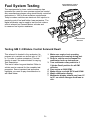
Fuel System Testing
Typical Mixture Control
Solenoid Connection
The requirements for lower vehicle emissions has
increased the need for more precise engine fuel control.
Auto manufacturers began using electronically controlled
carburetors in 1980 to meet emission requirements.
Todays modern vehicles use electronic fuel injection to
precisely control fuel and further lower emissions. The
digital multimeter can be used to test the fuel mixture
control solenoid on General Motors vehicles and
to measure fuel injector resistance.
Mixture Control
Solenoid
Testing GM C-3 Mixture Control Solenoid Dwell
This solenoid is located in the carburetor. Its
purpose is to maintain an air/fuel ratio of 14.7
to 1 in order to reduce emissions. This test
checks to see if the solenoid dwell is varying.
Test Description:
This test is rather long and detailed. Refer to
vehicle service manual for the complete test
procedure. Some important test procedure
highlights you need to pay close attention to
are listed below.
1. Make sure engine is at operating
temperature and running during test.
2. Refer to vehicle service manual for
multimeter hook-up instructions.
3. Turn multimeter rotary switch to 6
Cylinder Dwell position for all GM
vehicles.
4. Run engine at 3000 RPM.
5. Make engine run both RICH and LEAN.
6. Watch multimeter display.
7. Multimeter display should vary from 10°
to 50° as vehicle changes from lean to
rich.
26
Measuring Fuel Injector Resistance
Fuel injectors are similar to solenoids. They
contain a coil that is switched ON and OFF by
the vehicle computer. This test measures the
resistance of this coil to make sure it is not an
open circuit. Shorted coils can also be
detected if the specific manufacturer
resistance of the fuel injector is known.
Fig. 26
4
750
CYL
200
RPM
X10
6
5
CYL
20
Typical Fuel
Injector
CYL
8
2
CYL
4
20M
CYL
5
2M
CYL
6
200K
OHMS
4. Disconnect wiring harness from fuel
injector - Refer to vehicle service
manual for procedure.
5. Connect RED and BLACK test leads
across fuel injector pins.
Make sure you connect test leads across
fuel injector and not the wiring harness.
6. Turn multimeter rotary switch to desired
OHM range.
If the approximate resistance is unknown,
start at the largest OHM range and
decrease to the appropriate range as
required. (see Setting the Range on page
6)
7. View reading on display - Note range
setting for correct units.
If display reading is 10Ω or less, subtract
test lead resistance found in Step 3 from
above reading.
Compare reading to manufacturers
specifications for fuel injector coil
resistance.
This information is found in vehicle
service manual.
8. Test Results
Good Fuel Injector resistance: Resistance
of fuel injector coil is within manufacturers
specifications.
Bad Fuel Injector resistance: Resistance
of fuel injector coil is not within
manufacturers specifications.
NOTE: If resistance of fuel injector coil is
within manufacturers specifications, the
fuel injector could still be defective. It is
possible that the fuel injector is clogged or
dirty and that is causing your driveability
problem.
CYL
8
20K
CYL
2K 200
COM
DWELL
Black
Red
V
750V AC
200V DC
Test Procedure (see Fig. 26):
1. Insert BLACK test lead into the COM
test lead jack.
test
2. Insert RED test lead into the V
lead jack.
3. Turn multimeter rotary switch to 200Ω
range.
Touch RED and BLACK multimeter leads
together and view reading on display.
Display should read typically 0.2 - 1.5Ω.
If display reading was greater than 1.5Ω,
check both ends of test leads for bad
connections. If bad connections are found,
replace test leads.
27
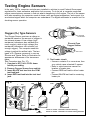
Testing Engine Sensors
In the early 1980s, computer controls were installed in vehicles to meet Federal Government
regulations for lower emissions and better fuel economy. To do its job, a computer-controlled
engine uses electronic sensors to find out what is happening in the engine. The job of the sensor
is to take something the computer needs to know, such as engine temperature, and convert it to
an electrical signal which the computer can understand. The digital multimeter is a useful tool for
checking sensor operation.
Titania-Type
Oxygen Sensor
Oxygen (O2) Type Sensors
Exposed
flat element
The Oxygen Sensor produces a voltage or
resistance based on the amount of oxygen in
the exhaust stream. A low voltage (high
resistance) indicates a lean exhaust (too
much oxygen), while a high voltage (low
resistance) indicates a rich exhaust (not
enough oxygen). The computer uses this
voltage to adjust the air/fuel ratio. The two
types of O2 Sensors commonly in use are
Zirconia and Titania. Refer to illustration for
appearance differences of the two sensor
types.
Test Procedure (see Fig. 27):
1. If engine is HOT, let it COOL down
before proceeding.
2. Remove Oxygen Sensor from vehicle.
3. Insert BLACK test lead into the COM
test lead jack.
4. Insert RED test lead into the test lead
jack.
Fig. 27
Flutes
5. Test heater circuit.
If sensor contains 3 or more wires, then
your vehicle uses a heated O2 sensor.
Refer to vehicle service manual for
location of heater pins.
Connect RED test lead to either heater
pin.
Connect BLACK test lead to remaining
heater pin.
Lean
Rich
4
750
CYL
200
RPM
X10
6
5
CYL
20
CYL
8
2
CYL
4
20M
CYL
5
2M
CYL
6
200K
OHMS
Zirconia-Type
Oxygen Sensor
CYL
8
20K
Red
CYL
2K 200
COM
DWELL
V
750V AC
200V DC
Black
1-wire or 3-wire: Ground is sensor housing
Ground
2-wire or 4-wire: Ground is in sensor wiring harness
28
Turn multimeter rotary switch to 200Ω
range.
View reading on display.
Compare reading to manufacturer's
specification in vehicle service manual.
Remove both test leads from sensor.
6. Connect BLACK test lead to sensor
GROUND pin.
If sensor is 1-wire or 3-wire, then
GROUND is sensor housing.
If sensor is 2-wire or 4-wire, then
GROUND is in sensor wiring harness.
Refer to vehicle service manual for
Oxygen Sensor wiring diagram.
7. Connect RED test lead to sensor
SIGNAL pin.
8. Test Oxygen Sensor.
Turn multimeter rotary switch to...
2V range for Zirconia Type Sensors.
200Ký range for Titania Type Sensors.
Light propane torch.
Firmly grasp sensor with a pair of
locking pliers.
Thoroughly heat sensor tip as hot as
possible, but not glowing. Sensor tip
must be at 660°F to operate.
Completely surround sensor tip with
flame to deplete sensor of oxygen (Rich
Condition).
Multimeter display should read...
0.6V or greater for Zirconia Type
Sensors.
an Ohmic(Resistance) value for Titania
Type Sensors. Reading will vary with
flame temperature.
While still applying heat to sensor, move
flame such that oxygen can reach
sensor tip (Lean Condition).
Multimeter display should read...
0.4V or less for Zirconia Type Sensors.
an overrange condition for Titania Type
Sensors. (See Setting the Range on
page 6.)
9. Repeat Step 8 a few times to verify
results.
10. Extinguish Flame, let sensor cool, and
remove test leads.
11. Test Results.
Good Sensor:
Heater Circuit resistance is within
manufacturer's specification.
Oxygen Sensor output signal changed
when exposed to a rich and lean
condition.
Bad Sensor:
Heater Circuit resistance is not within
manufacturer's specification.
Oxygen Sensor output signal did not
change when exposed to a rich and lean
condition.
Oxygen sensor output voltage takes
longer than 3 seconds to switch from a
rich to a lean condition.
29
Temperature Type Sensors
A temperature sensor is a thermistor or a
resistor whose resistance changes with
temperature. The hotter the sensor gets, the
lower the resistance becomes. Typical
thermistor applications are engine coolant
sensors, intake air temperature sensors,
transmission fluid temperature sensors, and
oil temperature sensors.
8. Turn multimeter rotary switch to
desired OHM range.
If the approximate resistance is unknown,
start at the largest OHM range and
decrease to the appropriate range as
required. (See Setting the Range on page
6)
9. View and record reading on display.
10.Disconnect multimeter test leads from
sensor and reconnect sensor wiring.
This step does not apply to intake air
temperature sensors. For intake air
temperature sensors, leave multimeter
test leads still connected to sensor.
11. Heat up sensor.
If testing Intake Air Temperature Sensor:
To heat up sensor dip sensor tip into
boiling water, or...
Heat tip with a lighter if sensor tip is
metal or a hair dryer if sensor tip is
plastic.
View and record smallest reading on
display as sensor is heated.
You may need to decrease the range to
get a more accurate reading.
For all other temperature sensors:
Start engine and let idle until upper
radiator hose is warm.
Turn ignition key OFF.
Disconnect sensor wiring harness and
reconnect multimeter test leads.
View and record reading on display.
12.Test Results.
Good Sensor:
Temperature sensors HOT resistance is
at least 300ý less than its COLD
resistance.
The key point is that the COLD
resistance decreases with increasing
temperature.
Bad Sensor:
There is no change between the
temperature sensors HOT resistance
from the COLD resistance.
The temperature sensor is an open or a
short circuit.
Fig. 28
Hair Dryer
4
750
CYL
200
RPM
X10
6
5
CYL
20
CYL
8
2
CYL
4
20M
CYL
5
2M
200K
OHMS
Typical
Intake Air
Temperature
Sensor
CYL
6
CYL
8
20K
CYL
2K 200
DWELL
Red
COM
V
750V AC
200V DC
Black
Test Procedure (see Fig. 28):
1. If engine is HOT let it COOL down
before proceeding.
Make sure all engine and transmission
fluids are at outside air temperature
before proceeding with this test!
2. Insert BLACK test lead into the COM
test lead jack.
3. Insert RED test lead into the V
test
lead jack.
4. Disconnect wiring harness from
sensor.
5. If testing Intake Air Temperature
Sensor - Remove it from vehicle.
All other temperature sensors can remain
on vehicle for testing.
6. Connect RED test lead to either sensor
pin.
7. Connect BLACK test lead to remaining
sensor pin.
30
Position Type Sensors
Position sensors are potentiometers or a type of
variable resistor. They are used by the computer to
determine position and direction of movement of a
mechanical device. Typical position sensor
applications are throttle position sensors, EGR
valve position sensors, and vane air flow sensors.
Fig. 29
Typical Toyota Throttle
Position Sensor
4
750
CYL
200
RPM
X10
6
5
CYL
20
CYL
8
2
CYL
4
20M
CYL
5
2M
CYL
6
200K
OHMS
CYL
8
20K
Black
Red
CYL
2K 200
COM
DWELL
V
750V AC
200V DC
POWER
SIGNAL
GROUND
IDLE SWITCH
Test Procedure (see Fig. 29):
1. Insert BLACK test lead into the COM
test lead jack.
2. Insert RED test lead into the V
test
lead jack.
3. Disconnect wiring harness from
sensor.
4. Connect Test Leads.
Connect RED test lead to sensor
POWER pin.
Connect BLACK test lead to sensor
GROUND pin.
Refer to vehicle service manual for
location of sensor POWER and
GROUND pins.
5. Turn multimeter rotary switch to 20KΩ
range.
6. View and record reading on display.
Display should read some resistance
value.
If multimeter is overranging, adjust the
range accordingly. (See Setting the
Range on page 6.)
If multimeter overranges on largest
range, then sensor is an open circuit
and is defective.
7. Move RED test lead to sensor
SIGNAL pin.
Refer to vehicle service manual for
location of sensor SIGNAL pin.
8. Operate Sensor.
Throttle Position Sensor:
Slowly move throttle linkage from
closed to wide open position.
Depending on hook-up, the display
reading will either increase or
decrease in resistance.
The display reading should either
start at or end at the approximate
resistance value measured in Step 6.
Some throttle position sensors have
an Idle or Wide Open Throttle (WOT)
switch in addition to a potentiometer.
To test these switches, follow the
Testing Switches test procedure on
page 13.
When you are told to operate switch,
then move throttle linkage.
Vane Air Flow Sensor:
Slowly open vane door from closed to
open by pushing on it with a pencil or
similar object. This will not harm sensor.
Depending on hook-up, the display
reading will either increase or decrease
in resistance.
The display reading should either start
at or end at the approximate resistance
value measured in Step 6.
Some vane air flow sensors have an
idle switch and an intake air
temperature sensor in addition to a
potentiometer.
To test idle switch see Testing Switches
on page 13.
When you are told to operate switch,
then open vane door.
To test intake air temperature sensor
see Temperature Type Sensors on page
30.
31
Manifold Absolute Pressure
(MAP) and Barometric
Pressure (BARO) Sensors
EGR Valve Position
Remove vacuum hose from EGR valve.
Connect hand vacuum pump to EGR
valve.
Gradually apply vacuum to slowly open
valve. (Typically, 5 to 10 in. of vacuum
fully opens valve.)
Depending on hook-up, the display
reading will either increase or decrease
in resistance.
The display reading should either start
at or end at the approximate resistance
value measured in Step 6.
9. Test Results.
Good Sensor: Display reading gradually
increases or decreases in resistance as
sensor is opened and closed.
Bad Sensor: There is no change in
resistance as sensor is opened or closed.
This sensor sends a signal to the
computer indicating atmospheric pressure
and/or engine vacuum. Depending on the
type of MAP sensor, the signal may be a dc
voltage or a frequency. GM, Chrysler, Honda
and Toyota use a dc voltage MAP sensor,
while Ford uses a frequency type. For other
manufacturers refer to vehicle service manual
for type of MAP sensor used.
Fig. 30
DC V
200
AC V OFF
4
750
CYL 5
RPM
X10
6
CYL
20
CYL
8
2
Frequency
Only
CYL
4
20M
CYL
DC
Only
5
2M
CYL
6
200K
OHMS
CYL
8
20K
CYL
2K 200
DWELL
COM
V
750V AC
200V DC
Black
Red
Red
15
Ground
10
0
30
5
25
20
Typical GM
MAP Sensor
C
B
A
VACUUM PUMP
To
Computer
Test Procedure (see Fig. 30):
1. Insert BLACK test lead into the COM
test lead jack.
2. For DC Volts type MAP sensor, insert
test lead
RED test lead into the V
jack.
For Frequency type MAP sensor, insert
test lead
RED test lead into the
jack.
32
3. Disconnect wiring harness and vacuum
line from MAP sensor.
4. Connect jumper wire between Pin A on
wiring harness and sensor.
5. Connect another jumper wire between
Pin C on wiring harness and sensor.
6. Connect RED test lead to sensor Pin B.
7. Connect BLACK test lead to good
vehicle ground.
8. Make sure test leads and jumper wires
are not touching each other.
9. Connect a hand held vacuum pump to
vacuum port on MAP sensor.
10. Turn Ignition Key ON, but do not start
engine!
11. Turn multimeter rotary switch to...
20V range for DC type MAP sensors.
4 Cylinder RPM X 10 position for
Frequency type MAP sensors.
12. View reading on display.
DC Volts Type Sensor:
Verify hand held vacuum pump is at 0 in.
of vacuum.
Display reading should be approximately
3V or 5V depending on MAP sensor
manufacturer.
Frequency Type Sensor:
Verify hand held vacuum pump is at 0 in.
of vacuum.
Display reading should be approximately
4770RPM ± 5% for Ford MAP sensors
only.
For other frequency type MAP sensors
refer to vehicle service manual for MAP
sensor specifications.
It is O.K. if last two display digits change
slightly while vacuum is held constant.
Remember to multiply display reading by
10 to get actual RPM.
To convert RPM to Frequency or vice
versa, use the following equation:
Frequency =
{Equation Only Valid for Multimeter in 4
Cylinder RPM X 10 Position}
13. Operate Sensor.
Slowly apply vacuum to MAP sensor Never exceed 20 in. of vacuum because
damage to MAP sensor may result.
Display reading should decrease in
voltage or RPM as vacuum to MAP
sensor is increased.
Refer to vehicle service manual for
charts relating voltage and frequency
drop to increasing engine vacuum.
Use equation above for Frequency and
RPM conversions.
14. Test Results.
Good Sensor:
Sensor output voltage or
frequency(RPM) are within manufacturers specifications at 0 in. of vacuum.
Sensor output voltage or
frequency(RPM) decrease with increasing vacuum.
Bad Sensor:
Sensor output voltage or
frequency(RPM) are not within
manufacturers specifications at 0 in. of
vacuum.
Sensor output voltage or
frequency(RPM) do not change with
increasing vacuum.
RPM
30
33
Mass Air Flow (MAF) Sensors
This sensor sends a signal to the computer
indicating the amount of air entering the
engine. Depending on the sensor design, the
signal may be a dc voltage, low frequency, or
high frequency type. The CP7676 can only
test the dc voltage and low frequency type
of MAF sensors. The high frequency type
output a frequency that is too high for the
CP7676 to measure. The high frequency type
MAF is a 3-pin sensor used on 1989 and
newer GM vehicles. Refer to vehicle service
manual for the type of MAF sensor your
vehicle uses.
Test Procedure (see Fig. 31):
1. Insert BLACK test lead into the COM
test lead jack.
2. For DC Volts type MAF sensor, insert
RED test lead into the V
test lead
jack.
For Low Frequency type MAF sensor,
insert RED test lead into the
test
lead jack.
3. Connect BLACK test lead to good
vehicle ground.
4. Connect RED test lead to MAF signal
wire.
Refer to vehicle service manual for
location of MAF signal wire.
You may have to backprobe or pierce
MAF signal wire in order to make
connection.
Refer to vehicle service manual for best
way to connect to MAF signal wire.
5. Turn Ignition Key ON, but do not start
engine!
6. Turn multimeter rotary switch to...
20V range for DC type MAF sensors.
4 Cylinder RPM X 10 position for Low
Frequency type MAF sensors.
7. View reading on display.
DC Volts Type Sensor:
Display reading should be approximately
1V or less depending on MAF sensor
manufacturer.
Low Frequency Type Sensor:
Display reading should be approximately
330RPM ± 5% for GM Low Frequency
MAF sensors.
For other Low Frequency type MAF
sensors refer to vehicle service manual
for MAF sensor specifications.
It is O.K. if last two display digits change
slightly while Key is ON.
Remember to multiply display reading by
10 to get actual RPM.
To convert RPM to Frequency or vice
versa, use equation below.
Fig. 31
DC V
200
AC V OFF
4
750
CYL 5
RPM
X10
6
CYL
20
CYL
8
2
Frequency
Only
CYL
4
20M
2M
CYL
6
200K
OHMS
CYL
8
20K
CYL
2K 200
DWELL
COM
V
750V AC
200V DC
Red
DC
Only
CYL
5
Black
Ground
Frequency =
Red
RPM
30
{Equation Only Valid for Multimeter in 4
Cylinder RPM X 10 Position}
FLOW
Typical GM 1988 & older
Low Frequency type
MAF Sensor
34
Electrical Specifications
DC Volts
Range: 2V, 20V, 200V
Accuracy : ±(1.0% rdg + 2 dgts)
8. Operate Sensor.
Start engine and let idle.
Display reading should...
increase in voltage from Key On
Engine OFF for DC type MAF sensors.
increase in RPM from Key On Engine
OFF for Low Frequency type MAF
sensors.
Rev Engine.
Display reading should...
increase in voltage from Idle for DC
type MAF sensors.
increase in RPM from Idle for Low
Frequency type MAF sensors.
Refer to vehicle service manual for
charts relating MAF sensor voltage or
frequency(RPM) to increasing air flow.
Use equation above for Frequency and
RPM conversions.
9. Test Results.
Good Sensor:
Sensor output voltage or frequency
(RPM) are within manufacturers
specifications at Key ON Engine OFF.
Sensor output voltage or frequency
(RPM) increase with increasing air flow.
Bad Sensor:
Sensor output voltage or frequency
(RPM) are not within manufacturers
specifications at Key ON Engine OFF.
Sensor output voltage or frequency
(RPM) do not change with increasing air
flow.
AC Volts
Range: 750V
Accuracy: ±(0.75% rdg + 2 dgts)
Resistance
Range:
200Ω, 2KΩ, 20KΩ, 200KΩ, 2MΩ, 20MΩ
Accuracy: ±(0.75% rdg + 2 dgts)
Dwell
Range: 4CYL, 5CYL, 6CYL, 8CYL
Accuracy: ±(3.0% rdg + 5 dgts)
RPM
Range: 4CYL, 5CYL, 6CYL, 8CYL
Accuracy: ±(3.0% rdg + 5 dgts)
35
36
FULL ONE (1) YEAR
WARRANTY
SPX Corporation, 15825 Industrial
Parkway, Cleveland, Ohio 44135, warrants to the
user that this unit will be free from defects in
materials and workmanship for a period of one
(1) year from the date of original purchase. Any
unit that fails within this period will be repaired
without charge when returned to the Factory. SPX
requests that a copy of the original, dated sales
receipt be returned with the unit to determine if
the warranty period is still in effect. This warranty
does not apply to damages caused by accident,
alterations, or improper or unreasonable use.
Expendable items, such as batteries, fuses, lamp
bulbs, flash tubes also are excluded from the
scope of this warranty. SPX CORPORATION
DISCLAIMS ANY LIABILITY FOR INCIDENTAL
OR CONSEQUENTIAL DAMAGES FOR
BREACH OF ANY WRITTEN WARRANTY ON
THE UNIT. Some states do not allow the
disclaimer of liability for incidental or consequential damages, so the above disclaimer may not
apply to you. This warranty gives specific legal
rights, and you may also have rights which vary
from state to state.
© 2005 SPX Coproration
All Rights Reserved.
GARANTIA COMPLETA
DE UN AÑO
SPX Corporation, 15825 Industrial
Parkway, Cleveland, Ohio 44135, EE.UU.,
garantiza al usuario que esta unidad estará libre
de defectos de materiales y mano de obra por un
(1) año a partir de la fecha de compra del
comprador original. Cualquier unidad que falle
dentro de este período será reparada opción de
SPX sin cargo cuando se regrese a la fábrica.
SPX requiere que un comprobante de compra
(recibo de venta) fechado acompañe la unidad
para determinar si está en garantía. Esta
garantía no es aplicable a daños causados por
accidente, alteraciones, usos impropios o no
razonables. Artículos consumibles, tales como
baterías, fusibles, lámparas y tubos de destello
quedan excluidos de esta garantía. SPX
Corporation rechaza cualquier responsabilidad
de daños incidentales o indirectos por
incumplimiento de cualquier garantía escrita de
la unidad. Algunos estados de los EE.UU. y
ciertos países no permiten el rechazo de
cualquier responsabilidad de daños incidentales
o indirectos, por lo que el rechazo anterior puede
no ser aplicable en su caso. Esta garantía
concede derechos legales específicos y es
posible que Ud. tenga otros derechos que varían
de estado a estado de los EE.UU. y de país a
país.
0002-001-2275