1
AAL
Programmer’s Manual
Volume 1
Second Edition
Corpus Callosum Corporation
515 South Boulevard
Evanston, Illinois 60202-3022
PUBLISHED BY PHYSICAL PROPERTY MEASUREMENTS, INC.
825 Chicago Ave, Suite E., Evanston, IL 60202.
Copyright © 2011 by Corpus Callosum Corporation. All rights reserved.
Trademarks referenced in this document:
Inferno, Dis, Styx and Limbo are registered trademarks of Vita Nuova Holdings Limited
in the United States and other countries.
dsPIC is a trademark of Microchip in the United States and other countries.
Exactus is a trademark of BASF.
Plan 9 is a registered trademark of Alcatel-Lucent.
PostScript is a registered trademark of Adobe Systems Incorporated.
POSIX is a registered trademark of the IEEE.
SYNRAD and Evolution are registered trademarks of SYNRAD, Inc.
Unicode is a registered trademark of Unicode, Inc.
UNIX is a registered trademark of The Open Group.
Preface
This version of the aero-acoustic levitator (AAL) is the culmination of many years of
research conducted by Physical Property Measurements, Inc. and its predecessors.
Insights gained in earlier versions have been further studied and expanded to enable
significantly improved system control and data collection tools.
This generation of the AAL replaces analog control systems with newly designed digi
tal electronics. This change has enabled new software-based systems to manage
everything from the transducer output, resonant frequency tracking, sensor feedback
optimization, to temperature control of the transducers. We have replaced manual
controls with automated processes that respond to dynamic components previously
inaccessible to the experimenter.
Significant portions of the architecture were influenced by systems research con
ducted by the Computing Science Research Center at Lucent Technologies, Bell Labs.
The firmware running in the AAL, the systems design, and implementation of the
front-end graphics environment using Inferno were all shaped by ideas introduced in
Plan 9 from Bell Labs. A key component of the AAL leverages the file service protocol
known as 9P2000 (9P) from Plan 9 and Inferno. The standardization on 9P as an
interface to the AAL has enabled a clean structure for developing the testing and
data collection tools required to calibrate and optimize the instrument. All of these
tools leverage software and documentation found in the Plan 9 and Inferno distribu
tions.
The utilities pscheck(1) and scanfreq(1) detail how using a 9P exported file system
can simplify the development of tools required for data collection and analysis. The
key system application console(1) uses 9P to monitor and control the acoustic sys
tem, extending the file system metaphor throughout its architecture. The programs
sensors(1) and pyro(1) utilize concurrent programming techniques of the Limbo lan
guage to simplify overall control of the system.
Many thanks are given to the early aero-acoustic levitator inventors as well as the
people who worked on and made the ideas of Plan 9 and Inferno available.
Jeffrey Sickel
Corpus Callosum Corporation
June 2011
INTRO(1)
INTRO(1)
NAME
intro – introduction to the Aero-Acoustic Levitator
DESCRIPTION
The aero-acoustic levitator (AAL) by Physical Property Measurements, Inc. leverages software
based on the Plan 9 and Inferno operating systems. Working with these influential ideas, espe
cially the network protocol 9P, has enabled a significant change in the overall systems design
used in this kind of instrument. The AAL combines real-time embedded controllers built into a
distributed cluster, front-end tools leveraging concurrent programming techniques, higher per
formance CPUs for numerical and graphics processing, and serial interfaces to various third
party devices.
In order to be more flexible, certain utilities used in the system are based on Plan 9 from User
Space, a port of many Plan 9 programs to Unix-like systems. Information about Plan 9, Inferno,
the 9P file protocol, and Plan 9 from User Space are available on-line.
The programs that make up the user interface and tool chain for calibration are written in the
language Limbo. Refer to Inferno documentation to learn more about the Limbo programming
language and the Dis virtual machine. Shell scripts in both Inferno and Linux terminals are
used to access the AAL file system. Additional grap programs enable quick plotting of common
data analysis tasks.
The console(1) is the primary interface for controlling the AAL. The interface provides a quick
reference to monitor system frequency and control the driving sound pressure level (SPL)
required for acoustic levitation and sample stabilization. Position and spin control parameters
can be easily set by the operator and logged as a part of the experimental record.
Commands
The front end software is built around command line programs and several graphics interfaces,
both described in section 1. The designers attempted to follow guidelines from various UNIX,
Plan 9, and Inferno tools when implementing all of the AAL components.
Firmware
The AAL communications controller uses the file protocol 9P to provide a file system interface
to end user applications as described in section 4. Familiarity with 9P, though not required, will
be beneficial to the AAL application programmer. The following documentation covers the data
structures and API required to tune programs and write additional utilities for the AAL.
Communication between the distributed nodes of the AAL uses a custom protocol called
AALCall described in section 3. The AALCall protocol eliminates the required response mes
sages found in 9P. This modification keeps the number of bytes transferred to a minimum.
SEE ALSO
Section
Section
Section
Section
Section
Section
(1)
(2)
(3)
(4)
(5)
(6)
describes general publicly accessible commands.
for Limbo modules, specific to the AAL.
for firmware documentation.
for file services (accessed by ‘mount’).
for file formats and system conventions.
for administrative modules and system services.
Plan 9
Inferno
9P
Plan 9 from User Space
http://plan9.bell-labs.com/plan9/
http://www.vitanuova.com/inferno/index.html
http://plan9.bell-labs.com/magic/man2html/5/intro
http://swtch.com/plan9port/
1
CALIBTRAN(1)
CALIBTRAN(1)
NAME
aal/calibtran – AAL transducer control board calibration
SYNOPSIS
aal/calibtran [ -d ] [ -l log ] -t transducer
DESCRIPTION
Calibtran is a utility for capturing transducer controller calibration data.
The options are:
-d
-l log
-t transducer
Sends additional debugging messages to standard error.
Write collected data to log file instead of the default t.txt
The transducer and controller board number [1-6] used for data collection.
The command line interface facilitates collection of measured voltage, current, voltage phase,
and current phase. Additional probes need to be attached to the backplane connection points
to measure the V-I phase delta, voltage and current.
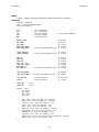
The commands are:
freq n
Set the operating frequency to n kilohertz.
gain n
Set the pre-amp output gain to n. The value is inverted with a zero output of 3584
and a maximum output of 512 .
m
Report the measured values from the transducer controller.
sdvi
Store and log the measured values including the entered delta, voltage, and current.
help/?
List a command summary.
quit
Exit the program and close the log file.
SOURCE
aal/appl/cmd/calibtran.b
SEE ALSO
calibtran(6)
2
CAPTURE(1)
CAPTURE(1)
NAME
capture – sensor phase data capture
SYNOPSIS
aal/sensor/capture [ -i file ] [ -r rawfile ] [ -s n ] [ -q ] [ sensor ]
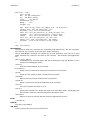
DESCRIPTION
Capture connects to a sensor, X, Y, or Z, already running in feedback mode and redirects to
standard out. The default is to only capture one second’s worth of sample data.
The options are:
-i file
read data from a file, do not connect to a sensor.
-r rawfile
write the data to rawfile instead of standard out.
-s n
sample for n seconds.
-q
quiet mode, do not dump data to standard out.
SOURCE
aal/appl/cmd/sensor/capture.b
3
CONSOLE(1)
CONSOLE(1)
NAME
console – a graphical AAL console
SYNOPSIS
aal/console [ -d ] [ -R path ] [ -r nsecs ] [ -s ]
DESCRIPTION
The AAL Console provides a graphical interface for monitoring and controlling an AAL device
mounted over aal9p(4).
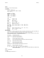
The console accepts several command line options:
-d
-R path
-r n
-s
Send additional debugging messages to standard error.
Override the default AAL root path, /n/aal, with the supplied path argument.
Set the reset counter modulus to n seconds.
Load data from /n/stats instead of the default /n/data.
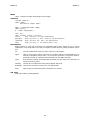
The console window is divided into two sections and additional pop-up windows described
below. The default system startup settings are: 0.0 SPL, 22.2 kHz, 0° and 180° phase between
each A and B transducers, feedback and SPL/Frequency tracking are off, and all fans are on.
All numeric entry fields (white background) support the use of the Up/Down arrows and
PgUp/PgDown keys. The arrows will increase or decrease the value in small, ones or thou
sands, steps. The page up/down keys increase or decrease in larger, tens or tenths, steps.
Main Frame
The main frame provides a heartbeat connection indicator to the AAL device and enables vari
ous system controls. The two entry fields SPL and Frequency provide a quick mechanism to set
the global state of the system.
The checkboxes on each row will track the SPL, frequency, and sensor feedback. The X, Y, and
Z boxes allow for finer grain control as to which axes are actually used during frequency and
sensor feedback tracking.
Valid ranges for the SPL entry field is between 0.0 and 2.0. Typing the number and pressing
the return/enter key will send a command to match the output of each transducer to the
desired SPL value and start SPL and frequency tracking. System operation does not require the
end user to update the frequency as that is tracked using algorithms to match the operating
resonant frequency of all six transducers.
The adjustments section provides the ability to update the Phase A offset and spin calibration
settings. Changing the phase A value will update the three axes to the offset entered. The off
set value does not persist when the console is exited and restarted. The spin button will adjust
all three axes spin values to their calculated A-B phase difference based on the equation
sd = sm(F − Fab) + offset where sm is the spin multiplier, F is the operating frequency, Fab is the
average of the resonant frequency of the A and B transducer.
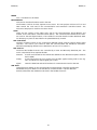
Transducer Axes Frame
All six controllers are represented by the three transducer axes frames: X, Y, and Z. Each
frame presents a quick view of the SPL, phase, spin, calculated A-B spin, fan state, and ampli
tude modulation. A plot view representing the phase relationship between the bottom, ’A’, and
top, ’B’, transducers is visible below the spin settings and next to an axis reset button.
The SPL entry fields are only valid when the track SPL checkbox is not enabled in the main
frame. Phase changes will move the standing wave on the given axis. The spin settings will
shift both the A and B phase relative to the other two axes. The modulation section provides a
mechanism to use amplitude modulation on a given transducer.
The spin button will update the spin settings to the value displayed in the field to the right of
the spin entry field. This value is continuly updated using the above A-B equation.
Clicking the reset button will return the axis to its default phase and spin settings: A=0 +
phase A offset°, B=180°, and spin=0°.
4
CONSOLE(1)
CONSOLE(1)
Scope Window
The scope button opens a graphical scope window. The X, Y, and Z spin settings are presented
on the left third of the window. The remaining two-thirds is split up into six graphs, one for
each transducer. The plots will show the operating voltage and current amplitude and phase.
Stats Window
The stats button opens a graphic view of the transducer controller settings. Each transducer
set values of the frequency and output (DAC) gain are visible. The Vo and Io are sampled 12bit values from the ADC on the transducer controller board. The φV and φI represent voltage
and current phase as determined in the phasedetector(3).
The lower section is populated with calculated values. The fields have a direct correlation to
the functions detailed in math(2).
FILES
$home/lib/transducer.cfg Stored calibration settings for each transducer.
SOURCE
aal/appl/wm/console.b
aal/appl/lib/scope.b
aal/appl/lib/stats.b
SEE ALSO
calibration(2), common(2), math(2), timedio(2).
5
DUMPBIN(1)
DUMPBIN(1)
NAME
dumpbin – dump TemperaSure file contents
SYNOPSIS
basf/dumpbin [ -a ] [ -o file ] [ - ] [ file... ]
DESCRIPTION
Dumpbin reads the contents of each TemperaSure binary formatted file and outputs a tabdelimited line for each record. If no file is specified then standard input is read.
The default usage will only output the time stamp and the temp0 fields. Use the -a flag to out
put the complete data record. The Exactus->Trecord data object elements represent in each
column are:
time
temp0
temp1
temp2
current1
current2
etemp1
etemp2
emissivity
A time stamp in milliseconds since the first record in the data set. All time
stamps are relative due to latency in the communication and processing of the
data. The data is in a guaranteed sequence.
The temperature measured from the main device.
Temperature reading from dual wavelength models. Typically zero.
Temperature reading from dual wavelength models. Typically zero.
Photodiode current in Amps form channel 1. Data will be zero if collection mode
of the Exactus has been set to temperature only.
Photodiode current in Amps from channel 2.
Internal device electronics temperature.
Internal device electronics temperature.
Calculated emissivity value from a table stored in the pyrometer, if enabled.
It will not be unusual for there to only be values in the timestamp and temp0 columns.
The option -o will write the output to the file instead of stdout.
FILES
~/logs/aal/exactus
SOURCE
basf/appl/cmd/dumpbin.b
SEE ALSO
pyro(1), exactus(2), temperasure-bin(5)
6
NOISECHECK(1)
NOISECHECK(1)
NAME
noisecheck – sensor detector noise check
SYNOPSIS
aal/sensor/noisecheck [ -s ] [ -v ] [ axis ]
DESCRIPTION
Noisecheck collects data from the sensors to assist in determining signal noise received by the
Hamamatsu position sensitive detector (PSD). The sensor firmware responds to a noisecheck
command by sending a stream of data in three columns. The values are the calculated veloc
ity, VposY, and the Vref sample.
The options are:
-s
Only run a single set sample set. Otherwise the user is prompted for three runs: one
with no filter, one with a 0.3 ND filter, and a final run with a 0.5 ND filter.
-v
Prompt the user for observable voltages when attaching an oscilloscope.
axis
The sensor to sample.
The output data will be written to a file or files in the current working directory.
FILES
X_noise.g
Produce a graph of X sensor noise.
Y_noise.g
Produce a graph of Y sensor noise.
Z_noise.g
Produce a graph of Z sensor noise.
SOURCE
aal/appl/cmd/sensor/noisecheck.b
7
PSCHECK(1)
PSCHECK(1)
NAME
pscheck – sensor position sensitivity check
SYNOPSIS
aal/sensor/pscheck [ -a ] [ -d ] [ -r ±range ] [ -s spl ] [ -t ] [ -v ] [ -Y ] [ axis ]
DESCRIPTION
Pscheck requires the use of a polystyrene bead for sensor position sensitivity scans. The
resulting scan data is used to calibrate the sensor feedback gain. Data files are collected for all
three sensors X, Y, and Z, and stored in the current working directory. The data files are
named pscheck_Nn.d where ’N’ is the axis of sample translation and ’n’ is the sensor being
measured.
The options are:
-a
Run check using all transducers. Otherwise only the single axis transducers will be
on during the run.
-d
Sends additional debugging messages to standard error.
-r range Set the ±range from a centered zero position that will be scanned.
-s spl
Set the SPL value. Default is 0.6.
-t
Turn off the SPL and frequency tracking.
-v
Prompts the user for VposY and Vref peak-to-peak measurements at each position.
-Y
Automatically take the defaults at each prompt.
axis
Sets the axis for translating the sample.
Measurements are taken across the range at 10 degree intervals outside of ±40 degrees and
at 2 degree intervals between the ±40 degree range. The A (bottom) transducer is the only
one that changes its phase. If the -a flag is not used, then an axis is required for the scan as all
of the other transducers will be turned off during the run.
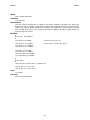
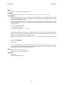
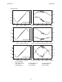
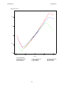
Data collected from the run can be processed with additional programs to determine the pro
portional gain to use on each sensor.
EXAMPLE
Start up the aal/console and run the SPL at 0.6 for a few minutes to let the transducer fre
quency tracking work. Bring up a shell and start the pscheck:
aal/sensor/pscheck -a -r 200
Follow the instructions to complete the data collection run. On completion, the user can take
the pscheck_??.d files and run them through provided grap | troff programs or any other data
analysis tool. The file is tab delimited with the column formats:
1
Velocity
2
Sum of the last ten VposY measurements.
3
Sum of the last ten Vref measurements.
4
Sample position in degrees phase from 0.
FILES
pscheck.g
Produce a graph of all three sensors on each axis.
pscheckfit.g
Produce a graph of the X, Y, and Z axes by averaging each phase point from
the data set collected.
pscheckfit2.g
Produce a consolidated graph using averaging for each phase point. Each of
the axes are centered at the 0° point before being plotted.
SOURCE
aal/appl/cmd/sensor/pscheck.b
SEE ALSO
pscheck(6)
8
PYRO(1)
PYRO(1)
NAME
pyro – graphical pyrometer robotic positioning tool
SYNOPSIS
aal/pyro [ -d ] [ -c config ] [ -e path ] [ -l ] [ -s ] [ -z path ]
DESCRIPTION
Pyro controls the Zaber linear translators used to position the Exactus pyrometer for optimal
temperature measurements. The tool presents a graphical representation of the current posi
tion of the pyrometer. The user can click in the graphic frame or key in millimeter XY values to
position the pyrometer. Button controls can center, return to chessman (saved) position, and
scan a region. Any modifications to the position or scan regions can be saved from the file
menu.
All text entry fields respond to keyboard up and down arrow and page-up and page-down keys
in the following manner:
page-up
Move up or right by 1mm.
arrow-up
Move up or right by 0.125mm.
arrow-down
Move left or down by 0.125mm.
page-down
Move left or down by 1mm.
Options
-d
Send additional debugging information to standard error.
-cconfig Use configuration file provided instead of default $home/lib/pyro.cfg .
-epath
Connection to Exactus path instead of the default tcp!iolan!exactus.
-l
Do not create scan log files.
-s
Run data simulator instead of requiring an Exactus connection.
-zpath
Connect to Zaber through path instead of the default tcp!iolan!zaber.
The scan region X and Y buttons will open up a new window to plot data as the Zaber translator
moves the Exactus across the provided axis. After the scan has been completed the user may
set a new desired position by clicking near the temperature line in the scan window. The click
will move the Exactus into the position and leave a mark on the view indicating the change.
Clicking anywhere in the window outside of five pixels from the temperature line will not move
the Exactus.
FILES
$home/lib/pyro.cfg
$home/logs/aal/exactus
SOURCE
aal/appl/wm/pyro.b
SEE ALSO
exactus(2), pyroplot(2), zaber(2)
9
SCANFREQ(1)
SCANFREQ(1)
NAME
scanfreq – acoustic frequency scanner
SYNOPSIS
aal/scanfreq [ -d ] [ -g gain ] [ -l low kHz ] [ -h high kHz ] [ -m ms ]
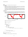
DESCRIPTION
Scanfreq runs a frequency scan at a given gain within the range of low to high frequencies and
prints to standard output. It polls data from the AAL device mounted at /n/aal every ms mil
liseconds after setting the frequency. The scan starts at the high frequency, steps down in 2
Hz intervals until the low frequency is reached. The scan continues back to the high frequency.
The options are:
-d
Send additional debugging information to standard error.
-g gain
Set the fixed gain value. Minimum (zero) is 3584, maximum is 512.
-l low
Set the lowest frequency in the scan, minimum is 22.1 kHz.
-h high
Set the highest frequency in the scan, maximum is 22.3 kHz.
-m ms
Set the millisecond delay for measuring data after the frequency is set.
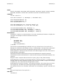
EXAMPLE
aal/scanfreq -g 2500 -l 22.13 -h 22.24 -m 500 > g2500.txt
FILES
/n/aal/data
SOURCE
aal/appl/cmd/scanfreq.b
SEE ALSO
scanfreq(6)
BUGS
The ms setting must be coordinated with the AAL communication board to transducer controller
board polling frequency.
10
SENSORS(1)
SENSORS(1)
NAME
sensors – graphical feedback sensor tool
SYNOPSIS
aal/sensors [-d ] [ -c config ] [ -h host ]
DESCRIPTION
Sensors provides a graphical interface to monitor and control the three AAL feedback sensors.
The command options are:
-d
Send additional debugging information to standard error.
-c config
Use provided config file instead of the default $home/lib/sensor.cfg .
-h host
Connect to host network address.
On startup the user will need to connect to the sensors. This can be accomplished either glob
ally from the top All: Connect button, or on a per axis basis. A successful connection will popu
late the status fields Laser kHz, Switch ON, Switch OFF, Gain, and Cap. These status fields
report the current state of the sensor system.
Feedback is turned on by entering a gain value and enabling the feedback (fb) checkbox. Plots
on the right present the X, Y, and Z axes data received by the transducer controllers. These
plots help the user monitor sensor noise levels and velocity phase corrections.
The entry fields gain, slope, and cmd are the user tools for changing parameters of the feed
back system. Entering a gain value and pressing return will send a command to change the
gain to all connected sensors. On success the sensor gain field will display the entered value
multiplied by the proportional gain. The gain displayed is applied to the detected VposY/Vref
ratio to create a phase change at the transducer.
The slope fields display the stored value from the sensor.cfg file. These values are used to cal
culate the proportional gain applied to the global gain value for each sensor. Updates are usu
ally made after running pscheck(1). The file menu "Save Profile" will save the slope values for
future use in the application.
The cmd field is used to send additional commands to the sensor. The commands are:
Kd=n
Set the gain to n divided by 100.
cap=n
Set the maximum phase change cap to n. The default is 256 where 127 ≅ 11.54°.
mod=n
Set the laser modulation to n Hz where n is ≥ 100.0.
swtchon=n Toggle the switching state on n microseconds after the laser modulation change.
The default is 220 (6µs).
swtchoff=n Toggle the switching state off n microseconds after the laser modulation change.
The default is 397 (10.8µs).
FILES
$home/lib/sensor.cfg
SEE ALSO
pscheck(1), sensor(3)
BUGS
Connect and disconnect button toggling does not properly represent state if the network is
down.
11
SIM(1)
SIM(1)
NAME
sim – sensor output simulator
SYNOPSIS
aal/tests/sim [ -a amp ] [ -d ] [ -f freq ] [ -h hz ] [ -w func ] [ path ]
DESCRIPTION
Sensorsim (sim) is a program used to generate output data in the same format as the
position/velocity feedback system in the AAL. It was initially designed as a testing framework
for controlling transducer phase feedback changes. Later it proved to be a good mechanism to
prove out the sensor plot code used in sensors(1).
The options are:
-aamp
Sets the output amplitude, default is 10.0.
-d
Emits received input to stdout.
-ffreq
Sets the output frequency of the function.
-hHz
Sets the frequency of the output sent by the simulator.
-wfunc
Start with the function out of: random, sawtooth, sine, square, or triangle.
path
The control file path. This may be either a file path for reading/writing or a network
address to announce a listener for incoming connections.
SOURCE
aal/appl/tests/sensorsim/sim.b
12
TIMING(1)
TIMING(1)
NAME
timing – sensor timing test tool
SYNOPSIS
aal/sensor/timing sensor
DESCRIPTION
Timing runs a series of communications tests on the X, Y, or Z position sensor. Each set of
tests is run ten times and averaged. The final output result is in milliseconds. Reported ADC
samples are from 40K samples/second with every ten samples being averaged and stored for
use in the sample counter. A millisecond timer is used on the user’s computer and ends up
measuring the start and end time. Attempts are made to accommodate for the start and stop
text transmission being counted in the total time. The tests are:
1000
ADC samples, no PID
1000
ADC samples, with PID, no output
1000
ADC samples, with PID, transmit 3 byte output
1000
Noisecheck outputs, PID with Yn, P, D, Vposyn, Vrefn
13
UC2K(1)
UC2K(1)
NAME
uc2k – graphical Synrad laser controller interface
SYNOPSIS
aal/uc2k [ -c ] [ -d ]
DESCRIPTION
Uc2k is a simple interface to the Synrad UC-2000 laser controllers. The AAL uses two con
trollers, labeled one and two. The interface allows for either one, two, or both laser controllers
to be used to control the pulse width modulation (PWM) and lase on/off settings.
After starting the program, the user must initiate the serial connection to the controller. This is
handled through two buttons to the left and right of the labels 1 and 2. The buttons will turn
green when the connection is made. Closing the connection will shut off the laser.
The PWM fields are used to manually control the values sent to the controller. All text fields will
also respond keyboard up and down arrow keys as well as page-up and page-down in the fol
lowing manner:
page-up
Increase PWM by 5.0%.
arrow-up
Increase PWM by 0.5%.
arrow-down
Decrease PWM by 0.5%.
page-down
Decrease PWM by 5.0%.
a A z Z
Set PWM to 0.0% and turn LASE off.
The 1, LASE, and 2 buttons are used to turn the lasers on and off. When the laser is on the cor
responding button will have a red background. Use the LASE button to turn both controllers on
or off simultaneously.
OPTIONS
-c
-d
Do not use a checksum when communicating with the UC-2000 Controller. This allows
uc2k use on UC-2000 Controller firmware versions prior to v2.4 or when the checksum
feature has been disabled.
Output additional debugging information to standard error.
FILES
$home/logs/aal/uc2k/
SOURCE
aal/appl/cmd/synrad/uc2k.b
SEE ALSO
uc2000 (2)
BUGS
The use of dial in the uc2000 (2) module does not handle connections well when the UC con
trollers are not turned on by the operator.
14
INTRO(2)
INTRO(2)
NAME
intro – introduction to Limbo modules specific to the AAL
SYNOPSIS
include
include
include
include
"aalutil.m";
"common.m";
"calibration.m";
"aalmath.m";
util: AALUtil;
common: AALCommon;
aalwrite, comm, Tstats: import common;
aal: AALCalibration;
Tprofile: import aal;
aalmath: AALMath;
... etc.
DESCRIPTION
This section introduces the Limbo modules available to the AAL programmer. Corresponding
manual pages describe each of the modules specific to the AAL, Exactus communication, Mod
bus protocol, Synrad laser controllers, and the Zaber linear translators.
The Inferno programmer’s manual should be referenced for more details about Limbo and
related technologies.
15
CALIBRATION(2)
CALIBRATION(2)
NAME
calibration – AAL calibration parameters
SYNOPSIS
include "calibration.m";
aal: AALCalibration;
Tprofile: import aal;
Tprofile: adt {
Bid: string;
Bsn: string;
Tsn: string;
IVPc: real;
Av:
real;
Ai:
real;
Aspl: real;
Ag:
real;
Bg:
real;
A1:
real;
A0:
real;
#
#
#
#
#
#
AAL board id/slot
AAL board serial number
Transducer serial number
IV Phase count constant (frequency from dsPIC33F)
Voltage calibration
Current calibration
cmp: fn (a, b: ref Tprofile): int;
new: fn (bid: string): ref Tprofile;
};
tprofiles: array of ref Tprofile;
boardprofile: fn (i: int): ref Tprofile;
readfile: fn (filename: string): int;
writefile: fn (filename: string, perm: int): int;
readconfig: fn (filename: string): int;
writeconfigfile: fn (filename: string, perm: int): int;
writeconfig: fn (fd: ref Sys->FD): int;
DESCRIPTION
AALCalibration provides the reference Tprofile data structure for all transducer and controller
boards. The profiles are loaded by console(1) on start up and used in math(2) to calculate fre
quency and SPL values. There are six instances of Tprofile in the global tprofiles array, one for
each transducer–controller pair. The calls implemented are:
cmp
new
boardprofile
readfile
writefile
readconfig
writeconfigfile
writeconfig
Compares two Tprofile instances.
Allocates a new Tprofile instance.
Returns the Tprofile for a provided board id (1-6).
Reads a tab-delimited configuration file and fills tprofiles with new
instances of Tprofile.
Writes the array tprofiles to a tab-delimited file named by path.
Reads in a s-expression configuration file and fills tprofiles with new
instances of Tprofile.
Writes the array tprofiles to a s-expression file.
Writes the array tprofiles in s-expression format to the supplied file descrip
tor.
SOURCE
aal/appl/lib/calibration.b
SEE ALSO
calibtran(1), capture(1), console(1), scanfreq(1), math(2), calibtran(6)
16
COMMON(2)
COMMON(2)
NAME
common – AAL common module
SYNOPSIS
include "common.m";
common := load AALCommon AALCommon->PATH;
common->init();
Tstats: adt {
online: int;
name:
string;
gain:
int;
freq:
int;
phase: int;
mper:
int;
mfreq: real;
flags: byte;
Vo:
int;
PhiV:
int;
Io:
int;
PhiI:
int;
debug: fn(s: self ref Tstats): int;
feedback: fn(s: self ref Tstats): int;
fan:
fn(s: self ref Tstats): int;
};
tstats: array of ref Tstats;
boardaxis: fn(bid: int): string;
boardstats: fn(bid: int): ref Tstats;
frequency: fn(t: ref Tstats): real;
gaintopercent: fn (g: int): real;
percenttogain: fn (p: real): int;
degreetophase: fn (deg: real): int;
phasetodegree: fn (p: int): real;
parsetstat: fn (line: string): Tstats;
updatestats: fn (sfd: ref Sys->FD): int;
reloaddata: fn(fd: ref Sys->FD): int;
aalread: fn (path: string): string;
aalwrite: fn(path: string, cmd: string): int;
secondtimer: fn (sync: chan of int);
timer: fn (tick: chan of int, ms: int);
isnumber: fn (s: string): int;
GAINMAX:
con
GAINMIN:
con
GAINDEFAULT:
FREQMIN:
con
FREQMAX:
con
FREQDEFAULT:
PHASEMIN:
con
PHASEMAX:
con
PHASEDEFAULT:
AD9384PTWOPI:
PHASERES:
con
AD9384FTWOPI:
FREQRES:
con
DDSDegree: con
512;
#
3584;
#
con GAINMIN;
22.0000;
#
22.2500;
#
con 22.2000;
0.0;
360.0;
#
con PHASEMIN;
con real 2**12;
#
real (360. / AD9384PTWOPI);
con real 2**28;
#
8000000.0 / AD9384FTWOPI;
real 11.3778;
#
17
this one goes to 2^9
a baseline for zero 2^12-2^9
Firmware allows down to 22.0 kHz
Firmware max set to 22.3 kHz
degrees
Analog Devices 9384 Phase 2pi
Analog Devices 9384 Frequency 2pi
1/360 == x/4096
COMMON(2)
COMMON(2)
DESCRIPTION
AAL common module provides a Limbo interface to reading, writing, modifying, and displaying
AAL statistics from the aal9p(4) file system. Init must be called before any other function in
this module.
The type Tstats represents the available statistics for an individual transducer controller board
in the AAL. The array tstats, initialized in the init function, stores all six transducers statistics
and is updated through the updatestats and reloaddata functions covered below.
The data objects in Tstats are:
online
The current state of the controller board, on=1.
name
The transducer controller board slot name, t1–t6.
gain
Integer value written to the DAC.
freq
The frequency in decihertz.
phase
The integer phase value set to the DDS.
mper
The modulation percent multiplied by 100.
mfreq
The modulation frequency in hertz.
flags
A byte representing the bit field flags.
Vo
The ADC measured voltage output to the transducer.
PhiV
An integer counter for the voltage phase.
Io
The ADC measured current output to the transducer.
PhiI
An integer counter for the current phase.
The following convenience functions are provided by Tstats:
debug
Return the debug bit from the flags byte.
fan
Return the fan bit from the flags byte.
feedback
Return the feedback bit from the flags byte.
The principal functions used to access data are updatestats and reloaddata. Both take a file
descriptor as their parameter to read a new set of data from the AAL controller and fill the
tstats array. Updatestats parses the textual data in /n/aal/stats. Reloaddata does a binary
read of /n/aal/data to populate the array. The /n/aal/data file is less than half the size of
the stats file and thus more useful over the slow communications link.
FILES
/n/aal/stats
SOURCE
aal/appl/lib/common.b
SEE ALSO
console(1), aal9p(4)
18
EXACTUS(2)
EXACTUS(2)
NAME
exactus – Exactus pyrometer interface
SYNOPSIS
include "exactus.m";
exactus := load Exactus Exactus->PATH;
EPort: adt
{
mode:
maddr:
temp:
rate:
path:
ctl:
data:
wdata:
rdlock:
wrlock:
buffer:
pids:
tchan:
ms:
int;
int;
real;
int;
string;
ref Sys->FD;
ref Sys->FD;
ref Sys->FD;
ref Lock->Semaphore;
ref Lock->Semaphore;
array of byte;
list of int;
chan of ref Exactus->Trecord;
int;
write:
getreply:
readreply:
#
#
#
#
Exactus or Modbus
Modbus address
Last measured temperature
Graph rate
# bytes from reader
# ms start of last packet
fn(p: self ref EPort, b: array of byte): int;
fn(p: self ref EPort): (ref ERmsg, array of byte, string);
fn(p: self ref EPort, ms: int): (ref ERmsg, array of byte, string);
};
Emsg: adt {
pick {
Temperature =>
degrees:
Current =>
amps:
Dual =>
degrees:
amps:
Device =>
edegrees:
cdegrees:
Version =>
mode:
appid:
vermajor:
verminor:
build:
Acknowledge =>
c:
}
temperature:
current:
dual:
device:
acknowledge:
unpack:
text:
real;
real;
real;
real;
real;
real;
byte;
byte;
int;
int;
int;
byte;
fn(m:
fn(m:
fn(m:
fn(m:
fn(m:
fn(b:
fn(m:
self ref
self ref
self ref
self ref
self ref
array of
self ref
};
19
Emsg):
Emsg):
Emsg):
Emsg):
Emsg):
byte):
Emsg):
real;
real;
(real, real);
(real, real);
byte;
(int, ref Emsg);
string;
EXACTUS(2)
EXACTUS(2)
ETmsg: adt {
pick {
Readerror =>
error:
ExactusMsg =>
msg:
ModbusMsg =>
addr:
msg:
crc:
}
string;
ref Emsg;
byte;
ref Modbus->TMmsg;
int;
packedsize: fn(nil: self ref ETmsg): int;
pack:
fn(nil: self ref ETmsg): array of byte;
dtype:
fn(nil: self ref ETmsg): (ref Emsg, ref Modbus->TMmsg);
};
ERmsg: adt {
pick {
Readerror =>
error:
ExactusMsg =>
msg:
ModbusMsg =>
msg:
}
packedsize:
pack:
dtype:
tostring:
string;
ref Emsg;
ref Modbus->RMmsg;
fn(nil:
fn(nil:
fn(nil:
fn(nil:
self
self
self
self
ref
ref
ref
ref
ERmsg):
ERmsg):
ERmsg):
ERmsg):
int;
array of byte;
(ref Emsg, ref Modbus->RMmsg);
string;
};
Trecord: adt {
time: int;
temp0:
temp1:
temp2:
current1:
current2:
etemp1:
etemp2:
emissivity:
pack:
unpack:
real;
real;
real;
real;
real;
real;
real;
real;
fn(nil: self ref Trecord): array of byte;
fn(b: array of byte): (int, ref Trecord);
};
Tdatafile: adt {
name:
string;
count:
int;
startTime: string;
IsDataDwl: int;
dataVersion: int;
tempValid: int;
currentValid: int;
serial:
string;
};
# should be unsigned 32-bit
# YYYY-MM-DD HR:mm:ss
# Always 3
20
EXACTUS(2)
init:
debug:
EXACTUS(2)
fn();
fn(f: int);
open:
close:
readreply:
write:
exactusmode:
modbusmode:
swapendian:
escape:
deescape:
lrc:
ieee754:
graphrate:
set_graphrate:
serialnumber:
temperature:
fn(path: string): ref Exactus->EPort;
fn(p: ref EPort): ref Sys->Connection;
fn(p: ref EPort, ms: int): (ref ERmsg, array of byte, string);
fn(p: ref EPort, b: array of byte): int;
fn(p: ref EPort);
fn(p: ref EPort);
fn(b: array of byte): array of byte;
fn(buf: array of byte): array of byte;
fn(esc: byte, buf: array of byte, n: int): (int, array of byte);
fn(buf: array of byte): byte;
fn(b: array of byte): real;
fn(p: ref EPort): int;
fn(p: ref EPort, r: int);
fn(p: ref EPort): string;
fn(p: ref EPort): real;
DESCRIPTION
Exactus provides an interface for controlling an Exactus pyrometer. After calling init() a pro
gram will open() a new EPort in order to interact with the serial protocols supported by the
Exactus device. On successfully opening a new EPort a custom reader process will be
spawned off and will be managed by the module. The reader handles the two protocols sup
ported by an Exactus device, Modbus and a legacy streaming Exactus mode. The Exactus
module supports near transparent negotiation of the two protocols to enable data collection
and control of the device.
The module handles modbus(2) protocol dependencies for setting sampling rates and mode
negotiation. A user program will use the following functions:
set_graphrate(p, r)
graphrate(p)
temperature(p)
exactusmode(p)
modbusmode(p)
Sets the Exactus graph rate (sampling rate) to r, (1–1000).
Return the operating sampling rate.
Read and return the temperature in Celsius, from an IEEE–754
32–bit float.
Turn on Exactus mode streaming of temperature data.
Turn off data streaming.
A client application will populate the EPort.tchan to be able to receive and process streamed
data in an alt loop. A Trecord data object pack() is called to produce the array of bytes to be
written to a TemperaSure log file.
SOURCE
aal/sys/src/basf/appl/lib/exactus.b
SEE ALSO
dumpbin(1), pyro(1), modbus(2), pyroplot(2), temperasure-bin(5)
BUGS
Opening a direct serial port connection fails to properly negotiate the modbus(2) transport pro
tocol.
21
MATH(2)
MATH(2)
NAME
aalmath – floating point resonant frequency and SPL functions
SYNOPSIS
include "aalmath.m";
aalmath := load AALMath AALMath->PATH;
ampvolt: fn(tp: ref Tprofile, ts: ref Tstats): real;
ampcurrent: fn(tp: ref Tprofile, ts: ref Tstats): real;
amppower: fn(tp: ref Tprofile, ts: ref Tstats): real;
ivphasediff: fn(tp: ref Tprofile, ts: ref Tstats): real;
trueivphasediff: fn(tp: ref Tprofile, ts: ref Tstats): real;
gainvsvolts: fn(tp: ref Tprofile, ts: ref Tstats): real;
measuredspl: fn(tp: ref Tprofile, ts: ref Tstats): real;
resonantfreq: fn(tp: ref Tprofile, ts: ref Tstats): real;
sign: fn(a: real): real;
splgain: fn(s: real, tp: ref Tprofile, ts: ref Tstats): int;
splpower: fn(s: real, tp: ref Tprofile): real;
DESCRIPTION
These functions are used to track resonant frequency and SPL. The reference parameter
Tprofile is a calibration profile for a transducer and controller board pair. The reference param
eter Tstats is the most recently measured data from a given transducer controller board.
The function apmvolt returns the peak–to–peak voltage supplied to the transducer.
The function ampcurrent returns the peak–to–peak current measured across a 1–ohm resistor.
The ivphasediff function returns the measured current–voltage phase difference of the ampli
fier output.
Trueivphasediff just returns the ivphasediff result. This is a stub from a prior version of the
AAL hardware that required the application of a 14° phase shift.
The function amppower is the total power delivered to the transducer.
The measuredspl function returns the measured SPL value, a calibration times the square root
of the power.
Splpower returns the new power required to achieve a given SPL.
The gainvsvolts function is the voltage produced by the DAC gain and calibration parameters.
This value is used primarily as a data point and not for further functions.
The splgain function calculates the new DAC gain value required to achieve a given SPL.
The function resonantfreq is the resonant frequency vs the current–voltage phase.
Calibration
The Tprofile adt is calculated with the use of the calibtran, and scanfreq programs. This data is
loaded from the transducer.cfg file by calibration(2).
SOURCE
aal/lib/math.b, $home/lib/transducer.cfg
SEE ALSO
calibtran(1), scanfreq(1), calibration(2), common(2)
22
MODBUS(2)
MODBUS(2)
NAME
modbus – Modbus protocol
SYNOPSIS
include "modbus.m";
modbus: Modbus;
TMmsg, RMmsg: import modbus;
modbus = load Modbus Modbus->PATH;
modbus->init();
TMmsg: adt {
frame: int;
addr: int;
check: int;
pick {
Readerror =>
error: string;
Error =>
fcode: byte;
ecode: byte;
Readcoils =>
offset:
int;
quantity: int;
Readdiscreteinputs =>
offset: int;
quantity: int;
Readholdingregisters =>
offset: int;
quantity: int;
Readinputregisters =>
offset: int;
quantity: int;
Writecoil =>
offset: int;
value: int;
Writeregister =>
offset: int;
value: int;
Readexception =>
s: string;
Diagnostics =>
subf: int;
data: int;
Commeventcounter =>
s: string;
Commeventlog =>
s: string;
Writecoils =>
offset: int;
quantity: int;
count: int;
data: array of byte;
Writeregisters =>
offset: int;
quantity: int;
count:
int;
data: array of byte;
Slaveid =>
s: string;
# 1 or 2 bytes
# 0 or 2 bytes
# 2
bytes, 0x0000 to 0xFFFF
# 2 bytes, 0x0001 to 0x07D0
# 2 bytes, 0x0001 to 0x007D
# 2 bytes, 0x0001 to 0x007D
# 2 bytes 0x0000 or 0xFF00
# 2 bytes 0x0000 to 0xFFFF
# not used
# 2 bytes, sub-function type
# 2 bytes
# not used
# not used
# 2 bytes, 0x0001 to 0x007B
# 1 byte
# not used
23
MODBUS(2)
MODBUS(2)
Readfilerecord =>
count: int;
data: array of byte;
Writefilerecord =>
count: int;
data: array of byte;
Maskwriteregister =>
offset: int;
andmask: int;
ormask: int;
Rwregisters =>
roffset: int;
rquantity: int;
woffset: int;
wquantity: int;
count:
int;
data: array of byte;
Readfifo =>
offset: int;
Encapsulatedtransport =>
meitype: byte;
data: array of byte;
}
read:
packedsize:
pack:
unpack:
text:
mtype:
# 1 byte, 0x07 to 0xF5
# 1 byte, 0x09 to 0xFB
# 2 bytes
# 2 bytes
# 2 bytes
#
#
#
#
#
#
2
2
2
2
1
2
bytes
bytes
bytes
bytes
byte
* count
fn(fd: ref Sys->FD, msglim: int): ref TMmsg;
fn(nil: self ref TMmsg): int;
fn(nil: self ref TMmsg): array of byte;
fn(b: array of byte, h: int): (int, ref TMmsg);
fn(nil: self ref TMmsg): string;
fn(nil: self ref TMmsg): int;
};
RMmsg: adt {
frame: int;
addr: int;
check: int;
pick {
Readerror =>
error: string;
Error =>
fcode: byte;
ecode: byte;
Readcoils =>
count: int;
data: array of byte;
Readdiscreteinputs =>
count: int;
data: array of byte;
Readholdingregisters =>
count: int;
data: array of byte;
Readinputregisters =>
count: int;
data: array of byte;
Writecoil =>
offset: int;
value: int;
Writeregister =>
offset: int;
# coil status
# inputs
# registers, N (of N/2 words)
# input registers, N (of N/2 words)
24
MODBUS(2)
MODBUS(2)
value: int;
Readexception =>
data: byte;
Diagnostics =>
subf: int;
data: int;
Commeventcounter =>
status: int;
count: int;
Commeventlog =>
count: int;
status: int;
ecount: int;
mcount: int;
data: array of byte;
Writecoils =>
offset: int;
quantity: int;
Writeregisters =>
offset: int;
quantity: int;
Slaveid =>
count: int;
data: array of byte;
Readfilerecord =>
count: int;
data: array of byte;
Writefilerecord =>
count: int;
data: array of byte;
Maskwriteregister =>
offset: int;
andmask: int;
ormask: int;
Rwregisters =>
count: int;
data: array of byte;
Readfifo =>
count: int;
fcount: int;
data: array of byte;
Encapsulatedtransport =>
meitype: byte;
data: array of byte;
}
read:
packedsize:
pack:
unpack:
text:
mtype:
# 2 bytes, sub-function type
# 2 bytes
# 2 bytes
# 1
# 2
# 2
# 2
# events:
byte
bytes
bytes
bytes
(N-6) * byte
# 2 bytes, 0x0001 to 0x07B0
# device specific
# 1 byte, 0x07 to 0xF5
# 2 bytes
# 2 bytes
# 2 bytes
# 2 bytes
# 2 bytes, ≤31
fn(fd: ref Sys->FD, msize: int): ref RMmsg;
fn(nil: self ref RMmsg): int;
fn(nil: self ref RMmsg): array of byte;
fn(b: array of byte, h: int): (int, ref RMmsg);
fn(nil: self ref RMmsg): string;
fn(nil: self ref RMmsg): int;
};
DESCRIPTION
The Modbus module provides an interface for reading and writing Modbus messages. The mod
ule does not provide a reader as that will be a requirement for the application developer. It
does provide all the functions necessary to encode and decode Modbus messages from arrays
of bytes. The exactus(2) module implements a reader that uses the Modbus protocol.
25
MODBUS(2)
MODBUS(2)
The data types for encapsulating Modbus messages are TMmsg for transmitting request mes
sages to a server and RMmsg to handle the response message. End user programs will need to
target the specific coils and registers for the device in question. For example:
m := ref TMmsg.Readholdingregisters(Modbus->FrameRTU, p.maddr, -1, 16r1305, 16r0009);
write(fd, m.pack());
will send a request to read the Modbus holding registers in RTU mode to the Exactus pyrometer
connected on fd. The request is for nine bytes of data representing the device serial number.
The RMmsg->unpack() function is used to decode an array of bytes. On success it will return a
valid RMmsg.
SOURCE
aal/sys/src/modbus/appl/lib/modbus.b
aal/sys/src/modbus/appl/cmd/testmodbus.b
SEE ALSO
pyro(1), exactus(2)
26
PYROPLOT(2)
PYROPLOT(2)
NAME
pyroplot – graphical plotting of Exactus measurements
SYNOPSIS
include "exactus.m";
include "pyroplot.m";
pplot := load PyroPlot PyroPlot->PATH;
pplot->init(exactus);
spawn pplot->animproc(top, eport, exactus->serialnumber(eport),
".pE", ecmdc, cmdc, plotc);
CLEANEXIT:
SAMPLE:
con "PyroPlot_Exit";
con "Sample";
Plotter: adt {
sn:
string;
panel:
string;
p0:
Point;
p1:
Point;
img: ref Image;
paused:
int;
pid: int;
mavg: real;
logout:
ref Iobuf;
logdir:
string;
logfile:
string;
dat: ref Exactus->Tdatafile;
startms:
rate: int;
int;
};
init: fn(e: Exactus);
animproc: fn(top: ref Tk->Toplevel, ep: ref Exactus->EPort, sn: string,
panel: string, cin, cout: chan of string, sync: chan of ref Plotter);
DESCRIPTION
PyroPlot creates a process to plot and log data from the Exactus pyrometer. It is used by the
pyro(1) program and must be initialized with a loaded Exactus module instance. The function
animproc is spawned off and will draw into the panel declared in the top Tk level of the applica
tion. The parent process should wait for the referenced Plotter data object is sent back over
the sync channel. The Plotter stores state for the graphical plotting as well as the measure
ments read from the Exactus and where the log file is written.
Commands sent over the cin channel are:
exit
Sets the Exactus port back into Modbus mode and exits the animation process.
log
Toggles the running log of Exactus data. Opening a new log will create a new log
file. Closing the log flushes the logfile and creates a .dat file to enable the log to
be read by the Exactus TemperaSure software.
rate(n)
Change the sampling rate to n samples per second (1–1000).
pause
Toggle the graphics plotting on or off and keep logging data.
Plot_Off
Turn off the plot and stop the processing of Exactus mode data.
Plot_On
Turn the plotting on and handle all data transmitted from the Exactus.
Sample
Poll the PyroPlot process for the latest temperature data.
The cout channel is used to send data back to the parent process after processing the cin com
mands:
27
PYROPLOT(2)
exit
log
Sample
PYROPLOT(2)
Confirms that the Exactus has be set back to Modbus mode on a clean exit.
Sends the name of a newly created log file.
Sends back the latest temperature measurement.
SOURCE
aal/appl/lib/pyroplot.b
SEE ALSO
pyro(1), exactus(2), zaber(2)
28
SCOPE(2)
SCOPE(2)
NAME
scope – graphical representation of AAL acoustics
SYNOPSIS
include "scope.m";
scope := load Scope Scope->PATH;
(scopetop, scopectl, scopetitle) = scope->init(ctxt, nil, common, aal, aalmath);
init: fn(ctxt: ref Draw->Context, geom: string,
common: AALCommon, calibration: AALCalibration, aalmath: AALMath):
(ref Tk->Toplevel, chan of string, chan of string);
ctl:
wmctl:
fn(s: string);
fn(s: string);
update: fn();
raisex: fn();
drawtext: fn(dst: ref Image, p: Point, src: ref Image, sp: Point, font: ref Font,
str: string, angle: real);
real2point: fn(r: array of real, c: int, pic: ref Image, maxamp: real):
array of Point;
DESCRIPTION
The scope module implements basic utilities for plotting acoustic amplitude and phase. It is
used in the console(1) program to present the spin and I-V phase data graphically.
The function init creates a new 640x320 window. The geom string may be nil or any valid
tkclient->toplevel geometry string. The additional module parameters must not be nil.
The function ctl is used to pass in checkivphase or spinview control toggles from the
console(1) run loop.
Wmctl handles additional Tk title and top commands.
The function update redraws the graphics based on the current state of the system tprofiles
and tstats.
The function raisex maps and redraws the window.
The following two functions are used both internally in the scope module and as a convenience
for drawing onto new images. Both are used in the console(1) to draw A–B sensor phases.
drawtext(dst, p, src, sp, font, str, a)
Renders the text string str in the color provided by the src image into dst at the destina
tion point p.
real2point(r, c, pic, maxamp)
Generates an array of Point data objects from the array of Real r values as used by the
Image.poly function. The starting index, c, is used to enable trimming the source array
of reals if required, otherwise just pass a 0. The Image, pic, is used to size the resulting
array to properly match the image destination.
SOURCE
aal/appl/lib/scope.b
SEE ALSO
console(1), calibration(2), common(2)
BUGS
The drawtext angle has never been implemented.
29
SENSORPLOT(2)
SENSORPLOT(2)
NAME
sensorplot – graphical sensor feedback plot
SYNOPSIS
include "sensorplot.m";
plot := load SensorPlot SensorPlot->PATH;
spawn plot->animproc(t, fd, axis, cin, cout, sync);
MARKLOG: con "mark";
STARTLOG: con "log";
STOPLOG: con "stoplog";
animproc: fn(win: ref Tk->Toplevel, fd: ref Sys->FD, axis: string,
cin, cout: chan of string, pidc: chan of int);
window:
fn(ctxt: ref Draw->Context, fd: ref Sys->FD, axis: string,
cin, cout: chan of string, pidc: chan of int);
DESCRIPTION
Sensorplot reads sensor feedback data from the file descriptor fd and renders a plot. The mod
ule supports drawing a window for a single sensor connection, or into a panel through animproc
as is used in sensors(1). The file descriptor opened for reading should not be used by any other
process. A reader is spawned off to constantly monitor all data coming from the sensor head.
Communication from the parent process to animproc or window is handled through the cin
channel. Logging can be turned on or off by sending a start or stop command.
The cout channel is used to send sensor statistics to the parent process.
SOURCE
aal/appl/lib/sensorplot.b
SEE ALSO
sensors(1), sensor(3)
30
STATS(2)
STATS(2)
NAME
stats – graphical window displaying AAL statistics
SYNOPSIS
include "stats.m";
stats := load Stats Stats->PATH;
(statstop, statsctl, statstitle) = stats->init(ctxt, nil, common, aal, aalmath);
init: fn(ctxt: ref Draw->Context, geom: string,
common: AALCommon, calibration: AALCalibration, aalmath: AALMath):
(ref Tk->Toplevel, chan of string, chan of string);
ctl:
wmctl:
fn(s: string);
fn(s: string);
update: fn();
raisex: fn();
DESCRIPTION
The stats module presents a new window with the numerical statistics of the AAL. It is used in
the console(1) program.
The function init creates a new window. The geom string may be nil or any valid
tkclient->toplevel geometry string. The additional module parameters must not be nil.
The function ctl forces an update and refreshes the values on screen.
Wmctl handles additional Tk title and top commands.
The function update refreshes the statistics from the current state of the system tprofiles and
tstats.
The function raisex maps and redraws the window.
SOURCE
aal/appl/lib/stats.b
SEE ALSO
console(1), calibration(2), common(2)
31
TIMEDIO(2)
TIMEDIO(2)
NAME
timedio – timeout functions for I/O and dial
SYNOPSIS
include "timedio.m";
timedio: TimedIO;
NOTIMERS
: int;
timedopen
timedread
timedwrite
timedmount
:
:
:
:
fn(file: string, omode, timeout: int): ref Sys->FD;
fn(fd: ref Sys->FD, buf: array of byte, nbytes, timeout: int): int;
fn(fd: ref Sys->FD, buf: array of byte, nbytes, timeout: int): int;
fn(fd: ref Sys->FD, afd: ref Sys->FD, old: string, flag: int,
aname: string, timeout: int): int;
timedunmount
: fn(name, old: string, timeout: int): int;
timedreaddir
: fn(path: string, sortkey, timeout: int): (array of ref Sys->Dir, int);
timedauclient
: fn(alg: string, ai: ref Keyring->Authinfo, fd: ref Sys->FD,
timeout: int): (ref Sys->FD, string);
timeddial
: fn(addr, local: string, timeout: int): (int, Sys->Connection);
init
: fn(): string;
toggletimers
: fn();
shutdown
: fn();
DESCRIPTION
Timedio provides an interface to standard I/O functions with an additional timeout parameter.
The call will return a success unless the timeout, in milliseconds, has been reached.
SOURCE
aal/appl/lib/timedio.b
SEE ALSO
http://sflr.org/
BUGS
The module does not default to using timers so timedio->toggletimers() must be invoked
before any additional functions are called.
32
UC2000 (2)
UC2000 (2)
NAME
uc2000 – support module for interfacing Synrad UC-2000 laser controllers
SYNOPSIS
include "uc2000.m";
uc2k = load UC2K UC2K->PATH;
uc2k->init(bufio);
UC1
UC2
STX
ACK
NAK
:
:
:
:
:
con
con
con
con
con
"synradone";
"synradtwo";
byte 16r5B;
byte 16rAA;
byte 16r3F;
# checksum commands
MANUAL_MODE,
ANC_MODE,
ANV_MODE,
MANCLOSED_MODE,
ANVCLOSED_MODE
: con byte 16r70+byte(iota);
#
#
#
#
#
LASER_ENABLED,
LASER_STANDBY
: con byte 16r75+byte(iota);
# u 0x75
# v 0x76
: con byte 16r77+byte(iota);
#
#
#
#
#
#
#
PWM_5K,
PWM_10K,
PWM_20K,
GATE_PULL_UP,
GATE_PULL_DOWN,
MAX_PWM_95,
MAX_PWM_99
p
q
r
s
t
w
x
y
z
{
|
}
0x70
0x71
0x72
0x73
0x74
0x77
0x78
0x79
0x7A
0x7B
0x7C
0x7D
LASE_UP_ENABLE,
LASE_UP_DISABLE : con byte 16r30+byte(iota);
# 0 0x30
# 1 0x31
SET_PWM_PER
STATUS
# del 0x7F
# ~ 0x7E
LASER_OFF
LASER_ON
: con byte 16r7F;
: con byte 16r7E;
: con 0;
: con 1;
Status : adt {
b1: byte;
b2: byte;
pwm: byte;
p: byte;
new: fn(b: array of byte): ref Status;
mode: fn(s: self ref Status): string;
control: fn(s: self ref Status): int;
lase: fn(s: self ref Status): int;
gate: fn(s: self ref Status): int;
pwmfreq: fn(s: self ref Status): string;
laseonpup: fn(s: self ref Status): int;
maxpwm: fn(s: self ref Status): int;
version: fn(s: self ref Status): int;
pwmpercent: fn(s: self ref Status): fixed(0.5, 100.0);
power: fn(s: self ref Status): int;
};
33
UC2000 (2)
UC2000 (2)
Controller : adt {
port: string;
net: ref Sys->Connection;
ior: ref Bufio->Iobuf;
stats:
ref Status;
usechecksum: int;
debug:
int;
rlength: int;
new: fn(p: string, check: int, debug: int): ref Controller;
connect: fn(c: self ref Controller): int;
disconnect: fn(c: self ref Controller);
send: fn(c: self ref Controller, b: array of byte): int;
response:
fn(c: self ref Controller): array of byte;
setpwm:
fn(c: self ref Controller, p: real): real;
lase: fn(c: self ref Controller, on: int): int;
status: fn(c: self ref Controller): ref Status;
checksum:
fn(b: array of byte): array of byte;
};
init: fn(b: Bufio);
DESCRIPTION
The Synrad UC-2000 laser controllers are accessed through RS-232 lines. The two controllers,
UC1 and UC2, are connected to the Iolan ports 10001 and 10002.
The UC-2000 REMOTE commands are initiated by the host application. The Controller data
object maintains the connection and state of the controller. The functions used applications
are:
new(p, check, debug)
Instantiates a new Controller object with the provided port string and whether to use a
checksum and debugging output.
connect()
Dials the network address of the controller.
disconnect()
Sends a lase off command and closes the connection to the controller.
send(b)
Sends an array of byte encoded command to the controller.
response()
Returns the array of bytes received form the controller.
setpwm(p)
Sends a command to change the PWM state of the controller.
lase(on)
Turns the controller lase state on or off.
status()
Queries the controller for a status and returns the data object Status. If debugging has
been turned on then the controller state will be dumped to stderr.
checksum(b)
Returns a new array of bytes with the checksum appended to the end.
FILES
/lib/ndb/aal
SOURCE
aal/appl/lib/uc2000.b
SEE ALSO
uc2k(1), http://www.synrad.com/ucsc/index.html
34
UTIL(2)
UTIL(2)
NAME
util – common utility functions
SYNOPSIS
include "aalutil.m";
util := load AALUtil AALUtil->PATH;
util->init();
IOLAN: con "iolan";
AALPORT: con "aal9p";
XPORT : con "sensorx";
YPORT : con "sensory";
ZPORT : con "sensorz";
init: fn();
kill:
fn(pid: int);
killgrp:
fn(pid: int);
pid:
fn(): int;
warn:
fn(s: string);
fail:
fn(s: string);
min, max:
fn(a, b: int): int;
abs:
fn(a: int): int;
g64, g64l: fn(d: array of byte, o: int): (big, int);
g32, g32l: fn(d: array of byte, o: int): (big, int);
g32i, g32il,
g16, g16l,
g8:
fn(d: array of byte, o: int): (int, int);
gethome:
fn(usr: string): string;
getuser:
fn(): string;
DESCRIPTION
The AALUtil module provides basic utility constants and functions for other AAL Limbo pro
grams. Init must be called before using any other functions in the module.
The string constants map to network database entries used to make connections to the various
devices utilized in the AAL. The provided functions are:
kill(pid)
Terminate a process.
killgrp(pid) Terminate a process group.
pid()
Return the current process id.
warn(s)
Print the warning string to stderr.
fail(s)
Print a warning and the terminate the current process group.
min(a, b)
Return the minimum integer.
max(a, b)
Return the maximum integer.
abs(a)
Return the absolute value of a.
gethome(usr) Return the Inferno home directory of the user.
getuser()
Return the Inferno user name.
g8, g16, g16l, g32i, g32il, g32, g32l, g64, g64l(d, o)
Return a value in the total number of bits from the provided array of byte in big
or little endian format.
FILES
/lib/ndb/aal
SOURCE
aal/appl/lib/aalutil.b
35
ZABER(2)
ZABER(2)
NAME
zaber – interface to Zaber Technologies linear stages
SYNOPSIS
include "zaber.m";
zaber: Zaber;
Instruction: import zaber;
zaber = load Zaber Zaber->PATH;
zaber->init();
p := zaber->open(path);
init: fn();
open: fn(path: string): ref Port;
close:
fn(p: ref Port): ref Sys->Connection;
getreply:
fn(p: ref Port, n: int): array of ref Instruction;
readreply: fn(p: ref Port, ms: int): ref Instruction;
send:
fn(p: ref Port, i: ref Instruction): int;
DESCRIPTION
Zaber provides a small set of functions to manipulate Zaber linear stages for use in Limbo
applications. The API provides all of the commands for Zaber devices running firmware version
5xx.
Init
must be called before using any other function in the module.
Open
takes a string path as either a file path or a network address and establishes a con
nection to the Zaber device chain. On successful connection, a response reader is
spawned to buffer all communication returned from the Zaber device(s).
Close
shuts down the reader associated with the Zaber port and closes the connection to
free any resources used.
Getreply
returns up to n Zaber Instructions from buffered data read.
Readreply returns an Instruction or times out in ms milliseconds.
Send
takes a new command Instruction and writes it to the Port.
SEE ALSO
http://www.zaber.com/wiki/Manuals
36
INTRO(3)
INTRO(3)
NAME
intro – introduction to firmware
DESCRIPTION
This section describes firmware used in the AAL.
The firmware consists of three separate source trees. The two projects aalcontrollers and
CPLD contain the code used in the communication and transducer controller boards. The
aalsensor33F project is used for the sensor head.
CPLD
There are two versions of the CPLD code, one for the communications board (Master) and
another for the transducer controller boards (Slave). The communications board has the mas
ter clock for the AAL digital module. The transducer controller boards include additional VHDL
for detecting I–V phase as described in the phasedetector(3) manual.
AAL Controllers
The AAL controller boards all use a Microchip dsPIC33F 16-bit general purpose digital signal
controller. The source is the same for both the communication and transducer controllers.
Minimal bootstrapping differences are detailed in aalcontrollers/main.c.
AAL Sensors
The three AAL feedback sensors are controlled by a lower end Microchip dsPIC33F part. The
unit is comprised of three separate boards:
detector
A small carrier board for the Hamamatsu S5991-01 two-dimensional photo sensitive
device (PSD).
analog
A board that takes the four signals from the PSD, applies analog math to the sig
nals, and allows for output signal gain control.
digital
Hosts the dsPIC33F and serial interface for communication back to the AAL.
SEE ALSO
Controllers(3) for details on the communication and transducer controller specification.
Phasedetector(3) for details on the transducer controller board I–V phase detection.
Sensor(3) describes the dsPIC33F code used in the feedback sensors.
37
AALCALL(3)
AALCALL(3)
NAME
AALcall, aalconvM2S, aalconvS2M, aalfill, dispatchaal, transmitaal, replyaal, aalsend, aalsend8,
aalsend16, aalsend32 – interface AAL controller-to-controller communication protocol
SYNOPSIS
include "aalcall.h"
uint8 aalfill(AALcall *a, AALCmdType t, TboardAddr addr);
uint8 dispatchaal(AALcall *a);
uint8 transmitaal(AALcall *a);
uint8 replyaal(AALcall *a);
uint8 aalconvM2S(uchar *ap, uint8 nap, AALcall *a);
uint8 aalconvS2M(AALcall *a, uchar *ap, uint8 nap);
void
void
void
void
aalsend(TboardAddr addr, AALCmdType t);
aalsend8(TboardAddr addr, AALCmdType t, uint8 d);
aalsend16(TboardAddr addr, AALCmdType t, uint16 d);
aalsend32(TboardAddr addr, AALCmdType t, uint32 d);
DESCRIPTION
The AALCall routines are used exclusively in the AAL controllers(3) firmware to simplify the
conversion of messages to and from the AALcall structure:
typedef
struct AALcall
{
TboardAddr addr;
AALCmdType type;
uint8 count;
uchar data[Maxadata];
} AALcall;
This structure and the AALCmdType is defined in aal/sys/lib/aalcontrollers/aalcall.h.
Messages are initiated by transmitting an AAL_T* command type. The byte array received will
be decoded, dispatching a function and potential response back to the message sender.
Aalfill populates an AALcall structure with data of the AALCmdType to be sent to the board or
boards defined by TboardAddr.
Dispatchaal decodes the AALcall data structure and implements the required command.
Transmitaal encodes the AALcall data in a and sends the message to the boards declared in the
structure.
Replyaal creates a response data structure for any AAL_Tping, or AAL_Tdata message.
AalconvM2S takes a message of nap length and fills an AALcall structure a. It verifies that all
message data has been formatted correctly and returns the number of bytes the message
occupied in ap. A 0 is returned if the message data is invalid.
AalconvS2M is the reverse conversion. It encodes the structure a into a byte array ap of maxi
mum length nap. The buffer ap must be large enough to hold the maximum length of nap.
The Aalsend functions are convenient mechanisms for transmitting a specific command and
data.
SOURCE
aal/sys/lib/aalcontrollers/aalcall.c
SEE ALSO
controllers(3)
38
CONTROLLERS(3)
CONTROLLERS(3)
NAME
controllers – AAL communication and transducer controller firmware
DESCRIPTION
The communication (leftmost slot in the AAL subrack) and Transducer controller (slots 1-6)
boards use the same dsPIC33F micro controller and software. The startup routine on each
board establishes communication protocols and initializes to default Frequency, Phase, and
Gain values. The Main board does not require any of the A/D or D/A conversion routines that
the Transducer controller boards need to perform, so it skips those configuration routines and
instead sets up memory structures to track data from each Transducer board.
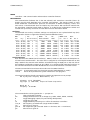
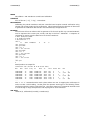
Oscillator
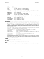
The dsPIC33f Fosc and Fcy oscillator settings are configured to use a phase-locked loop (PLL)
configuration chosen to support the following desired UART baud rates:
MHz
Fin
=====
8.00
8.00
8.00
8.00
8.00
8.00
8.00
8.00
8.00
Fcy
=====
36.89
36.89
36.89
36.89
36.89
36.89
36.89
36.89
36.89
|
|
|
|
|
|
|
|
|
|
|
|
PLL
| BAUD
LS
HS
| BRGH LS=0
Div Pre Post | Desired Real
Real
| LS
Err %
=== === ==== | ======= ======= ======= | ==== ======
164
7
0 |
9600
9606
9606 | 239 0.068
164
7
0 |
14400
14409
14409 | 159 0.068
164
7
0 |
19200
19212
19212 | 119 0.068
164
7
0 |
28800
28819
28819 |
79 0.068
164
7
0 |
38400
38425
38425 |
59 0.068
164
7
0 |
57600
57638
57638 |
39 0.068
164
7
0 | 115200 115277 115277 |
19 0.068
164
7
0 | 230400 230555 230555 |
9 0.068
164
7
0 | 256000 256172 256172 |
8 0.068
HS=1
HS
Err %
==== ======
959 0.068
639 0.068
479 0.068
319 0.068
239 0.068
159 0.068
79 0.068
39 0.068
35 0.068
Serial Interfaces
Each board has two UARTS (serial interfaces). UART1 is used as a bus across the backplane for
all inter-board communication. The serial line is configured as a full-duplex RS-485 bus at 256
Kbps. UART2 is the external serial interface accessible through an RJ45 port on the rear side of
the backplane configured to operate at 115.2 Kbps. It is configured with a RS-232 line driver on
the communication board and with RS-485 drivers on all of the transducer controller boards.
The AAL communication board uses two modes over the UART2 interface:
terminal/
linked
A command prompt (raw character terminal, default/power-on mode).
Serves 9P to provide a file system interface for user programs.
The terminal mode has simple command line interface and presents a user prompt:
AAL by Physical Property Measurements, Inc.
Firmware: 1.0.0 (20110330)
Copyright (c) 2010-2011, Corpus Callosum Corporation
Board ID: 0
Frequency: 36.89 MHz
>
The commands that can be typed at the ’> ’ prompt are:
?
Query the board id number.
bN
Change the baud rate to N, an integer (e.g. 9600, 19200, 38400, 115200).
D
Toggle debugging output (only used during development).
e
Toggle the error LED.
fb
Toggle feedback processing on or off for all transducer controllers.
freq N
Set frequency to N decihertz (range 221000-223000).
fN
Short form for ’freq N’.
gain N
Set output DAC gain (inverted: 3584 == minimum, 512 == maximum).
gN
Short form for ’gain N’.
39
CONTROLLERS(3)
m
mod P F
phase N
pN
P
reboot
reset
S
sN
tN cmd
v
CONTROLLERS(3)
Print measured values (see ’cat stats’ example below).
Transducer board only: set amplitude of modulation. A non-zero P and F turns mod
ulation on, otherwise off it is off. P is the percentage of amplitude change: -100 to
127. F is the frequency in Hz (e.g. 0.0 to >500.0) with 0.01 precision.
Transducer board only: change the DDS phase (0-4096 is equal to 0-360°)
Short form of ’phase N’.
Communication board only: toggle polling. Only used in testing as it turns data col
lection on and off.
Reboot the board.
Reset board(s) to default values. When invoked on the communication board, a
synchronized reset is sent to all boards.
Print board status details (see ’cat status’ file below).
Transducer board only: sensor board phase change command. Only executed when
the sensor feedback bit has been set.
Send 9P ctl command string to transducer board N (see AAL t N ctl definition
below).
Transducer board only: toggle fan.
The transducer boards by default do not use the external UART as a serial console. They are
configured to receive data from the AAL sensor(3). Setting feedback processing on will enable
the controllers to make phase adjustments based on the stream of data from the sensors. The
controllers will otherwise ignore all data received over the external serial interface.
The serial bus runs at 115.2Kbps for each sensor axis. The sensor head is the master node,
two transducer controller boards and an IOLAN interface port receive. Without a hardware
jumper the transducer controller boards will not be able to transmit data to the sensor head.
The sensor system sends a four-byte feedback packet 250 times a second:
0x73 s
0x?? signed 16-bit data representing degree phase change
0x??
0x0d ’\r’
On receiving a command from the sensor head the transducer control board changes the posi
tion phase. Both transducer boards will process the phase change within nanoseconds of each
other, producing the desired result for stabilizing the sample.
Adding a hardware jumper and enabling the transducer controller board debugging mode will
enable the external UART to provide a console interface for that board. In this debugging mode
the transducer board will operate similar to the communication board (without the 9P support).
Interface
The main board UART2 interface is also used for the GUI support which runs over a protocol
called 9p2000. It is started automatically by sniffing for a connection over the serial interface
or entering the command Styx to the main board from the ’> ’ prompt. Once the connection is
established, the end user’s application communicates with the main control board as a file sys
tem. The structure is a simple one level directory depicted here:
cpu% cd /n/aal
cpu% lc
ctl
status t1err t2err t3err t4err t5err t6err
data
t1
t2
t3
t4
t5
t6
stats t1ctl t2ctl t3ctl t4ctl t5ctl t6ctl
The files provide a running state of the system with read and write access. The t files are used
for each transducer control board, t1-t6. If the t files do not exist, then the control board is
either not installed in the backplane, or not responding to requests from the communication
board.
Each file is used to read and write specific information:
ctl
data
stats
status
Control file for sending commands.
Reading produces a packed byte version of the stats structure.
Transducer controller board statistics (described below).
Communication board status details.
40
CONTROLLERS(3)
CONTROLLERS(3)
tN
Transducer board statistics.
tNctl
Control file for individual transducer board.
Reading the statistics of all transducers is performed via:
cpu% cat stats
ID Ai Fi Phi Mper Mfreq Flags Vo PhiV Io PhiI F
t1 2000 221677 3756 0 0.00 65 2221 0 1654 3151 0
t2 2029 221677 2048 0 0.00 193 1982 0 1640 3275 0
t3 2400 221677 0 0 0.00 65 2439 0 1538 3212 1
t4 1655 221677 2048 0 0.00 193 2636 2938 1294 0
t5 2031 221677 0 0 0.00 65 2044 0 1691 3075 0
t6 1866 221677 2048 0 0.00 65 2372 0 1724 3295 1
The header row
ID
Ai
Fi
Phi
Mper Mfreq Flags Vo
PhiV Io
PhiI F
-
in the stats file represents each space-delimited entry:
transducer board id
output gain value set
output frequency
transducer phase on the axis
amplitude modulation percentage
amplitude modulation frequency in Hz
bit field flags of the transducer control board
Measured Voltage output
Voltage phase count
Measured Current output
Current phase count
Fan state (0 = off, 1 = on)
Turning the fans off for transducers 1 & 2 (X axis):
cpu% echo fan 0 > t1ctl
cpu% echo fan 0 > t2ctl
cpu% cat stats
ID Ai Fi Phi Mper Mfreq Flags Vo PhiV Io PhiI F
t1 3100 222000 0 0 0.00 132 507 2922 209 0 0
t2 3100 222000 2048 0 0.00 132 538 2892 265 0 0
...
Setting a new gain value for all transducers:
cpu% echo gain 2800 > ctl
cpu% cat stats
ID Ai Fi Phi Mper Mfreq Flags Vo PhiV Io PhiI F
t1 2800 222000 0 0 0.00 195 1034 0 589 3173 1
t2 2800 222000 2048 0 0.00 195 1467 3144 915 1
...
Setting the frequency:
cpu% echo freq 222000 > ctl
cpu% cat stats
ID Ai Fi Phi Mper Mfreq Flags Vo PhiV Io PhiI F
t1 2800 222000 0 0 0.00 193 1033 0 588 3187 1
t2 2800 222000 2048 0 0.00 193 1469 3133 913 1
...
Read the available commands for the main ctl file:
cpu% cat ctl
fb
freq
gain
haltstyx
reset
spin
41
CONTROLLERS(3)
CONTROLLERS(3)
Enable amplitude modulation on one transducer:
cpu% echo mod 20 11 > t1ctl
Read the main board configuration status:
cpu% cat status
Firmware: 1.0.0 (20100818)
Fosc: 73.78 MHz
Frequency: 36.89 MHz
PLL DIV/PRE/POST: 164
7
0
U1 BAUD: 256172.8 BRG:8
U2 BAUD: 115277.8 BRG:19
STKERR: 0
MATHERR: 0 DMAERR 0x0
U1 PERR: 0 FERR: 0
OERR: 0
U2 PERR: 0 FERR: 0
OERR: 2
Board ID: 0
Boards: id (online)
0: online
1: online
2: online
3: online
4: online
5: online
6: online
7:
The console(1) application uses the aforementioned file system to read status updates from the
Main board. It translates the transducer statistics into human readable values and facilitates
sending commands to the Main board.
Transducer bit field flags:
0 - feedback
-- process sensor feedback data
1 - tstep
-- sensed fast/slow switch
2 - tsfan
-- last state of sensed fan switch
3 - tfan
-- fan on/off indicator
4-6
reserved
7 - online
-- board on and responding over the backplane
/n/aal/ctl commands:
fb N
-- globally change sensor feedback processing: 0 = off, 1 = on
freq N
-- globally change transducer frequency
gain N
-- globally change transducer gain
reset
-- software reset, on sync all boards set default state values
spin S1 S2 N
-- spin change on a given axis
S1 is the string "X", "Y", or "Z" (case insensitive)
S2 is either "UP" or "DOWN" (case insensitive)
N is an 8-bit value of the phase change
/n/aal/t?ctl commands:
debug N -- Enables (1) or disables (0) debugging output over external UART.
fan N
-- turn fan on (1) or off (0)
fb N
-- turn sensor feedback processing on (1) or off (0)
freq N
-- set frequency to N (integer range only 220000 to 223000,
22.0 - 22.3 kHz)
gain N
-- set gain on DAC (inverted: 3584 == minimum, 512 == maximum)
mod N1 N2
-- set transducer amplitude modulation:
N1 -- fixed point percentage range from -100 to 127
N2 -- floating point value for frequency
phase N -- set phase, N is in range 0-4096 (0-360°)
reset
-- set default state values
sensitivity N -- set manual knob sensitivity, N is in range 0-255
42
CONTROLLERS(3)
CONTROLLERS(3)
e.g.: when N = 11, a knob click ~= 1°.
SOURCE
aal/sys/lib/aalcontrollers
SEE ALSO
console(1), phasedetector(3)
43
PHASEDETECTOR(3)
PHASEDETECTOR(3)
NAME
phasedetector – CPLD VHDL source for I-V phase detection
SYNOPSIS
entity PhaseDetector is
Port ( clk
reset
signal_a
signal_b
signal_x_out
signal_y_out
signal_a_div
:
:
:
:
:
:
:
in
in
in
in
out
out
out
STD_LOGIC;
STD_LOGIC;
STD_LOGIC;
STD_LOGIC;
STD_LOGIC;
STD_LOGIC;
STD_LOGIC);
end PhaseDetector;
DESCRIPTION
The phase detector is a modified shaft encoder implemented in the Xilinx CPLDs installed in the
transducer controller boards. It takes the voltage and current inputs and calculates the phase
difference for use in the dsPIC33F.
The three outputs are used to toggle gated timers and interrupt the dsPIC33F. The gated
timers provide a counter for the current and voltage. The interrupt handler in the controllers(3)
source code reads and resets the counter values. The resulting PhiI and PhiV values are used
in math(2) to calculate the phase difference in degrees.
SOURCE
aal/sys/lib/xilinx/CPLD/Slave/PhaseDetector.vhd
SEE ALSO
math(2), controllers(3)
44
SENSOR(3)
SENSOR(3)
NAME
sensor – AAL velocity feedback sensor
DESCRIPTION
The aalsensor33F firmware is installed on each of the sensor heads in the AAL. Its tasks are to
modulate an infrared laser (default at 40kHz), sample the resulting position through the Hama
matsu PSD, calculate velocity, and transmit a phase correction command over a serial line to a
pair of transducer controller.
The sensor interprets commands received over an EIA-485 serial line. The commands are:
Kd=N
Set the velocity gain to N/100.
debug=n
Turn debug mode on ’1’ or off ’0’.
fb=n
Enable ’1’ or disable ’0’ feedback transmission.
samp=n
Dump sampling data from PID function n times.
echostr
Echo str back over the serial line. The string is prefixed with a ’# ’.
dump
Dump data from PID function (debug=1).
halt
Stop sending debugging data dumps, debug=0.
noisecheck Dump 1000 PID results: Y[n], P, D, Vposy[n], Vref[n].
pscheck
Dump 32 PID results: Y[n], P, D, Vposy[n], Vref[n].
samp
Dump 250 PID results, P and D.
samp10
Dump 10 PID results, P and D.
samp100
Dump 100 PID results, P and D.
samp1000
Dump 1000 PID results, P and D.
samp12
Dump 12 PID results, P and D.
samp32
Dump 32 PID results, P and D.
samp1m
Dump 15000 PID results, one minute @ 250 per second, P and D.
stats
Print current state.
time
Run 1000 ADC sample sets (16 samples) without running the PID routine. The
calling application uses this to time routines on the sensor head.
timefb
Make 1000 PID calls before echoing back a result.
SOURCE
aal/sys/lib/aalsensor33F
SEE ALSO
controllers(3), sensors(1)
45
INTRO(4)
INTRO(4)
NAME
intro – introduction to file servers
DESCRIPTION
This section describes 9P services as used by the AAL. The file system presents a single level
tree as described in aal9p(4).
46
AAL9P(4)
AAL9P(4)
NAME
aal9p – distributed aero-acoustic levitator file system
SYNOPSIS
mount -A [ -S ] aaladdr dir
ctl
data
stats
status t1err
t1
t2
t1ctl t2ctl
t2err
t3
t3ctl
t3err
t4
t4ctl
t4err
t5
t5ctl
t5err
t6
t6ctl
t6err
DESCRIPTION
The AAL9P file system provides distributed access to the AAL using the 9P protocol. It provides
ctl files for sending parameter changes to the device and reading data stored in the communi
cation node of the system. Individual transducer controller statistics and settings can be
accessed through the t[1-6] files.
The namespace is accessed by mounting the service at the address aaladdr on the desired
directory dir. The aal9p service requires the use of the -A option as there is no authentication
provided by the device. The default address is tcp!iolan!aal9p and is mounted by convention at
/n/aal.
Client interface
Commands controlling the state of the AAL are written to the ctl files. The client reads the
AAL state through the data, stats, status or t? files.
Control commands
Global changes of frequency, gain, or cooling fan state are accomplished through writing a
command and one or more parameters to the ctl file.
fan n
fb n
freq dhz
gain k
Turns the fans on ’1’ or off ’0’.
Enables ’1’ or disables ’0’ velocity feedback processing.
Sets the operating frequency to dHz. Valid ranges are 220000 to 223000 .
Set all transducer preamp output to the gain value k. The inverted range is 3584
for zero output and 512 for the maximum board output.
gains 6k
Set each transducer to the output gain value associated with the parameter. Six
gain arguments are required.
reset
Set all transducers to zero output and restore default phase and spin values.
spin axis up|down n
Set the axis spin settings up or down to n phase.
spl n
Store the target SPL value to n.
The transducer t?ctl files are used for individual control:
debug n
Enable ’1’ or disable ’0’ debugging output over UART2.
fan n
Turns the fan on ’1’ or off ’0’.
fb n
Enables ’1’ or disables ’0’ velocity feedback processing.
freq dhz
Sets the operating frequency to dHz. Valid ranges are 220000 to 223000 .
gain k
Set transducer preamp output to the gain value k. The inverted range is 3584 for
zero output and 512 for the maximum board output.
mod per hz
Set amplitude modulation to percent and Hz.
phase n
Set the phase 0-4096.
reset
Set transducer to zero output and restore default phase and spin values.
SOURCE
aal/sys/lib/aalcontrollers
47
INTRO(5)
INTRO(5)
NAME
intro – introduction to file formats and system conventions
DESCRIPTION
There are various file formats used throughout the AAL system. The Limbo programs
console(1), pyro(1), and sensors(1) use an s-expression format for their configuration files. Log
files generated by AAL programs are human readable and easily parsed with awk and other
common utilities.
SEE ALSO
http://en.wikipedia.org/wiki/S-expression
http://www.vitanuova.com/inferno/man/2/sexprs.html
48
CONSOLE(5)
CONSOLE(5)
NAME
console – log file format from the console
DESCRIPTION
The console(1) logs data to the $home/logs/aal/console directory. A new file is created on pro
gram start using date-time format yyyymmdd_HHMMSS.log. The log is appended every ten sec
onds with statistics for each transducer. User events changing the SPL, velocity feedback, and
tracking state changes are added as they occur. Header details at the start of the log are com
mented using an unquoted # character.
The tab-delimited columns for transducer statistics are:
Time
Bid
Gain
Freq
Phase
Mper
Mfreq
Vo
PhiV
Io
PhiI
Fan
Vi
Ii
Phic
Phi
P
SPL
Vc
RFreq
The number of seconds since the epoch, 00:00:00 GMT, January 1, 1970.
The board identifier: t1-t6.
DAC output gain setting.
The operating frequency in kHz.
The integer representation of the phase degrees, 0-4096 = 0-360°.
Amplitude modulation percentage.
Amplitude modulation frequency.
Voltage output measured by the ADC.
Integer counter of the Voltage phase.
Current output measured by the ADC.
Integer counter of the Current phase.
The transducer fan on/off state.
Calculated voltage.
Calculated current.
Calculated I-V phase difference.
Calculated true I-V phase difference.
Calculated amplifier power.
Calculated SPL output.
Calculated gain voltage.
Calculated resonant frequency of the transducer.
SPL changes initiated by the user are logged on a single line. The second and third columns
are "Set SPL:" followed by a series of transducer gain changes, e.g.: (t1: (1688, 1528)) . The
string is a valid s-expression with the key ’t1’ representing transducer XA. The following two
numbers represent the operating gain followed by the new gain required to achieve the new
SPL.
Sensor feedback changes are logged as "Sensor feedback: 1" with a ’1’ turning velocity feed
back processing on and a ’0’ when the feedback has been turned off.
User changes to resonant frequency and SPL tracking are logged with a "Track" element in the
second column.
EXAMPLE
Grap is used to process the console(1) log file. This example depicts the resonant frequency
tracking of the system during the course of an experiment. The spread between the resonant
frequencies of the transducers is presented as a numeric value in Hz at regular intervals.
49
CONSOLE(5)
CONSOLE(5)
30.6
22.2
27.4
24
·
20.8
·
23.4
·
22.15
XA
XB
YA
YB
ZA
ZB
7.9
7.1
24.6
·
7.9
19.8
·
20.4
·
14.5
·
22
·
·
·
9.4
·
·
·
·
22.1
.2
.8
fb 1
1
.8
.7 .75
||
|
||
|
| |
0
2500
5000
7500
10000
Time in seconds
FILES
$home/logs/aal/console/*.log
aal/sys/src/aal/man/data/console5.g
SEE ALSO
console(1)
50
.749
| |
12500
||
|
15000
PYRO(5)
PYRO(5)
NAME
pyro – definition of the pyro.cfg configuration file
SYNOPSIS
(date "Fri Apr 29 17:18:38 CDT 2011")
(x "37479")
(y "37125")
(swidth "4.5")
(sheight "4.5")
DESCRIPTION
The pyro(1) configuration file stores the Zaber microstep X and Y positions, and scan width and
height values in millimeters. The file can be edited in any text editor though it is easiest to save
changes from the pyro(1) application as needed.
FILES
~/lib/pyro.cfg
SEE ALSO
pyro(1), zaber(2)
51
SENSORS(5)
SENSORS(5)
NAME
sensors – definition of the sensor.cfg configuration file
SYNOPSIS
(date "Tue Mar 29 17:15:17 CDT 2011")
(X (sensitivity ".00234562"))
(Y (sensitivity ".00231741"))
(Z (sensitivity ".00200134"))
DESCRIPTION
The sensor.cfg file stores slope sensitivity values used in calculating the digital gain applied on
each sensor head. The data used to populate the values is generated using the pscheck(1)
program and additional grap files. The file is saved directly from the sensors(1) application.
FILES
~/lib/sensor.cfg
SEE ALSO
pscheck(1), sensors(1)
52
TEMPERASURE-BIN(5)
TEMPERASURE-BIN(5)
NAME
temperasure – TemperaSure binary data storage format
DESCRIPTION
The Exactus files created when the pyro(1) application is logging data are in the TemperaSure
binary format. This format was used as the model for the Exactus Trecord type. Each data
object in the record is stored as a 32-bit little endian value.
The timestamp is a 32-bit unsigned integer representing the milliseconds since the first record
in the data set. All timestamps are approximate due to communication and processing latency.
All the remaining data objects are 32-bit IEEE-734 floating point numbers. The exactus(2)
Trecord->pack() and Trecord->unpack() functions handle conversion from IEEE-734 to Limbo
data types.
EXAMPLE
Dumpbin(1) can be used to generated a text file usable by grap to generate a graph of temper
ature data. The following graph shows two recalescence events triggered by turning off the
heating lasers for approximately three seconds before turning them back on (just after 175s
and 185s). The sample is reheated in-between the two events.
2500
2000
Celsius
1500
170
175
180
Time in seconds
185
The data is processed using this simple grap script:
.de CL
\X’PS \$1 \$2 \$3 setrgbcolor’\c
..
.de BK
\X’PS 0 0 0 setrgbcolor’\c
..
.G1 6.0
graph Temperature
frame ht 1.6 wid 6.0
draw px solid
start = 170000
stop = 187500
.CL 1 0 0
copy "x-20110331_180657.txt" thru {
if "$1" == "#" then {} else {
if start <= $1 && $1 <= stop then { next px at ($1/1000, $2) }
}
}
.BK
label bottom "Time in seconds"
label left "Degrees" "Celsius" left .45
.G2
FILES
~/logs/aal/exactus/*.bin
SEE ALSO
dumpbin(1), exactus(2), pyroplot(2), temperasure-dat(5)
53
TEMPERASURE-DAT(5)
TEMPERASURE-DAT(5)
NAME
temperasure-dat – TemperaSure header file format
DESCRIPTION
The .dat file is generated by pyroplot(2) when closing the log file. It is used by the Tempera
Sure software to open the binary storage file. The file should stay in the same directory as the
similarly named .bin file.
A subset of the entries stored in the file are:
name
count
serial
startTime
msPerPoint
A reference path to the binary data file this file will open.
The number of Trecord data objets stored in the content file.
The Exactus serial number used to create this content file.
The date and time when the log file started.
The millisecond division between points.
FILES
~/logs/aal/exactus/*.dat
SEE ALSO
exactus(2), pyroplot(2), temperasure-bin(5)
54
TRANSDUCER(5)
TRANSDUCER(5)
NAME
transducer – definition of the transducer.cfg configuration file
SYNOPSIS
(date "Mon Mar 21 16:34:02 CDT 2011")
(IVPc "7.378E+07")
(t1 (sn "12") (tsn "10A") (Av "0.004934") (Ai "0.3641")
(Aspl "0.11320") (Ag "-1.4160") (Bg "4916.7")
(A1 "0.4526") (A0 "-7.121"))
(t2 (sn "14") (tsn "1B") (Av "0.004884") (Ai "0.3610")
(Aspl "0.09092") (Ag "-1.4118") (Bg "4967.8")
(A1 "0.4754") (A0 "-6.760"))
(t3 (sn "18") (tsn "2A") (Av "0.004902") (Ai "0.3627")
(Aspl "0.11121") (Ag "-1.4102") (Bg "5009.1")
(A1 "0.5050") (A0 "-8.613"))
(t4 (sn "16") (tsn "3A") (Av "0.004859") (Ai "0.3637")
(Aspl "0.11202") (Ag "-1.4096") (Bg "4939.0")
(A1 "0.4615") (A0 "-6.213"))
(t5 (sn "17") (tsn "2B") (Av "0.004980") (Ai "0.3641")
(Aspl "0.11335") (Ag "-1.4117") (Bg "4981.1")
(A1 "0.4603") (A0 "-6.255"))
(t6 (sn "15") (tsn "X3") (Av "0.004876") (Ai "0.3611")
(Aspl "0.12008") (Ag "-1.4188") (Bg "4956.2")
(A1 "0.4334") (A0 "-5.949"))
DESCRIPTION
The calibration parameters for each transducer and transducer controller board pair are stored
in the transducer.cfg file. This file is an s-expression format and is read using functions in the
sexprs module.
A record entry for each transducer is in the file. The numbering goes from t1 for XA to t6 for
the ZB transducer controller.
FILES
~/lib/transducer.cfg
SEE ALSO
calibration(2), math(2)
55
INTRO(6)
INTRO(6)
NAME
intro – introduction to administration modules and system services
DESCRIPTION
This section of the manual covers the tools used to administer and calibrate the AAL. Many of
these examples are directly related to the intro(1) commands.
Items not covered in prior sections are details on the Inferno and IOLAN administration files that
facilitate the system. Iolan(6) describes the configuration of the IOLAN device server to sup
port the eight serial devices connected throughout the system. The ndb(6) reference details
network databases used by the Inferno programs to look up the services provided by the AAL.
SEE ALSO
calibtran(6), iolan(6), ndb(6), pscheck(6), scanfreq(6)
56
CALIBTRAN(6)
CALIBTRAN(6)
NAME
aal/calibtran – AAL transducer control board calibration
SYNOPSIS
aal/calibtran [ -d ] [ -l log ] -t transducer
DESCRIPTION
Calibrating the paired transducer and AAL controller board requires manual verification using
voltage and current probes and an oscilloscope. This program eases the collection of data used
to generate the calibration data stored in the transducer(5) configuration file.
EXAMPLE
The end user will use an Inferno shell to generate a file for each profile. By convention DATE is
used to represent the current year, month, and day in the form ’20110310’. A sequence of
commands is used to save the data into a file for the transducer:
% mkdir $home/tests/DATE
% cd $home/tests/DATE
% aal/calibtran -t 2
cmd: m
t1
3584
222000 91
cmd: freq 22.2
cmd: gain 3000
cmd: s 1 1 1
cmd: s -0.4 3.52 170
cmd: gain 2600
cmd: s 1 1 1
cmd: s -0.6 6.28 304
cmd: gain 2200
cmd: s 1 1 1
cmd: s -0.9 9.2 436
...
cmd: quit
%
0
78
0
Would produce an output file:
Calibration scan (Thu Mar 10 11:31:01 CST 2011)
Now
Bid
Gain
Freq
Vo
PhiV
Io
PhiI
1299778588
1299778604
1299778626
1299778646
1299778667
1299778684
...
t2
t2
t2
t2
t2
t2
3000
3000
2600
2600
2200
2200
222000
222000
222000
222000
222000
222000
732
732
1298
1282
1862
1862
3196
3197
3196
3184
3169
3150
487
489
851
843
1196
1183
Delta
PkV
PkI
0
0
0
0
0
0
1
-.4
1
-.6
1
-.9
1
3.52
1
6.28
1
9.2
1
170
1
304
1
436
The ’s 1 1 1’ command entries mark a place where one user is stopping the oscilloscope in
order to make a valid reading. At that point the operator would type in the following values
read back and hit the return to finish the line. The same sequence of commands would be used
to scan through a range of frequencies and output gain for each transducer.
SEE ALSO
calibtran(1), calibration(2) math(2), transducer(5)
57
IOLAN(6)
IOLAN(6)
NAME
iolan – IOLAN administration
DESCRIPTION
The IOLAN device server enables the access of serial devices over an Ethernet network. The
AAL uses this server to bridge between the various RS-232 and RS-485 serial devices used in
controlling the system.
IOLAN administration takes place through a web or shell interface. It has been configured to
provide the following port mappings:
10001
10002
10003
10004
10005
10006
10007
10008
RS-232
RS-232
RS-232
RS-232
RS-485
RS-485
RS-485
RS-232
port,
port,
port,
port,
port,
port,
port,
port,
9600 bps, connected to a Synrad UC-2000 controller.
9600 bps, connect to a Synrad UC-2000 controller.
115200 bps, connected to the Exactus pyrometer.
9600 bps, connected to the Zaber XY translators.
115200 bps, connected to sensor head X.
115200 bps, connected to sensor head Y.
115200 bps, connected to sensor head Z.
115200 bps, connected to the AAL communications controller.
The ports are configured to use a raw line service application, inraw, running on the IOLAN. A
TCP connection opens the corresponding serial port and tunnels raw bytes to and from the
serial device. A modified inraw_aal application is used for the AAL communications controller
port. The inraw_aal messages the AAL communication controller with a special command
sequence when the TCP port has been closed.
FILES
aal/sys/src/iolan/IOLAN-103CCB-config.txt
aal/sys/src/iolan/inraw.c
aal/sys/src/iolan/inraw_aal.c
SEE ALSO
http://www.perle.com/products/documentation.asp?a=3&i=47
58
NDB(6)
NDB(6)
NAME
ndb – network data base
SYNOPSIS
/lib/ndb/aal
DESCRIPTION
The AAL network configuration is added to the Inferno supplied /lib/ndb/local data base.
Keeping this file as a single configuration for AAL specific network services eases the adminis
tration if an Internet address needs to be modified. The added TCP services map to the ports
on the IOLAN device server. The system name iolan is mapped to provide a simple lookup con
trolled by the AAL system.
EXAMPLE
#
# AAL port assignments
#
tcp=aal9p port=10008
tcp=sensorz port=10007
tcp=sensory port=10006
tcp=sensorx port=10005
# AAL Host 9p service
# AAL Sensor connection ports
tcp=zaber port=10004
tcp=exactus port=10003
tcp=synradtwo port=10002
tcp=synradone port=10001
#
# AAL Hosts
#
ipnet=aalnet ip=192.168.1.1 ipmask=/24
ip=192.168.1.8 sys=iolan
ip=192.168.1.10 sys=lenovo
FILES
/lib/ndb/*
SEE ALSO
Inferno ndb configuration.
59
PSCHECK(6)
PSCHECK(6)
NAME
pscheck – sensor position sensitivity check
SYNOPSIS
aal/sensor/pscheck [ -a ] [ -d ] [ -r ±range ] [ -s spl ] [ -t ] [ -v ] [ -Y ] [ axis ]
DESCRIPTION
The pscheck program is used to verify the sensor alignment using a polystyrene bead. Nine
data files corresponding to the axis of sample translation and sensor collection will be created
in the current working directory.
Pscheck needs full control over the AAL device to complete the sample check. The user must
not be running the console(1) or sensors(1) during the experiment. The program is run from
the Inferno shell:
% mkdir $home/tests/DATE
% cd $home/tests/DATE
% aal/sensor/pscheck -a -r 200 -Y
..
The resulting data files are used by a grap program run from a Linux shell to create output files.
The plot of the slope and sensitivity values can then be entered directly into the sensors(1)
application to calibrate the sensor feedback gain.
The Linux shell commands have examples in ~/tests. In order to use those scripts it is usual
to:
% cd ~/tests/DATE
% ln -s ../scripts/* .
% 9 mk pdf
The ln command links all of the files from the scripts directory into the local directory. The user
then executes the command ’9 mk pdf’ to generate the output files in the local directory. The
final output is saved in PostScript and PDF files.
FILES
$home/tests/scripts/pscheck.g
$home/tests/scripts/pscheckfit.g
SEE ALSO
pscheck(1),
Two example pages follow.
60
PSCHECK(6)
PSCHECK(6)
Alignment tests.
1.2
1
0.8
æ
æ
æ
0.6
æ
æ
æ
ææææ
æ
æ
ææ
æ
ææ
ææææ
æææ
æææææ
æ
æ
æ
ææææææ
ææææææ
ææææ
æ
æ
æ
æææææ
æ
Range 0.786
ææææ
æ
æ
æ
æ
ææ
æ
æ
æ
æ
∆∆∆ ∆
∆∆
∆
∆∆∆∆∆∆∆∆∆
∆∆∆ ∆∆∆ ∆
∆ ∆
∆∆∆ ∆∆
∆∆ ∆∆∆∆∆ ∆
∆∆∆∆ ∆∆
∆∆ ∆
–100
0
100
200
Fig 1. X Position vs Phase
–200
1
0.8
æ
æ
æ
æ
0.4
æ
æææ
æ
æ
æ
æ
æ
æ
ææææ
ææææ
ææææææ
æ
æ
æææ
ææææ
ææææ
æææææ
æ
æ
æææææ
ææ
æ
Range 0.626
æææ
æ
æ
æ
æ
æ
æ
æ
æ
æ
æ
0.8
æ
æ
æ
æ
æ
0.4
–200
ææææ
ææ
ææ
æ
æ
ææ
æææææ
æææææ
æææ
æ
æ
æ
æ
æ
æææ
æææ
ææææææ
æææææ
æ
æ
ææ
æ
æ
∆ ∆∆
∆∆∆∆ ∆
æ
æææ
æ
æ
æ
æ
æææææææ
æ
ææ ææ
æææ æ ææ
ææ
æææ
æææææ ææææææææææææ æ
æ
æææ æ æ æ æ
æ
æ
æ æ
∆∆ ∆
∆ ∆ ∆∆
∆
∆ ∆ ∆ ∆∆∆ ∆∆∆∆∆∆∆∆∆∆∆∆∆∆∆∆∆∆∆∆ ∆ ∆ ∆
∆ ∆∆ ∆ ∆∆∆∆∆
∆
∆ ∆∆∆∆ ∆
∆
∆ ∆∆ ∆∆ ∆
∆∆
¡ ¡¡ ¡
¡ ¡
¡
¡
¡¡
¡ ¡¡
¡
¡
¡¡ ¡¡¡¡
¡¡
¡¡¡¡¡
¡¡¡
¡
¡
¡ ¡¡
¡
¡ ¡
¡
¡
¡
¡
¡
¡
¡ ¡ ¡¡
æ
¡
¡¡¡
¡
æ
æ
¡
æ ¡
¡¡æ
æ æ
æ
æ
æ
æ æ¡¡
æ¡
æ¡
æ
¡¡æ
æ
¡
ææ
¡
æ æ
¡
æ
æ
¡
æ
¡
æ
æ
æ
æ
æ æ
¡
ææ
æ
æ
æ
æ æ æ ææ
æ ææææææ
¡
ææ æ æ
æ æææææææ ææææ
æææææææ
æ
Vy min (1634), max (4100)
Vr min (3392), max (4544)
Avg: 0.00265154
X slope 0.00298323
X rs 1.1251
X gain 0.888813
∆∆ ∆ ∆
∆ ∆
0.65
0.75
0.7
–200
–100
0
100
200
Fig 4. X (circle) and Z (delta) Position vs Phase
Range 0.663
æ ææ æ æ
æ
ææ
æ
æ
æ
æ
æ
æ
–100
0
100
200
Fig 5. Z Position vs Phase
0.7
0.8
æ æ
æ æ
Vy min (1643), max (4029)
Vr min (3430), max (4349)
1
0.6
ææææææ
–100
0
100
200
Fig 3. Y Position vs Phase
–200
0.75
–200
–100
0
100
200
Fig 2. Y (square) and Z (delta) Position vs Phase
∆
∆ ∆ ∆ ∆∆ ∆ ∆ ∆
æ
0.8
∆
∆∆ ∆∆ ∆ ∆ ∆
∆ ∆
Vy min (1642), max (4329)
Vr min (3221), max (4247)
0.4
0.6
¡
¡
¡ ¡¡
¡
¡
¡
¡ ¡ ¡¡
¡
¡ ¡
¡
¡¡
¡
¡
¡
¡
¡ ¡ ¡
¡
¡
¡
¡
¡
¡
¡
¡
¡
¡¡
¡
¡
¡
¡
¡
¡
¡
¡
¡
¡¡¡¡¡
¡
¡
¡
¡¡¡
¡¡
¡
¡¡
¡
¡
¡¡
¡
¡
¡
¡
¡¡
0.8
0.78
0.76
0.74
–200
–100
0
100
200
Fig 6. X (circle) and Y (square) Position vs Phase
Y slope 0.00250751
Y rs 0.945682
Y gain 1.05744
61
Z slope 0.00246387
Z rs 0.929222
Z gain 1.07617
PSCHECK(6)
PSCHECK(6)
Alignment tests.
X
0.4
Z
.
..
..
..
.
..
.
. .. .
.. .. .. .
.
.
.
...
.. ....
.. .....
.
. ....
.. ....
.. .....
.
. ...
.. .....
.. .....
.
..
......
......
.
.
.
. ..
......
.......
.
.
.
......
...
...
.. ..
...
.....
.....
.
.
...
... .
.....
.....
.
.
..
... .
... .
... ...
.
.
.. .
... .
... .
... ...
.
.
.. .
... .
... .
... ...
.
.
.
... ..
... ..
...
.
.
..
..
... ...
...
.
.
.
.
..
.. .
..
.. ..
..
.
.
..
..
.
.
0.2
0
–0.2
Y
–0.4
–200
0
Fig 1.
–100
Avg: 0.00265154
X slope 0.00298323
X rs 1.1251
X gain 0.888813
Y slope 0.00250751
Y rs 0.945682
Y gain 1.05744
62
100
200
Z slope 0.00246387
Z rs 0.929222
Z gain 1.07617
SCANFREQ(6)
SCANFREQ(6)
NAME
aal/scanfreq – acoustic frequency scanner
SYNOPSIS
aal/scanfreq [ -d ] [ -g gain ] [ -l low kHz ] [ -h high kHz ] [ -m ms ]
DESCRIPTION
Scanfreq is a simple program that collects voltage, current, and V-I phase data from the trans
ducer control boards.
EXAMPLE
Frequency scan (Tue Mar 22 22:39:36 GMT 2011)
Gain=1000
22.12kHz to 22.24kHz
Delay: 500 ms
Seq
Bid
Gain
0
0
0
0
0
0
1
1
1
1
1
1
...
t1
t2
t3
t4
t5
t6
t1
t2
t3
t4
t5
t6
1000
1000
1000
1000
1000
1000
1000
1000
1000
1000
1000
1000
Freq
Vo
PhiV
Io
PhiI
222400
222400
222400
222400
222400
222400
222380
222380
222380
222380
222380
222380
3542
3557
3580
3572
3637
3490
3541
3557
3581
3571
3639
3489
0
2917
3188
3214
2614
2785
0
2844
3118
3130
2579
2741
210
246
249
178
292
280
213
263
263
184
313
298
3091
0
0
0
0
0
3196
0
0
0
0
0
SEE ALSO
scanfreq(1)
63
INDEX
Manual pages for all sections are accessible on line through man(1). The affliated manual
page will need the prefix ’aal-’ in order to be found on the Inferno manual.
intro – introduction
calibration . . . . . . . . . . . . . . . . . . . . . . . . . .
capture . . . . . . . . . . . . . . . . . . . . . . . . . . . . .
console . . . . . . . . . . . . . . . . . . . . . . . . . . . . .
dumpbin . . . . . . . . . . . . . . . . . . . . . . . . . . . .
noisecheck . . . . . . . . . . . . . . . . . . . . . . . . . .
pscheck . . . . . . . . . . . . . . . . . . . . . . . . . . . .
pyro . . . . . . . . . . . . . . . . . . . . . . . . . . . . . . .
scanfreq . . . . . . . . . . . . . . . . . . . . . . . . . . . .
sensors . . . . . . . . . . . . . . . . . . . . . . . . . . . . .
sim . . . . . . . . . . . . . . . . . . . . . . . . . . . . . . . .
timing . . . . . . . . . . . . . . . . . . . . . . . . . . . . . .
uc2k . . . . . . . . . . . . . . . . . . . . . . . . . . . . . . .
intro – introduction to Limbo modules
calibration . . . . . . . . . . . . . . . . . . . . . . . . . .
common . . . . . . . . . . . . . . . . . . . . . . . . . . . .
exactus . . . . . . . . . . . . . . . . . . . . . . . . . . . .
math . . . . . . . . . . . . . . . . . . . . . . . . . . . . . .
modbus .
pyroplot .
scope . . .
sensorplot
stats . . . .
timedio . .
uc2000 . .
. . . .
. . . .
. . . .
. . .
. . . .
. . . .
. . . .
.
.
.
.
.
.
.
.
.
.
.
.
.
.
.
.
.
.
.
.
.
.
.
.
.
.
.
.
.
.
.
.
.
.
.
.
.
.
.
.
.
.
.
.
.
.
.
.
.
.
.
.
.
.
.
.
.
.
.
.
.
.
.
.
.
.
.
.
.
.
.
.
.
.
.
.
.
.
.
.
.
.
.
.
.
.
.
.
.
.
.
.
.
.
.
.
.
.
.
.
.
.
.
.
.
.
.
.
.
.
.
.
util . . . . . . . . . . . . . . . . . . . . . . . . .
zaber . . . . . . . . . . . . . . . . . . . . . . .
intro – introduction to
aalcall . . . . . . . . . . . . . . . . . . . . . .
controllers
.
.
.
.
.
.
.
.
.
.
.
.
.
.
.
.
.
.
.
.
.
.
.
.
.
.
.
.
.
.
.
.
.
.
.
.
.
.
.
.
.
.
.
.
.
.
.
.
.
. . . . . . .
. . . . . . .
firmware
. . . . . . .
. . . . . . . . . . . . . . . . . . . . . . . . . .
phasedetector . . . . . . . . . . . . . . . . . . . . . . .
sensor . . . . . . . . . . . . . . . . . . . . . . . . . . . . .
intro – introduction to file servers
aal9p . . . . . . . . . . . . . . . . . . . . . . . . . . . . . .
intro – introduction to file formats
and system convensions
console . . . . . . . . . . . . . . . . . . . . . . . . . . . . .
pyro . . . . . . . . . . . . . . . . . . . . . . . . . . . . . . .
sensors . . . . . . . . . . . . . . . . . . . . . . . . . . . . .
temperasure-bin . . . . . . . . . . . . . . . . . . . . . .
temperasure-dat . . . . . . . . . . . . . . . . . . . . . .
transducer . . . . . . . . . . . . . . . . . . . . . . . . . .
intro – introduction to administration
modules and system services
calibtran . . . . . . . . . . . . . . . . . . . . . . . . . . . .
iolan . . . . . . . . . . . . . . . . . . . . . . . . . . . . . . .
ndb . . . . . . . . . . . . . . . . . . . . . . . . . . . . . . . .
pscheck . . . . . . . . . . . . . . . . . . . . . . . . . . . .
scanfreq . . . . . . . . . . . . . . . . . . . . . . . . . . . .
to the Aero-Acoustic Levitator . . . . . . . . . . . .
intro(1)
transducer control board calibration . . . . . . .
calibtran(1)
sensor phase data capture . . . . . . . . . . . . . .
capture(1)
a graphical AAL console . . . . . . . . . . . . . . . .
console(1)
dump TemperaSure file contents . . . . . . . . .
dumpbin(1)
sensor detector noise check . . . . . . . . . . . . . noisecheck(1)
sensor position sensitivity check . . . . . . . . . .
pscheck(1)
graphical pyrometer robotic positioning tool .
pyro(1)
acoustic frequency scanner . . . . . . . . . . . . . .
scanfreq(1)
graphical feedback sensor tool . . . . . . . . . . .
sensors(1)
sensor output simulator . . . . . . . . . . . . . . . .
sim(1)
sensor timing test tool . . . . . . . . . . . . . . . . .
timing(1)
graphical Synrad laser controller interface . .
uc2k(1)
specific to the AAL . . . . . . . . . . . . . . . . . . . .
intro(2)
AAL calibration parameters . . . . . . . . . . . . . . calibration(2)
AAL common module . . . . . . . . . . . . . . . . . .
common(2)
Exactus pyrometer interface . . . . . . . . . . . . .
exactus(2)
floating point resonant frequency . . . . . . . . .
. . . . . . . . . . . . . . . . . . . . and SPL functions
math(2)
Modbus protocol . . . . . . . . . . . . . . . . . . . . . .
modbus(2)
graphical plotting of Exactus measurements .
pyro(2)
graphical representation of AAL acoustics . . .
scope(2)
graphical sensor feedback plot . . . . . . . . . . . sensorplot(2)
graphical window displaying AAL statistics . .
stats(2)
timeout functions for I/O and dial . . . . . . . . .
timedio(2)
support module for interfacing . . . . . . . . . . .
Synrad UC-2000 laser controllers . . . . . . . . .
uc2000(2)
common utility functions . . . . . . . . . . . . . . . .
util(2)
interface to Zaber Technologies linear stages
zaber(2)
. . . . . . . . . . . . . . . . . . . . . . . . . . . . . . . . . .
intro(3)
interface AAL controller-to-controller . . . . . . .
communication protocol . . . . . . . . . . . . . . . .
aalcall(3)
AAL communication and transducer . . . . . . .
controller firmware . . . . . . . . . . . . . . . . . . . . controllers(3)
CPLD VHDL source for I-V phase detection .phasedetector(3)
.
AAL velocity feedback sensor . . . . . . . . . . . .
sensor(3)
. . . . . . . . . . . . . . . . . . . . . . . . . . . . . . . . . .
intro(4)
distributed aero-acoustic levitator file system
aal9p(3)
. . . . . . . . . . . . . . . . . . . . . . . . . . . . . . . . . .
. . . . . . . . . . . . . . . . . . . . . . . . . . . . . . . . . .
intro(5)
log file format from the console . . . . . . . . . .
console(5)
definition of the pyro configuration file . . . . .
pyro(5)
sefinition of the sensor configuration file . . . .
sensors(5)
TemperaSure binary data storage format temperasure-bin(5)
. . .
TemperaSure header file format . . . . . . .temperasure-dat(5)
. . .
definition of the transducer configuration file . transducer(5)
. . . . . . . . . . . . . . . . . . . . . . . . . . . . . . . . . .
. . . . . . . . . . . . . . . . . . . . . . . . . . . . . . . . . .
intro(6)
AAL transducer control board calibration . . . .
calibtran(6)
IOLAN administration . . . . . . . . . . . . . . . . . .
iolan(6)
network database . . . . . . . . . . . . . . . . . . . . .
ndb(6)
sensor position sensitivity check . . . . . . . . . .
pscheck(6)
acoustic frequency scanner . . . . . . . . . . . . . .
scanfreq(6)
1
2
3
4
6
7
8
9
10
11
12
13
14
15
16
17
19
22
23
27
29
30
31
32
33
35
36
37
38
39
44
45
46
47
48
49
51
52
53
54
55
56
57
58
59
60
63
1-i
This manual was typeset in DejaVu Sans by the
authors using the Plan 9 version of troff:
troff | tr2post | psfonts > print.ps
The input text was characters from the Unicode
Standard encoded in UTF-8.
DejaVu Sans is Copyright © 2003 by Bitstream,
Inc. All Rights Reserved.