1
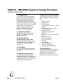
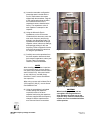
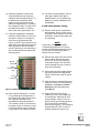
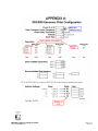
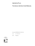
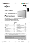
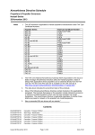
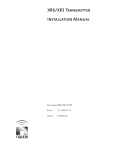
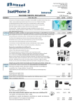
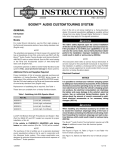
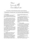
XR3/XR6
Frequency Change
Procedure
IS07012
Issue 1.0 ................10 September 2007
Nautel Limited
10089 Peggy's Cove Road,
Hackett's Cove, NS, Canada B3Z 3J4
T.877 6 nautel (628835) or +1.902.823.2233
F.+1.902.823.3183 [email protected]
U.S. customers please contact:
Nautel Inc.
201 Target Industrial Circle, Bangor ME 04401
T.877 6 nautel (628835) or +1.207.947.8200
F.+1.207.947.3693 [email protected]
e-mail: [email protected]
www.nautel.com
© Copyright 2007 NAUTEL. All rights reserved.
IS07012 – XR3/XR6 Frequency Change Procedure
INFORMATION SHEET
1 INTRODUCTION
The XR3/XR6 is basically a broadband
amplifier with fixed tuned elements in the
RF drive stage and the RF output filter.
The selection of frequency sensitive
components and adjustment of variable
inductors used in these circuits is normally
performed at the factory at the transmitter’s
assigned carrier frequency. When a
frequency change is required, use the
following procedures to realign the
frequency sensitive components.
1.1 Equipment Affected
This procedure applies to first release
XR3/XR6 transmitters (Nautel Part #
NARA48 and NARA49).
1.2 Responsibility for
Implementation of Procedure
This procedure should be carried out by
qualified station maintenance personnel
who are familiar with the XR3/XR6
transmitter.
1.3 Scheduling
This procedure may be implemented at
the convenience of station maintenance
personnel.
1.4 Manpower Requirements
It is estimated that implementing this
modification will require eight (8) hours to
complete. Note that it is necessary for the
transmitter to be placed in an off-air status
for the duration of this procedure.
XR3/XR6 Frequency Change Procedure
IS07012
1.5 Special Tools/Test Equipment
The following test equipment is required.
Where applicable, items are referenced in
text.
•
•
•
•
•
•
•
•
•
•
•
•
•
•
•
•
•
Spectrum analyzer
Oscilloscope
Digital multimeter
Vector impedance meter (e.g., Tomco
TE1000)
Function generator (audio to RF)
Frequency counter
Modulation monitor
Audio test set (response and
distortion)
RF Current Probe(or Delta probe with
meter)
RMS voltage meter
Delta RF current probe
200 Ω potentiometer
Notch filter
Attenuator pad
Test cable (202-5010)
Test load (176-5720-01)
Computer with Microsoft® Excel®
1.6 Parts Required
The frequency dependent parts required
to change to the new frequency were
shipped in the same package as this
document. Part contents will vary
depending on the new carrier frequency.
Page 1 of 7
Issue 1.0
2 INSTRUCTIONS
The frequency change procedure
comprises four main steps:
•
•
•
•
RF frequency change (see 2.1)
Output filter tuning (see 2.2)
RF power module tuning (see 2.3)
Transmitter fine tuning/test (see 2.4)
WARNING
The XR3/XR6 transmitter uses a 312 V
dc power supply. Use extreme caution
when working near these lethal
voltages.
(a) Set the output power to 0 W, turn off
the transmitter and turn off the ac
power source.
BCD switches
901
2.1 RF Frequency Change
The RF synthesizer PWB(s), in each
XR3/XR6, contains frequency dependent
switches that select the carrier frequency
and jumpers that are used to configure the
PWB.
8
7
Use a small screwdriver to set binary
coded decimal (BCD) switches S1 through
S5 on each RF synthesizer PWB for the
desired carrier frequency when they are
read from left to right (S1 through S5).
S1
x1000
(a) Set BCD switches S1 through S5 for
the new carrier frequency, noting each
switch represents a significant digit in
the carrier frequency (expressed in
kHz) as follows:
- S1 is thousands digit (x1000)
- S2 is hundreds digit (x100)
- S3 is tens digit (x10)
- S4 is units digit (x1)
- S5 is the tenths digit (x0.1)
See Figure 1 for switch location and
examples of switch settings for
specific frequencies. The arrow on the
segment selector of each switch
points to its numerical selection.
Page 2 of 7
Issue 1.0
FREQUENCY (kHz)
S2
S3
S4
x100
x10
x1
S1
x1000
654
2
3
8
7
1
901
654
2
3
8
7
2
901
654
2
3
8
7
9
S5
x0.1
901
654
2
3
8
7
4
901
654
2
3
0
1294 kHz
8
7
901
654
0
2
3
FREQUENCY (kHz)
S2
S3
S4
x100
x10
x1
8
7
901
654
5
2
3
8
7
901
654
2
3
6
8
7
901
654
S5
x0.1
2
3
0
8
7
901
654
2
3
0
560 kHz
Figure 1: Switch Setting Examples
2.2 Output Filter Tuning
The next step is to change the output filter
components according to the new carrier
frequency.
NOTE
Some of the capacitors that are already
installed in the transmitter’s three
capacitor banks may be used at the new
carrier frequency. Nautel’s Customer
Service department will have checked the
installed capacitors against the capacitors
required for the new frequency and only
provided the capacitors that are not
already in the transmitter.
XR3/XR6 Frequency Change Procedure
IS07012
(a) Locate the transmitter configuration
sheets that were included with the
Proof of Performance documents
shipped with the transmitter. Page # 1
of the configuration sheets includes
the location and values of the
capacitors that were installed at the
factory. The capacitance value of
each capacitor is stamped on the
capacitor.
(b) Using the Microsoft® Excel®
spreadsheet, on the CD that was
included with this document, enter the
new carrier frequency and the site
altitude in the appropriate fields. The
spreadsheet will calculate the proper
capacitor values, inductor tap settings,
and spark gap setting for the new
frequency. Refer to Appendix A at the
end of this document for instructions
on using the spreadsheet.
Figure 2: Cap Bank 1, L1 and L2
(c) Carefully remove the capacitors from
the three capacitor banks and check
their stamped capacitance values (see
Figures 2 and 3 for capacitor
locations). Retain all hardware.
NOTE
When installing different sized capacitors
in one capacitor bank, you may need to
use spacer shims (Nautel Part # 202-6070
and/or 202-6070-01). Also note that M4
(4 mm), M6 (6 mm), and M8 (8 mm)
hardware is used to secure the different
size capacitors.
When using a spacer with a Nautel Part #
CS74 capacitor (200 pF), use the Nautel
Part # HMSH15 bolt.
(d) Using the spreadsheet’s calculated
results, arrange the capacitors
required for each of the three
capacitor banks using the capacitors
that were supplied with the frequency
change kit and the capacitors that
were removed from the transmitter.
XR3/XR6 Frequency Change Procedure
IS07012
Bank3
Figure 3: Cap Banks 2 and 3; L3, L4 and L5
CAUTION
When installing capacitors, do not
over-tighten securing hardware or
allow hardware to bottom out on the
capacitor body. Failure to observe this
caution can cause a mechanical failure
of the capacitor.
Page 3 of 7
Issue 1.0
(e) Install the capacitors in each bank
using hardware from the frequency
change kit and retained hardware. Try
to distribute the capacitors within
banks 1 and 2 so that both ground
plates are supported (e.g., if installing
two capacitors in bank 1, install one in
the upper left location, C1, and the
other in the lower right location, C6).
(f) Using the spreadsheet’s calculated
results for Initial Number of Turns, set
the taps for inductors L1 through L6,
in the rear of the transmitter (see
Figure 4). NOTE: Tap connections are
made using quick disconnects and the
shorting jumper should be installed
across unused turns, with a spacing of
two coil taps between the tap and the
shorting jumper.
Shorting
Jumper
QuickDisconnect
Taps
Turns
In-Circuit
(h) Use a set of feeler gauges to set the
spark gap, located to the right of
capacitor bank 3, for the Spark Gap
distance (in inches) indicated on the
spreadsheet.
2.3 RF Power Module Tuning
(a) Remove all RF power modules from
the transmitter. One at a time, set an
RF power module near the front of the
transmitter, so that the test cable can
be connected.
NOTE
If necessary, refer to the XR3/XR6
Troubleshooting Manual for RF power
module assembly detail drawings as well
as connection and tuning procedures
referenced in this section.
(b) Remove both side covers from the RF
power module. Remove the cover
from the RF drive tuning assembly.
Loosen the locking nut on the feed
screw. Reinstall the cover on the RF
drive tuning assembly.
(c) Connect the test cable (Nautel Part #
202-5010) and the test load (Nautel
Part # 176-5720-01) to the RF power
module.
Figure 4: Inductor (L1 through L6) Taps
(d) Apply ac power to the transmitter and
set the RF output to 0 W by pressing
the Power – Increase and Power –
Decrease buttons simultaneously.
Press RF On.
(g) Set the taps for inductors L3, L4 and
L5 by loosening the clamp screw on
the inductor’s tap clamp and moving it
to the position indicated on the
spreadsheet in the Initial Number of
Turns section. NOTE: Count the turns
from back to front on inductors L3 and
L5 and from bottom to top on inductor
L4 (see Figure 3 for inductor location).
(e) Monitor TP14 and TP15 of the
module’s RF drive control PWB with
an oscilloscope. Adjust the RF drive
tuning manually, using a 10 mm nut
driver, until the zero-crossing points of
the TP14 and TP15 waveforms
coincide (see Figure 5). The voltage at
the gate lead of the FET in any PA
shall be between 22 and 25 V pp.
Page 4 of 7
Issue 1.0
XR3/XR6 Frequency Change Procedure
IS07012
(c) Monitor J5 on the RF drive buffer
PWB with an oscilloscope. Adjust the
RF synthesizer PWB’s SYMMETRY
potentiometer (R32) for a 50% duty
cycle on the oscilloscope.
(d) Select exciter B (see XR3/XR6
Operations and Maintenance Manual)
and repeat steps (b) and (c).
(e) Turn off the ac power.
Figure 5: RF Power Module Tuning
(TP14 and TP15)
(f) Follow the procedure in the XR3/XR6
Troubleshooting Manual to remove
the RF power module from the test
cable. Remove the tuning assembly’s
cover and tighten the locking nut. Reinstall the tuning units cover and the
modules both side covers.
(g) Install the RF power module in the
transmitter.
(h) Repeat steps (b) through (g) for the
second (if applicable) RF power
module.
(i) On the transmitter’s GUI screen press
the Status soft key. From the Status
screen press the Reset soft key. The
alarms on the RF power modules
should clear as well as any alarm
LEDs on the control panel. All red
LEDs should now be off.
2.4 Transmitter Fine Tuning/Test
2.4.1 VERIFY FREQUENCY
2.4.2 MONITOR PA VOLTAGE, RF
VOLTAGE AND RF CURRENT
Monitor PA voltage on the front panel GUI
and use an oscilloscope to monitor the RF
voltage and RF current at the back of an
RF power module.
place the voltage
probe on this
point
place the current
probe on this
twisted wire pair
Figure 6: Monitoring PA Voltage and RF
Current
(a) Install the RF current probe and
connect the RMS voltage meter as
shown in Figure 6. NOTE that current
will flow from the plug to the inductor.
Reinstall the transmitter’s rear cover,
taking care not to damage the probe
or voltage meter leads.
(a) Turn on the ac power.
(b) Monitor TP7 on the RF synthesizer
PWB with a frequency counter and
oscilloscope. The oscilloscope should
display a 15 V (approx.) square wave
at the frequency set in 2.1.1.
XR3/XR6 Frequency Change Procedure
IS07012
(b) Apply ac power to the transmitter and
press RF ON. Increase the power until
the PA voltage (measured on the GUI)
is 40 V. The RF output current should
be 3.45 ± 1 A. If the RF current
exceeds 4.45 A recheck filter tuning
and verify that there are no shorts in
the filter.
Page 5 of 7
Issue 1.0
(c) While monitoring the RF current and
voltage, ensure that the RF current
lags the RF voltage by at least 40 ns
(see Figure 7).
(b) Apply ac power to the transmitter and
press RF On. Increase the RF output
to 6 kW for an XR6 or to 3 kW for an
XR3 and monitor the second and third
harmonic levels on the spectrum
analyzer.
(actual waveforms may contain ringing)
(c) Carefully adjust the SYMMETRY
potentiometer (R32) on the active
exciter’s RF synthesizer PWB to
minimize the second harmonic. Switch
to the other exciter and adjust the
SYMMETRY potentiometer (R32) on
that exciter’s RF synthesizer PWB to
minimize the second harmonic.
V
t = 40 ns
Figure 7: Current Lagging Voltage
(d) Increase the PA voltage to 70 V. The
RF current should be 6 A ± 2 A. Verify
that the RF current lags the RF voltage
by at least 40 ns.
(e) Increase the PA voltage to 130 V for an
XR6 or to 90 V for an XR3. The RF
current should be 11 A ± 1 A for an
XR6 or 7.75 ± 1 A for an XR3. Verify
that the RF current lags the RF voltage
by at least 40 ns.
2.4.3 MINIMIZE HARMONIC CONTENT
WARNING
To avoid personal injury, the
transmitter must be in an RF Off state
with ac power switched off during
adjustments made in this section.
(a) Install the RF current probe (Delta
probe) in the transmitter’s RF output
feed line. Terminate the current probe
with a suitable dummy load and
spectrum analyzer. NOTE: Each side
of the RF filter cover must be tightly
secured with at least one screw while
the transmitter is in operation.
Page 6 of 7
Issue 1.0
(d) Set the spectrum analyzer’s marker
on the third harmonic peak and note
the level. If the level is more than 80
dB below the carrier, no adjustment is
required. If not, press RF Off and
switch off the ac power to the
transmitter.
(e) Gain access to the RF output filter and
make a small adjustment to inductor
L4 (see Figure 3) by moving the L4
coil clamp to add or subtracting a few
inches of coil.
(f) Install the cover on the output filter,
apply ac power, and press RF On.
Check the level of the third harmonic
compared to the level noted in step
(d). If the level increased the coil
clamp was moved in the wrong
direction. If the level decreased the
coil clamp was moved in the correct
direction. Continue adjusting until the
third harmonic can no longer be
reduced.
XR3/XR6 Frequency Change Procedure
IS07012
2.4.4 FINE-TUNE RF FILTER INPUT
IMPEDANCE
Fine tune the RF filter input impedance by
adjusting inductors L3 and L5.
WARNING
To avoid personal injury, the
transmitter must be in an RF Off state
with ac power switched off during
adjustments made in this section.
(a) With the transmitter operating at 6 kW
(XR6) or 3 kW (XR3) into a 50 Ω j0
load, note the current reading on the
Delta RF current probe. The current
should be 11 A for an XR6 or 7.75 A
for an XR3 and the RF current
waveform should be lagging the RF
voltage waveform on the oscilloscope
by between 40 and 120 ns.
(b) If the RF current is not 11 A for an
XR6 or 7.75 A for an XR3 and/or the
current waveform in not lagging by
between 40 and 120 ns, adjust the
input impedance. Press RF Off and
switch off ac power to the transmitter.
(c) Gain access to the output filter and
make a small adjustment to either the
L3 or L5 inductor. Install the cover on
the output filter, apply ac power, and
press RF On.
(d) Recheck the RF current probe for
11 A for an XR6 or 7.75 A for an XR3
and the current waveform lag time.
Continue to make small adjustments
until both conditions are met.
(e) When the conditions in step (a) are
met, use an audio distortion set to
measure the transmitter’s frequency
response and distortion. The Delta RF
current probe can be used as the RF
sample for these measurements. Use
an attenuator to control the RF level
and a notch filter to notch the carrier
level by about 20 dB. Minor
adjustments may be required to L3
and L5 in order to get acceptable
frequency response and distortion
measurements.
XR3/XR6 Frequency Change Procedure
IS07012
2.4.5 ADJUST RF CURRENT ALARM
(a) With the transmitter switched RF Off
and ac power removed, remove any
resistors mounted on the pins in the
R86 and/or R87 positions on the
distribution PWB. Install a 200 Ω
potentiometer, set to 200 Ω, on the
pins in the R86 position.
(b) Apply ac power and press RF On. Set
the transmitter’s RF output power to
6.6 kW for an XR6 or 3.3 kW for an
XR3.
(c) Measure the voltage on TP9 of the
distribution PWB and adjust the
potentiometer installed in the R86
position until the voltage is 1.65 V dc ±
0.05 V.
(d) Press RF Off and switch off the ac
power to the transmitter. Carefully
remove the potentiometer from the
pins at R86 and measure the
resistance.
(e) Use fixed resistors to make an
equivalent resistance to that
measured in step (d). Install the
equivalent resistance on the pins at
R86 and R87. If two resistors are
required to make up the equivalent
resistance, install one resistor in each
location (the R86 and R87 locations
are in parallel).
(f) Apply ac power to the transmitter and
press RF On. Check the voltage on
TP9 on the distribution PWB. If the
voltage is not 1.65 V ± 0.05 V repeat
steps (a) through (e).
(g) When the RF current threshold has
been properly set press RF Off and
switch off ac power to the transmitter.
Remove all test equipment and install
all of the RF filter cover screws.
(h) The transmitter is ready to be placed
back into service.
Page 7 of 7
Issue 1.0
XR3/XR6 Frequency Change Procedure
IS07012 (APPENDIX A)
Page 1 of 1
Issue 1.0