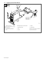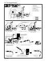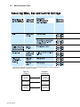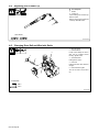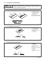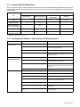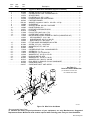
1
OM-1322 200 070K May 2003 Processes MIG (GMAW) Welding Pulsed MIG (GMAW-P) Flux Cored (FCAW) Welding Description Arc Welding Power Source and Wire Feeder R Millermatic Pulser M-15 Gun And Spoolmate 3035 Spool Gun Visit our website at www.MillerWelds.com From Miller to You Thank you and congratulations on choosing Miller. Now you can get the job done and get it done right. We know you don’t have time to do it any other way. That’s why when Niels Miller first started building arc welders in 1929, he made sure his products offered long-lasting value and superior quality. Like you, his customers couldn’t afford anything less. Miller products had to be more than the best they could be. They had to be the best you could buy. Today, the people that build and sell Miller products continue the tradition. They’re just as committed to providing equipment and service that meets the high standards of quality and value established in 1929. This Owner’s Manual is designed to help you get the most out of your Miller products. Please take time to read the Safety precautions. They will help you protect yourself against potential hazards on the worksite. We’ve made installation and operation quick and easy. With Miller you can count on years of reliable service with proper maintenance. And if for some reason the unit needs repair, there’s a Troubleshooting section that will help you figure out what the problem is. The Miller is the first welding parts list will then help you to decide the equipment manufacturer in exact part you may need to fix the problem. the U.S.A. to be registered to the ISO 9001:2000 Quality Warranty and service information for your System Standard. particular model are also provided. Working as hard as you do – every power source from Miller is backed by the most hassle-free warranty in the business. Miller offers a Technical Manual which provides more detailed service and parts information for your unit. To obtain a Technical Manual, contact your local distributor. Your distributor can also supply you with Welding Process Manuals such as SMAW, GTAW, GMAW, and GMAW-P. Miller Electric manufactures a full line of welders and welding related equipment. For information on other quality Miller products, contact your local Miller distributor to receive the latest full line catalog orindividual catalog sheets. To locate your nearest distributor or service agency call 1-800-4-A-Miller, or visit us at www.MillerWelds.com on the web. TABLE OF CONTENTS WARNING This product, when used for welding or cutting, produces fumes or gases which contain chemicals known to the State of California to cause birth defects and, in some cases, cancer. (California Health & Safety Code Section 25249.5 et seq.) The following terms are used interchangeably throughout this manual: MIG = GMAW OM-1322 SECTION 1 – SAFETY PRECAUTIONS - READ BEFORE USING . . . . . . . . . . . . . . . . . . . . . . . . . . . . 1-1. Symbol Usage . . . . . . . . . . . . . . . . . . . . . . . . . . . . . . . . . . . . . . . . . . . . . . . . . . . . . . . . . . . . . . . . 1-2. Arc Welding Hazards . . . . . . . . . . . . . . . . . . . . . . . . . . . . . . . . . . . . . . . . . . . . . . . . . . . . . . . . . . 1-3. Additional Symbols For Installation, Operation, And Maintenance . . . . . . . . . . . . . . . . . . . . . 1-4. Principal Safety Standards . . . . . . . . . . . . . . . . . . . . . . . . . . . . . . . . . . . . . . . . . . . . . . . . . . . . . 1-5. EMF Information . . . . . . . . . . . . . . . . . . . . . . . . . . . . . . . . . . . . . . . . . . . . . . . . . . . . . . . . . . . . . . 1 1 1 3 3 4 SECTION 1 – CONSIGNES DE SECURITE – LIRE AVANT UTILISATION . . . . . . . . . . . . . . . . . . . . . 1-1. Signification des symboles . . . . . . . . . . . . . . . . . . . . . . . . . . . . . . . . . . . . . . . . . . . . . . . . . . . . . 1-2. Dangers relatifs au soudage à l’arc . . . . . . . . . . . . . . . . . . . . . . . . . . . . . . . . . . . . . . . . . . . . . . 1-3. Dangers supplémentaires en relation avec l’installation, le fonctionnement et la maintenance . . . . . . . . . . . . . . . . . . . . . . . . . . . . . . . . . . . . . . . . . . . . . . . . . . . . . . . . . . . . . 1-4. Principales normes de sécurité . . . . . . . . . . . . . . . . . . . . . . . . . . . . . . . . . . . . . . . . . . . . . . . . . . 1-5. Information sur les champs électromagnétiques . . . . . . . . . . . . . . . . . . . . . . . . . . . . . . . . . . . . 5 5 5 SECTION 2 – INSTALLATION . . . . . . . . . . . . . . . . . . . . . . . . . . . . . . . . . . . . . . . . . . . . . . . . . . . . . . . . . . . 2-1. Welding Power Source And MIG Gun Specifications . . . . . . . . . . . . . . . . . . . . . . . . . . . . . . . . 2-2. Spool Gun Specifications . . . . . . . . . . . . . . . . . . . . . . . . . . . . . . . . . . . . . . . . . . . . . . . . . . . . . . . 2-3. Welding Power Source Duty Cycle And Overheating . . . . . . . . . . . . . . . . . . . . . . . . . . . . . . . . 2-4. MIG Welding Gun Duty Cycle And Overheating . . . . . . . . . . . . . . . . . . . . . . . . . . . . . . . . . . . . 2-5. Spool Gun Duty Cycle And Overheating . . . . . . . . . . . . . . . . . . . . . . . . . . . . . . . . . . . . . . . . . . 2-6. Volt-Ampere Curves . . . . . . . . . . . . . . . . . . . . . . . . . . . . . . . . . . . . . . . . . . . . . . . . . . . . . . . . . . . 2-7. Installing Cylinder Rack Wheels . . . . . . . . . . . . . . . . . . . . . . . . . . . . . . . . . . . . . . . . . . . . . . . . . 2-8. Installing Work Clamp . . . . . . . . . . . . . . . . . . . . . . . . . . . . . . . . . . . . . . . . . . . . . . . . . . . . . . . . . . 2-9. Installing MIG Welding Gun . . . . . . . . . . . . . . . . . . . . . . . . . . . . . . . . . . . . . . . . . . . . . . . . . . . . . 2-10. Connecting A Spool Gun . . . . . . . . . . . . . . . . . . . . . . . . . . . . . . . . . . . . . . . . . . . . . . . . . . . . . . . 2-11. Setting MIG Gun Polarity For Wire Type . . . . . . . . . . . . . . . . . . . . . . . . . . . . . . . . . . . . . . . . . . 2-12. Installing Gas Supply . . . . . . . . . . . . . . . . . . . . . . . . . . . . . . . . . . . . . . . . . . . . . . . . . . . . . . . . . . 2-13. Installing MIG Wire Spool and Adjusting Hub Tension . . . . . . . . . . . . . . . . . . . . . . . . . . . . . . . 2-14. Installing Spool Gun Wire Spool And Threading Welding Wire . . . . . . . . . . . . . . . . . . . . . . . . 2-15. Positioning Jumper Links . . . . . . . . . . . . . . . . . . . . . . . . . . . . . . . . . . . . . . . . . . . . . . . . . . . . . . . 2-16. Electrical Service Guide . . . . . . . . . . . . . . . . . . . . . . . . . . . . . . . . . . . . . . . . . . . . . . . . . . . . . . . . 2-17. Selecting A Location And Connecting Input Power . . . . . . . . . . . . . . . . . . . . . . . . . . . . . . . . . . 2-18. Threading Welding Wire . . . . . . . . . . . . . . . . . . . . . . . . . . . . . . . . . . . . . . . . . . . . . . . . . . . . . . . . 2-19. Installing Optional Curved Or 9 in Straight Barrel On Spoolmate 3035 Spool Gun . . . . . . . . 2-20. Using Gun/Cable Holder . . . . . . . . . . . . . . . . . . . . . . . . . . . . . . . . . . . . . . . . . . . . . . . . . . . . . . . 9 9 9 10 10 11 11 12 13 13 14 14 15 16 17 18 18 19 20 21 22 SECTION 3 – OPERATION . . . . . . . . . . . . . . . . . . . . . . . . . . . . . . . . . . . . . . . . . . . . . . . . . . . . . . . . . . . . . 3-1. Controls . . . . . . . . . . . . . . . . . . . . . . . . . . . . . . . . . . . . . . . . . . . . . . . . . . . . . . . . . . . . . . . . . . . . . 3-2. Weld Parameter Chart . . . . . . . . . . . . . . . . . . . . . . . . . . . . . . . . . . . . . . . . . . . . . . . . . . . . . . . . . 3-3. Parameter Adjustment Guide . . . . . . . . . . . . . . . . . . . . . . . . . . . . . . . . . . . . . . . . . . . . . . . . . . . 23 23 24 26 SECTION 4 – MAINTENANCE &TROUBLESHOOTING . . . . . . . . . . . . . . . . . . . . . . . . . . . . . . . . . . . . . 4-1. Routine Maintenance . . . . . . . . . . . . . . . . . . . . . . . . . . . . . . . . . . . . . . . . . . . . . . . . . . . . . . . . . . 4-2. Circuit Breaker CB1 . . . . . . . . . . . . . . . . . . . . . . . . . . . . . . . . . . . . . . . . . . . . . . . . . . . . . . . . . . . 4-3. Unit Overload . . . . . . . . . . . . . . . . . . . . . . . . . . . . . . . . . . . . . . . . . . . . . . . . . . . . . . . . . . . . . . . . 4-4. Replacing Gun Contact Tip . . . . . . . . . . . . . . . . . . . . . . . . . . . . . . . . . . . . . . . . . . . . . . . . . . . . . 4-5. Changing Drive Roll and Wire Inlet Guide . . . . . . . . . . . . . . . . . . . . . . . . . . . . . . . . . . . . . . . . . 4-6. Aligning Drive Rolls and Wire Guide . . . . . . . . . . . . . . . . . . . . . . . . . . . . . . . . . . . . . . . . . . . . . . 4-7. Removing Knob From Front Panel . . . . . . . . . . . . . . . . . . . . . . . . . . . . . . . . . . . . . . . . . . . . . . . 4-8. Cleaning Or Replacing Gun Liner . . . . . . . . . . . . . . . . . . . . . . . . . . . . . . . . . . . . . . . . . . . . . . . . 4-9. Replacing Switch And/Or Head Tube . . . . . . . . . . . . . . . . . . . . . . . . . . . . . . . . . . . . . . . . . . . . . 4-10. Changing Drive And Push Rolls On Spoolmate 3035 . . . . . . . . . . . . . . . . . . . . . . . . . . . . . . . . 4-11. Changing Liner On Spoolmate 3035 . . . . . . . . . . . . . . . . . . . . . . . . . . . . . . . . . . . . . . . . . . . . . . 4-12. Troubleshooting . . . . . . . . . . . . . . . . . . . . . . . . . . . . . . . . . . . . . . . . . . . . . . . . . . . . . . . . . . . . . . 4-13. Spool Gun Troubleshooting . . . . . . . . . . . . . . . . . . . . . . . . . . . . . . . . . . . . . . . . . . . . . . . . . . . . . 27 27 27 27 28 28 29 29 30 31 32 33 33 34 SECTION 5 – ELECTRICAL DIAGRAM . . . . . . . . . . . . . . . . . . . . . . . . . . . . . . . . . . . . . . . . . . . . . . . . . . . 35 7 8 8 (Continued) TABLE OF CONTENTS SECTION 6 – MIG WELDING (GMAW) GUIDELINES . . . . . . . . . . . . . . . . . . . . . . . . . . . . . . . . . . . . . . . 6-1. Typical MIG Process Connections . . . . . . . . . . . . . . . . . . . . . . . . . . . . . . . . . . . . . . . . . . . . . . . 6-2. Typical MIG Process Control Settings . . . . . . . . . . . . . . . . . . . . . . . . . . . . . . . . . . . . . . . . . . . . 6-3. Holding And Positioning Welding Gun . . . . . . . . . . . . . . . . . . . . . . . . . . . . . . . . . . . . . . . . . . . . 6-4. Conditions That Affect Weld Bead Shape . . . . . . . . . . . . . . . . . . . . . . . . . . . . . . . . . . . . . . . . . 6-5. Gun Movement During Welding . . . . . . . . . . . . . . . . . . . . . . . . . . . . . . . . . . . . . . . . . . . . . . . . . 6-6. Poor Weld Bead Characteristics . . . . . . . . . . . . . . . . . . . . . . . . . . . . . . . . . . . . . . . . . . . . . . . . . 6-7. Good Weld Bead Characteristics . . . . . . . . . . . . . . . . . . . . . . . . . . . . . . . . . . . . . . . . . . . . . . . . 6-8. Troubleshooting – Excessive Spatter . . . . . . . . . . . . . . . . . . . . . . . . . . . . . . . . . . . . . . . . . . . . . 6-9. Troubleshooting – Porosity . . . . . . . . . . . . . . . . . . . . . . . . . . . . . . . . . . . . . . . . . . . . . . . . . . . . . 6-10. Troubleshooting – Excessive Penetration . . . . . . . . . . . . . . . . . . . . . . . . . . . . . . . . . . . . . . . . . 6-11. Troubleshooting – Lack Of Penetration . . . . . . . . . . . . . . . . . . . . . . . . . . . . . . . . . . . . . . . . . . . 6-12. Troubleshooting – Incomplete Fusion . . . . . . . . . . . . . . . . . . . . . . . . . . . . . . . . . . . . . . . . . . . . . 6-13. Troubleshooting – Burn-Through . . . . . . . . . . . . . . . . . . . . . . . . . . . . . . . . . . . . . . . . . . . . . . . . . 6-14. Troubleshooting – Waviness Of Bead . . . . . . . . . . . . . . . . . . . . . . . . . . . . . . . . . . . . . . . . . . . . 6-15. Troubleshooting – Distortion . . . . . . . . . . . . . . . . . . . . . . . . . . . . . . . . . . . . . . . . . . . . . . . . . . . . 6-16. Common MIG Shielding Gases . . . . . . . . . . . . . . . . . . . . . . . . . . . . . . . . . . . . . . . . . . . . . . . . . . 6-17. Troubleshooting Guide For Semiautomatic Welding Equipment . . . . . . . . . . . . . . . . . . . . . . . 37 37 38 39 40 41 41 41 42 42 42 43 43 43 44 44 45 45 SECTION 7 – PARTS LIST . . . . . . . . . . . . . . . . . . . . . . . . . . . . . . . . . . . . . . . . . . . . . . . . . . . . . . . . . . . . . . 48 OPTIONS AND ACCESSORIES WARRANTY SECTION 1 – SAFETY PRECAUTIONS - READ BEFORE USING som _nd_4/98 1-1. Symbol Usage Means Warning! Watch Out! There are possible hazards with this procedure! The possible hazards are shown in the adjoining symbols. Y Marks a special safety message. . Means “Note”; not safety related. This group of symbols means Warning! Watch Out! possible ELECTRIC SHOCK, MOVING PARTS, and HOT PARTS hazards. Consult symbols and related instructions below for necessary actions to avoid the hazards. 1-2. Arc Welding Hazards Y The symbols shown below are used throughout this manual to call attention to and identify possible hazards. When you see the symbol, watch out, and follow the related instructions to avoid the hazard. The safety information given below is only a summary of the more complete safety information found in the Safety Standards listed in Section 1-4. Read and follow all Safety Standards. D If earth grounding of the workpiece is required, ground it directly with a separate cable. Y Only qualified persons should install, operate, maintain, and repair this unit. D Wear a safety harness if working above floor level. D Keep all panels and covers securely in place. Y During operation, keep everybody, especially children, away. D Clamp work cable with good metal-to-metal contact to workpiece or worktable as near the weld as practical. ELECTRIC SHOCK can kill. Touching live electrical parts can cause fatal shocks or severe burns. The electrode and work circuit is electrically live whenever the output is on. The input power circuit and machine internal circuits are also live when power is on. In semiautomatic or automatic wire welding, the wire, wire reel, drive roll housing, and all metal parts touching the welding wire are electrically live. Incorrectly installed or improperly grounded equipment is a hazard. D Do not touch electrode if you are in contact with the work, ground, or another electrode from a different machine. D Use only well-maintained equipment. Repair or replace damaged parts at once. Maintain unit according to manual. D Insulate work clamp when not connected to workpiece to prevent contact with any metal object. D Do not connect more than one electrode or work cable to any single weld output terminal. SIGNIFICANT DC VOLTAGE exists after removal of input power on inverters. D Turn Off inverter, disconnect input power, and discharge input capacitors according to instructions in Maintenance Section before touching any parts. D Do not touch live electrical parts. D Wear dry, hole-free insulating gloves and body protection. D Insulate yourself from work and ground using dry insulating mats or covers big enough to prevent any physical contact with the work or ground. D Do not use AC output in damp areas, if movement is confined, or if there is a danger of falling. D Use AC output ONLY if required for the welding process. D If AC output is required, use remote output control if present on unit. D Disconnect input power or stop engine before installing or servicing this equipment. Lockout/tagout input power according to OSHA 29 CFR 1910.147 (see Safety Standards). D Properly install and ground this equipment according to its Owner’s Manual and national, state, and local codes. D Keep your head out of the fumes. Do not breathe the fumes. D Always verify the supply ground – check and be sure that input power cord ground wire is properly connected to ground terminal in disconnect box or that cord plug is connected to a properly grounded receptacle outlet. D When making input connections, attach proper grounding conductor first – double-check connections. D Frequently inspect input power cord for damage or bare wiring – replace cord immediately if damaged – bare wiring can kill. D Turn off all equipment when not in use. D Do not use worn, damaged, undersized, or poorly spliced cables. D Do not weld in locations near degreasing, cleaning, or spraying operations. The heat and rays of the arc can react with vapors to form highly toxic and irritating gases. D Do not drape cables over your body. FUMES AND GASES can be hazardous. Welding produces fumes and gases. Breathing these fumes and gases can be hazardous to your health. D If inside, ventilate the area and/or use exhaust at the arc to remove welding fumes and gases. D If ventilation is poor, use an approved air-supplied respirator. D Read the Material Safety Data Sheets (MSDSs) and the manufacturer’s instructions for metals, consumables, coatings, cleaners, and degreasers. D Work in a confined space only if it is well ventilated, or while wearing an air-supplied respirator. Always have a trained watchperson nearby. Welding fumes and gases can displace air and lower the oxygen level causing injury or death. Be sure the breathing air is safe. D Do not weld on coated metals, such as galvanized, lead, or cadmium plated steel, unless the coating is removed from the weld area, the area is well ventilated, and if necessary, while wearing an air-supplied respirator. The coatings and any metals containing these elements can give off toxic fumes if welded. OM-1322 Page 1 ARC RAYS can burn eyes and skin. Arc rays from the welding process produce intense visible and invisible (ultraviolet and infrared) rays that can burn eyes and skin. Sparks fly off from the weld. D Wear a welding helmet fitted with a proper shade of filter to protect your face and eyes when welding or watching (see ANSI Z49.1 and Z87.1 listed in Safety Standards). D Wear approved safety glasses with side shields under your helmet. D Use protective screens or barriers to protect others from flash and glare; warn others not to watch the arc. D Wear protective clothing made from durable, flame-resistant material (leather and wool) and foot protection. BUILDUP OF GAS can injure or kill. D Shut off shielding gas supply when not in use. D Always ventilate confined spaces or use approved air-supplied respirator. HOT PARTS can cause severe burns. D Do not touch hot parts bare handed. D Allow cooling period before working on gun or torch. MAGNETIC FIELDS can affect pacemakers. WELDING can cause fire or explosion. Welding on closed containers, such as tanks, drums, or pipes, can cause them to blow up. Sparks can fly off from the welding arc. The flying sparks, hot workpiece, and hot equipment can cause fires and burns. Accidental contact of electrode to metal objects can cause sparks, explosion, overheating, or fire. Check and be sure the area is safe before doing any welding. D Protect yourself and others from flying sparks and hot metal. D Do not weld where flying sparks can strike flammable material. D Remove all flammables within 35 ft (10.7 m) of the welding arc. If this is not possible, tightly cover them with approved covers. D Be alert that welding sparks and hot materials from welding can easily go through small cracks and openings to adjacent areas. D Watch for fire, and keep a fire extinguisher nearby. D Be aware that welding on a ceiling, floor, bulkhead, or partition can cause fire on the hidden side. D Do not weld on closed containers such as tanks, drums, or pipes, unless they are properly prepared according to AWS F4.1 (see Safety Standards). D Connect work cable to the work as close to the welding area as practical to prevent welding current from traveling long, possibly unknown paths and causing electric shock and fire hazards. D Do not use welder to thaw frozen pipes. D Remove stick electrode from holder or cut off welding wire at contact tip when not in use. D Wear oil-free protective garments such as leather gloves, heavy shirt, cuffless trousers, high shoes, and a cap. D Remove any combustibles, such as a butane lighter or matches, from your person before doing any welding. FLYING METAL can injure eyes. D Welding, chipping, wire brushing, and grinding cause sparks and flying metal. As welds cool, they can throw off slag. D Wear approved safety glasses with side shields even under your welding helmet. OM-1322 Page 2 D Pacemaker wearers keep away. D Wearers should consult their doctor before going near arc welding, gouging, or spot welding operations. NOISE can damage hearing. Noise from some processes or equipment can damage hearing. D Wear approved ear protection if noise level is high. CYLINDERS can explode if damaged. Shielding gas cylinders contain gas under high pressure. If damaged, a cylinder can explode. Since gas cylinders are normally part of the welding process, be sure to treat them carefully. D Protect compressed gas cylinders from excessive heat, mechanical shocks, slag, open flames, sparks, and arcs. D Install cylinders in an upright position by securing to a stationary support or cylinder rack to prevent falling or tipping. D Keep cylinders away from any welding or other electrical circuits. D Never drape a welding torch over a gas cylinder. D Never allow a welding electrode to touch any cylinder. D Never weld on a pressurized cylinder – explosion will result. D Use only correct shielding gas cylinders, regulators, hoses, and fittings designed for the specific application; maintain them and associated parts in good condition. D Turn face away from valve outlet when opening cylinder valve. D Keep protective cap in place over valve except when cylinder is in use or connected for use. D Read and follow instructions on compressed gas cylinders, associated equipment, and CGA publication P-1 listed in Safety Standards. 1-3. Additional Symbols For Installation, Operation, And Maintenance FIRE OR EXPLOSION hazard. MOVING PARTS can cause injury. D Do not install or place unit on, over, or near combustible surfaces. D Do not install unit near flammables. D Do not overload building wiring – be sure power supply system is properly sized, rated, and protected to handle this unit. D Keep away from moving parts such as fans. D Keep all doors, panels, covers, and guards closed and securely in place. FALLING UNIT can cause injury. H.F. RADIATION can cause interference. D Use lifting eye to lift unit only, NOT running gear, gas cylinders, or any other accessories. D Use equipment of adequate capacity to lift and support unit. D If using lift forks to move unit, be sure forks are long enough to extend beyond opposite side of unit. D OVERUSE can cause OVERHEATING D D Allow cooling period; follow rated duty cycle. D Reduce current or reduce duty cycle before starting to weld again. D Do not block or filter airflow to unit. D D D High-frequency (H.F.) can interfere with radio navigation, safety services, computers, and communications equipment. D Have only qualified persons familiar with electronic equipment perform this installation. The user is responsible for having a qualified electrician promptly correct any interference problem resulting from the installation. If notified by the FCC about interference, stop using the equipment at once. Have the installation regularly checked and maintained. Keep high-frequency source doors and panels tightly shut, keep spark gaps at correct setting, and use grounding and shielding to minimize the possibility of interference. STATIC (ESD) can damage PC boards. D Put on grounded wrist strap BEFORE handling boards or parts. D Use proper static-proof bags and boxes to store, move, or ship PC boards. ARC WELDING can cause interference. MOVING PARTS can cause injury. D Keep away from moving parts. D Keep away from pinch points such as drive rolls. D D WELDING WIRE can cause injury. D Do not press gun trigger until instructed to do so. D Do not point gun toward any part of the body, other people, or any metal when threading welding wire. D D D Electromagnetic energy can interfere with sensitive electronic equipment such as computers and computer-driven equipment such as robots. D Be sure all equipment in the welding area is electromagnetically compatible. To reduce possible interference, keep weld cables as short as possible, close together, and down low, such as on the floor. Locate welding operation 100 meters from any sensitive electronic equipment. Be sure this welding machine is installed and grounded according to this manual. If interference still occurs, the user must take extra measures such as moving the welding machine, using shielded cables, using line filters, or shielding the work area. 1-4. Principal Safety Standards Safety in Welding and Cutting, ANSI Standard Z49.1, from American Welding Society, 550 N.W. LeJeune Rd, Miami FL 33126 Safety and Health Standards, OSHA 29 CFR 1910, from Superintendent of Documents, U.S. Government Printing Office, Washington, D.C. 20402. Recommended Safe Practices for the Preparation for Welding and Cutting of Containers That Have Held Hazardous Substances, American Welding Society Standard AWS F4.1, from American Welding Society, 550 N.W. LeJeune Rd, Miami, FL 33126 National Electrical Code, NFPA Standard 70, from National Fire Protection Association, Batterymarch Park, Quincy, MA 02269. Safe Handling of Compressed Gases in Cylinders, CGA Pamphlet P-1, from Compressed Gas Association, 1235 Jefferson Davis Highway, Suite 501, Arlington, VA 22202. Code for Safety in Welding and Cutting, CSA Standard W117.2, from Canadian Standards Association, Standards Sales, 178 Rexdale Boulevard, Rexdale, Ontario, Canada M9W 1R3. Safe Practices For Occupation And Educational Eye And Face Protection, ANSI Standard Z87.1, from American National Standards Institute, 1430 Broadway, New York, NY 10018. Cutting And Welding Processes, NFPA Standard 51B, from National Fire Protection Association, Batterymarch Park, Quincy, MA 02269. OM-1322 Page 3 1-5. EMF Information Considerations About Welding And The Effects Of Low Frequency Electric And Magnetic Fields Welding current, as it flows through welding cables, will cause electromagnetic fields. There has been and still is some concern about such fields. However, after examining more than 500 studies spanning 17 years of research, a special blue ribbon committee of the National Research Council concluded that: “The body of evidence, in the committee’s judgment, has not demonstrated that exposure to powerfrequency electric and magnetic fields is a human-health hazard.” However, studies are still going forth and evidence continues to be examined. Until the final conclusions of the research are reached, you may wish to minimize your exposure to electromagnetic fields when welding or cutting. To reduce magnetic fields in the workplace, use the following procedures: OM-1322 Page 4 1. Keep cables close together by twisting or taping them. 2. Arrange cables to one side and away from the operator. 3. Do not coil or drape cables around your body. 4. Keep welding power source and cables as far away from operator as practical. 5. Connect work clamp to workpiece as close to the weld as possible. About Pacemakers: Pacemaker wearers consult your doctor first. If cleared by your doctor, then following the above procedures is recommended. SECTION 1 – CONSIGNES DE SECURITE – LIRE AVANT UTILISATION som _nd_fre 4/98 1-1. Signification des symboles Signifie Mise en garde ! Soyez vigilant ! Cette procédure présente des risques de danger ! Ceux-ci sont identifiés par des symboles adjacents aux directives. Y Identifie un message de sécurité particulier. . Signifie NOTA ; n’est pas relatif à la sécurité. Ce groupe de symboles signifie Mise en garde ! Soyez vigilant ! Il y a des risques de danger reliés aux CHOCS ÉLECTRIQUES, aux PIÈCES EN MOUVEMENT et aux PIÈCES CHAUDES. Reportez-vous aux symboles et aux directives ci-dessous afin de connaître les mesures à prendre pour éviter tout danger. 1-2. Dangers relatifs au soudage à l’arc Y Les symboles présentés ci-après sont utilisés tout au long du présent manuel pour attirer votre attention et identifier les risques de danger. Lorsque vous voyez un symbole, soyez vigilant et suivez les directives mentionnées afin d’éviter tout danger. Les consignes de sécurité présentées ci-après ne font que résumer l’information contenue dans les normes de sécurité énumérées à la section 1-4. Veuillez lire et respecter toutes ces normes de sécurité. Y L’installation, l’utilisation, l’entretien et les réparations ne doivent être confiés qu’à des personnes qualifiées. Y Au cours de l’utilisation, tenir toute personne à l’écart et plus particulièrement les enfants. D N’utiliser qu’un matériel en bon état. Réparer ou remplacer sur-lechamp les pièces endommagées. Entretenir l’appareil conformément à ce manuel. D Porter un harnais de sécurité quand on travaille en hauteur. D Maintenir solidement en place tous les panneaux et capots. D Fixer le câble de retour de façon à obtenir un bon contact métal-métal avec la pièce à souder ou la table de travail, le plus près possible de la soudure. D Isoler la pince de masse quand pas mis à la pièce pour éviter le contact avec tout objet métallique. UN CHOC ÉLECTRIQUE peut tuer. Un simple contact avec des pièces électriques peut provoquer une électrocution ou des blessures graves. L’électrode et le circuit de soudage sont sous tension dès que l’appareil est sur ON. Le circuit d’entrée et les circuits internes de l’appareil sont également sous tension à ce moment-là. En soudage semi-automatique ou automatique, le fil, le dévidoir, le logement des galets d’entraînement et les pièces métalliques en contact avec le fil de soudage sont sous tension. Des matériels mal installés ou mal mis à la terre présentent un danger. Il y a DU COURANT CONTINU IMPORTANT dans les convertisseurs après la suppression de l’alimentation électrique. D Arrêter les convertisseurs, débrancher le courant électrique, et décharger les condensateurs d’alimentation selon les instructions indiquées dans la partie entretien avant de toucher les pièces. D Ne jamais toucher les pièces électriques sous tension. D Porter des gants et des vêtements de protection secs ne comportant pas de trous. D S’isoler de la pièce et de la terre au moyen de tapis ou d’autres moyens isolants suffisamment grands pour empêcher le contact physique éventuel avec la pièce ou la terre. D D D Ne pas se servir de source électrique àcourant électrique dans les zones humides, dans les endroits confinés ou là où on risque de tomber. Se servir d’une source électrique àcourant électrique UNIQUEMENT si le procédé de soudage le demande. Si l’utilisation d’une source électrique àcourant électrique s’avère nécessaire, se servir de la fonction de télécommande si l’appareil en est équipé. D Couper l’alimentation ou arrêter le moteur avant de procéder à l’installation, à la réparation ou à l’entretien de l’appareil. Déverrouiller l’alimentation selon la norme OSHA 29 CFR 1910.147 (voir normes de sécurité). D Installer et mettre à la terre correctement cet appareil conformément à son manuel d’utilisation et aux codes nationaux, provinciaux et municipaux. D Toujours vérifier la terre du cordon d’alimentation – Vérifier et s’assurer que le fil de terre du cordon d’alimentation est bien raccordé à la borne de terre du sectionneur ou que la fiche du cordon est raccordée à une prise correctement mise à la terre. D En effectuant les raccordements d’entrée fixer d’abord le conducteur de mise à la terre approprié et contre-vérifier les connexions. D Vérifier fréquemment le cordon d’alimentation pour voir s’il n’est pas endommagé ou dénudé – remplacer le cordon immédiatement s’il est endommagé – un câble dénudé peut provoquer une électrocution. D Mettre l’appareil hors tension quand on ne l’utilise pas. D Ne pas utiliser des câbles usés, endommagés, de grosseur insuffisante ou mal épissés. D Ne pas enrouler les câbles autour du corps. D Si la pièce soudée doit être mise à la terre, le faire directement avec un câble distinct. D Ne pas toucher l’électrode quand on est en contact avec la pièce, la terre ou une électrode provenant d’une autre machine. LES FUMÉES ET LES GAZ peuvent être dangereux. Le soudage génère des fumées et des gaz. Leur inhalation peut être dangereux pour votre santé. D D D D D D D Eloigner votre tête des fumées. Ne pas respirer les fumées. A l’intérieur, ventiler la zone et/ou utiliser un échappement au niveau de l’arc pour l’évacuation des fumées et des gaz de soudage. Si la ventilation est insuffisante, utiliser un respirateur à alimentation d’air homologué. Lire les spécifications de sécurité des matériaux (MSDSs) et les instructions du fabricant concernant les métaux, les consommables, les revêtements, les nettoyants et les dégraisseurs. Travailler dans un espace fermé seulement s’il est bien ventilé ou en portant un respirateur à alimentation d’air. Demander toujours à un surveillant dûment formé de se tenir à proximité. Des fumées et des gaz de soudage peuvent déplacer l’air et abaisser le niveau d’oxygène provoquant des blessures ou des accidents mortels. S’assurer que l’air de respiration ne présente aucun danger. Ne pas souder dans des endroits situés à proximité d’opérations de dégraissage, de nettoyage ou de pulvérisation. La chaleur et les rayons de l’arc peuvent réagir en présence de vapeurs et former des gaz hautement toxiques et irritants. Ne pas souder des métaux munis d’un revêtement, tels que l’acier galvanisé, plaqué en plomb ou au cadmium à moins que le revêtement n’ait été enlevé dans la zone de soudure, que l’endroit soit bien ventilé, et si nécessaire, en portant un respirateur à alimentation d’air. Les revêtements et tous les métaux renfermant ces éléments peuvent dégager des fumées toxiques en cas de soudage. OM-1322 Page 5 LES RAYONS DE L’ARC peuvent provoquer des brûlures dans les yeux et sur la peau. Le rayonnement de l’arc du procédé de soudage génère des rayons visibles et invisibles intenses (ultraviolets et infrarouges) susceptibles de provoquer des brûlures dans les yeux et sur la peau. Des étincelles sont projetées pendant le soudage. D Porter un casque de soudage muni d’un écran de filtre approprié pour protéger votre visage et vos yeux pendant le soudage ou pour regarder (voir ANSI Z49.1 et Z87.1 énuméré dans les normes de sécurité). D Porter des protections approuvés pour les oreilles si le niveau sondre est trop élevé. D Utiliser des écrans ou des barrières pour protéger des tiers de l’éclair et de l’éblouissement; demander aux autres personnes de ne pas regarder l’arc. D Porter des vêtements de protection constitué dans une matière durable, résistant au feu (cuir ou laine) et une protection des pieds. LE SOUDAGE peut provoquer un incendie ou une explosion. Le soudage effectué sur des conteneurs fermés tels que des réservoirs, tambours ou des conduites peut provoquer leur éclatement. Des étincelles peuvent être projetées de l’arc de soudure. La projection d’étincelles, des pièces chaudes et des équipements chauds peut provoquer des incendies et des brûlures. Le contact accidentel de l’électrode avec des objets métalliques peut provoquer des étincelles, une explosion, un surchauffement ou un incendie. Avant de commencer le soudage, vérifier et s’assurer que l’endroit ne présente pas de danger. D Se protéger et d’autres personnes de la projection d’étincelles et de métal chaud. D Ne pas souder dans un endroit là où des étincelles peuvent tomber sur des substances inflammables. D Déplacer toutes les substances inflammables à une distance de 10,7 m de l’arc de soudage. En cas d’impossibilité les recouvrir soigneusement avec des protections homologués. D Des étincelles et des matériaux chauds du soudage peuvent facilement passer dans d’autres zones en traversant de petites fissures et des ouvertures. D Surveiller tout déclenchement d’incendie et tenir un extincteur à proximité. D Le soudage effectué sur un plafond, plancher, paroi ou séparation peut déclencher un incendie de l’autre côté. D Ne pas effectuer le soudage sur des conteneurs fermés tels que des réservoirs, tambours, ou conduites, à moins qu’ils n’aient été préparés correctement conformément à AWS F4.1 (voir les normes de sécurité). D Brancher le câble sur la pièce le plus près possible de la zone de soudage pour éviter le transport du courant sur une longue distance par des chemins inconnus éventuels en provoquant des risques d’électrocution et d’incendie. D Ne pas utiliser le poste de soudage pour dégeler des conduites gelées. D En cas de non utilisation, enlever la baguette d’électrode du porteélectrode ou couper le fil à la pointe de contact. D Porter des vêtements de protection dépourvus d’huile tels que des gants en cuir, une chemise en matériau lourd, des pantalons sans revers, des chaussures hautes et un couvre chef. D Avant de souder, retirer toute substance combustible de vos poches telles qu’un allumeur au butane ou des allumettes. DES PARTICULES VOLANTES peuvent blesser les yeux. D Le soudage, l’écaillement, le passage de la pièce à la brosse en fil de fer, et le meulage génèrent des étincelles et des particules métalliques volantes. Pendant la période de refroidissement des soudures, elles risquent de projeter du laitier. D Porter des lunettes de sécurité avec écrans latéraux ou un écran facial. OM-1322 Page 6 LES ACCUMULATIONS DE GAZ risquent de provoquer des blessures ou même la mort. D D Fermer l’alimentation du gaz protecteur en cas de non utilisation. Veiller toujours à bien aérer les espaces confinés ou se servir d’un respirateur d’adduction d’air homologué. DES PIÈCES CHAUDES peuvent provoquer des brûlures graves. D Ne pas toucher des parties chaudes à mains nues D Prévoir une période de refroidissement avant d’utiliser le pistolet ou la torche. LES CHAMPS MAGNÉTIQUES peuvent affecter les stimulateurs cardiaques. D D Porteurs de stimulateur cardiaque, restez à distance. Les porteurs d’un stimulateur cardiaque doivent d’abord consulter leur médecin avant de s’approcher des opérations de soudage à l’arc, de gougeage ou de soudage par points. LE BRUIT peut affecter l’ouïe. Le bruit des processus et des équipements peut affecter l’ouïe. D Porter des protections approuvés pour les oreilles si le niveau sondre est trop élevé. Si des BOUTEILLES sont endommagées, elles pourront exploser. Des bouteilles de gaz protecteur contiennent du gaz sous haute pression. Si une bouteille est endommagée, elle peut exploser. Du fait que les bouteilles de gaz font normalement partie du procédé de soudage, les manipuler avec précaution. D Protéger les bouteilles de gaz comprimé d’une chaleur excessive, des chocs mécaniques, du laitier, des flammes ouvertes, des étincelles et des arcs. D Placer les bouteilles debout en les fixant dans un support stationnaire ou dans un porte-bouteilles pour les empêcher de tomber ou de se renverser. D Tenir les bouteilles éloignées des circuits de soudage ou autres circuits électriques. D Ne jamais placer une torche de soudage sur une bouteille à gaz. D Une électrode de soudage ne doit jamais entrer en contact avec une bouteille. D Ne jamais souder une bouteille pressurisée – risque d’explosion. D Utiliser seulement des bouteilles de gaz protecteur, régulateurs, tuyaux et raccords convenables pour cette application spécifique; les maintenir ainsi que les éléments associés en bon état. D Ne pas tenir la tête en face de la sortie en ouvrant la soupape de la bouteille. D Maintenir le chapeau de protection sur la soupape, sauf en cas d’utilisation ou de branchement de la bouteille. D Lire et suivre les instructions concernant les bouteilles de gaz comprimé, les équipements associés et les publications P-1 CGA énumérées dans les normes de sécurité. 1-3. Dangers supplémentaires en relation avec l’installation, le fonctionnement et la maintenance Risque D’INCENDIE OU D’EXPLOSION. DES ORGANES MOBILES peuvent provoquer des blessures. D Ne pas placer l’appareil sur, au-dessus ou à proximité de surfaces infllammables. D Rester à l’écart des organes mobiles comme le ventilateur. D Maintenir fermés et fixement en place les portes, panneaux, recouvrements et dispositifs de protection. D Ne pas installer l’appareil à proximité de produits inflammables D Ne pas surcharger l’installation électrique – s”assurer que l’alimentation est correctement dimensionné et protégé avant de mettre l’appareil en service. LE RAYONNEMENT HAUTE FRÉQUENCE (H.F.) risque de provoquer des interférences. LA CHUTE DE L’APPAREIL peut blesser. D Utiliser l’anneau de levage uniquement pour soulever l’appareil, NON PAS les chariot, les bouteilles de gaz ou tout autre accessoire. D Utiliser un engin d’une capacité appropriée pour soulever l’appareil. D En utilisant des fourches de levage pour déplacer l’unité, s’assurer que les fourches sont suffisamment longues pour dépasser du côté opposé de l’appareil. L’EMPLOI EXCESSIF peut SURCHAUFFER L’ÉQUIPEMENT. D D D D D D Prévoir une période de refroidissement, respecter le cycle opératoire nominal. D Réduire le courant ou le cycle opératoire avant de recommancer le soudage. LE SOUDAGE À L’ARC risque de provoquer des interférences. D Ne pas obstruer les passages d’air du poste. LES CHARGES ÉLECTROSTATIQUES peuvent endommager les circuits imprimés. D Établir la connexion avec la barrette de terre avant de manipuler des cartes ou des pièces. D Utiliser des pochettes et des boîtes antistatiques pour stocker, déplacer ou expédier des cartes de circuits imprimes. DES ORGANES MOBILES peuvent provoquer des blessures. D Ne pas s’approcher des organes mobiles. D Ne pas s’approcher des points de coincement tels que des rouleaux de commande. LES FILS DE SOUDAGE peuvent provoquer des blessures. D Ne pas appuyer sur la gachette avant d’en avoir reçu l’instruction. D Ne pas diriger le pistolet vers soi, d’autres personnes ou toute pièce mécanique en engageant le fil de soudage. D Le rayonnement haute frequence peut provoquer des interférences avec les équipements de radio–navigation et de communication, les services de sécurité et les ordinateurs. Demander seulement à des personnes qualifiées familiarisées avec des équipements électroniques de faire fonctionner l’installation. L’utilisateur est tenu de faire corriger rapidement par un électricien qualifié les interférences résultant de l’installation. Si le FCC signale des interférences, arrêter immédiatement l’appareil. Effectuer régulièrement le contrôle et l’entretien de l’installation. Maintenir soigneusement fermés les portes et les panneaux des sources de haute fréquence, maintenir les éclateurs à une distance correcte et utiliser une terre et et un blindage pour réduire les interférences éventuelles. D D D D D D L’énergie électromagnétique risque de provoquer des interférences pour l’équipement électronique sensible tel que les ordinateurs et l’équipement commandé par ordinateur tel que les robots. Veiller à ce que tout l’équipement de la zone de soudage soit compatible électromagnétiquement. Pour réduire la possibilité d’interférence, maintenir les câbles de soudage aussi courts que possible, les grouper, et les poser aussi bas que possible (ex. par terre). Veiller à souder à une distance de 100 mètres de tout équipement électronique sensible. Veiller à ce que ce poste de soudage soit posé et mis à la terre conformément à ce mode d’emploi. En cas d’interférences après avoir pris les mesures précédentes, il incombe à l’utilisateur de prendre des mesures supplémentaires telles que le déplacement du poste, l’utilisation de câbles blindés, l’utilisation de filtres de ligne ou la pose de protecteurs dans la zone de travail. LES CHAMPS MAGNÉTIQUES peuvent affecter les stimulateurs cardiaques. D Porteurs de stimulateur cardiaque, restez à distance. D Les porteurs d’un stimulateur cardiaque doivent d’abord consulter leur médecin avant de s’approcher des opérations de soudage à l’arc, de gougeage ou de soudage par points. OM-1322 Page 7 1-4. Principales normes de sécurité Safety in Welding and Cutting, norme ANSI Z49.1, de l’American Welding Society, 550 N.W. Lejeune Rd, Miami FL 33126 Safety and Health Sandards, OSHA 29 CFR 1910, du Superintendent of Documents, U.S. Government Printing Office, Washington, D.C. 20402. Recommended Safe Practice for the Preparation for Welding and Cutting of Containers That Have Held Hazardous Substances, norme AWS F4.1, de l’American Welding Society, 550 N.W. Lejeune Rd, Miami FL 33126 National Electrical Code, NFPA Standard 70, de la National Fire Protection Association, Batterymarch Park, Quincy, MA 02269. Safe Handling of Compressed Gases in Cylinders, CGA Pamphlet P-1, de la Compressed Gas Association, 1235 Jefferson Davis Highway, Suite 501, Arlington, VA 22202. Règles de sécurité en soudage, coupage et procédés connexes, norme CSA W117.2, de l’Association canadienne de normalisation, vente de normes, 178 Rexdale Boulevard, Rexdale (Ontario) Canada M9W 1R3. Safe Practices For Occupation And Educational Eye And Face Protection, norme ANSI Z87.1, de l’American National Standards Institute, 1430 Broadway, New York, NY 10018. Cutting and Welding Processes, norme NFPA 51B, de la National Fire Protection Association, Batterymarch Park, Quincy, MA 02269. 1-5. Information sur les champs électromagnétiques Données sur le soudage électrique et sur les effets, pour l’organisme, des champs magnétiques basse fréquence Afin de réduire les champs électromagnétiques dans l’environnement de travail, respecter les consignes suivantes : 1 Le courant de soudage, pendant son passage dans les câbles de soudage, causera des champs électromagnétiques. Il y a eu et il y a encore un certain souci à propos de tels champs. Cependant, après avoir examiné plus de 500 études qui ont été faites pendant une période de recherche de 17 ans, un comité spécial ruban bleu du National Research Council a conclu: “L’accumulation de preuves, suivant le jugement du comité, n’a pas démontré que l’exposition aux champs magnétiques et champs électriques à haute fréquence représente un risque à la santé humaine”. Toutefois, des études sont toujours en cours et les preuves continuent à être examinées. En attendant que les conclusions finales de la recherche soient établies, il vous serait souhaitable de réduire votre exposition aux champs électromagnétiques pendant le soudage ou le coupage. OM-1322 Page 8 2 3 4 5 Garder les câbles ensembles en les torsadant ou en les attachant avec du ruban adhésif. Mettre tous les câbles du côté opposé de l’opérateur. Ne pas courber pas et ne pas entourer pas les câbles autour de votre corps. Garder le poste de soudage et les câbles le plus loin possible de vous. Relier la pince de masse le plus près possible de la zone de soudure. Consignes relatives aux stimulateurs cardiaques : Les personnes qui portent un stimulateur cardiaque doivent avant tout consulter leur docteur. Si vous êtes déclaré apte par votre docteur, il est alors recommandé de respecter les consignes ci–dessus. SECTION 2 – INSTALLATION 2-1. Welding Power Source And MIG Gun Specifications Rated Output 160 A at 26 VDC, 60% Duty Cycle Amperage Range DC Max. Open Circuit Voltage DC 30-200 36 Amps Input at Rated Output, 50 or 60 Hz, Single-Phase 200 (208) V 230 V 240 V 460 575 KVA KW 32 2.1* 28 1.8* 27 1.7* 14 0.9* 11 0.7* 6.36 0.51* 5.45 0.26* *While idling Wire Type and Diameter Solid Steel Stainless Steel Flux Cored .023 – .035 in (0.6 – 1.2 mm) .023 – .035 in (0.6 – 0.9 mm) .030 – .045 in (0.8 – 1.2 mm) Operating Temperature Range – –20C to +40C Wire Feed Speed Maximum Spool Size Dimensions Net Weight 25–700 IPM (.65–17.8 m/min) 12 in (305 mm) Diameter 33 lb (15 kg) H: 32 in (813 mm) W: 26 in (660 mm) D: 46 in (1168 mm) 225 lb (102 kg) Storage Temperature Range – -30C to + 50C 2-2. Spool Gun Specifications Wire Diameter Range .023 Thru .035 in (0.6 Thru 0.9 mm) Aluminum Wire .023 Thru 035 in (0.6 Thru 0.9 mm) Hard Or Cored Wire Approximate Wire Feed Range 115 To 715 ipm (4.1 To 20.4 mpm) Cooling Method Air Cooled Maximum Spool Size 4 in (102 mm) Diameter Overall Dimensions Length: 11-1/2 in (291 mm) Width: 2-1/4 in (57 mm) Weight 9.1 lb (4.1 kg) Gun With Cable Height: 8 in (203 mm) OM-1322 Page 9 2-3. Welding Power Source Duty Cycle And Overheating Duty Cycle is percentage of 10 minutes that unit can weld at rated load without overheating. If unit overheats, thermostat(s) opens, output stops, and cooling fan runs. Wait fifteen minutes for unit to cool. Reduce amperage or voltage, or duty cycle before welding. Y Exceeding duty cycle can damage unit and void warranty. 60% Duty Cycle At 160 Amperes 6 Minutes Welding 30% Duty Cycle At 200 Amperes 4 Minutes Resting 3 Minutes Welding 7 Minutes Resting Overheating A or V 0 15 OR Reduce Duty Cycle Minutes duty1 4/95 – 200 060 2-4. MIG Welding Gun Duty Cycle And Overheating CAUTION WELDING LONGER THAN RATED DUTY CYCLE can damage gun and void warranty. • • Do not weld at rated load longer than shown below. Using gasless flux cored wire reduces gun duty cycle. Definition .023 To .045 in (0.6 To 1.1 mm) Hard Or Flux Cored Wires 0 10 Minutes 100% Duty Cycle At 150 Amperes Using CO2 100% Duty Cycle At 120 Amperes Using Mixed Gases warn7.1 8/93 .023 To .045 in (0.6 To 1.1 mm) Hard Or Flux Cored Wires 60% Duty Cycle At 200 Amperes Using CO2 60% Duty Cycle At 150 Amperes Using Mixed Gases Duty Cycle is percentage of 10 minutes that gun can weld at rated load without overheating. Continuous Welding 6 Minutes Welding 4 Minutes Resting SB1.1 8/93 OM-1322 Page 10 2-5. Spool Gun Duty Cycle And Overheating CAUTION WELDING LONGER THAN RATED DUTY CYCLE can damage gun and void warranty. • • Do not weld at rated load longer than shown below. Using gasless flux cored wire reduces gun duty cycle. Definition warn7.1 8/93 .023 To .035 in (0.6 To 0.9 mm) Aluminum Wire 0 .023 To .035 in (0.6 To 0.9 mm) Hard Or Flux Cored Wires 10 Minutes 60% Duty Cycle At 150 Amperes Using Argon Shielding Gas Duty Cycle is percentage of 10 minutes that gun can weld at rated load without overheating. 6 Minutes Welding 4 Minutes Resting SB1.1 8/93 2-6. Volt-Ampere Curves Volt-ampere curves show minimum and maximum voltage and amperage output capabilities of unit. Curves of other settings fall between curves shown. va_curve1 4/95 – SB-192 436 OM-1322 Page 11 2-7. Installing Cylinder Rack Wheels Slide Chain Into Slot 3 2 4 5 1 Remove paint from axle grooves before ins talling retaining rings. 7 8 6 803 261-A 1 Install supplied chains onto dual bracket. 7 Washer Block front casters to prevent movement. Block up rear of unit. Welding Power Source 4 Dual Cylinder Rack 8 Retaining Ring 2 Dual Cylinder Support Bracket 5 Axle 3 Chain 6 Wheel OM-1322 Page 12 Install axle, wheel, washer, and retaining ring to both sides as shown. 2-8. Installing Work Clamp 1 2 Work Cable Boot Route cable through front panel opening. Slide boot onto work cable. 3 Negative (–) Output Terminal Connect cable to terminal and cover connection with boot. Close door. 2 1 3 MIG + – PULSE + Tools Needed: 203006 1/2, 3/4 in 802 713-B 2-9. Installing MIG Welding Gun 1 2 3 Drive Assembly Gun Securing Knob Gun End Loosen securing knob. Insert gun end through opening until it bottoms against drive assembly (make sure gun end does not touch drive rolls). Tighten knob. 1 4 3 Gun Trigger Plug Insert plug into receptacle labeled “MIG GUN”, and tighten threaded collar. Close door. 4 2 Ref. 802 714-B OM-1322 Page 13 2-10. Connecting A Spool Gun 1 Barbed Fitting . If 1 spool gun gas hose is equipped with a pre-installed barbed fitting, cut off fitting from end of hose. 3 Connect spool gun gas hose to barbed fitting. 2 Pulse Weld Terminal Connect spool gun cable to pulse weld terminal. 3 Gun Trigger Plug Insert plug into receptacle labeled “SPOOL GUN”, and tighten threaded collar. 4 5 Negative (–) Output Terminal Positive (+) Output Terminal (Non-Pulsing) Close door. 5 4 2 802 710-C 2-11. Setting MIG Gun Polarity For Wire Type 1 Polarity Changeover Information Always read and follow wire manufacture’s recommended polarity. 1 Shown As Shipped – Set For Electrode Positive (DCEP) for Solid Steel, Stainless Steel, Aluminum or Gas Shielded Flux Core Wires. Wire Drive Assembly Lead To Positive (+) Output Terminal Work Clamp Lead To Negative (–) Output Terminal . If the spool gun and standard MIG gun are both connected to the machine, both welding wires will become energized by pulling either gun trigger. Welding wire will only feed from the gun that the trigger is pulled and only one gun at a time can be used for welding. Spool Gun Lead To Positive (+) Pulse Output Terminal Reverse MIG Lead Connections – Set for Electrode Negative (DCEN). For Gasless Flux Cored Wires (FCAW Process). Drive Assembly Becomes Negative. 3/4 in Ref. 190 821-A OM-1322 Page 14 2-12. Installing Gas Supply Obtain gas cylinders and chain to running gear, wall, or other stationary support so cylinders cannot fall and break off valve. . DO NOT use Argon/Mixed gas regulator/flowmeter with CO2 shielding gas. See Parts List for optional CO2 gas regulator/flowmeter. 1 Cap 2 Cylinder Valve Remove cap, stand to side of valve, and open valve slightly. Gas flow blows dust and dirt from valve. Close valve. 1 4 3 Cylinder 4 Regulator/Flowmeter (2) Install so face is vertical. 2 5 Regulator/Flowmeter Gas Hose Connection 6 Welding Power Source Gas Hose Connection For Spool Gun Welding Power Source Gas Hose Connection For MIG Gun 8 5 3 7 Connect gas hoses between regulator/flowmeter gas hose connections, and fittings on rear of welding power source. Argon Gas Or Mixed Gas 8 Gas Flow Adjustment Control Typical flow rate is 20 cfh (cubic feet per hour). Check wire manufacturer’s recommended flow rate. 6 7 Rear Panel Tools Needed: 1-1/8, 5/8 in 802 028-A / Ref. 802 717-C / 201 022 OM-1322 Page 15 2-13. Installing MIG Wire Spool and Adjusting Hub Tension Use compression spring with 8 in (200 mm) spools. When a slight force is needed to turn spool, tension is set. Tools Needed: 15/16 in ST-072573-B OM-1322 Page 16 2-14. Installing Spool Gun Wire Spool And Threading Welding Wire 1 Thumb Screw 2 Spool Cover Remove thumb screw and spool cover. Tools Needed: 6 7 8 3 4 5 Install spool so wire feeds from top. Turn hub tension nut just so a slight drag is felt on the wire spool. 4 2 1 3 9 10 Hub Tension Nut Wire Spool 5 Push Roll/Lower Drive Roll 6 Drive Roll Pressure Adjustment Opening 7 Drive Roll Release Lever (Red) 8 Wire Inlet Guide 9 Contact Tip 10 Nozzle Remove nozzle and contact tip. Push and hold red lever. Thread wire through inlet guide, past push roll/drive roll, and out end of gun 2 inches (50 mm). Release red lever. Install contact tip and nozzle. Reinstall spool cover and thumb screw. Turn On welding power source power. . Screw rotation clockwise decreases drive roll pressure and counterclockwise rotation increases pressure. Wood Press gun trigger to feed wire to check drive roll pressure. Turn screw enough to prevent slipping. Cut off wire. Ref. 801 891-A OM-1322 Page 17 2-15. Positioning Jumper Links . Before setting jumper link, check input voltage and link Check input voltage available at site and listed on the machine rating label. unit for voltage closest to the input voltage at the site. 1 200 VOL TS Jumper Links Access Door Open door. 2 Jumper Link Label Check label – only one is on unit. 3 3 Input Voltage Jumper Links Move jumper links to match input voltage. 230 VOL TS Close and secure access door. 3 240 VOL TS 203529 2 1 Tools Needed: 3/8 in Ref. 802 714-B 2-16. Electrical Service Guide Input Voltage 200 230 240 460 575 Input Amperes At Rated Output 32 28 27 14 11 Circuit Breaker 1, Time-Delay 2 35 30 30 15 10 Normal Operating 3 45 40 40 20 15 10 10 10 14 14 89 (27) 118 (36) 128 (39) 185 (56) 289 (88) 10 10 10 14 14 Max Recommended Standard Fuse Or Circuit Breaker Rating In Amperes Min Input Conductor Size In AWG/Kcmil Max Recommended Input Conductor Length In Feet (Meters) Min Grounding Conductor Size In AWG/Kcmil Reference: 1999 National Electrical Code (NEC) 1 Choose a circuit breaker with time-current curves comparable to a Time Delay Fuse. 2 “Time-Delay” fuses are UL class “RK5” . 3 “Normal Operating” (general purpose – no intentional delay) fuses are UL class “K5” (up to and including 60 amp), and UL class “H” ( 65 amp and above). OM-1322 Page 18 2-17. Selecting A Location And Connecting Input Power 1 Rating Label Supply correct input power. 2 3 Plug (NEMA Type 6-50P) Receptacle (NEMA Type 6-50R) Connect plug to receptacle. 18 in (457 mm) of space for airflow Y Do not move or operate unit where it could tip. Y Always connect grounding conductor first. 4 Input And Grounding Conductors Connect directly to line disconnect device if hard wiring is required. 5 Line Disconnect Device See Section 2-16. = GND/PE Y Special installation may be required where gasoline or volatile liquids are present – see NEC Article 511 or CEC Section 20. 5 L1 L2 4 2 1 3 L2 L1 230 VAC, 1 802 717-C OM-1322 Page 19 2-18. Threading Welding Wire 1 2 3 4 5 6 7 4 7 Wire Spool Welding Wire Inlet Wire Guide Pressure Adjustment Knob Drive Roll Outlet Wire Guide Gun Conduit Cable Lay gun cable out straight. Tools Needed: 1 3 2 5 6 . Hold wire tightly to keep it from unraveling. 6 in (150 mm) Open pressure assembly. Pull and hold wire; cut off end. . Use pressure indicator Tighten scale to set a desired drive roll pressure. 1 2 3 4 Close and tighten pressure assembly, and let go of wire. Push wire thru guides into gun; continue to hold wire. Pressure Indicator Scale Remove gun nozzle and contact tip. Turn On. Tighten WOOD Press gun trigger until wire comes out of gun. Reinstall contact tip and nozzle 1 2 3 4 Feed wire to check drive roll pressure. Tighten knob enough to prevent slipping. Cut off wire. Close and latch door. Ref. 802 714-B / S-0627-A OM-1322 Page 20 2-19. Installing Optional Curved Or 9 in Straight Barrel On Spoolmate 3035 Spool Gun Y Turn Off and disconnect input power. 1 Contact Adapter Remove existing contact adapter. 2 barrel from Gas Hose Disconnect gas hose from gas nipple. 1 5 3 4 5 Straight Barrel Curved Barrel Locking Nut . Before tightening locking nut on the curved barrel, the barrel can be rotated to the desired position. 2 Install either straight or curved barrel onto contact adapter, and tighten locking nut. 3 Connect gas hose to gas nipple. 4 Tools Needed: 801 889-B OM-1322 Page 21 2-20. Using Gun/Cable Holder 1 1 2 3 2 Side Panel Latch Cable Holder Press latch down to release and open door. 4 3 4 Holster (2) Wrap cable around cable holder, and place gun nozzle into holster. 802 726 OM-1322 Page 22 SECTION 3 – OPERATION 3-1. Controls V WIRE SPEED 50 RATED OUTPUT 60 40 2 VOLTAGE 70 30 AMPERA GE VOL TAGE DUTY CYCLE MAX OCV 2 1 160 26 60% 36 3 1 4 NEMA CLASS I (60) 20 80 10 5 6 90 DO NO T SWITCH WHILE WELDING 7 100 –1 0 1 2 –2 3 –3 –4 3 4 –5 5 ARC LENGTH 4 (PULSE ONLY ONL ) OFF ON MIG GUN SPOOL GUN 5 6 200 034-B 1 Voltage Control Set Voltage control according to the parameter chart for good starting point. Turn control clockwise to increase voltage. 2 Wire Speed Control Set Wire Speed control according to the parameter chart. Increase or decrease wire speed to obtain desired bead profile and travel speed. Longer arc length setting will result in a wider, hotter weld puddle. 3 4 Arc Length Control Set Arc Length control according to the parameter chart. Use Arc Length control (pulse width) to adjust puddle fluidity and width of bead. Shorter arc length setting will result in a narrower, cooler weld puddle. Power Switch This switch energizes the main transformer and control circuitry. 5 Spool Gun Receptacle 6 MIG Gun Receptacle OM-1322 Page 23 3-2. Weld Parameter Chart 3035 *Line voltage can affect weld output, settings on this chart are starting values only. You may need to adjust voltage and wire feed speed to optimize your settings. Input Line Voltage* OM-1322 Page 24 Parameter Chart Settings Higher e.g. 240 Volts AC Weld Will Be Hotter Lower Settings 230 Volts AC Use Parameter Chart Inside Door Lower e.g. 218 Volts AC Weld Will Be Colder Raise Settings 3035 200 796-A OM-1322 Page 25 3-3. Parameter Adjustment Guide Problem Probable Cause Remedy Erratic arc, ball at end of wire Arc Length control set too low. too large at time of transfer to weld puddle. Increase arc length setting slightly (see Section 3-1). Wire shorting (stubbing) into weld puddle. Decrease wire speed setting slightly (see Section 3-1). Wire speed set too high. Make fine adjustment to Arc Length control setting (see Section 3-1). Wire burns back into gun tip at start of weld. Voltage set too high. See parameter chart on inside of door or see Section 3-2, and readjust parameters. Wire speed set too low. See parameter chart on inside of door or see Section 3-2, and readjust parameters. Distance from gun tip to work is too close. Increase distance between gun tip and work to approximately 5/8 to 3/4 in (15.9 to 19 mm). Wire burns back into gun tip while welding. Gun tip overheating. Increase distance between gun tip and work. Weld bead appearance is rough and full of porosity. Gas coverage at weld puddle insufficient. Set gas flow to 30 cfh (14 L/min). Use a gun push angle of 10 to 15 degrees. Weld puddle too hot and wire pushes through material. Incorrect parameter settings. See parameter chart on inside of door or see Section 3-2, and readjust parameters. Weld puddle too cold and weld bead appearance is ropy. Incorrect parameter settings. See parameter chart on inside of door or see Section 3-2, and readjust parameters. Weld gun is not pulsing. Gun not connected to pulse weld terminal. Check and reconnect gun weld cable if necessary (see Section 2-10). OM-1322 Page 26 SECTION 4 – MAINTENANCE &TROUBLESHOOTING 4-1. Routine Maintenance . Maintain more often Y Disconnect power before maintaining. during severe conditions. 3 Months Replace unreadable labels Repair or replace cracked weld cable Clean and tighten weld terminals 6 Months Blow out or vacuum inside. OR Remove drive roll and carrier. Apply light coat of oil or grease to drive motor shaft. Ref. 802 990 4-2. Circuit Breaker CB1 1 Circuit Breaker CB1 If CB1 opens, wire feeding stops. 2 Welding Gun Check gun liner for blockage or kinks. 3 Wire Drive Assembly Check for jammed wire, binding drive gear or misaligned drive rolls. 2 1 Allow cooling period and reset breaker. Close door. 3 Ref. 802 714-B 4-3. Unit Overload Thermostats TP1 in rectifier SR1 and TP2 in stabilizer Z1 protect the unit from damage due to overheating. If TP1 and/or TP2 opens, wait several minutes before trying to weld. OM-1322 Page 27 4-4. Replacing Gun Contact Tip Y Turn Off power. 1 2 Nozzle Contact Tip Cut off welding wire at contact tip. Remove nozzle. Remove contact tip and install new contact tip. Reinstall nozzle. 2 1 Tools Needed: Ref. 800 797-C 4-5. Changing Drive Roll and Wire Inlet Guide 1 2 5 3 Loosen screw. Slide tip as close to drive rolls as possible without touching. Tighten screw. 3 2 Securing Screw Inlet Wire Guide Anti-Wear Guide Install guide as shown. 4 Drive Roll Install correct drive roll for wire size and type. 5 1 Drive Roll Securing Nut Turn nut one click to secure drive roll. 4 Tools Needed: 5/64 in 7/16 in Ref. 802 990 OM-1322 Page 28 4-6. Aligning Drive Rolls and Wire Guide Y Turn Off power. View is from top of drive rolls looking down with pressure assembly open. Correct Incorrect 4 3 2 1 5 1 2 3 4 5 Drive Roll Securing Nut Drive Roll Wire Guide Welding Wire Drive Gear Insert screwdriver, and turn screw in or out until drive roll groove lines up with wire guide. Close pressure roll assembly. Tools Needed: Ref. ST-800 412-A 4-7. Removing Knob From Front Panel Y Turn Off power. 1 2 3 4 3 Front Panel Knob Slot Control Shaft Rotate knob to allow access to slot. Insert tip of screwdriver into slot, and while pushing on spring clip, pull knob off control shaft. 4 1 To reinstall, push knob fully onto control shaft. 2 803 346 / 802 717-C OM-1322 Page 29 4-8. Cleaning Or Replacing Gun Liner Tools Needed: Y Disconnect gun from unit first. 5/16 in, 10 mm Head Tube Remove nozzle, contact tip, and adapter. 5/16 in 10 mm Remove liner. Lay gun cable out straight before installing new liner. To Reassemble Gun: Blow out gun casing. Install and tighten new liner. Cut liner off 3/4 in (20 mm) (3/8 in [9.5 mm] for aluminum) from head tube. Install adapter, contact tip, and nozzle. Ref. ST-800 797-C OM-1322 Page 30 4-9. Replacing Switch And/Or Head Tube Y Disconnect gun first. 1 Remove handle locking nut. 3 2 4 Slide handle. Remove switch housing. Note: If installing new switch, push switch lead connectors onto terminal of new switch (polarity is not important). Install switch back into handle, and secure with handle locking nut. If replacing head tube, continue to end of figure. Secure head tube in vice. 5 6 Loosen jam nut. Remove from vice and turn head tube out by hand. Install existing shock washer onto new head tube. Hand-tighten head tube into connector cable. 8 7 Place head tube in vice and tighten until nuts are tight. Remove from vice. Reposition handle and install switch housing. Secure with handle locking nut. Tools Needed: 3/4 in Ref. ST-800 795-C OM-1322 Page 31 4-10. Changing Drive And Push Rolls On Spoolmate 3035 Y Turn Off power at welding power source first. 1 Drive Roll Cover Remove cover. Changing Push Roll: To remove push roll: 2 Push Roll Screw 3 Washer 4 Push Roll Remove screw and washer, and lift out push roll. To install push roll: Slide push roll onto shaft and secure with washer and screw. 4 3 Changing Lower Drive Roll: 2 1 It may be necessary to remove drive roll side of gun case to change lower drive roll. To remove drive roll: 5 Lower Drive Roll Screw 6 Washer 7 Lower Drive Roll 8 Drive Roll Key 9 Drive Roll Shaft Remove screw and washer, and lift out drive roll. Note: drive roll key will come out with drive roll. To install drive roll: Place drive roll key in slot in drive roll shaft. 8 7 6 5 9 Line slot in drive roll up with drive roll key, and slide drive roll onto shaft. Secure drive roll with washer and screw. Reinstall gun case, if applicable. Tools Needed: Reinstall drive roll cover. 801 893-A OM-1322 Page 32 4-11. Changing Liner On Spoolmate 3035 Y Turn Off power at welding power source first. 1 2 3 Nozzle Contact Tip Liner Remove and replace liner. Reinstall parts as shown. 3 2 1 Tools Needed: Ref. 801 891-A 4-12. Troubleshooting Trouble Remedy No weld output; wire does not feed. Be sure line disconnect switch is On (see Section 2-17). Replace building line fuse or reset circuit breaker if open (see Section 2-17). Reset circuit breaker CB1 (see Section 4-2). Secure gun trigger connections (see Section 2-9). Have Factory Authorized Service Agent check Power switch. Have Factory Authorized Service Agent check all board connections and main control board. No weld output; wire feeds. Thermostat TP1 open (overheating). Allow fan to run; the thermostat will close when the unit has cooled (see Section 2-3). Connect work clamp to get good metal to metal contact. Replace contact tip (see Section 4-4). An overload condition occurred. Release gun trigger (see Section 4-3). Have Factory Authorized Service Agent check main control board and main rectifier. Low weld output. Connect unit to proper input voltage or check for low line voltage (see Section 2-17). Check input voltage jumper links and correct position if necessary (see Section 2-15). Have Factory Authorized Service Agent check main control board. OM-1322 Page 33 Trouble Remedy Low, high, or erratic wire speed. Readjust front panel settings (see Section 3-1). Change to correct size drive rolls (see Section 4-5). Readjust drive roll pressure (see Section 2-18). Replace inlet guide, contact tip, and/or liner if necessary (see Sections 4-4 and 4-8). Check position of input jumper links (see Section 2-15). Have Factory Authorized Service Agent check main control board. No wire feed. Reset circuit breaker CB1 (see Section 4-2). Turn Wire Speed control to higher setting (see Section 3-1). Clear obstruction in gun contact tip or liner (see Sections 4-4 and 4-8). Readjust drive roll pressure (see Section 2-18). Change to correct size drive rolls (see Section 4-5). Rethread welding wire (see Section 2-18). Check gun trigger and leads. Repair or replace gun if necessary. Have Factory Authorized Service Agent check main control board. 4-13. Spool Gun Troubleshooting Trouble Gun tube assembly loose. Remedy Tighten nut at base of gun tube assembly. No weld output; gun/feeder does not Place Power switch on welding power source in the On position (see welding power source Owner’s work. Manual). Erratic weld output. Tighten and clean all connections. Pressing gun/feeder trigger does not en- Secure plug from gun/feeder trigger cord into 4-socket receptacle on welding power source ergize welding power source; welding (see Section 2-10). wire is not energized; shielding gas does not flow. Wire feeds, shielding gas flows, but Secure control cable leads in welding power source (see Section 2-10). welding wire is not energized. See Troubleshooting section in welding power source Owner’s Manual. Wire feeds erratically. Check and correct drive roll pressure (see Section 2-14). Clean or replace drive roll; clean or replace liner (see Sections 4-10 and 4-11). OM-1322 Page 34 SECTION 5 – ELECTRICAL DIAGRAM 203 535-B Figure 5-1. Welding Power Source Circuit Diagram OM-1322 Page 35 186 451 Figure 5-2. Spool Gun Circuit Diagram OM-1322 Page 36 SECTION 6 – MIG WELDING (GMAW) GUIDELINES 6-1. Typical MIG Process Connections Y Weld current can damage electronic parts in vehicles. Disconnect both battery cables before welding on a vehicle. Place work clamp as close to the weld as possible. Regulator/ Flowmeter Shielding Gas Supply Gas Hose Wire Feeder/ Power Source Gun Work Clamp Workpiece light mig 5/967 / Ref. 802 714-B / Ref. 802 064-B OM-1322 Page 37 6-2. Typical MIG Process Control Settings NOTE These settings are guidelines only. Material and wire type, joint design, fitup, position, shielding gas, etc. affect settings. Test welds to be sure they comply to specifications. Material thickness determines weld parameters. 1/8 or .125 in Convert Material Thickness to Amperage (A) (.001 in = 1 ampere) .125 in = 125 A .035 in Wire Size Amperage Range .023 in 30 – 90 A .030 in .035 in 40 – 145 A 50 – 180 A Select Wire Size Wire Size Recommendation Wire Speed (Approx.) Select Wire Speed (Amperage) .023 in .030 in .035 in 3.5 in per ampere 2 in per ampere 1.6 in per ampere 3.5 x 125 A = 437 ipm 2 x 125 A = 250 ipm 1.6 x 125 A = 200 ipm 125 A based on 1/8 in material thickness ipm = inch per minute Low voltage: wire stubs into work Select Voltage High voltage: arc is unstable (spatter) Set voltage midway between high/low voltage. Voltage controls height and width of weld bead. Wire speed (amperage) controls weld penetration (wire speed = burn-off rate) Ref. 802 717-C OM-1322 Page 38 6-3. Holding And Positioning Welding Gun NOTE Welding wire is energized when gun trigger is pressed. Before lowering helmet and pressing trigger, be sure wire is no more than 1/2 in (13 mm) past end of nozzle, and tip of wire is positioned correctly on seam. 1 1 3 2 2 3 4 5 Hold Gun and Control Gun Trigger Workpiece Work Clamp Electrode Extension (Stickout) 1/4 to 1/2 in (6 To 13 mm) Cradle Gun and Rest Hand on Workpiece 5 4 0°-15° 90° 90° End View Of Work Angle Side View Of Gun Angle GROOVE WELDS 0°-15° 45° 45° End View Of Work Angle Side View Of Gun Angle FILLET WELDS S-0421-A OM-1322 Page 39 6-4. Conditions That Affect Weld Bead Shape NOTE Weld bead shape depends on gun angle, direction of travel, electrode extension (stickout), travel speed, thickness of base metal, wire feed speed (weld current), and voltage. 10° Push Perpendicular 10° Drag GUN ANGLES AND WELD BEAD PROFILES Short Normal Long ELECTRODE EXTENSIONS (STICKOUT) Short Normal Long FILLET WELD ELECTRODE EXTENSIONS (STICKOUT) Slow Normal GUN TRAVEL SPEED OM-1322 Page 40 Fast S-0634 6-5. Gun Movement During Welding NOTE Normally, a single stringer bead is satisfactory for most narrow groove weld joints; however, for wide groove weld joints or bridging across gaps, a weave bead or multiple stringer beads works better. 1 1 2 2 3 Stringer Bead – Steady Movement Along Seam Weave Bead – Side To Side Movement Along Seam Weave Patterns Use weave patterns to cover a wide area in one pass of the electrode. 3 S-0054-A 6-6. Poor Weld Bead Characteristics 1 2 3 1 2 3 4 5 Large Spatter Deposits Rough, Uneven Bead Slight Crater During Welding Bad Overlap Poor Penetration 4 5 S-0053-A 6-7. Good Weld Bead Characteristics 1 2 3 1 Fine Spatter Uniform Bead Moderate Crater During Welding Weld a new bead or layer for each 1/8 in (3.2 mm) thickness in metals being welded. 4 5 2 3 4 No Overlap Good Penetration into Base Metal 5 S-0052-B OM-1322 Page 41 6-8. Troubleshooting – Excessive Spatter Excessive Spatter – scattering of molten metal particles that cool to solid form near weld bead. S-0636 Possible Causes Corrective Actions Wire feed speed too high. Select lower wire feed speed. Voltage too high. Select lower voltage range. Electrode extension (stickout) too long. Use shorter electrode extension (stickout). Workpiece dirty. Remove all grease, oil, moisture, rust, paint, undercoating, and dirt from work surface before welding. Insufficient shielding gas at welding arc. Increase flow of shielding gas at regulator/flowmeter and/or prevent drafts near welding arc. Dirty welding wire. Use clean, dry welding wire. Eliminate pickup of oil or lubricant on welding wire from feeder or liner. 6-9. Troubleshooting – Porosity Porosity – small cavities or holes resulting from gas pockets in weld metal. S-0635 Possible Causes Insufficient shielding gas at welding arc. Corrective Actions Increase flow of shielding gas at regulator/flowmeter and/or prevent drafts near welding arc. Remove spatter from gun nozzle. Check gas hoses for leaks. Place nozzle 1/4 to 1/2 in (6-13 mm) from workpiece. Hold gun near bead at end of weld until molten metal solidifies. Wrong gas. Use welding grade shielding gas; change to different gas. Dirty welding wire. Use clean, dry welding wire. Eliminate pick up of oil or lubricant on welding wire from feeder or liner. Workpiece dirty. Remove all grease, oil, moisture, rust, paint, coatings, and dirt from work surface before welding. Use a more highly deoxidizing welding wire (contact supplier). Welding wire extends too far out of nozzle. Be sure welding wire extends not more than 1/2 in (13 mm) beyond nozzle. 6-10. Troubleshooting – Excessive Penetration Excessive Penetration – weld metal melting through base metal and hanging underneath weld. Excessive Penetration Good Penetration S-0639 Possible Causes Excessive heat input. Corrective Actions Select lower voltage range and reduce wire feed speed. Increase travel speed. OM-1322 Page 42 6-11. Troubleshooting – Lack Of Penetration Lack Of Penetration – shallow fusion between weld metal and base metal. Lack of Penetration Good Penetration S-0638 Possible Causes Corrective Actions Improper joint preparation. Material too thick. Joint preparation and design must provide access to bottom of groove while maintaining proper welding wire extension and arc characteristics. Improper weld technique. Maintain normal gun angle of 0 to 15 degrees to achieve maximum penetration. Keep arc on leading edge of weld puddle. Be sure welding wire extends not more than 1/2 in (13 mm) beyond nozzle. Insufficient heat input. Select higher wire feed speed and/or select higher voltage range. Reduce travel speed. 6-12. Troubleshooting – Incomplete Fusion Incomplete Fusion – failure of weld metal to fuse completely with base metal or a preceeding weld bead. S-0637 Possible Causes Corrective Actions Workpiece dirty. Remove all grease, oil, moisture, rust, paint, undercoating, and dirt from work surface before welding. Insufficient heat input. Select higher voltage range and/or adjust wire feed speed. Improper welding technique. Place stringer bead in proper location(s) at joint during welding. Adjust work angle or widen groove to access bottom during welding. Momentarily hold arc on groove side walls when using weaving technique. Keep arc on leading edge of weld puddle. Use correct gun angle of 0 to 15 degrees. 6-13. Troubleshooting – Burn-Through Burn-Through – weld metal melting completely through base metal resulting in holes where no metal remains. S-0640 Possible Causes Excessive heat input. Corrective Actions Select lower voltage range and reduce wire feed speed. Increase and/or maintain steady travel speed. OM-1322 Page 43 6-14. Troubleshooting – Waviness Of Bead Waviness Of Bead – weld metal that is not parallel and does not cover joint formed by base metal. S-0641 Possible Causes Corrective Actions Welding wire extends too far out of nozzle. Be sure welding wire extends not more than 1/2 in (13 mm) beyond nozzle. Unsteady hand. Support hand on solid surface or use two hands. 6-15. Troubleshooting – Distortion Distortion – contraction of weld metal during welding that forces base metal to move. Base metal moves in the direction of the weld bead. S-0642 Possible Causes Excessive heat input. Corrective Actions Use restraint (clamp) to hold base metal in position. Make tack welds along joint before starting welding operation. Select lower voltage range and/or reduce wire feed speed. Increase travel speed. Weld in small segments and allow cooling between welds. OM-1322 Page 44 6-16. Common MIG Shielding Gases This is a general chart for common gases and where they are used. Many different combinations (mixtures) of shielding gases have been developed over the years. The most commonly used shielding gases are listed in the following table. Application Gas Spray Arc Steel Short Circuiting Steel Short Circuiting Stainless Steel Aluminum X Argon X Argon + 25% CO2 80% or greater Argon + balance CO2 or Oxygen X X1 X 100% CO2 Tri-Mix2 X 1 Limited short circuiting use 2 90% HE + 7-1/2% AR + 2-1/2% CO2 6-17. Troubleshooting Guide For Semiautomatic Welding Equipment Problem Probable Cause Wire feed motor operates, but Too little pressure on wire feed rolls. wire does not feed. Incorrect wire feed rolls. Wire curling up in front of the wire feed rolls (bird nesting). Wire feeds, but no gas flows. Remedy Increase pressure setting on wire feed rolls. Check size stamped on wire feed rolls, replace to match wire size and type if necessary. Wire spool brake pressure too high. Decrease brake pressure on wire spool. Restriction in the gun and/or assembly. Check and replace cable, gun, and contact tip if damaged. Check size of contact tip and cable liner, replace if necessary. Too much pressure on wire feed rolls. Decrease pressure setting on wire feed rolls. Incorrect cable liner or gun contact tip size. Check size of contact tip and check cable liner length and diameter, replace if necessary. Gun end not inserted into drive housing properly. Loosen gun securing bolt in drive housing and push gun end into housing just enough so it does not touch wire feed rolls. Dirty or damaged (kinked) liner. Replace liner. Gas cylinder empty. Replace empty gas cylinder. Gas nozzle plugged. Clean or replace gas nozzle. Gas cylinder valve not open or flowmeter not adjusted. Open gas valve at cylinder and adjust flow rate. Restriction in gas line. Check gas hose between flowmeter and wire feeder, and gas hose in gun and cable assembly. Loose or broken wires to gas solenoid. Have Factory Authorized Service Agent repair wiring. Gas solenoid valve not operating. Have Factory Authorized Service Agent replace gas solenoid valve. Incorrect primary voltage connected to welding power Check primary voltage and relink welding power source source. for correct voltage. OM-1322 Page 45 Problem Probable Cause Remedy Welding arc not stable. Wire slipping in drive rolls. Adjust pressure setting on wire feed rolls. Replace worn drive rolls if necessary. Wrong size gun liner or contact tip. Match liner and contact tip to wire size and type. Incorrect voltage setting for selected wire feed speed on Readjust welding parameters. welding power source. Loose connections at the gun weld cable or work cable. Check and tighten all connections. Gun in poor shape or loose connection inside gun. OM-1322 Page 46 Repair or replace gun as necessary. Notes OM-1322 Page 47 SECTION 7 – PARTS LIST . Hardware is common and 23 22 21 17 Fig. 7–4 19 Fig. 7–7 18 Fig. 7–5 20 27 26 29 28 16 15 25 24 1 Fig. 7–2 11 2 Fig. 7–3 12 3 13 14 6 4 7 5 8 9 10 not available unless listed. 802 718-B Figure 7-1. Main Assembly OM-1322 Page 48 Item No. Dia. Mkgs. Part No. Description Quantity Figure 7-1. Main Assembly . . . 1 . . . . . . . . Figure 7-2 . . . 2 . . . . . . . . Figure 7-3 . . . 3 . . . . . . . . . . 605227 . . . 4 . . . . . . . . . . . 188911 . . . 4 . . . . . . . . . . 187255 . . . 5 . . . . . . . . . . 604102 . . . 6 . . . . . . . . . . 152215 . . . 7 . . . . . . . . . . 135418 . . . 8 . . . . . . . . . . 186758 . . . 9 . . . . . . . . . . 602250 . . . 10 . . . . . . . . . . 121614 . . . 11 . . . . . . . . . . 203482 . . . . . . . . . . . . . . . . 134464 . . . . . . . . . . . . . . . . 193328 . . . . . . . . . . . . . . . . 201019 . . . . . . . . . . . . . . . . 200923 . . . 12 . . . . . . . . . . 200921 . . . 13 . . . . . . . . . . 200922 . . . 14 . . . . . . . . . . 200920 . . . 15 . . . . . . . . . . 146161 . . . 16 . . . . . . . . . . 008999 . . . 17 . . . . . . . . Figure 7-4 . . . 18 . . . . . . . . Figure 7-5 . . . 19 . . . . . . . . Figure 7-7 . . . 20 . . . . . . . . . . 196328 . . . . . . . . . . . . . . . . 130750 . . . . . . . . . . . . . . . . 600318 . . . . . . . . . . . . . . . . 196318 . . . 21 . . . . . . . . . . 091685 . . . 22 . . . . . . . . . . *192376 . . . . . . . . . TP2 . . 163266 . . . 24 . . . . . . . . . . 199399 . . . . . . . . . TP1 . . 190284 . . . . . . . . . . . . . . . . 200158 . . . 25 . . . . . . . . . . 199988 . . . . . . . . . C16 . . 031688 . . . 26 . . . . . . . . . . 203531 . . . 26 . . . . . . . . . . 208388 . . . 27 . . . . . . . . . . 203481 . . . 28 . . . . . . . . . . . 151187 . . . 29 . . . . . . . . . . 203480 . . . . . . . . . . . . . . . . 200796 . . . . . . . . . . . . . . . . 209123 . . . . . . . . . . . . . . . . 144108 . . . . . . . . . . . . . . . ♦212492 . . BAFFLE,CENTER . . . . . . . . . . . . . . . . . . . . . . . . . . . . . . . . . . . . . . . . . . . . . . . . . . 1 . . PANEL,REAR . . . . . . . . . . . . . . . . . . . . . . . . . . . . . . . . . . . . . . . . . . . . . . . . . . . . . . 1 . . NUT, 750–14 KNURLED1.68DIA .41H NYL . . . . . . . . . . . . . . . . . . . . . . . . . . . . . 2 . . CORD SET,250V 6–50P 8–10GA 3/C 12FT ST JKT . . . . . . . . . . . . . . . . . . . . . 1 . . CORD SET,250V T TNG 8–10GA 3/C 12FT ST JKT (460/575) . . . . . . . . . . . . 1 . . CONN,CLAMP CABLE 1.000 . . . . . . . . . . . . . . . . . . . . . . . . . . . . . . . . . . . . . . . . . 1 . . RACK,CYLINDER DUAL . . . . . . . . . . . . . . . . . . . . . . . . . . . . . . . . . . . . . . . . . . . . . 1 . . AXLE,RUNNING GEAR .750 DIA X 25.745 . . . . . . . . . . . . . . . . . . . . . . . . . . . . . 1 . . WHEEL . . . . . . . . . . . . . . . . . . . . . . . . . . . . . . . . . . . . . . . . . . . . . . . . . . . . . . . . . . . 2 . . WASHER,FLAT STL SAE .750 . . . . . . . . . . . . . . . . . . . . . . . . . . . . . . . . . . . . . . . 2 . . RING,RTNG EXT .750 SHAFT X .085 THK E STYLE . . . . . . . . . . . . . . . . . . . . 2 . . +WRAPPER, . . . . . . . . . . . . . . . . . . . . . . . . . . . . . . . . . . . . . . . . . . . . . . . . . . . . . . . 1 . . LABEL,WARNING GENERAL PRECAUTIONARY STATIC&WIRE FE . . . . . 1 . . LABEL,WARNING ELECTRIC SHOCK AND INCORRECT INPUT P . . . . . . 1 . . LABEL,WARNING ELECTRIC SHOCK EXCESS WEIGHT . . . . . . . . . . . . . . . 1 . . GUN/CABLE HOLDER,(CONSISTING OF) . . . . . . . . . . . . . . . . . . . . . . . . . . . . 1 . . . . HOLSTER,GUN/CABLE HOLDER . . . . . . . . . . . . . . . . . . . . . . . . . . . . . . . . . . 2 . . . . HOUSING,GUN/CABLE HOLDER . . . . . . . . . . . . . . . . . . . . . . . . . . . . . . . . . . . 1 . . . . DOOR,GUN/CABLE HOLDER . . . . . . . . . . . . . . . . . . . . . . . . . . . . . . . . . . . . . . 1 . . BASE, . . . . . . . . . . . . . . . . . . . . . . . . . . . . . . . . . . . . . . . . . . . . . . . . . . . . . . . . . . . . . 1 . . CASTER,SWVL 4.00 IN POLY–OLEFIN . . . . . . . . . . . . . . . . . . . . . . . . . . . . . . . 2 . . PANEL,FRONT . . . . . . . . . . . . . . . . . . . . . . . . . . . . . . . . . . . . . . . . . . . . . . . . . . . . . 1 . . M-15 GUN 10 FT .030-.035 . . . . . . . . . . . . . . . . . . . . . . . . . . . . . . . . . . . . . . . . . . 1 . . SPOOL GUN . . . . . . . . . . . . . . . . . . . . . . . . . . . . . . . . . . . . . . . . . . . . . . . . . . . . . . . 1 . . CABLE,WORK 10’ NO 3 W/CLAMP (CONSISTING OF) . . . . . . . . . . . . . . . . . 1 . . . . CLAMP,WORK 300 AMP . . . . . . . . . . . . . . . . . . . . . . . . . . . . . . . . . . . . . . . . . . . 1 . . . . CABLE,WELD COP STRD NO 3 EPDM JKT (ORDER BY FT) . . . . . . . . . 10FT . . . . COVER,CABLE BTRY POST BLK .75 ID . . . . . . . . . . . . . . . . . . . . . . . . . . . . . 1 . . RESISTOR,WW FXD 50 W 25 OHM FASTON TE . . . . . . . . . . . . . . . . . . . . . . 1 . . STABILIZER (CONSISTING OF) . . . . . . . . . . . . . . . . . . . . . . . . . . . . . . . . . . . . . 1 . . . . THERMOSTAT,NC OPEN 150C W/INSULATOR LEADS W/TERMS . . . . . 1 . . RECTIFIER,SI 1PH 200 AMP 200 PIV 30% W/BLOCK DIODE (CONSISTING OF) . . . . . . . . . . . . . . . . . . . . . . . . . . . . . . . . . 1 . . . . THERMOSTAT,NC OPEN 105C CLOSE 65C FLANGE FASTON . . . . . . . . 1 . . . . LEAD ASSY,TWISTED PAIR . . . . . . . . . . . . . . . . . . . . . . . . . . . . . . . . . . . . . . . 1 . . THYRISTOR,SCR MODULE 50A 400V SINGLE . . . . . . . . . . . . . . . . . . . . . . . . 1 . . CAPACITOR,CER DISC .01 UF 1000 VDC W/TERMS . . . . . . . . . . . . . . . . . . . 1 . . XFMR,POWER MAIN 200(208)/230/240 . . . . . . . . . . . . . . . . . . . . . . . . . . . . . . . 1 . . XFMR,POWER MAIN 460/575 . . . . . . . . . . . . . . . . . . . . . . . . . . . . . . . . . . . . . . . 1 . . PANEL,SIDE LH . . . . . . . . . . . . . . . . . . . . . . . . . . . . . . . . . . . . . . . . . . . . . . . . . . . . 1 . . LATCH,SLIDE FLUSH STYLE SERIES 40 . . . . . . . . . . . . . . . . . . . . . . . . . . . . . 2 . . WRAPPER,HINGED . . . . . . . . . . . . . . . . . . . . . . . . . . . . . . . . . . . . . . . . . . . . . . . . 1 . . LABEL,PARAMETER/CONSUMABLES . . . . . . . . . . . . . . . . . . . . . . . . . . . . . . . . 1 . . REGULATOR/FLOWMETER, 10–50 CFH ARGON/MIXED . . . . . . . . . . . . . . . 1 . . HOSE, GAS 5FT . . . . . . . . . . . . . . . . . . . . . . . . . . . . . . . . . . . . . . . . . . . . . . . . . . . 1 . . REGULATOR/FLOWMETER, 10–50 CFH CO2 . . . . . . . . . . . . . . . . . . . . . . . . . 1 +When ordering a component originally displaying a precautionary label, the label should also be ordered. ♦OPTIONAL *When ordering stabilizer 192 376, also order thermostat 163 266. To maintain the factory original performance of your equipment, use only Manufacturer’s Suggested Replacement Parts. Model and serial number required when ordering parts from your local distributor. OM-1322 Page 49 14 . Hardware is common and 29 25 26 27 24 28 1 22 2 3 4 5 6 23 7 21 22 8 20 9 19 10 11 18 12 13 17 16 15 not available unless listed. 802 719 Figure 7-2. Baffle, Center w/Components OM-1322 Page 50 Item No. Dia. Mkgs. Part No. Description Quantity Figure 7-2. Baffle, Center w/Components (Figure 7-1 Item 1) . . . . . . . . . . . . . . . . . . . . . . . . . . . SPOOL HUB ASSEMBLY,(CONSISTING OF) . . . . . . . . . . . . . . . . . . . . . . . . . . 1 . . . 1 . . . . . . . . . . 058427 . . . . RING,RETAINING SPOOL . . . . . . . . . . . . . . . . . . . . . . . . . . . . . . . . . . . . . . . . . 1 . . . 2 . . . . . . . . . . 085980 . . . . NUT,STL HEX FULL .625-11 . . . . . . . . . . . . . . . . . . . . . . . . . . . . . . . . . . . . . . . . 1 . . . 3 . . . . . . . . . . 605941 . . . . WASHER,FLAT STL .640 ID X 1.000 OD X 14GA THK . . . . . . . . . . . . . . . . 1 . . . 4 . . . . . . . . . . 186437 . . . . SPRING,CPRSN .845 OD X .110 WIRE X 1.500 . . . . . . . . . . . . . . . . . . . . . . 1 . . . 5 . . . . . . . . . . 057971 . . . . WASHER,FLAT STL KEYED 1.500DIA X .125THK . . . . . . . . . . . . . . . . . . . . 1 . . . 6 . . . . . . . . . . 057745 . . . . SPRING,CPRSN 2.430 OD X .090 WIRE X 2.500 . . . . . . . . . . . . . . . . . . . . . 1 . . . 7 . . . . . . . . . . 186435 . . . . HUB,SPOOL . . . . . . . . . . . . . . . . . . . . . . . . . . . . . . . . . . . . . . . . . . . . . . . . . . . . . 1 . . . 8 . . . . . . . . . . 186436 . . . . WASHER,BRAKE PLASTIC . . . . . . . . . . . . . . . . . . . . . . . . . . . . . . . . . . . . . . . . 1 . . . 9 . . . . . . . . . . 177307 . . REEL SUPPORT . . . . . . . . . . . . . . . . . . . . . . . . . . . . . . . . . . . . . . . . . . . . . . . . . . . 1 . . . 10 . . . . . . . . . +199895 . . BAFFLE,CENTER . . . . . . . . . . . . . . . . . . . . . . . . . . . . . . . . . . . . . . . . . . . . . . . . . . 1 . . . 11 . . . CR2 . . 000770 . . RELAY,ENCL 24VDC 3PDT 10A/120VAC . . . . . . . . . . . . . . . . . . . . . . . . . . . . . 1 . . . . . . . . . . . . . . . . 144425 . . VARISTOR, 430V . . . . . . . . . . . . . . . . . . . . . . . . . . . . . . . . . . . . . . . . . . . . . . . . . . . 1 . . . 12 . . . . . . . . . . 196894 . . BRACKET,CONSUMABLE/TOOL TRAY . . . . . . . . . . . . . . . . . . . . . . . . . . . . . . . 1 . . . 13 . . . . . . . . . . 196600 . . CONTACTOR,DEF PRP 60A 3P 24VAC COIL W/LINKS . . . . . . . . . . . . . . . . . 1 . . . . . . . . . . . . . . . . . 114786 . . . . LINK,CONNECTING CONTACTOR TERMINAL . . . . . . . . . . . . . . . . . . . . . . . 2 . . . 14 . . . . C6 . . 185644 . . CAPACITOR ASSY,(CONSISTING OF) . . . . . . . . . . . . . . . . . . . . . . . . . . . . . . . . 1 . . . 15 . . . . . . . . . . 184584 . . . . CAPACITOR,ELCTLT 15000UF 45VDC . . . . . . . . . . . . . . . . . . . . . . . . . . . . . . 8 . . . 16 . . . . . . . . . . 185643 . . . . BUSS BAR,CAPACITOR . . . . . . . . . . . . . . . . . . . . . . . . . . . . . . . . . . . . . . . . . . . 2 . . . 17 . . . . . . . . . . 082902 . . . . STRIP,MTG CENTER CAPACITOR . . . . . . . . . . . . . . . . . . . . . . . . . . . . . . . . . 1 . . . . . . . . . . . . . . . . 083147 . . . . GROMMET,SCR NO. 8/10 PANEL HOLE .312SQ .500 HIGH . . . . . . . . . . . 6 . . . . . . . . . . . . . . . . 187752 . . . . STRIP,INSULATOR CAPACITOR . . . . . . . . . . . . . . . . . . . . . . . . . . . . . . . . . . . 1 . . . 18 . . . PC1 . . 192067 . . CIRCUIT CARD ASSY,CONTROL . . . . . . . . . . . . . . . . . . . . . . . . . . . . . . . . . . . . 1 . . . . . . . . PLG4 . 131056 . . HOUSING RECEPTACLE & SOCKETS . . . . . . . . . . . . . . . . . . . . . . . . . . . . . . . 1 . . . . . . . . PLG6 . . 115092 . . HOUSING PLUG & SOCKETS . . . . . . . . . . . . . . . . . . . . . . . . . . . . . . . . . . . . . . . 1 . . . . . . . . . . . . . . . . 134201 . . STAND–OFF SUPPORT,PC CARD .312/.375W/POST&LOCK .43 . . . . . . . . 4 . . . 19 . . . TE1 . . 192907 . . TERM ASSY,PRI 1PH 3V . . . . . . . . . . . . . . . . . . . . . . . . . . . . . . . . . . . . . . . . . . . . 1 . . . . . . . . . . . . . . . . 203529 . . LABEL,LINK 200/230/240 . . . . . . . . . . . . . . . . . . . . . . . . . . . . . . . . . . . . . . . . . . . . 1 . . . 19 . . . TE1 . . 188910 . . TERM ASSY, PRI 1PH 2V . . . . . . . . . . . . . . . . . . . . . . . . . . . . . . . . . . . . . . . . . . . 1 . . . . . . . . . . . . . . . . 203529 . . LABEL,LINK 460/575 . . . . . . . . . . . . . . . . . . . . . . . . . . . . . . . . . . . . . . . . . . . . . . . . 1 . . . 20 . . . . . . . . . . 038618 . . LINK,JUMPER TERM BD PRI . . . . . . . . . . . . . . . . . . . . . . . . . . . . . . . . . . . . . . as req. . . . 21 . . . . . . . . . . 097416 . . TERMINAL,PWR OUTPUT BLACK . . . . . . . . . . . . . . . . . . . . . . . . . . . . . . . . . . . 1 . . . 22 . . . . . . . . . . 097421 . . TERMINAL,PWR OUTPUT RED . . . . . . . . . . . . . . . . . . . . . . . . . . . . . . . . . . . . . . 2 . . . 23 C11,12,13 128750 . . CAPACITOR,CER DISC .1 UF 500 VDC W/TERMS . . . . . . . . . . . . . . . . . . . . . 3 . . . 24 . . . CB1 . . 180912 . . CIRCUIT BREAKER,MAN RESET 1P 5A 250VAC . . . . . . . . . . . . . . . . . . . . . . 1 . . . 25 . . . . . . . . Figure 7-6 . . DRIVE ASSY,WIRE . . . . . . . . . . . . . . . . . . . . . . . . . . . . . . . . . . . . . . . . . . . . . . . . . 1 . . . 26 . . . . . . . . . . 021469 . . LABEL,WARNING HIGH VOLTAGE . . . . . . . . . . . . . . . . . . . . . . . . . . . . . . . . . . . 1 . . . 27 . . . . . . . . . +188917 . . DOOR,ACCESS CHANGEOVER . . . . . . . . . . . . . . . . . . . . . . . . . . . . . . . . . . . . . 1 . . . 28 . . . . . . . . . . 199824 . . LABEL,WARNING ELECTRIC SHOCK AND PINCH POINTS . . . . . . . . . . . . . 1 . . . 29 . . . . . . . . . . 197555 . . TRAY,CONSUMABLE/TOOL W/BUMPER . . . . . . . . . . . . . . . . . . . . . . . . . . . . . . 1 . . . . . . . . . . . . . . . . 172171 . . FTG,HOSE BRS BARBED COUPLER . . . . . . . . . . . . . . . . . . . . . . . . . . . . . . . . . 1 . . . . . . . . . . . . . . . . 010493 . . BUSHING,SNAP–IN NYL .625 ID X .875 MTG HOLE . . . . . . . . . . . . . . . . . . . . 1 +When ordering a component originally displaying a precautionary label, the label should also be ordered. To maintain the factory original performance of your equipment, use only Manufacturer’s Suggested Replacement Parts. Model and serial number required when ordering parts from your local distributor. OM-1322 Page 51 . Hardware is common and 8 not available unless listed. 7 6 5 4 3 2 1 802 728-A Figure 7-3. Panel, Rear w/Components Item No. Dia. Mkgs. Part No. Description Quantity Figure 7-3. Panel, Rear w/Components (Figure 7-1 Item 2) . . . 1 . . . . . . . . . . 049399 . . . 2 . . . . . . . . . . 148809 . . . 3 . . . . . . . . . . 188706 . . . 4 . . . . . . . . . . . 203711 . . . 5 . . . . . . . . . . 133873 . . . 6 . . . . . . . . . . 204770 . . . . . . . . . . . . . . . . 201022 . . . 7 . . . . . . . . . +046575 . . . . . . . . . . . . . . . . 200285 . . . 8 . . . . . . . . . . 188441 OM-1322 Page 52 .. .. .. .. .. .. .. .. .. .. NUT, 312–18 PUSH ON .63D .07H STL . . . . . . . . . . . . . . . . . . . . . . . . . . . . . . . . BLADE,FAN 9.000 5WG 34DEG .312 BORE CCW PLSTC . . . . . . . . . . . . . . . MOTOR,FAN 230V 50/60HZ 1550 RPM .312 DIA SHAFT . . . . . . . . . . . . . . . . WINDTUNNEL,9.000 . . . . . . . . . . . . . . . . . . . . . . . . . . . . . . . . . . . . . . . . . . . . . . . . VALVE, 24VDC 2WAY CUSTOM PORT 1/8 ORF W/FRICT . . . . . . . . . . . . . . . PANEL,REAR . . . . . . . . . . . . . . . . . . . . . . . . . . . . . . . . . . . . . . . . . . . . . . . . . . . . . . LABEL,GAS IN SPOOLGUN/MIG GUN . . . . . . . . . . . . . . . . . . . . . . . . . . . . . . . . BRACKET,SUPPORT CYL CRM . . . . . . . . . . . . . . . . . . . . . . . . . . . . . . . . . . . . . . LABEL,WARNING CYLINDER MAY EXPLODE IF DAMAGED . . . . . . . . . . . . CHAIN,WELDLESS 2/0 X 31 LG . . . . . . . . . . . . . . . . . . . . . . . . . . . . . . . . . . . . . . 1 1 1 1 2 1 1 1 1 2 . Hardware is common and 4 not available unless listed. 5 3 6 7 2 8 9 10 1 15 11 14 13 12 802 720-A Figure 7-4. Panel, Front w/Components Item No. Dia. Mkgs. Part No. Description Quantity Figure 7-4. Panel, Front w/Components (Figure 7-1 Item 17) ... ... ... ... ... ... ... ... ... 1 2 3 4 5 6 7 8 9 ... ... ... ... ... ... 10 11 12 13 14 15 .......... .......... .......... . . . . R3 . . . . . . R2 . . .......... . . . . S2 . . . . . . S1 . . C7,8,9,10, 14,15 . .......... .......... .......... .......... .......... .......... 208475 208164 208165 208207 198087 196801 192373 128755 .. .. .. .. .. .. .. .. LABEL,NAMEPLATE MILLERMATIC PULSER . . . . . . . . . . . . . . . . . . . . . . . . . PANEL,FRONT BEZEL . . . . . . . . . . . . . . . . . . . . . . . . . . . . . . . . . . . . . . . . . . . . . . PANEL,FRONT . . . . . . . . . . . . . . . . . . . . . . . . . . . . . . . . . . . . . . . . . . . . . . . . . . . . . POT,CP FLAT 1T 2. W 1K LINEAR . . . . . . . . . . . . . . . . . . . . . . . . . . . . . . . . . . . . POTENTIOMETER . . . . . . . . . . . . . . . . . . . . . . . . . . . . . . . . . . . . . . . . . . . . . . . . . BRACKET,MTG . . . . . . . . . . . . . . . . . . . . . . . . . . . . . . . . . . . . . . . . . . . . . . . . . . . . SWITCH,SELECTOR 7 POSITION . . . . . . . . . . . . . . . . . . . . . . . . . . . . . . . . . . . . SWITCH,TGL DPST 40A 600VAC SCR TERM WIDE TGL . . . . . . . . . . . . . . . 1 1 1 1 1 1 1 1 136735 048282 129524 209305 207074 207076 207077 .. .. .. .. .. .. .. CAPACITOR,CER DISC .1UF 500VDC STRIP . . . . . . . . . . . . . . . . . . . . . . . . . . RECEPTACLE W/SOCKETS . . . . . . . . . . . . . . . . . . . . . . . . . . . . . . . . . . . . . . . . . TERM,FRICT 250X032 UNINSUL MALE .130 STUD MTG 3PR1 . . . . . . . . . . LABEL . . . . . . . . . . . . . . . . . . . . . . . . . . . . . . . . . . . . . . . . . . . . . . . . . . . . . . . . . . . . HANDLE,SWITCH . . . . . . . . . . . . . . . . . . . . . . . . . . . . . . . . . . . . . . . . . . . . . . . . . . KNOB, .868 DIAMETER . . . . . . . . . . . . . . . . . . . . . . . . . . . . . . . . . . . . . . . . . . . . . KNOB,POINTER 1.625 DIA PUSH ON . . . . . . . . . . . . . . . . . . . . . . . . . . . . . . . . 6 2 1 1 1 1 1 +When ordering a component originally displaying a precautionary label, the label should also be ordered. To maintain the factory original performance of your equipment, use only Manufacturer’s Suggested Replacement Parts. Model and serial number required when ordering parts from your local distributor. OM-1322 Page 53 Item No. Part No. Description 169591 ... ... ... ... ... ... ... ... ... ... ... ... ... ... ... ... ... ... ... ... 1 2 2 2 2 3 5 8 9 10 11 12 13 14 15 16 16 16 17 18 . . . . . . . . . . 169715 . . . . . . . . . ♦087299 . . . . . . . . . ♦000067 . . . . . . . . . ♦000068 . . . . . . . . . ♦000069 . . . . . . . . . . 169716 . . . . . . . . . . 170470 . . . . . . . . . . 169718 . . . . . . . . . . 169738 . . . . . . . . . . 194524 . . . . . . . . . . 169737 . . . . . . . . . . 169741 . . . . . . . . . . 180433 . . . . . . . . . . 209486 . . . . . . . . . . 079974 . . . . . . . . . ♦194010 . . . . . . . . . ♦194011 . . . . . . . . . ♦194012 . . . . . . . . . . 079975 . . . . . . . . . . 196255 Quantity Figure 7-5. M-15 Gun (Figure 7-1 Item 36) .. .. .. .. .. .. .. .. .. .. .. .. .. .. .. .. .. .. .. .. NOZZLE,SLIP TYPE .500 ORF FLUSH . . . . . . . . . . . . . . . . . . . . . . . . . . . . . . . TIP,CONTACT SCR .023 WIRE X 1.125 . . . . . . . . . . . . . . . . . . . . . . . . . . . . . . . TIP,CONTACT SCR .030 WIRE X 1.125 . . . . . . . . . . . . . . . . . . . . . . . . . . . . . . . TIP,CONTACT SCR .035 WIRE X 1.125 . . . . . . . . . . . . . . . . . . . . . . . . . . . . . . . TIP,CONTACT SCR .045 WIRE X 1.125 . . . . . . . . . . . . . . . . . . . . . . . . . . . . . . . ADAPTER,CONTACT TIP . . . . . . . . . . . . . . . . . . . . . . . . . . . . . . . . . . . . . . . . . . . RING,RETAINING . . . . . . . . . . . . . . . . . . . . . . . . . . . . . . . . . . . . . . . . . . . . . . . . . . TUBE,HEAD . . . . . . . . . . . . . . . . . . . . . . . . . . . . . . . . . . . . . . . . . . . . . . . . . . . . . . . NUT,LOCKING HANDLE . . . . . . . . . . . . . . . . . . . . . . . . . . . . . . . . . . . . . . . . . . . . . NUT,JAM . . . . . . . . . . . . . . . . . . . . . . . . . . . . . . . . . . . . . . . . . . . . . . . . . . . . . . . . . . HANDLE . . . . . . . . . . . . . . . . . . . . . . . . . . . . . . . . . . . . . . . . . . . . . . . . . . . . . . . . . . . STRAIN RELIEF,CABLE . . . . . . . . . . . . . . . . . . . . . . . . . . . . . . . . . . . . . . . . . . . . . CORD,TRIGGER ASSEMBLY . . . . . . . . . . . . . . . . . . . . . . . . . . . . . . . . . . . . . . . . CONNECTOR, FEEDER . . . . . . . . . . . . . . . . . . . . . . . . . . . . . . . . . . . . . . . . . . . . . O-RING,.500 ID x .103CS rbr . . . . . . . . . . . . . . . . . . . . . . . . . . . . . . . . . . . . . . . . . LINER,MONOCOIL .023/.025 WIRE X 15FT (CONSISTING OF) . . . . . . . . . . LINER,MONOCOIL .030/.035 WIRE X 15FT (CONSISTING OF) . . . . . . . . . . LINER,MONOCOIL .035/.045 WIRE X 15FT (CONSISTING OF) . . . . . . . . . . O-RING,.187 ID x .103CS rbr . . . . . . . . . . . . . . . . . . . . . . . . . . . . . . . . . . . . . . . . . SWITCH,TRIGGER . . . . . . . . . . . . . . . . . . . . . . . . . . . . . . . . . . . . . . . . . . . . . . . . . 1 3 3 3 3 1 1 1 2 1 2 2 1 1 2 1 1 1 1 1 8 1 2 3 5 9 10 16 11 17 18 13 12 15 14 9 11 12 Ref. 800 792-B / Ref. 800 792-C Figure 7-5. M-15 Gun ♦OPTIONAL To maintain the factory original performance of your equipment, use only Manufacturer’s Suggested Replacement Parts. Model and serial number required when ordering parts from your local distributor. OM-1322 Page 54 Item No. Dia. Mkgs. Part No. Description Figure 7-6. Wire Drive And Gears (Figure 7-2 Item 25) 197633 ... 1 .......... ... 2 .......... ... 3 .......... ... 4 .......... ... 5 .......... ... 6 .......... ... 7 .......... ... 8 .......... ... 9 .......... . . . 10 . . . . . . . . . . . . . 11 . . . . . . . . . . . . . 12 . . . . . . . . . . . . . 13 . . . . . . . . . . . . . 14 . . . . . . . . . . . . . 15 . . . . . . . . . . ................ ................ ................ . . . 16 . . . . . . . . . . . . . 17 . . . . . . . . . . . . . 18 . . . . . . . . . . . . . 19 . . . . . . . . . . . . . 20 . . . . . . . . . . . . . 21 . . . . . . . . . . . . . 22 . . . . . . . . . . . . . 23 . . . . . . . . . . . . . 24 . . . . . . . . . . . . . 25 . . . . . . . . . . . . . 26 . . . . . . . . . . ................ ................ ................ Quantity 602009 172075 166072 010224 182788 085242 085 244 196896 196897 196895 166071 204510 151828 173616 173435 193633 193634 193635 079633 601966 604538 204585 173619 174609 174610 192029 173620 602243 602213 203526 056192 *045127 . . SCREW,.250-20 x 1.25 soc hd gr 8 . . . . . . . . . . . . . . . . . . . . . . . . . . . . . . . . . . . . . . CARRIER,DRIVE ROLL W/COMPONENTS . . . . . . . . . . . . . . . . . . . . . . . . . . . . . . SPACER,GEAR . . . . . . . . . . . . . . . . . . . . . . . . . . . . . . . . . . . . . . . . . . . . . . . . . . . . . . PIN,SPRING CS .187 X 1.000 . . . . . . . . . . . . . . . . . . . . . . . . . . . . . . . . . . . . . . . . . . HOUSING,ADAPTER GUN/FEEDER . . . . . . . . . . . . . . . . . . . . . . . . . . . . . . . . . . . . FASTENER,PINNED . . . . . . . . . . . . . . . . . . . . . . . . . . . . . . . . . . . . . . . . . . . . . . . . . . WASHER, cupped stl .328 ID x .812 OD x .125 lip . . . . . . . . . . . . . . . . . . . . . . . . . CUP,SPRING . . . . . . . . . . . . . . . . . . . . . . . . . . . . . . . . . . . . . . . . . . . . . . . . . . . . . . . . SPRING,CPRSN .695 OD X .095 WIRE . . . . . . . . . . . . . . . . . . . . . . . . . . . . . . . . . KNOB,TENSION ADJ . . . . . . . . . . . . . . . . . . . . . . . . . . . . . . . . . . . . . . . . . . . . . . . . . LEVER,MTG PRESSURE GEAR . . . . . . . . . . . . . . . . . . . . . . . . . . . . . . . . . . . . . . . PIN,HINGE . . . . . . . . . . . . . . . . . . . . . . . . . . . . . . . . . . . . . . . . . . . . . . . . . . . . . . . . . . PIN,COTTER HAIR .054 X .750 . . . . . . . . . . . . . . . . . . . . . . . . . . . . . . . . . . . . . . . . COVER,RIGHT ANGLE MOTOR . . . . . . . . . . . . . . . . . . . . . . . . . . . . . . . . . . . . . . . MOTOR,GEAR 24VDC 122RPM 20:1 RATIO (CONSISTING OF) . . . . . . . . . . . . . KEY,WOODRUFF .118 X .380 . . . . . . . . . . . . . . . . . . . . . . . . . . . . . . . . . . . . . . . . . . WASHER,WAVE .405 ID X .740 OD . . . . . . . . . . . . . . . . . . . . . . . . . . . . . . . . . . . . . RING,RTNG EXT .394 SHAFT X . . . . . . . . . . . . . . . . . . . . . . . . . . . . . . . . . . . . . . FITTING,HOSE BRS BARBED M 3/16TBG . . . . . . . . . . . . . . . . . . . . . . . . . . . . . . SCREW,.375–16 X 1.25HEXHD . . . . . . . . . . . . . . . . . . . . . . . . . . . . . . . . . . . . . . . . WASHER,FLAT STL SAE .312 . . . . . . . . . . . . . . . . . . . . . . . . . . . . . . . . . . . . . . . . . KNOB . . . . . . . . . . . . . . . . . . . . . . . . . . . . . . . . . . . . . . . . . . . . . . . . . . . . . . . . . . . . . . . CARRIER,DRIVE ROLL W/COMPONENTS . . . . . . . . . . . . . . . . . . . . . . . . . . . . . . SCREW,M 4–.7 x 12 . . . . . . . . . . . . . . . . . . . . . . . . . . . . . . . . . . . . . . . . . . . . . . . . . . SCREW,M 6–1.0 X 20 SOC HD . . . . . . . . . . . . . . . . . . . . . . . . . . . . . . . . . . . . . . . . WASHER,FLAT .250 ID X .437 OD . . . . . . . . . . . . . . . . . . . . . . . . . . . . . . . . . . . . . . BUSHING,MOTOR MTG . . . . . . . . . . . . . . . . . . . . . . . . . . . . . . . . . . . . . . . . . . . . . . WASHER,FLAT .438 ID X 1.00 OD . . . . . . . . . . . . . . . . . . . . . . . . . . . . . . . . . . . . . . WASHER,LOCK .380 ID X .683 OD . . . . . . . . . . . . . . . . . . . . . . . . . . . . . . . . . . . . . ROLL,DRIVE V GROOVE .030/.035 COMB WIRE . . . . . . . . . . . . . . . . . . . . . . . . GUIDE,WIRE INLET . . . . . . . . . . . . . . . . . . . . . . . . . . . . . . . . . . . . . . . . . . . . . . . . . . GUIDE,WIRE INLET ANTI–WEAR . . . . . . . . . . . . . . . . . . . . . . . . . . . . . . . . . . . . 1 1 1 1 1 1 1 1 1 1 1 1 1 1 1 1 2 1 1 2 1 1 1 1 3 3 3 1 1 2 1 1 See Table 7-1 Drive Roll & Wire Guide Kits. 10 9 . Hardware is common and 14 15 8 not available unless listed. 11 7 13 12 6 5 4 3 26 2 25 1 23 24 22 21 17 17 16 20 18 19 802 986-A Figure 7-6. Wire Drive And Gears *Recommended Spare Parts. To maintain the factory original performance of your equipment, use only Manufacturer’s Suggested Replacement Parts. Model and serial number required when ordering parts from your local distributor. OM-1322 Page 55 Table 7-1. Drive Roll And Wire Guide Kits Note Base selection of drive rolls upon the following recommended usages: 1 2 3 4 5 V-Grooved rolls for hard wire. U-Grooved rolls for soft and soft shelled cored wires. U-Cogged rolls for extremely soft shelled wires (usually hard surfacing types). V-Knurled rolls for hard shelled cored wires. Drive roll types may be mixed to suit particular requirements (example: V-Knurled roll in combination with U-Grooved). Wire Diameter Drive Roll Type Inlet Wire Guide 087 130 V-Grooved 056 192 203 526 V-Grooved 056 192 053 695 V-Grooved 056 192 079 595 053 700 V-Grooved 056 192 1.2 mm 079 596 053 697 V-Grooved 056 193 .052 1.3 mm 079 597 053 698 V-Grooved 056 193 .062 1.6 mm 079 598 053 699 V-Grooved Metric Kit No. Fraction Decimal .023/.025 in. .023/.025 in. 0.6 mm 087 131 .030/.035 in .030/.035 in 0.8/0.9 mm 204 579 .030 in. .030 in. 0.8 mm 079 594 .035 in. .035 in. 0.9 mm .045 in. .045 in. .052 in. 1/16 in. Part No. 056 195 Ref. S-0026-B/7-91 OM-1322 Page 56 . Hardware is common and not available unless listed. 801 900-C Figure 7-7. Spool Gun Assembly OM-1322 Page 57 Item No. Dia. Mkgs. Part No. 195 016 Description Quantity Figure 7-7. Spool Gun Assembly (Figure 7-1 Item 19) . . . 1 . . . PB1 . . 186416 . . TRIGGER SWITCH . . . . . . . . . . . . . . . . . . . . . . . . . . . . . . . . . . . . . . . . . . . . . . . . . . . . 2 . . . . . . . . . . 186418 . . PLASTIC HANDLE . . . . . . . . . . . . . . . . . . . . . . . . . . . . . . . . . . . . . . . . . . . . . . . . . . . . . 3 . . . . . . . . . . 196966 . . SPOOL COVER ASSY (consisting of) . . . . . . . . . . . . . . . . . . . . . . . . . . . . . . . . . . . . 4 . . . . . . . . . . 194622 . . . . SPOOL DEFENCE SHELL . . . . . . . . . . . . . . . . . . . . . . . . . . . . . . . . . . . . . . . . . . . . 5 . . . . . . . . . . 194623 . . . . SPOOL SHAFT . . . . . . . . . . . . . . . . . . . . . . . . . . . . . . . . . . . . . . . . . . . . . . . . . . . . . . 6 . . . . . . . . . . 194624 . . . . BUSHING RESISTANCE RUBBER . . . . . . . . . . . . . . . . . . . . . . . . . . . . . . . . . . . . . 7 . . . . . . . . . . 194625 . . . . LOCATION BUSHING . . . . . . . . . . . . . . . . . . . . . . . . . . . . . . . . . . . . . . . . . . . . . . . . 8 . . . . . . . . . . 194626 . . . . ADJUSTING NUT . . . . . . . . . . . . . . . . . . . . . . . . . . . . . . . . . . . . . . . . . . . . . . . . . . . . 9 . . . . . . . . . . . . . . . . . . . . . . . RING,RTNG C-CLIP .140 SHAFT X .015 THICK . . . . . . . . . . . . . . . . . . . . . . . . . 10 . . . . . . . . . . 194627 . . . . LOCKING SCREW . . . . . . . . . . . . . . . . . . . . . . . . . . . . . . . . . . . . . . . . . . . . . . . . . . . 11 . . . . . . . . . . 187239 . . COVER,DRIVE ROLL . . . . . . . . . . . . . . . . . . . . . . . . . . . . . . . . . . . . . . . . . . . . . . . . . . 12 . . . . . . . . . . 186489 . . CABLE/GAS HOSE ASSEMBLY . . . . . . . . . . . . . . . . . . . . . . . . . . . . . . . . . . . . . . . . . 13 . . . . . . . . . . 193999 . . SPRING,CPRSN .310 OD X .040 WIRE X 1.380 . . . . . . . . . . . . . . . . . . . . . . . . . . . 14 . . . . . . . . . . 186415 . . PRESS ARM W/SHAFT,C-CLIP WASHER . . . . . . . . . . . . . . . . . . . . . . . . . . . . . . . . 15 . . . . . . . . . . 187238 . . BEARING . . . . . . . . . . . . . . . . . . . . . . . . . . . . . . . . . . . . . . . . . . . . . . . . . . . . . . . . . . . . . 16 . . . . . . . . . . 186414 . . PUSH ROLL . . . . . . . . . . . . . . . . . . . . . . . . . . . . . . . . . . . . . . . . . . . . . . . . . . . . . . . . . . 17 . . . . . . . . . . 186413 . . DRIVE ROLL . . . . . . . . . . . . . . . . . . . . . . . . . . . . . . . . . . . . . . . . . . . . . . . . . . . . . . . . . . 18 . . . . . . . . . . 186488 . . KEY . . . . . . . . . . . . . . . . . . . . . . . . . . . . . . . . . . . . . . . . . . . . . . . . . . . . . . . . . . . . . . . . . . 19 . . . . . . . . . . 186410 . . INLET GUIDE . . . . . . . . . . . . . . . . . . . . . . . . . . . . . . . . . . . . . . . . . . . . . . . . . . . . . . . . . 20 . . . . . . . . . . 048834 . . CLAMP,CIRC . . . . . . . . . . . . . . . . . . . . . . . . . . . . . . . . . . . . . . . . . . . . . . . . . . . . . . . . . . 21 . . . . . . . . . . 079878 . . CONNECTOR W/SOCKETS . . . . . . . . . . . . . . . . . . . . . . . . . . . . . . . . . . . . . . . . . . . . 23 . . . . . . . . . . 194631 . . NUT,BRASS . . . . . . . . . . . . . . . . . . . . . . . . . . . . . . . . . . . . . . . . . . . . . . . . . . . . . . . . . . 24 . . . . . . . . . . 186412 . . GEARBOX ASSEMBLY . . . . . . . . . . . . . . . . . . . . . . . . . . . . . . . . . . . . . . . . . . . . . . . . 25 . . . . B2 . . 186417 . . MOTOR . . . . . . . . . . . . . . . . . . . . . . . . . . . . . . . . . . . . . . . . . . . . . . . . . . . . . . . . . . . . . . 26 . . . . . . . . . . 196398 . . BUSS BAR,INTERCONNECTING . . . . . . . . . . . . . . . . . . . . . . . . . . . . . . . . . . . . . . . 27 . . . . . . . . . . 197570 . . ANTI-ROTATION PIN . . . . . . . . . . . . . . . . . . . . . . . . . . . . . . . . . . . . . . . . . . . . . . . . . . 28 . . . . . . . . . . 196848 . . CONTACT ADAPTER . . . . . . . . . . . . . . . . . . . . . . . . . . . . . . . . . . . . . . . . . . . . . . . . . . 29 . . . . . . . . . . 196827 . . GUN TUBE ASSEMBLY (CONSISTING OF) . . . . . . . . . . . . . . . . . . . . . . . . . . . . . . 30 . . . . . . . . . . 196849 . . . . HEAD TUBE ASSY . . . . . . . . . . . . . . . . . . . . . . . . . . . . . . . . . . . . . . . . . . . . . . . . . . . 31 . . . . . . . . . . 186747 . . . . LINER (GUIDE SPIRAL) . . . . . . . . . . . . . . . . . . . . . . . . . . . . . . . . . . . . . . . . . . . . . . 32 . . . . . . . . . . 196847 . . . . LOCKING NUT . . . . . . . . . . . . . . . . . . . . . . . . . . . . . . . . . . . . . . . . . . . . . . . . . . . . . . 33 . . . . . . . . . . 194633 . . . . BARREL (RADIATOR TUBE) . . . . . . . . . . . . . . . . . . . . . . . . . . . . . . . . . . . . . . . . . . 34 . . . . . . . . . . . . . . . . . . . . . . . SCREW,M4 X 0.7 X 5 MM . . . . . . . . . . . . . . . . . . . . . . . . . . . . . . . . . . . . . . . . . . . . 35 . . . . . . . . . . 186408 . . . . GAS NIPPLE . . . . . . . . . . . . . . . . . . . . . . . . . . . . . . . . . . . . . . . . . . . . . . . . . . . . . . . . 36 . . . . . . . . . . 186409 . . . . GAS DIFFUSER . . . . . . . . . . . . . . . . . . . . . . . . . . . . . . . . . . . . . . . . . . . . . . . . . . . . . 37 . . . . . . . . . ♦186419 . . . . CONTACT TIP .030 . . . . . . . . . . . . . . . . . . . . . . . . . . . . . . . . . . . . . . . . . . . . . . . . . . 37 . . . . . . . . . . 186406 . . . . CONTACT TIP .035 . . . . . . . . . . . . . . . . . . . . . . . . . . . . . . . . . . . . . . . . . . . . . . . . . . 38 . . . . . . . . . . 186405 . . . . NOZZLE . . . . . . . . . . . . . . . . . . . . . . . . . . . . . . . . . . . . . . . . . . . . . . . . . . . . . . . . . . . . . . . . . . . . . . . . . 195539 . . GAS DIVERTER VALVE . . . . . . . . . . . . . . . . . . . . . . . . . . . . . . . . . . . . . . . . . . . . . 1 1 1 1 1 1 1 1 1 1 1 1 1 1 1 1 1 1 1 1 1 1 1 1 1 1 1 1 1 1 1 1 1 1 1 1 1 1 1 ♦OPTIONAL To maintain the factory original performance of your equipment, use only Manufacturer’s Suggested Replacement Parts. Model and serial number required when ordering parts from your local distributor. OM-1322 Page 58 802 532 Figure 7-8. Optional Barrel Assembly Item No. Quantity Curved Straight Part No. Description 198 371 198 372 Figure 7-8. Optional Barrel Assembly ... ... ... ... ... ... ... ... ... ... ... ... ... ... 1 2 3 4 5 6 7 8 8 9 10 11 12 13 . . . . . . . . . . 197570 . . . . . . . . . . 194631 . . . . . . . . . . 196848 . . . . . . . . . . 186408 . . . . . . . . . . 198417 . . . . . . . . . . 196847 . . . . . . . . . . 186409 . . . . . . . . . ♦186406 . . . . . . . . . ♦186419 . . . . . . . . . . 186405 . . . . . . . . . . 198416 . . . . . . . . . . 198430 . . . . . . . . . . 198415 . . . . . . . . . . 198429 .. .. .. .. .. .. .. .. .. .. .. .. .. .. PIN,ANTIROTATION .078 DIA X 3/16 LG . . . . . . . . . . . . . . . . . . . . . 1 . . . . . . NUT,BRASS . . . . . . . . . . . . . . . . . . . . . . . . . . . . . . . . . . . . . . . . . . . . . . 1 . . . . . . CONTACT ADAPTER . . . . . . . . . . . . . . . . . . . . . . . . . . . . . . . . . . . . . . 1 . . . . . . GAS NIPPLE . . . . . . . . . . . . . . . . . . . . . . . . . . . . . . . . . . . . . . . . . . . . . . 1 . . . . . . LINER 9 IN (229 MM) (GUIDE SPIRAL) . . . . . . . . . . . . . . . . . . . . . . . . . . . . . . . LOCKING NUT . . . . . . . . . . . . . . . . . . . . . . . . . . . . . . . . . . . . . . . . . . . . . . . . . . . . . GAS DIFFUSER . . . . . . . . . . . . . . . . . . . . . . . . . . . . . . . . . . . . . . . . . . . . . . . . . . . . CONTACT TIP .035 . . . . . . . . . . . . . . . . . . . . . . . . . . . . . . . . . . . . . . . . 1 . . . . . . CONTACT TIP .030 . . . . . . . . . . . . . . . . . . . . . . . . . . . . . . . . . . . . . . . . 1 . . . . . . NOZZLE . . . . . . . . . . . . . . . . . . . . . . . . . . . . . . . . . . . . . . . . . . . . . . . . . . . . . . . . . . . GAS DIFFUSER . . . . . . . . . . . . . . . . . . . . . . . . . . . . . . . . . . . . . . . . . . . 1 SPRING,RETAINER NOZZLE . . . . . . . . . . . . . . . . . . . . . . . . . . . . . . . 1 LINER,CURVED (GUIDE SPIRAL) . . . . . . . . . . . . . . . . . . . . . . . . . . . 1 NOZZLE . . . . . . . . . . . . . . . . . . . . . . . . . . . . . . . . . . . . . . . . . . . . . . . . . . 1 1 1 1 1 1 1 1 1 1 1 ♦OPTIONAL To maintain the factory original performance of your equipment, use only Manufacturer’s Suggested Replacement Parts. Model and serial number required when ordering parts from your local distributor. OM-1322 Page 59 Notes Notes Notes Effective January 1, 2002 (Equipment with a serial number preface of “LC” or newer) This limited warranty supersedes all previous Miller warranties and is exclusive with no other guarantees or warranties expressed or implied. Warranty Questions? Call 1-800-4-A-MILLER for your local Miller distributor. Your distributor also gives you ... Service You always get the fast, reliable response you need. Most replacement parts can be in your hands in 24 hours. Support Need fast answers to the tough welding questions? Contact your distributor. The expertise of the distributor and Miller is there to help you, every step of the way. * LIMITED WARRANTY – Subject to the terms and conditions below, Miller Electric Mfg. Co., Appleton, Wisconsin, warrants to its original retail purchaser that new Miller equipment sold after the effective date of this limited warranty is free of defects in material and workmanship at the time it is shipped by Miller. THIS WARRANTY IS EXPRESSLY IN LIEU OF ALL OTHER WARRANTIES, EXPRESS OR IMPLIED, INCLUDING THE WARRANTIES OF MERCHANTABILITY AND FITNESS. Within the warranty periods listed below, Miller will repair or replace any warranted parts or components that fail due to such defects in material or workmanship. Miller must be notified in writing within thirty (30) days of such defect or failure, at which time Miller will provide instructions on the warranty claim procedures to be followed. Miller shall honor warranty claims on warranted equipment listed below in the event of such a failure within the warranty time periods. All warranty time periods start on the date that the equipment was delivered to the original retail purchaser, or one year after the equipment is sent to a North American distributor or eighteen months after the equipment is sent to an International distributor. 1. 5 Years Parts — 3 Years Labor * * 2. 3 Years — Parts and Labor * * * * * * 3. Original main power rectifiers Inverters (input and output rectifiers only) Transformer/Rectifier Power Sources Plasma Arc Cutting Power Sources Semi-Automatic and Automatic Wire Feeders Inverter Power Supplies Intellitig Engine Driven Welding Generators (NOTE: Engines are warranted separately by the engine manufacturer.) 1 Year — Parts and Labor Unless Specified * * * * * * * * * * * * * * * * * * DS-2 Wire Feeder Motor Driven Guns (w/exception of Spoolmate Spoolguns) Process Controllers Positioners and Controllers Automatic Motion Devices RFCS Foot Controls Induction Heating Power Sources Water Coolant Systems Flowgauge and Flowmeter Regulators (No Labor) HF Units Grids Maxstar 85, 140 Spot Welders Load Banks Racks Running Gear/Trailers Plasma Cutting Torches (except APT & SAF Models) Field Options (NOTE: Field options are covered under True Blue for the remaining warranty period of the product they are installed in, or for a minimum of one year — whichever is greater.) 4. 6 Months — Batteries 5. 90 Days — Parts * * MIG Guns/TIG Torches Induction Heating Coils and Blankets * * * * * APT, ZIPCUT & PLAZCUT Model Plasma Cutting Torches Remote Controls Accessory Kits Replacement Parts (No labor) Spoolmate Spoolguns Canvas Covers Miller’s True Blue Limited Warranty shall not apply to: 1. Consumable components; such as contact tips, cutting nozzles, contactors, brushes, slip rings, relays or parts that fail due to normal wear. (Exception: brushes, slip rings, and relays are covered on Bobcat, Trailblazer, and Legend models.) 2. Items furnished by Miller, but manufactured by others, such as engines or trade accessories. These items are covered by the manufacturer’s warranty, if any. 3. Equipment that has been modified by any party other than Miller, or equipment that has been improperly installed, improperly operated or misused based upon industry standards, or equipment which has not had reasonable and necessary maintenance, or equipment which has been used for operation outside of the specifications for the equipment. MILLER PRODUCTS ARE INTENDED FOR PURCHASE AND USE BY COMMERCIAL/INDUSTRIAL USERS AND PERSONS TRAINED AND EXPERIENCED IN THE USE AND MAINTENANCE OF WELDING EQUIPMENT. In the event of a warranty claim covered by this warranty, the exclusive remedies shall be, at Miller’s option: (1) repair; or (2) replacement; or, where authorized in writing by Miller in appropriate cases, (3) the reasonable cost of repair or replacement at an authorized Miller service station; or (4) payment of or credit for the purchase price (less reasonable depreciation based upon actual use) upon return of the goods at customer’s risk and expense. Miller’s option of repair or replacement will be F.O.B., Factory at Appleton, Wisconsin, or F.O.B. at a Miller authorized service facility as determined by Miller. Therefore no compensation or reimbursement for transportation costs of any kind will be allowed. TO THE EXTENT PERMITTED BY LAW, THE REMEDIES PROVIDED HEREIN ARE THE SOLE AND EXCLUSIVE REMEDIES. IN NO EVENT SHALL MILLER BE LIABLE FOR DIRECT, INDIRECT, SPECIAL, INCIDENTAL OR CONSEQUENTIAL DAMAGES (INCLUDING LOSS OF PROFIT), WHETHER BASED ON CONTRACT, TORT OR ANY OTHER LEGAL THEORY. ANY EXPRESS WARRANTY NOT PROVIDED HEREIN AND ANY IMPLIED WARRANTY, GUARANTY OR REPRESENTATION AS TO PERFORMANCE, AND ANY REMEDY FOR BREACH OF CONTRACT TORT OR ANY OTHER LEGAL THEORY WHICH, BUT FOR THIS PROVISION, MIGHT ARISE BY IMPLICATION, OPERATION OF LAW, CUSTOM OF TRADE OR COURSE OF DEALING, INCLUDING ANY IMPLIED WARRANTY OF MERCHANTABILITY OR FITNESS FOR PARTICULAR PURPOSE, WITH RESPECT TO ANY AND ALL EQUIPMENT FURNISHED BY MILLER IS EXCLUDED AND DISCLAIMED BY MILLER. Some states in the U.S.A. do not allow limitations of how long an implied warranty lasts, or the exclusion of incidental, indirect, special or consequential damages, so the above limitation or exclusion may not apply to you. This warranty provides specific legal rights, and other rights may be available, but may vary from state to state. In Canada, legislation in some provinces provides for certain additional warranties or remedies other than as stated herein, and to the extent that they may not be waived, the limitations and exclusions set out above may not apply. This Limited Warranty provides specific legal rights, and other rights may be available, but may vary from province to province. miller_warr 6/02 Owner’s Record Please complete and retain with your personal records. Model Name Serial/Style Number Purchase Date (Date which equipment was delivered to original customer.) Distributor Address City State Zip For Service Call 1-800-4-A-Miller or see our website at www.MillerWelds.com to locate a DISTRIBUTOR or SERVICE AGENCY near you. Always provide Model Name and Serial/Style Number. Contact your Distributor for: Welding Supplies and Consumables Options and Accessories Personal Safety Equipment Service and Repair Miller Electric Mfg. Co. An Illinois Tool Works Company 1635 West Spencer Street Appleton, WI 54914 USA Replacement Parts Training (Schools, Videos, Books) International Headquarters–USA USA Phone: 920-735-4505 Auto-Attended USA & Canada FAX: 920-735-4134 International FAX: 920-735-4125 Technical Manuals (Servicing Information and Parts) Circuit Diagrams European Headquarters – United Kingdom Phone: 44 (0) 1204-593493 FAX: 44 (0) 1204-598066 Welding Process Handbooks www.MillerWelds.com Contact the Delivering Carrier to: File a claim for loss or damage during shipment. For assistance in filing or settling claims, contact your distributor and/or equipment manufacturer’s Transportation Department. PRINTED IN USA 2003 Miller Electric Mfg. Co. 1/03