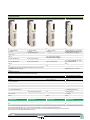
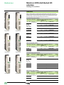
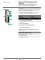
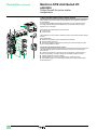
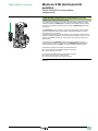
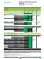
1
IP 20 distributed
inputs/outputs
Modicon STB
Catalogue
May
2013
Unity Pro
Advantys
Unity Pro
How to find the
“Automation and Control” products
Catalogues
Essential guides
Complete product ranges
Selection of the top selling
products
General contents
Modicon distributed I/O solutions selection guide. . . . . . . . . . . . . . . . . . . page 2
bb Open and modular system ....................................................................... page 4
bb Network interface modules
Selection guide . . . . . . . . . . . . . . . . . . . . . . . . . . . . . . . . . . . . . . . . . . . . . . page 16
vv References................................................................................................ page 22
bb Internal bus expansion modules, CANopen expansion module,
auxiliary power supply module
Selection guide . . . . . . . . . . . . . . . . . . . . . . . . . . . . . . . . . . . . . . . . . . . . . . page 30
vv References................................................................................................ page 34
bb Power distribution modules
Selection guide . . . . . . . . . . . . . . . . . . . . . . . . . . . . . . . . . . . . . . . . . . . . . . page 36
vv References................................................................................................ page 42
bb Digital I/O modules
Selection guide . . . . . . . . . . . . . . . . . . . . . . . . . . . . . . . . . . . . . . . . . . . . . . page 44
vv References................................................................................................ page 56
bb Analog I/O modules
Selection guide . . . . . . . . . . . . . . . . . . . . . . . . . . . . . . . . . . . . . . . . . . . . . . page 58
vv References................................................................................................ page 66
bb Application-specific modules
Selection guide . . . . . . . . . . . . . . . . . . . . . . . . . . . . . . . . . . . . . . . . . . . . . . page 68
vv Parallel interface module for TeSys U and
TeSys Quickfit applications............................................................................. page 74
vv Counter module......................................................................................... page 78
vv HART multiplexer solution......................................................................... page 81
bb Configuration software
Selection guide . . . . . . . . . . . . . . . . . . . . . . . . . . . . . . . . . . . . . . . . . . . . . . page 82
vv References................................................................................................ page 90
bb Combinations
vv With Momentum 171CBB97030 processor................................................ page 96
vv With Magelis operator dialogue terminals................................................ page 100
vv With STB I/O modules and Telefast ABE7 wiring system......................... page 102
bb Phaseo regulated switch mode power supplies
vv References.............................................................................................. page 107
bb Compatibility with sensors
vv OsiSense XU photo-electric sensors....................................................... page 108
vv OsiSense XS inductive proximity sensors.................................................page 110
bb Technical appendices
vv Certifications for automation products......................................................page 112
vv Power consumption table.........................................................................page 114
bb A dedicated services offer for your installed base
vv Operation services....................................................................................page 116
vv Modernisation services.............................................................................page 117
vv Customization services.............................................................................page 117
bb How to find products ?
vv Search, visualize and download...............................................................page 118
vv Access product references with adapted tools......................................... page 120
vv Compare, select and compile.................................................................. page 122
vv Check the product status, design your equipment................................... page 123
bb Product reference index........................................................................ page 124
1
Selection guide
Type of splitter box and module
Modicon distributed I/O solutions
Monobloc IP 67 I/O splitter boxes
Modicon ETB
Available buses and
networks
Ethernet Modbus TCP/IP
EtherNet/IP
Max. number per connection point
Discrete I/O
Modularity
Splitter box with 16 configurable I/O, 16 I, 12 I + 4 O, or 8 I +8 O
Input voltage
24 V c
Output voltage
24 V c
Analog I/O
–
Application-specific I/O
–
–
I/O connection
M12 connectors
Type of housing
Plastic
Type of module
ETB1Eppp
Pages
Please consult the catalogue pages on our website www.schneider-electric.com
2
Monobloc IP 20 distributed I/O
Optimum IP 20 distributed I/O
Modular IP 20 distributed I/O
Modicon Momentum
Modicon OTB
Modicon STB
Ethernet Modbus TCP/IP
Modbus Plus
Fipio
InterBus
Profibus DP
DeviceNet
Ethernet Modbus TCP/IP
CANopen
Modbus (RS 485)
Ethernet Modbus TCP/IP
EtherNet/IP
CANopen
Modbus Plus
Fipio
InterBus
Profibus DP
DeviceNet
1 sub-base with 1 CPU or 1 communication module
1 interface module + 7 Twido expansion modules
1 NIM (Network Interface Module) + 32 I/O modules
Sub-base with 16 I, 32 I, 8 O, 16 O, 32 O, 10 I/8 O,
16 I/8 O, 16 I/12 O and 16 I/16 O
12 I/8 O (interface module)
8 I, 16 I, 32 I, 8 O, 16 O, 32 O, 4 I/4 O and 16 I/8 O
(expansion modules)
Module with 2 I, 4 I, 6 I, 16 I, 2 O, 4 O, 6 O or 16 O
24 V c, 120 V a and 230 V a
24 V c
24 V c, 115 V a and 230 V a
24 V c V, 120 V a and 230 V a and relay
24 V c and relay
24 V c, 115/230 V a and relay
8 I, 16 I or 4 O voltage/current sub-bases
Sub-base with 4 thermocouple or probe inputs
2 I, 4 I, 8 I, 1 O, 2 O, 2 I/1 O and 4 I/2 O
(expansion modules)
voltage/current, thermocouple or
temperature probe
Modules with 2, 4 or 8 inputs and 1 or 2 outputs
(voltage/current)
Sub-base with 2 thermocouple or probe inputs
10 kHz/200 kHz 2-channel counter sub-base
Integrated in interface module:
- Two 5 kHz/20 kHz channels
- 2 PWM function channels
Counter module with one 40 kHz channel
6 I/3 O 120 V a sub-base with 1 Modbus port
–
Parallel interface modules for TeSys Quickfit and
TeSys U motor starters, integrated connection for
third-party CANopen products
Screw or spring-type removable terminal blocks
Removable screw terminal block (interface module)
Removable screw terminal block, non-removable
spring-type terminal block and HE 10 connector
(expansion modules)
Removable screw or spring-type connectors,
Telefast connectors
OTB1p0DM9LP
STBppp
Plastic
170ADp
Please consult the catalogue pages on our website www.schneider-electric.com
3
Presentation
Modicon STB distributed I/O
solution
Open and modular system
Presentation
To meet the needs of machine manufacturers and users, automation architectures
have been decentralized while delivering performance close to that of centralized
systems.
Architectures based around islands installed as close to the machine as possible
reduce the time and cost of wiring for sensors and actuators, while increasing
system availability.
Modicon STB island example
The Modicon STB distributed I/O system is an open, modular input/output system
and makes it possible to design industrial automation islands managed by a master
controller via a bus or communication network.
These islands can be used to connect:
bb TeSys U or TeSys T motor starters
bb Altivar variable speed drives
bb FTB IP 67 distributed I/O
bb OsiSense rotary encoders
bb Magelis HMI terminals
bb Approved third-party products via the CANopen bus: Bosch, Festo,
Parker valves, Balluff linear encoders, etc. (1)
Advantys software guides users through the design phase, start-up, and even
maintenance of the system. This single software package covers the Modicon STB,
OTB, FTB, and FTM ranges.
Colour code
Module type
NIM network interface
EOS/BOS island expansion
CANopen expansion
24 V c digital inputs
24 V c power distribution
24 V c digital outputs
115 V a or 230 V a digital current inputs
115/230 V a power distribution
115/230 V a digital current outputs
Digital relay outputs
TeSys U, TeSys Quickfit interface module
and counter module
Analog inputs
Analog outputs
The island components are electronic modules mounted on one or more DIN rails.
These clusters of modules, known as segments, carry a bus from beginning to end of
each island. The island bus provides power distribution, signal sensing, and power
management to all compatible modules, in the form of a wiring management system.
The Modicon STB I/O family can be divided into 2 groups of modules:
bb Basic modules: A set of low-cost modules, with simplified operating modes.
bb Standard modules: An extended offer of I/O modules, with additional functions:
configurable parameters, extended operating modes.
The basic range comprises:
bb PDM power distribution modules (24 V c and 115/230 V a)
bb I/O modules:
vv Digital I/O (24 V c)
vv Analog I/O (10-bit resolution).
The standard range comprises:
bb NIM modules: network interfaces
bb PDM power distribution modules (24 V c and 115/230 V a)
bb I/O modules:
vv Digital I/O (24 V c and 115/230 V a)
vv Analog I/O (10, 12, and 16-bit resolution)
vv Relay outputs (24 V c coil and 24 V c or 115/230 V a contact)
bb Application-specific module: counter module, HART multiplexer
bb Dedicated module: for TeSys U and TeSys Quickfit applications
bb EOS end of segment and BOS beginning of segment modules.
bb External equipment support module on CANopen expansion
Standard and basic modules can be combined on the same island. Combining them
in this way allows a wide range of functions as shown in the table on page 15.
The sensors and actuators are connected to the I/O modules via removable
screw-type or spring-type terminals (2).
Standard Modicon STB I/O modules are hot-swappable, provided the network
interface modules are also standard type.
Modicon STB distributed I/O islands have a protection rating of IP 20. For
installations in production workshops, they must be incorporated in protective
casings with at least an IP 54 rating (in compliance with IEC 60950 or NEMA 250).
See page 112.
(1) For more information, please visit our website at www.schneider-electric.com.
(2) For greater ease of wiring and to free up space in the enclosure, it is possible to combine
Modicon STB 16-channel digital I/O modules with Modicon Telefast ABE7 prewired or adaptation
sub-bases.
4
Modicon STB distributed I/O
solution
Description
Open and modular system
Modicon STB modules
The Modicon STB module references allow you to acquire, under a single reference,
the following items:
bb A module
bb Its base
bb The appropriate screw and/or spring-type connectors.
The table below presents the contents of Modicon STB modules and the usual
form for their references.
These references are used in the descriptions contained in this catalogue
(functions, characteristics, etc).
The module contents, optional parts and replacement parts are detailed on the
“References” pages of each module.
Content
Reference
NIM network interface
Module
Module, power supply screw-type
connectors and spring-type connectors
(base not required), bus termination,
mini CD-Rom documentation (1)(2)
STBNpppppp
Power distribution module
(PDM)
Base, module,
screw-type and spring-type connectors
STBpppppppK
Base, module, screw-type connectors
STBDDp37p5KS
Base, module, spring-type connectors
STBDDp37p5KC
Module (3)
STBDDp37p5
Hart multiplexer
STBAHI8321KC
Base, module, spring-type connectors
STBEHC3020KC
Digital I/O
(except for 16-channel)
Analog I/O
EOS and BOS
island bus extension
CANopen bus extension
Base
Auxiliary power supply
TeSys U and
TeSys Quickfit interface
Module
16-channel digital I/O
Screw-type.
connectors
Counter
Spring-type.
connectors
(1) NIM DeviceNet network interface module STBNDNpppp: 5-way screw-type and spring‑type
removable terminal blocks (fieldbus link) should be ordered separately (see page 22).
(2) An English-language mini-CD-ROM supporting the user documentation, a label template
and one exchange file per network type The user documentation is also available on our
website, www.schneider-electric.com.
(3) For use with the Modicon Telefast ABE7 prewired or adaptation system:.
- STBXBA3000 base to be ordered separately (see page 56) .
- Telefast ABE7 base and connection accessories to be ordered separately .
(see page 103).
5
Composition
Modicon STB distributed I/O
solution
Open and modular system
Composition of a Modicon STB island
A Modicon STB island is made up of one or more segments comprising PDM power
distribution modules and I/O modules.
An island starts with a NIM network interface module and ends with a bus terminator
supplied with the NIM module.
An island can be made up of a single segment or a primary segment and up to
6 expansion segments.
The island segments are chained by EOS (End Of Segment) and BOS (Beginning Of
Segment) internal bus expansion modules. See page 9.
On each segment:
bb The PDMs must be placed immediately to the right of the network interface
modules or expansion modules.
bb The I/O modules are placed to the right of the PDM module supplying them with
power.
bb Each module (with the exception of the NIM network interface module) is held in a
fixing base on the DIN rail.
Three module and base widths are possible. On the DIN rail, the overall width
needed for a segment is the sum of widths of the network interface module, the
bases and any bus termination.
The bases ensure the continuity of the internal bus, the auto-addressing of the
modules, and the separated and isolated distribution of the internal power supplies,
actuators (outputs) and sensors (inputs).
The advantages of this arrangement are:
bb Unplugging modules:
vv When switched off (cold swap), all modules can be unplugged very quickly.
vv When switched on (hot swap), I/O modules can be unplugged provided the
network interface module is the standard type.
bb Output power supply independent of inputs: For example, if an output power
supply is cut by a Preventa module, the inputs are still managed.
bb Immunity of inputs: For example, the closing of power contactors (controlled by
outputs) does not disturb analog input measurements.
NIM network interface module:
This module manages communications on the island bus. It acts as a gateway for
exchanges with the fieldbus or network master.
Different NIM interface modules (standard type only) are available for the following
main fieldbuses or local area networks:
bb Ethernet Modbus TCP/IP: single port or double port NIM modules.
bb EtherNet/IP, InterBus, CANopen, Modbus Plus, Fipio, Profibus DP and
DeviceNet.
6
Configurations
Modicon STB distributed I/O
solution
Open and modular system
Standard Modicon STB configurations
Single segment
With a standard NIM network interface module it is possible to create an island with
only one segment (“single” segment) comprising up to 32 I/O modules (excluding PDM
power distribution modules, NIM network interface module, bus termination and
auxiliary power supply).
1 2
3
4
5
2
3
4
5
6
32 I/O modules max.
Single segment standard Modicon STB
In the example above, the single segment comprises:
1 STBNpp2p1p: A standard NIM (Network Interface Module). This is placed at the
beginning of the primary segment. Each island must have only one NIM module
(1).
2 STBPDT210pK: A basic (2) or standard (3) PDM (Power Distribution Module).
This is installed immediately to the right of the NIM and distributes the 115/230 V
a voltage to the I/O modules powered with AC.
3 STBDApK: Digital (Discrete) I/O modules with AC power.
4 STBPDT310pK: A basic (2) or standard (3) PDM power distribution module. This
is installed after all the a 115/230 I/O modules. It distributes the 24 V c voltage
to the I/O modules powered with DC.
5 STBAVpK, STBACpK, STBDDpK: Digital or analog I/O modules powered
with DC.
6 STBXMP1100: A bus termination plate (4).
(1) The auxiliary power supply module STBCPS2111K (not shown) supplies a 5 V c 1.2 A logic
power supply in addition to that of the NIM module. This module is used when the island segment
I/O modules draw a current higher than 1.2 A. It must be combined with a PDM power distribution
module.
(2) Basic PDMs isolate the internal 5 V c logic power supply and the common 24 V c power
supply for the inputs/outputs.
(3) Standard PDMs isolate the internal 5 V c logic power supply and the separate 24 V c power
supplies for the inputs/outputs.
(4) Supplied with the NIM network interface module.
7
Configurations (continued)
Modicon STB distributed I/O
solution
Open and modular system
Standard Modicon STB configurations (continued)
Primary segment with expansion segments
The island bus can support the primary segment with up to 6 expansion segments
(7 segments in all).
A standard NIM network interface module supports up to 32 I/O modules (excluding
power distribution modules, network interface modules, bus termination, auxiliary
power supplies, and EOS/BOS bus expansion modules).
1 2
3
4
7
5 2
3
2
3
4
7
5 2
3
6
15 m max. with 32 I/O modules or external devices
Standard Modicon STB with 3 segments
The segments in the above Modicon STB configuration comprise:
1 STBNpp2p1p: A standard NIM network interface module. This is placed at the
beginning of the primary segment. Each island must have only one NIM module.
2 STBPDTp100K: A standard 24 V c or 115/230 V a PDM power distribution
module. This is installed immediately to the right of the NIM and distributes the
24 V c or 115/230 V a, according to the type of I/O modules located on the right.
3 STBAVp, STBACp, STBARp, STBDDp, STBDAp and STBDRp: Digital (Discrete)
I/O modules with DC or AC power. They are placed immediately to the right of the
PDM power distribution module.
4 STBXBE1100K: EOS bus expansion module. This is always installed in the
farthest right slot in the primary or expansion segment, and extends the island
bus to another segment.
5 STBXBE1300K: BOS bus expansion module. This is installed at the beginning of
each expansion segment (1).
6 STBXMP1100: An island bus termination plate (2).
7 STBXCA100p: Island bus extension cables.
(1) The BOS bus expansion module STBXBE1300K provides a 5 V c 1.2 A logic power supply,
from an external 24 V c power supply. This power supply is distributed to island segment modules
located on its right.
(2) Supplied with the NIM network interface module.
8
Configurations (continued)
Modicon STB distributed I/O
solution
Open and modular system
Standard Modicon STB configurations (continued)
CANopen expansion module - Device Integration
The CANopen expansion module STBXBE2100K can be used to connect, at the end
of the segment, external CANopen devices such as:
bb Modicon FTB IP67 I/O, in plastic or metal casing
bb ATV31C/312/32/61/71 variable speed drives (1)
bb Festo CPV-CO2 electropneumatic valves
bb Parker P2M2HBVC11600 electropneumatic valves
bb Balluff Micropulse BTL5 linear encoders
bb OsiSense absolute rotary encoders
bb TeSys U and TeSys T starter-controllers
bb Scaime eNod4-T weighing module, etc. (2).
A standard NIM network interface module supports up to 32 I/O modules and
external CANopen devices (excluding power distribution modules, network interface
modules, EOS/BOS bus expansion modules and CANopen expansion modules).
The number of external CANopen devices depends on the standard NIM network
interface module:
bb Standard CANopen and InterBus NIM modules: Up to 7 external CANopen
devices.
bb Standard Ethernet Modbus TCP/IP single port or double port, EtherNet/IP,
Modbus Plus, Fipio and Profibus DP NIM modules: Up to 12 external CANopen
devices.
The data rate of the internal bus is set to 500 Kbps with the Advantys STBSPU1ppp
configuration software. This speed applies to all Modicon STB modules and external
devices.
1 2 3
4 5
6
7 2
8 9 10
11
13
14
12
External CANopen
devices
15 m max.
12/60 m max. (3)
32 I/O modules or external devices
Daisy chaining of external CANopen devices on an island expansion segment
The island bus in the above example comprises:
1 STBNpp2p1p: A standard NIM network interface module.
2 STBPDT3100K: A standard 24 V c PDM power distribution module.
3 STBEHC3020KC: 1-channel counter module.
4 STBDDI3420K: Digital input modules.
5 STBXBE1100K: EOS bus expansion module (end of segment).
6 STBXCA100p: Island bus extension cable.
7 STBXBE1300K: BOS bus expansion module (beginning of segment).
8 STBACpK: Analog I/O modules.
9 STBXBE2100K: CANopen expansion module (max. 12 devices per island).
10 STBXMP1100: Island bus termination plate.
11 TSXCANCAppp: CANopen cable.
12 Any CANopen external device belonging to the Advantys software library, such
as for example:
13 Modicon FTB IP67 I/O.
14 ATV312 variable speed drive.
(1) ATV32 variable speed drives will be integrated to Modicon STB during the 2nd semester
2013.
(2) To obtain the latest list of approved equipment on the CANopen extension, please consult our
Customer Care Centre or our website, www.schneider-electric.com.
To validate a new product, please consult our Customer Care Centre.
(3) Total length of CANopen expansion segment: 12 m as standard, 60 m in accordance with the
CAN wiring rules described in the CANopen setup document no. 31010857 (in English) available
on our website, www.schneider-electric.com.
9
Configurations (continued)
Modicon STB distributed I/O
solution
Open and modular system
Standard Modicon STB configurations (continued)
Application-specific module for TeSys U and TeSys Quickfit startercontrollers
The STBEPI2145K parallel interface module is used to connect TeSys U
starter‑controllers and TeSys Quickfit motor starters.
The TeSys U starter-controller must be equipped with the LUFC00 parallel
communication module.
The characteristics and advantages of this solution are:
bb Control of both directions of motor travel
bb Simple wiring
bb Configuration with Advantys software
bb Hot swapping possible (see page 15).
1
1
8
7
5
9
2
2
3 4
6
TeSys U connected to a standard Modicon STB
9
3 4
4
Reversing TeSys Quickfit connected to a
standard Modicon STB
The island bus in the above examples comprises:
1 Modicon STB primary island segment.
2 STBNpp2p1p: A standard NIM network interface module.
3 STBEPI2145K: Parallel interface module for TeSys U starter-controllers and
TeSys Quickfit motor starters (1).
4 LU9Rpp: Cable with one RJ45 connector at each end.
5 STBLUFC00: Modicon parallel communication module.
6 TeSys U starter-controller.
7 LAD9AP3pp: TeSys Quickfit control connection module.
8 TeSys Quickfit reversing motor starter.
9 STBXMP1100: A bus termination plate (2).
(1) Refer to the “Motor-starter solutions. Control and protection components” catalogue.
(2) Supplied with the NIM network interface module.
10
Configurations (continued)
Modicon STB distributed I/O
solution
Open and modular system
Standard Modicon STB configurations (continued)
CANopen expansion module for TeSys U and TeSys T starter-controllers
The CANopen expansion module STBXBE2100K is used to connect TeSys U and
TeSys T starter-controllers, via a CANopen tap-off junction.
The TeSys U starter-controller must be equipped with the LULC08 CANopen
communication module.
The characteristics and advantages of this solution are:
bb Advanced process control, such as reading current data, detailed diagnostics,
remote reset, etc.
bb Configuration with SoMove software
bb Hot swapping possible (see page 15).
1
6
2
3
7
8
4
4
4
5
CANopen daisy chaining of TeSys T and a TeSys U tap link on a standard Modicon STB
The island bus in the above example comprises:
1 Modicon STB primary island segment.
2 STBNpp2p1p: A standard network interface module.
3 STBXBE2100K: CANopen expansion module (max. 12 devices per island).
4 TSXCANCAppp: CANopen cable.
5 VW3CANTAP2: CANopen tap-off junction.
6 LULC08 CANopen communication module .
7 TeSys U (LUBpp) starter-controller with an advanced control unit (LUCB/C/D).
8 TeSys T motor management system (LTMRppC) with CANopen communication
port.
11
Configurations (continued)
Modicon STB distributed I/O
solution
Open and modular system
Standard Modicon STB configurations (continued)
TeSys U starter-controller as preferred module
The island bus can support TeSys U starter-controllers as preferred modules
(installation between 2 island segments).
TeSys U starter-controllers must be equipped with a Modicon STB LULC15 serial
communication module.
The characteristics and advantages of this solution are:
bb Advanced process control (integrated in the Advantys software), such as reading
current data, detailed diagnostics, remote reset, etc.
bb Configuration with Advantys software
bb Hot swapping not possible (see page 15).
1
6
6
5
2
34
9
7
5
8
10
11
15 m max. with 32 I/O modules or
external devices
TeSys U as preferred module on a standard Modicon STB
The island bus in the above example comprises:
1 Modicon STB primary island segment.
2 STBNpp2p1p: A standard NIM network interface module.
3 Removable screw connector for connection of an external 24 V c power supply,
required for the TeSys U LULC15 communication module.
4 STBXBE1100K: End of segment, used to connect the preferred TeSys U
modules.
5 Angled cable with an island bus extension cable connector at each end, providing
the bus signals and the internal power supply (LU9RCDpp).
6 Modicon STB LULC15 serial communication modules
7 TeSys U starter-controller (LUBpp) with an advanced control unit (LUCB/C/D).
8 TeSys U starter-controller (LUBpp) with a multifunction control unit (LUCM).
9 Angled cable with an island bus extension cable connector at each end, providing
the bus signals and the internal power supply (LU9RDDpp).
10 STBXBE1300K: Beginning of segment.
11 STBXMP1100: A bus termination plate (1).
(1) Supplied with the NIM network interface module.
12
Modicon STB distributed I/O
solution
Configurations (continued)
Open and modular system
Example of control system configuration
NIM network interface modules STBNpp2p1p, located at the beginning of each
island, are gateways for exchanging data between the network or bus master PLC
and the Modicon STB automation island.
Standard NIM STBNpp2p1p modules can be used to configure and address the
installation external devices. These settings are stored in the module’s internal RAM
or Flash memory. Optionally, they can be saved to the 32 Kb removable SIM card
STBXMP4440 (except for the address of the network connection point) to duplicate
the configuration from one island to another.
1
8
7
2
(1)
4
5
6
9
5
6
11
12
13
14
15
10
3
The control system configuration in the above example comprises:
1 Modicon M340/Premium/Quantum automation platform.
2 24 V c external power supply.
3 HMI terminal with Magelis XBT, XBTG, XBTGT type Modbus link
(see link cables on page 101).
4 NIM network interface module.
5 PDM power distribution module.
6 I/O modules.
7 Second STB segment.
8 Another control system.
9 Parallel interface module for TeSys U and TeSys Quickfit starter-controllers.
10 Configurable Preventa XPS MC safety controller connected on the power supply
to the outputs of the power distribution module STBPDTp100K.
11 ATV 312 variable speed drive.
12 Festo solenoid valves.
13 Modicon FTB IP67 I/O.
14 Parker solenoid valves.
15 TeSys U starter-controller.
(1) In the above example, the 24 V c power supplies for the PDM power distribution module and
the BOS bus expansion module are not shown. See pages 39 and 33 respectively.
13
Functions
Modicon STB distributed I/O
solution
Open and modular system
Basic/standard Modicon STB functions
The table below sets out the main functions of the basic and standard Modicon STB
ranges:
I/O modules
Modicon STB
Max. number of I/O modules
Basic
Standard
Removable terminals
Mechanical keying pin
Cold swapping
Hot swapping
(1)
(1)
Separate power supply to sensors and actuators
(2)
(2)
Built-in electronic protection of inputs and outputs
Electronic protection of power supply provided by
Modicon STB for the sensors
Protection of power supplies by built-in removable fuse
Status LEDs
Compatible with all types of network interface module
CANopen expansion - Device Integration
Compatible with local HMI (Magelis)
Default configuration
Assistance with design, start-up, maintenance, power
consumption, auto mapping using Advantys software
Configurable I/O parameters
Built-in reflex functions
Removable memory card (1)(8)
Advanced diagnostics
Internal software (firmware) update
Network interface
modules (NIM)
Power distribution
modules (PDM)
Standard
32
Basic
Standard
(3)
(4)
38
–
–
–
–
–
10
100
84
84
(5)
(7)
85
89
22
86
21
(1)
(1)
(1)
Function available
See page
6
to 9
–
53
6
6, 15
Function not available
Not applicable
(1) Requires the use of a standard NIM module.
(2) Requires the use of standard PDM modules.
(3) Basic PDM: One 5 A fuse for the inputs and outputs.
(4) Standard PDM: One 5 A fuse for the inputs and one 10 A fuse for the outputs.
(5) Requires the use of Advantys software, acquired separately or via the Unity Pro software.
(6) In offline mode only.
(7) In offline and online modes.
(8) For assistance with the island internal settings. Simplifies faulty device replacement (FDR)
and copying of the island settings.
14
Functions (continued)
Modicon STB distributed I/O
solution
Open and modular system
Hot swapping
When a module on the standard type Modicon STB island is unplugged under power,
the behaviour of the other modules depends on the parameter settings of standard
type I/O modules :
bb Mandatory or optional module
bb Configured fallback type per channel.
Swapping a module
Basic input
Standard input optional
Standard input mandatory
Basic output
Standard output optional
Standard output mandatory
Power distribution module (PDM)
NIM network interface
Behaviour of the other modules (1)
The other outputs remain operational
The other outputs remain operational (1)
Fallback of other outputs according to configuration (1)(2)
The other outputs remain operational
The other outputs remain operational (1)
Fallback of other outputs according to configuration (1)(2)
Prohibited
Prohibited
Operating environment
Modicon STB devices comply with the following certifications (3):
bb UL
bb CSA
bb C-Tick
bb GOST
bb CE
bb FM (class 1, division 2, groups A, B, C, D T4A @ 70°C).
bb ATEX 3G (II 3 G Ex nA IIC T4 Ta=0...60 °C) (4).
They benefit from merchant navy certifications issued by shipping classification
societies:
bb ABS (USA)
bb BY (France)
bb DNV (Norway)
bb GL (Germany)
bb LR (Great Britain)
bb RINA (Italy)
bb RMRS (IEC, pending)
They are designed for use in industrial environments of pollution class 2, in
applications of overvoltage category II (as defined in publication IEC 60664-1) and at
altitudes of up to 2000 m, without reduction in load.
Protection enhanced with a coating is provided on request, for use in harsh industrial
environments (see page 117).
(1) Fallback level set by the Advantys STBSPU1ppp software on standard I/O modules with a
standard NIM. .
The STBSPU1ppp software cannot be connected on basic NIM modules.
(2) The fallback state is adjustable on standard output modules:
-- Fallback to 0 for digital modules
-- Fallback to 1 for digital modules
-- Fallback to any value on analog outputs
-- Hold last value on digital and analog outputs
(3) Certifications for all automation products (see page 112).
(4) For ATEX zones not covered by this specification, Schneider Electric offers a solution under
the CAPP program (Collaborative Automation Partner Program). Please consult our Customer
Care Centre.
Note: Limiting supply voltages. The supply voltages for NIM modules, STBXBE1300K,
STBXBE1100K, STBCPS2111K, STBPDT3100K, as well as all the external supply voltages, are
limited as follows for the ranges of operating temperatures below:
-- for the range -25...0°C , the supply voltage range is 20.4...30 V c
-- for the range 0...60°C , the supply voltage range is 19.2...30 V c
-- for the range 60...70°C , the supply voltage range is 19.2...26.5 V c.
15
Selection guide
Modicon STB distributed I/O
solution
Network interface modules
Applications
Data exchange between master PLC and Modicon STB island I/O modules
Bus or network type
Ethernet Modbus TCP/IP, dual port
Bus or network
Structure
Type
Industrial LAN
Topology
Standard, daisy chain, daisy-chain loop
Compliance with standards
IEEE 802.3
Standard
Physical interface
10/100 BASE-T, half/full duplex
10 BASE-T
Data rate
10/100 Mbps
10 Mbps
Medium
Double shielded twisted pair via Ethernet ConneXium cabling system
Configuration
Features of NIM module
(2)
Interface connectors
Number of devices (1)
256 max. per segment, unlimited with switches
Maximum length
100 m according to 802.3 standard, > 100 m with ConneXium cabling system
Number of I/O modules per
Modicon STB island (1)
Standard NIM: 32 modules max. on 1 primary segment and 6 expansion segments max.
Supply voltage
24 V c not isolated (19.2…30 V) (3)
Input current
550 mA
Logic power supply (4)
Output voltage: 5.25 V c ± 0.21 %
Nominal output current: 1.2 A (5)
CANopen devices supported (6)
12 devices max.
Bus or network port
2 x Female RJ45 (embedded switch)
RS 232 port (configuration,
dialogue with Magelis and
firrmware update)
HE 13, 8-way female
Services used
- Embedded Web (configuration, diagnostics
and access to variables )
- Modbus TCP/IP
- SNMP agent
- DHCP and BOOTP client services
Operating temperature, horizontal mounting
Standard NIM: -25…70°C (7)(8)
Type of NIM module
STBNIP2311
Standard
Basic
Page
22
(1) One Modicon STB island corresponds to 1 device on the bus or the network.
(2) See table of functions provided by the basic and standard Modicon STB ranges (page 15).
(3) Use a 24 V c external SELV (Safety Extra Low Voltage) power supply, rated at minimum 700 mA current output.
(4) Provides logic power to all I/O modules on the primary segment.
(5) 0.575 A for operating temperatures between 60 and 70°C.
(6) Connection via the STBXBE2100K CANopen bus expansion module.
More technical information on www.schneider-electric.com
16
Ethernet Modbus TCP/IP
430 mA
Female RJ45
- Embedded Web (configuration, diagnostics
and access to variables)
- Modbus TCP/IP
- SNMP agent
- DHCP and BOOTP client services
STBNIP2212
Data exchange between master PLC and Modicon STB island I/O modules
EtherNet/IP
CANopen bus
Industrial LAN
CAN fieldbus
Standard
IEEE 802.3
CIA DS-301
10/100 BASE-T, half/full duplex
ISO 1198
10/100 Mbps
10 kbps…1 Mbps depending on bus length
Double shielded twisted pair via Ethernet ConneXium cabling system
Double shielded twisted pair
256 max. per segment, unlimited with switches
127 slaves
100 m according to 802.3 standard, > 100 m with ConneXium cabling system
From 30 m (1 Mbps) to 5000 m (10 kbps)
Standard NIM: 32 modules max. on 1 primary segment and 6 expansion
segments max.
Standard NIM: 32 modules max. on 1 primary segment and 6 expansion
segments max.
24 V c not isolated (19.2…30 V) (3)
430 mA
Output voltage: 5.25 V c ± 0.21 %
Nominal output current: 1.2 A (5)
12 devices max.
7 devices max.
Female RJ45
9-way male SUB-D
HE 13, 8-way female
- Embedded Web (configuration, diagnostics and access to variables)
- SNMP agent
- DHCP and BOOTP client services
- Process Data Object (PDO)
- Service Data Object (SDO)
- Network management (NMT)
Standard NIM: -25…70°C (7)(8)
STBNIC2212
STBNCO2212
22
(7) Standard NIM modules:.
- For -25...0 °C range, the supply voltage range is 20.4...30 V c
- For 0...60 °C range, the supply voltage range is 19.2...30 V c
- For 60...70 °C range, the supply voltage range is 19.2...26.5 V c
(8) When using the segment in extended temperature range (-25...70°C), the power consumption can be only calculated using Advantys or Unity Pro software.
More technical information on www.schneider-electric.com
17
Selection guide (continued)
Modicon STB distributed I/O
solution
Network interface modules
Applications
Bus or network type
Bus or network
Structure
Data exchange between master PLC and Modicon STB island I/O modules
Modbus Plus
Fipio
Type
Industrial LAN compliant with the Modbus
Plus standard
Open industrial fieldbus compliant with the
FIP standard
Compliance with standards
modbus.org
EN 50170,Vol 3, Parts1-3, 2-3, 3-3, 5-3, 6-3
and 7-3
Physical interface
Modbus Plus standard
FIP standard
Data rate
1 Mbps
1 Mbps
Twisted pair
Shielded twisted pair
Number of devices
(1)
32 per segment
64 for all segments
32 per segment
128 max. for all segments
Maximum length
450 m per segment
1800 m with 3 repeaters
1000 m per segment
Number of I/O modules per
Modicon STB island (1)
Standard NIM: 32 modules max. on 1 primary segment and 6 expansion segments maxi
Input current
430 mA
Supply voltage
24 V c not isolated (19.2…30 V) (3)
Logic power supply (4)
Output voltage: 5.25 V c ± 0.21 %
Nominal output current: 1.2 A (5)
CANopen devices supported (6)
12 devices max.
Bus or network port
9-way female SUB-D
RS 232 port (configuration,
dialogue with Magelis and
firrmware update)
HE 13, 8-way female
Medium
Configuration
Features of NIM module
(2)
Connector type
Services used
- Global data
- Peer-to-peer
- Peer Cop
Operating temperature, horizontal mounting
Standard NIM: -25…70°C (7)(8)
Type of NIM module
STBNMP2212
Standard
Basic
Page
22
(1) One Modicon STB island corresponds to 1 device on the bus or the network.
(2) See table of functions provided by the basic and standard Modicon STB ranges (page 15).
(3) Use a 24 V c external SELV (Safety Extra Low Voltage) power supply, rated at minimum 700 mA current output.
(4) Provides logic power to all I/O modules on the primary segment.
(5) 0.575 A for operating temperatures between 60 and 70°C.
(6) Connection via the STBXBE2100K CANopen bus expansion module.
More technical information on www.schneider-electric.com
18
9-way male SUB-D
- Periodic I/O exchanges
- Point-to-Point message
- Use of standard profiles (FRD/FSD/FED)
STBNFP2212
Data exchange between master PLC and Modicon STB island I/O modules
InterBus
Profibus DP
DeviceNet
InterBus industrial field bus (generation 4)
Profibus DP V.0 industrial field bus
Network compliant with v.2.0 of the Open DeviceNet
Vendor Assoc. (ODVA)
INTERBus Club
DIN 19245, Parts 1 and 3
Open DeviceNet Vendors Association
Isolated RS 485
RS 485
–
500 kbps
9.6 kbps…12 Mbps
125, 250 or 500 kbps
Shielded twisted pair
Twisted pair
512 slaves max. with 254 bus terminal modules max
125 slaves
64 slaves
400 m per segment of the remote bus
12.8 km for the remote bus
50 m for the installation remote bus
1200 m (9.6 kbps)
4800 m with 3 repeaters
200 m (12 Mbps)
800 m with 3 repeaters
1200 m
Standard NIM: 32 modules max. on 1 primary segment and 6 expansion segments max.
430 mA
24 V c not isolated (19.2…30 V) (3)
Output voltage: 5.25 V c ± 0.21 %
Nominal output current: 1.2 A (5)
7 devices max
12 devices max.
Input: 9-way male SUB-D
Output: 9-way female SUB-D
9-way female SUB-D
5-way male connector
- Slave configuration
- Configuration control
- Read/write slave I/O data
- Diagnostics on Profibus frames
- DeviceNet Object (Class ID3)
- Connection Object (Class ID5)
- Island Bus Object (Class ID101)
STBNDP2212
STBNDN2212
HE 13, 8-way female
- Implicit exchange of process data
- Logical addressing
- Diagnostics
Standard NIM: -25…70°C (7) (8)
STBNIB2212
22
(7) Standard NIM modules:.
- For -25...0 °C range, the supply voltage range is 20.4...30 V c
- For 0...60 °C range, the supply voltage range is 19.2...30 V c
- For 60...70 °C range, the supply voltage range is 19.2...26.5 V c
(8) When using the segment in extended temperature range (-25...70°C), the power consumption can be only calculated using Advantys or Unity Pro software.
More technical information on www.schneider-electric.com
19
Presentation
Modicon STB distributed I/O
solution
Network interface modules
Presentation
1
The range of NIM network interface modules comprises 9 standard NIM modules.
Each module is dedicated to a specific network or bus:
Network or bus
Ethernet Modbus TCP/IP, dual port
Ethernet Modbus TCP/IP
EtherNet/IP
CANopen
Modbus Plus
Fipio
InterBus
Profibus DP
DeviceNet
2
3
Standard network interface module
STBNIP2311
STBNIP2212
STBNIC2212
STBNCO2212
STBNMP2212
STBNFP2212
STBNIB2212
STBNDP2212
STBNDN2212
All NIM network interface modules are supplied with two removable terminal power
supply connectors: one screw-type and one spring-type.
Power supply for network interface modules
The NIM network interface module is supplied by an external 24 V c power supply.
It converts this voltage to 5 V c to provide the 5 V c logic power to the I/O modules
of the island’s primary segment.
4
The 5 V c logic power supply integrated in the NIM module provides a maximum
current of 1.2 A (operation in extended temperature ranges, see page 22).
This current can be increased by adding an STBCPS2111K auxiliary power supply
that also provides a maximum current of 1.2 A (operation in extended temperature
ranges, see page 34).
The STBCPS2111K auxiliary power supply module must be used with an
STBPDTp10pK power distribution module placed after it.
5
The 5 V c logic power for the I/O modules in the expansion segments is provided by
the STBXBE1300K BOS bus expansion module placed at the beginning of these
segments. In the same way that an STBCPS2111K auxiliary power supply module
can be added for the primary segment, if the required current exceeds 1.2 A (see
page 34).
6
7
8
9
10
20
Modicon STB distributed I/O
solution
Description
Network interface modules
Description
STBNpp2p1p network interface modules
1
5
6
3
7
8
9
4
STBNCO2212 CANopen bus interface module
1
5
2
6
7
3
8
9
4
Indication
Green RUN LED
Green PWR LED
Red ERR LED
1 to 3 status LEDs
Yellow Test LED
Island status: auto-configuration, operational, error, etc. (1)
Power supply: NIM powered up, internal 5 V operational
Module error (2)
Indication depending on bus/network
Test mode (3)
6 A colour-coded module identification stripe: yellow
7 A screw for unlocking the module from the DIN rail
The NIM module can be removed from the island even if the product is
assembled. Simply remove the PDM (power distribution module) and then turn
this screw a quarter turn.
8 A slot for inserting an STBXMP4440 removable SIM format memory card (only on
STBNpp2p1p standard NIM modules).
9 A flap for accessing the Reset button (4) and the port for connecting a PC or an
HMI terminal (to read/write data). The PC connection is used for configuring and
setting the parameters of the island. It can also be used to update the firmware of
the network interface module (5).
The network interface modules are supplied with:
bb A power supply connector of each type: screw-type or spring-type terminals
bb STBXMP1100 bus terminator
bb An English-language mini-CD-ROM supporting the documentation, a label sheet
template and one exchange file per network type
The STBSUS8800 user documentation CD-ROM (to be ordered separately, see
page 22) contains specific documentation for each of the 13 NIM network interface
modules in 5 languages. These documents can also be downloaded from www.
schneider-electric.com.
1
5
6
7
8
4
Standard NIM modules
The network interface modules are mounted directly on the DIN rail.
STBNIP2311 Ethernet Modbus TCP/IP
dual port network interface module
2
The front panel of STBNpp2p1p network interface modules comprises:
1 A connector for connecting the island to the bus or fieldbus. See the various types
of connector on the photos on pages 16 to 19.
2 STBNIP2311 Ethernet Modbus TCP/IP dual port NIM module:
v A second Ethernet network connector which allows daisy-chain or daisy-chain
loop topologies.
STBNIB2212 InterBus NIM module:
v A fieldbus output connector.
3 All NIM modules except InterBus NIM:
v Two rotary selector switches for addressing the nodes on the bus or the
network
4 A 24 V c external power supply connector with removable screw-type terminals
(STBXTS1120) or spring-type terminals (STBXTS2120). External Phaseo power
supplies (see page 104)
5 An LED display block indicating the different states of the island's bus: power
supply, communication, sending/receiving data, errors, etc.
(1) RUN is permanently on if the module is operational and flashes in various ways in the other
states: .
- If RUN flashes on startup, the NIM module is in auto-configuration phase..
- If RUN flashes for a long time, there is a fault on the island. .
For information about status indication on the NIM module and the island, refer to the “Network
interface module applications guide” for the specific network, included on the STBSUS8800
CD-ROM or available on our website www.schneider-electric.com.
(2) ERR is off when the island is OK. Otherwise, ERR flashes or is lit.
(3) Test off: island OK. Test LED on: backup of parameters to internal memory or SIM card in
progress. Test LED flashing: island in Test mode.
(4) Pressing the Reset button for 4 seconds restores the island to the factory settings or the
settings contained on the SIM card.
(5) Firmware update for NIM modules available on our website www.schneider-electric.com.
1
2
3
4
5
6
7
8
9
10
9
STBNIB2212 InterBus network
interface module
21
Modicon STB distributed I/O
solution
References
Network interface modules
Network interface modules (1)
Network or bus
1
2
3
Range
Supply
voltage
Reference
Ethernet Modbus TCP/IP,
dual port
Ethernet Modbus TCP/IP
Standard
24 V c
STBNIP2311
0.140
Standard
24 V c
STBNIP2212
0.130
EtherNet/IP
Standard
24 V c
STBNIC2212
0.135
CANopen
Standard
24 V c
STBNCO2212
0.135
Modbus Plus
Standard
24 V c
STBNMP2212
0.145
Fipio
Standard
24 V c
STBNFP2212
0.145
InterBus
Standard
24 V c
STBNIB2212
0.155
Profibus DP
Standard
24 V c
STBNDP2212
0.140
DeviceNet
Standard
24 V c
STBNDN2212 (2)
0.140
Mandatory separate parts
Description
STBNIP2212
STBNCO2212
4
Type
Reference
Screw-type
STBXTS1111
–
Spring-type
STBXTS2111
–
Use
Reference
Removable memory card
32 KB SIM (3)
Island configuration
backup
STBXMP4440
Weight
kg
–
User documentation
Multilingual on CD-ROM
(English, French, German,
Spanish and Italian)
STBSUS8800
–
External power supply
24 V c SELV
–
See page 107
–
Configuration software (3)
–
See pages 90 to 95
–
Magelis terminal
connection cable (3)
–
See page 101
–
RS 232C shielded
twisted pair cable
8-way HE 13 /
9-way SUB-D
(length 2 m) (3)(4)
Configuration PC
STBXCA4002
0.210
USB SUB-D cable
Configuration PC with USB port SR2CBL06
Requires STBXCA4002 (4)
DeviceNet removable
terminals
5-way (2)
5
6
STBNMP2212
STBNFP2212
Description
8
Reference
0.185
For use
with
Removable
terminals
Sold
in lots of
96
STBXMP7800
Weight
kg
–
Sheets of labels for
customization (5)
Bases and
modules
25
STBXMP6700
–
Insulated screwdriver
2.5 mm
Removable
screw-type
terminals
–
STBXTT0220
–
Keying pin
(1) All network interface modules are supplied with:
- A power supply connector of each type: screw-type or spring-type terminals
- An STBXMP1100 bus terminator
- Documentation in English on mini-CD-ROM
(2) STBXTSp111 DeviceNet 5-way removable terminals, to be ordered separately.
(3) Standard modules only.
(4) Supplied with STBSPU1ppp Advantys configuration software (see page 94).
(5) Sheets of 144 labels. A template sheet for the customization labels is supplied with the
documentation mini-CD-ROM.
9
10
Weight
kg
Optional parts
Description
7
Weight
kg
STBNIB2212
22
STBNDN2212
References (continued)
Modicon STB distributed I/O
solution
Bus and network connection accessories
Spare parts
Description
Removable terminals
for 24 V c power supply
2-way
Description
Bus terminator
Type
Sold in lots of
Reference
Screw-type
10
STBXTS1120
0.003
Spring-type
10
STBXTS2120
0.003
Use
Reference
Also supplied with the NIM network interface module
STBXMP1100
Weight
kg
Weight
kg
–
1
2
Bus and network connection accessories
CANopen bus (1)
Description
CANopen cables
Preassembled/Use
Length
Reference
Standard cables, e marking
Low smoke, zero halogen
Flame-retardant
(IEC 60332-1)
50 m
100 m
300 m
TSXCANCA50
TSXCANCA100
TSXCANCA300
Weight
kg
4.930
8.800
24.560
Standard cables, UL certification, e marking
Flame-retardant
(IEC 60332-1)
50 m
100 m
300 m
50 m
100 m
300 m
TSXCANCB50
TSXCANCB100
TSXCANCB300
TSXCANCD50
TSXCANCD100
TSXCANCD300
3.580
7.840
21.870
3.510
7.770
21.700
Length
Reference
Cables for harsh environments (2) or mobile
installation, e marking. Low smoke,
zero halogen. Flame-retardant (IEC 60332-1)
Description
CANopen adaptor
for Altivar 61/71 drive
VW3CANA71
CANopen connector
9-way female SUB-D connector
with line terminator that can be
deactivated. 180° output for
2 CANopen cables
IP 20 CANopen
tap junction
VW3CANKCDF180T
Preassembled/Use
For mounting on the RJ45 connector of the drive's –
control terminals.
The adaptor provides a 9-way SUB-D connector
conforming to the CIA DRP 303-1 CANopen
standard
–
–
Standard, UL certification, e marking:
Flame-retardant (IEC 60332-2)
TSXCANTDM4
4
Weight
kg
–
5
VW3CANKCDF180T
–
TSXCANTDM4
0.196
0.3 m
TSXCANCADD03
0.091
1m
TSXCANCADD1
0.143
3m
TSXCANCADD3
0.295
5m
TSXCANCADD5
0.440
0.3 m
TSXCANCBDD03
0.086
1m
TSXCANCBDD1
0.131
3m
TSXCANCBDD3
0.268
5m
TSXCANCBDD5
0.400
0.250
bb 4 SUB-D ports
bb Screw-type terminals for connecting the trunk
cables
bb Line termination
CANopen preformed cordsets Standard, e marking: Low smoke.
One 9-way female
Zero halogen. Flame-retardant (IEC 60332-1)
SUB-D connector
at each end
VW3CANA71
3
IP 20 CANopen
tap junction
bb 3 screw-type terminals
bb 3 RJ45 connectors
–
VW3CANTAP2
CANopen
daisy chain tap
bb 1 cable equipped with an RJ45 connector
bb 2 spring-type terminals
0.6 m
TCSCTN026M16M
–
bb 1 cable equipped with an RJ45 connector
bb 2 RJ45 connectors
0.3 m
TCSCTN023F13M03
–
CANopen cables
2 RJ45 connectors
0.3 m
1 m
VW3CANCARR03
VW3CANCARR1
0.050
0.500
CANopen line terminations
For RJ45 connector
For screw-type terminal connector (3)
–
–
TCSCAR013M120
TCSCAR01NM120
–
–
6
7
8
9
TCSCAR013M120
(1) For others CANopen bus cables and connection accessories: please consult the Modicon automation platforms catalogues,
available on the website www.schneider-electric.com.
(2) Standard environment: No particular environmental constraints, Operating temperature between + 5°C and + 60°C, Fixed
installations.
Harsh environment: Resistance to hydrocarbons/industrial oils/detergents/solder chips, Relative humidity up to 100%, Saline
atmosphere, Operating temperature between - 10°C and + 70°C, Extreme temperature variations.
(3) Order in multiples of 2.
23
10
References (continued)
Modicon STB distributed I/O
solution
Bus and network connection accessories
Bus and network connection accessories (continued)
Ethernet network (1)
1
Description
Straight-through shielded
twisted pair cables
e compatible
Preassembled
at both ends
Type
Length
Reference
2 x RJ45 connectors
For connection to
terminal equipment
(DTE)
Standard
2m
490NTW00002
Weight
kg
–
5m
490NTW00005
–
12 m
490NTW00012
–
40 m
490NTW00040
–
80 m
490NTW00080
–
1m
TCSECE3M3M1S4
–
2m
TCSECE3M3M2S4
–
3m
TCSECE3M3M3S4
–
5m
TCSECE3M3M5S4
–
10 m
TCSECE3M3M10S4
–
Standard
2 x RJ45 connectors
For connection between
hubs, switches and
transceivers
5m
490NTC00005
–
15 m
490NTC00015
–
40 m
490NTC00040
–
80 m
490NTC00080
–
2 x RJ45 connectors
For connection to
terminal equipment
(DTE)
2m
490NTW00002U
–
5m
490NTW00005U
–
12 m
490NTW00012U
–
40 m
490NTW00040U
–
80 m
490NTW00080U
–
1m
TCSECU3M3M1S4
–
2m
TCSECU3M3M2S4
–
3m
TCSECU3M3M3S4
–
5m
TCSECU3M3M5S4
–
10 m
TCSECU3M3M10S4
–
5m
490NTC00005U
–
40 m
490NTC00040U
–
80 m
490NTC00080U
–
2
Ruggedized (2)
TCSECp3M3MppS4
Crossover shielded
twisted pair cables
e compatible
3
Straight-through shielded
twisted pair cables
UL compatible
4
Standard
Ruggedized (2)
5
Crossover shielded
twisted pair cables
UL compatible
Description
6
7
8
TCSESU051F0
9
499NMS25101
2 x RJ45 connectors
Standard
For connection between
hubs, switches and
transceivers
Weight
kg
Port type and number
Reference
ConneXium hub
4 x 10BASE-T ports (copper cable), RJ45 shielded
connectors
499NEH10410
0.530
ConneXium transceiver
bb 1 x 10BASE-T port (copper cable),
RJ45 shielded connector
bb 1 x 100BASE-FX port (multimode optical fibre),
SC connector
499NTR10100
0.230
Connexium unmanaged
switches
5 x IP67 10BASE-T/100BASE-TX ports (copper cable),
shielded M12 type D connectors (3)
TCSESU051F0
0.210
8 x IP20 10BASE-T/100BASE-TX ports (copper cable),
RJ45 shielded connectors
499NES18100
0.230
8 x IP30 10BASE-T/100BASE-TX ports (copper cable),
RJ45 shielded connectors
TCSESU083FN0
0.246
3 x 10BASE-T/100BASE-TX ports (copper cable),
RJ45 shielded connectors
TCSESU033FN0
0.113
bb 4 x 10BASE-T/100BASE-TX ports (copper cable),
RJ45 shielded connectors
bb 1 x 100BASE-FX port (multimode optical fibre),
duplex SC connector
TCSESU043F1N0
0.120
5 x 10BASE-T/100BASE-TX ports (copper cable),
RJ45 shielded connectors
TCSESU053FN0
0.113
bb 4 x 10BASE-T/100BASE-TX ports (copper cable),
RJ45 shielded connectors
bb 1 x 100BASE-FX port (multimode optical fibre),
duplex SC connector
499NMS25101
0.330
bb 3 x 10BASE-T/100BASE-TX ports (copper cable),
RJ45 shielded connectors
bb 2 x 100BASE-FX ports (multimode optical fibre),
duplex SC connectors
499NMS25102
0.335
(1) For others Ethernet network cables and connection accessories: please consult the Modicon automation platforms
catalogues, available on the website www.schneider-electric.com.
(2) Ethernet cables specifically designed for use in harsh industrial environnements. Combining Cat 5E Ethernet cable with
rugged RJ45 connectors. Fully shielded for reliable communications in noise environments. Operating temperature range -20 to
+70°C.
(3) With IP67 power suppy cables XZCP11/P12 and connectors XZCC12, please consult the Modicon automation platforms
catalogues, available on the website www.schneider-electric.com.
10
24
References (continued)
Modicon STB distributed I/O
solution
Bus and network connection accessories
Bus and network connection accessories (continued)
Ethernet bus (1)
Description
Connexium unmanaged
switches (continued)
Connexium managed
switches
TCSESM043F2CSO
TCSESM083F23FO
TCSESM083F2CSO
Port type and number
Reference
bb 4 x 10BASE-T/100BASE-TX ports (copper cable),
RJ45 shielded connectors
bb 1 x 100BASE-FX port (single-mode optical fibre),
duplex SC connector
499NSS25101
Weight
kg
0.330
bb 3 x 10BASE-T/100BASE-TX ports (copper cable),
RJ45 shielded connectors
bb 2 x 100BASE-FX ports (single-mode optical fibre),
duplex SC connectors
499NSS25102
0.335
bb 3 x 10BASE-T/100BASE-TX ports (copper cable),
RJ45 shielded connectors
bb 1 x 100BASE-FX port (multimode optical fibre),
duplex SC connector
TCSESM043F1CU0
0.400
bb 2 x 10BASE-T/100BASE-TX ports (copper cable),
RJ45 shielded connectors
bb 2 x 100BASE-FX ports (multimode optical fibre),
duplex SC connector
TCSESM043F2CU0
0.400
bb 3 x 10BASE-T/100BASE-TX ports (copper cable),
RJ45 shielded connectors
bb 1 x 100BASE-FX port (single mode optical fibre),
duplex SC connector
TCSESU043F1CS0
0.400
bb 2 x 10BASE-T/100BASE-TX ports (copper cable),
RJ45 shielded connectors
bb 2 x 100BASE-FX ports (single mode optical fibre),
duplex SC connector
TCSESU043F2CS0
0.400
4 x 10/100BASE-TX ports (copper cable),
RJ45 shielded connectors
TCSESM043F23F0
0.400
8 x 10/100BASE-TX ports (copper cable),
RJ45 shielded connectors
TCSESM083F23F0
0.410
bb 7 x 10/100BASE-TX ports (copper cable),
RJ45 shielded connectors
bb 1 x 100BASE-FX port (multimode optical fibre),
duplex SC connector
TCSESM083F1CU0
0.410
bb 6 x 10/100BASE-TX ports (copper cable),
RJ45 shielded connectors
bb 2 x 100BASE-FX ports (multimode optical fibre),
duplex SC connector
TCSESM083F2CU0
0.410
bb 7 x 10/100BASE-TX ports (copper cable),
RJ45 shielded connectors
bb 1 x 100BASE-FX port (single mode optical fibre),
duplex SC connector
TCSESM083F1CS0
0.410
bb 6 x 10/100BASE-TX ports (copper cable),
RJ45 shielded connectors
bb 2 x 100BASE-FX ports (single mode optical fibre),
duplex SC connector
TCSESM083F2CS0
0.410
8 x 10/100BASE-TX ports (copper cable),
RJ45 shielded connectors
TCSESB083F23F0
0.400
bb 6 x 10/100BASE-TX ports (copper cable),
RJ45 shielded connectors
bb 2 x 100BASE-FX ports (multimode optical fibre),
duplex SC connector
TCSESB083F2CU0
0.400
bb 6 x 10/100BASE-TX ports (copper cable),
RJ45 shielded connectors
bb 3 x 100BASE-FX ports (multimode optical fibre),
duplex SC connector
TCSESB093F2CU0
0.400
8 x IP30 10/100BASE-TX ports (copper cable),
RJ45 shielded connectors
TCSESM083F23F1
(2)
1.000
bb 6 x 10/100BASE-TX ports (copper cable),
RJ45 shielded connectors,
bb 2 x 100BASE-FX ports (multimode optical fibre),
duplex SC connector
TCSESM063F2CU1
(2)
1.000
bb 6 x IP30 10/100BASE-TX ports (copper cable),
RJ45 shielded connectors
bb 2 x 100BASE-FX ports (single mode optical fibre),
duplex SC connector
TCSESM063F2CS1
(2)
1.000
(1) For others Ethernet network cables and connection accessories: please consult the Modicon automation platforms catalogues,
available on the website www.schneider-electric.com.
(2) Available in Conformal Coating version. For this version, add the letter C at the end of the reference. For example, the
TCSESM083F23F1 switch becomes TCSESM083F23F1C in the Conformal Coating version. For further information on
treatments for harsh environments, see our website www.schneider-electric.com.
25
1
2
3
4
5
6
7
8
9
10
References (continued)
Modicon STB distributed I/O
solution
Bus and network connection accessories
Bus and network connection accessories (continued)
Ethernet network (1)
1
Description
Connexium managed
switches (continued)
2
3
TCSESM243F2CUO
4
5
6
Port type and number
Reference
16 x 10/100BASE-TX ports (copper cable), RJ45 shielded
connectors
TCSESM163F23F0
Weight
kg
0.600
bb 14 x 10/100BASE-TX ports (copper cable), RJ45 shielded
connectors
bb 2 x 100BASE-FX ports (multimode optical fibre), duplex SC
connector
TCSESM163F2CU0
0.600
TCSESM163F2CS0
bb 14 x 10/100BASE-TX ports (copper cable), RJ45 shielded
connectors
bb 2 x 100BASE-FX ports (single mode optical fibre), duplex SC
connector
0.600
bb 22 x 10/100BASE-TX ports (copper cable), RJ45 shielded
connectors
bb 2 x 100BASE-FX ports (multimode optical fibre), duplex SC
connector
TCSESM243F2CU0
0.650
bb 8 x 10/100BASE-TX ports (copper cable), RJ45 shielded
connectors
bb 2 x 1000BASE-SX ports (multimode optical fibre) (2)
bb or 2 x 1000BASE-LH ports (single mode optical fibre) (3)
bb or 2 x 1000BASE-LX ports (single mode and multimode
optical fibre) (4)
TCSESM103F2LG0
0.410
bb 8 x 10/100BASE-TX ports (copper cable), RJ45 shielded
connectors
bb 2 x 10/100/1000BASE-TX (Gigabit) ports (copper cable),
RJ45 shielded connectors
TCSESM103F23G0
0.410
Description
Type
Number Data rate Degree of Reference
of radios
protection
ConneXium Wi-Fi
Access Points and Clients
Wi-Fi 802.11g
Access Point
2
up to 54
IP 40
TCSGWA242
–
Wi-Fi 802.11g
Access Point FCC
2
up to 54
IP 40
TCSGWA242F (5)
–
Wi-Fi 802.11g
Access Point IP 67
2
up to 54
IP 67
TCSGWA272
–
Wi-Fi 802.11n
Access Point
1
up to 300
IP 40
TCSNWA241
–
Wi-Fi 802.11n
Access Point FCC
1
up to 300
IP 40
TCSNWA241F (5)
–
Wi-Fi 802.11n
Access Point IP 67
1
up to 300
IP 67
TCSNWA271
–
Wi-Fi 802.11n
Access Point IP 67 FCC
1
up to 300
IP 67
TCSNWA271F (5)
–
Wi-Fi 802.11n
Access Point IP 67 ATEX
1
up to 300
IP 67 ATEX TCSNWA2A1
–
Wi-Fi 802.11g
Client
1
up to 54
IP 40
TCSGWC241
–
Mbps
TCSGWA242
7
TCSNWA271
ConneXium Wi-Fi
Client only
8
Weight
kg
(1) For others Ethernet network cables and connection accessories: please consult the Modicon automation platforms catalogues,
available on the website www.schneider-electric.com.
(2) With TCSEAAF1LFU000 fibre optic module, to be ordered separately. Please consult the Modicon automation platforms
catalogues, available on the website www.schneider-electric.com.
(3) With TCSEAAF1LFH000 fibre optic module, to be ordered separately. Please consult the Modicon automation platforms
catalogues, available on the website www.schneider-electric.com
(4) With TCSEAAF1LFS000 fibre optic module, to be ordered separately. Please consult the Modicon automation platforms
catalogues, available on the website www.schneider-electric.com.
(5) With FCC approval, for USA and Canada.
9
10
26
References (continued)
Modicon STB distributed I/O
solution
Bus and network connection accessories
Bus and network connection accessories (continued)
TCSWABDH
Ethernet network (continued) (1)
Description
Type
ConneXium Wi-Fi
antennas
Dual band
2300 - 2500
hemispherical antenna 4900 - 5935
5 GHz Very directional
antenna
TCSWAB5DN
Dual band
omnidirectional 11n
antenna
TCSWAB5D
TCSWAB2D
Gain
MHz
dBi
5150 - 5350
Degree of
protection
Reference
IP 65
TCSGWABDH
0.300
23
IP 65/IP 67
TCSWAB5V
0.107
IP 65
TCSWABDON
0.300
6
1
kg
8
5470 - 5875
2400 - 2500
3.5
5.5
5 GHz omnidirectional
antenna
5150 - 5875
5
IP 65
TCSWAB5O
0.300
5 GHz dual slant
antenna
5150 - 5925
9
IP 65
TCSWAB5S
0.110
5 GHz directional
MiMo 11n antenna
5150 - 5875
9
IP 65
TCSWAB5DN
0.110
IP 65/IP 67
TCSWAB5D
0.107
5150 - 5250
18
5250 - 5350
19
5350 - 5725
18.5
5725 - 5875
18
5 GHz Very directional 5150 - 5875
11n antenna
2.4 GHz omnidirectional 2400 - 2500
antenna
2.4 GHz directional
2300 - 2500
antenna
23
IP 65/IP 67
TCSWAB5VN
2.500
6
IP 65
TCSWAB2O
0.340
14
IP 23
TCSWAB2D
0.110
2.4 GHz dual slant
antenna
2400 - 2485
8
IP 65
TCSWAB2S
0.110
2.4 GHz Leaky cable,
50 m
2000 - 2900
0.15 at
2.4 GHz
IP 65
TCSWABC5
12.000
TCSWABC10
24.000
2.4 GHz Leaky cable,
100 m
TCSWABC5
Weight
5150 - 5875
5 GHz Medium
directional antenna
TCSWAB2O
Frequency
range
2
3
4
5
6
Description
Type
With connectors
at both ends
ConneXium Wi-Fi
adaptor cables
Adaptor cable
RP-SMA to N-jack
1 x RP-SMA male
1 x N female
0.520
TCSWAAC
0.340
Adaptator cable
N-plug to N-jack, 2 m
1 x N male
1 x N female
2.000
TCSWABAC2
0.340
15.000
TCSWABAC15
0.340
TCSWAAC
Reference
m
Adaptator cable
N-plug to N-jack, 15 m
TCSWABAC2
Length
kg
Description
Type
Degree of Length
protection
Reference
ConneXium Wi-Fi
accessories
Overvoltage protector for antennas:
N-plug to N-jack
IP 65
–
TCSWABP
0.080
Overvoltage protector for LAN/PoE:
N-plug to N-jack
IP 68
–
TCSWABP68
0.080
Memory card for IP 40 modules:
Mini-DIN connector (2)
IP 40
0.315
TCSWAMCD
0.035
Memory card for IP67 and ATEX
modules: M12 connector (2)
IP 67
ATEX
0.500
TCSWAMC67
0.025
Adaptor kit for pole mounting
–
–
TCSWABMK
m
TCSWABP
TCSWAMCD
Weight
Weight
kg
7
8
9
–
(1) For others Ethernet network cables and connection accessories: please consult the Modicon automation platforms catalogues,
available on the website www.schneider-electric.com.
(2) Auto-configuration adaptors which are used to save 2 different versions of the configuration and operating program data for the
Wi-Fi access point to which it is connected. They enable managed Wi-Fi access points to be easily commissioned and quickly
replaced.
27
10
References (continued)
Modicon STB distributed I/O
solution
Bus and network connection accessories
Bus and network connection accessories (continued)
Modbus Plus network
1
2
Description
ASMBKT085
IP 20 junction box for T-connections
990NAD23000
0.230
IP 65 junction box for T-connections,
supports one RJ45 connector on
front panel
990NAD23010
0.650
IP 20 T-connector with two RJ45 connectors
for Modbus Plus cable and one 9-way
SUB-D connector for devices connected via
T-connection
170XTS02000
0.260
Modbus Plus drop cables
6
Description
8
To
170XTS02000
IP20 T-connector
990NAD23000 tap
Length
Reference
Weight
kg
0.25 m
170MCI02010
–
1m
170MCI02036
–
3m
170MCI02120
–
10 m
170MCI02080
–
2.4 m
990NAD21110
0.530
6m
990NAD21130
0.530
Port type and number
Reference
bb 1 x 10/100BASE-TX port (copper cable),
RJ45 shielded connector
bb 2 x Modbus Plus ports, DB-9 connectors
174CEV20040
Use
Characteristics
Reference
Female connectors
(9-way SUB-D)
On STBNFP2212 network
interface module
Black polycarbonate IP 20
TSXFPACC12
Zamak (1)
TSXFPACC2
0.080
Bus connection unit
Trunk cable tap link
Black polycarbonate IP 20
TSXFPACC14
0.120
Zamak IP 65 (1)
TSXFPACC4
0.660
Modbus Plus/Ethernet
10/100BASE-T gateway
Weight
kg
–
Fipio bus
Description
TSXFPACC12
Description
TSXFPACC14
TSXFPACC4
9
Weight
kg
0.040
Use
Length
Reference
8 mm, 2 shielded twisted pairs 150 W
For standard environments
100 m
TSXFPCC100
Weight
kg
5.680
200 m
TSXFPCC200
10.920
500 m
TSXFPCC500
30.000
100 m
TSXFPCA100
5.680
200 m
TSXFPCA200
10.920
500 m
TSXFPCA500
30.000
Length
Reference
Installation remote bus cables Preassembled cables to connect 2 network
interface modules
0.110 m
170MCI00700
Weight
kg
–
1m
170MCI10000
–
Branch interface
Remote bus to installation remote bus
branch connection
–
170BNO67100
–
Remote bus cables
–
100 m
TSXIBSCA100
–
400 m
TSXIBSCA400
–
Drop cables
7
Use
From
170XTS02000
IP20 T-connector
STBNMP2212
network interface
module
5
Weight
kg
–
9-way male SUB-D connector Connection of the Modbus Plus connector
Description
4
Reference
Modbus Plus tap
ASMBKT085
3
Use
Daisy chain
cables
8 mm, 2 shielded twisted pairs 150 W
For standard environments
InterBus bus
Description
Use
(1) For the complete range of Ethernet cables and connection accessories: please consult our website www.schneider-electric.com.
10
28
References (continued)
Modicon STB distributed I/O
solution
Bus and network connection accessories
Bus and network connection accessories (continued)
Profibus DP bus
Description
Use
Length
–
490NAD91103
Weight
kg
–
–
490NAD91104
–
Intermediate connection with terminal port
–
490NAD91105
–
–
100 m
TSXPBSCA100
–
400 m
TSXPBSCA400
–
Connectors for STBNDP2212 Line terminator
network interface module
Intermediate connection
Profibus DP connection
cables
Reference
DeviceNet network
Description
Female connectors (5-way)
Use
Type
Reference
For STBNDN2212 network
interface module
Screw-type
STBXTS1111
Weight
kg
–
Spring-type
STBXTS2111
–
1
2
3
4
5
6
7
8
9
10
29
Selection guide
Modicon STB distributed I/O
solution
Internal bus expansion,CANopen expansion,
auxiliary power supply module
Applications
Modicon STB island bus expansion
Interface connectors
EOS end of segment
BOS beginning of segment
Island bus
Firewire connector (1)
Firewire connector
24 V c external power
supply
Screw or spring-type 2-way removable connector
Base
STBXBA2400, size 2 (18.4 mm)
24 V c external
power supply
Protection on
24 V c power supply
5 V c logic power supply
STBXBA2300, size 2 (18.4 mm)
Type
24 V c non-isolated (19.2…30 V) (2)
Function
TeSys U power supply connected as preferred Built-in 5 V c logic power supply
module
Voltage surge
Yes
Yes
Reverse polarity
Yes
Yes
Short-circuit, overload
Yes, resettable internal fuse
Yes
Voltage
–
5.25 V c ± 0.21%
Max. current
Consumption on the logic
bus
1.2 A (3)
–
25 mA
Hot swapping
No
Operating temperature, horizontal mounting
-25…70°C (6)
-25…70°C (4)
Module type
STBXBE1100K (5)
STBXBE1300K (5)
Standard
Basic
Page
34
(1) Also used to carry the 24 V c power supply for a TeSys U starter-controller connected as preferred module.
(2) Use a 24 V c external SELV (Safety Extra Low Voltage) power supply.
(3) 900 mA for operating temperatures between 60 and 70°C. (4) BOS expansion module STBXBE1300K and auxiliary power supply module STBCPS2111K:
- For -25...0°C range, the supply voltage range is 20.4...30 V c
- For 0...60°C range, the supply voltage range is 19.2...30 V c
- For 60...70°C range, the supply voltage range is 19.2...26.5 V c.
(5) Replace the old EOS-BOS module pairing STBXBE1000K - STBXBE1200K with the EOS-BOS module pairing STBXBE1100K - STBXBE1300K.
(6) When using the segment in extended temperature range (-25...70°C), the power consumption can be only calculated using Advantys or Unity Pro software.
More technical information on www.schneider-electric.com
30
Modicon STB island bus expansion
Island bus expansion for standard
CANopen devices
Auxiliary power supply
Screw or spring-type 5-way
removable connector
–
–
Screw or spring-type 2-way removable connector
STBXBA2000, size 2 (18.4 mm)
STBXBA2100, size 2 (18.4 mm)
–
24 V c non-isolated (19.2…30 V) (2)
–
Additional 5 V c logic power supply (7)
–
Yes
–
Yes
–
Yes, automatically resettable internal fuse
–
5.25 V c ± 0.21%
–
1.2 A (3)
100 mA
–
No
-25…70°C (6)(8)
-25…70°C (4)
STBXBE2100K
STBCPS2111K
34
(7) Used when the I/O module current consumption in one segment exceeds 1.2 A. Installed in the the primary segment or the expansion segments .
in front of a PDM module.
(8) Conforming to the range of operating temperatures for connected CANopen devices.
More technical information on www.schneider-electric.com
31
Presentation
Modicon STB distributed I/O
solution
Internal bus expansion, CANopen expansion,
auxiliary power supply modules
Presentation
EOS and BOS internal bus expansion modules STBXBE1p00K
EOS and BOS internal bus expansion modules can be used to extend the island bus
beyond the primary segment: there can be up to 6 expansion segments.
The EOS end of segment module must be installed in the last position of the island
segment to be extended and the BOS beginning of segment module in the first
position of the next expansion segment.
The EOS and BOS modules must be paired so they can collaborate with one
another: EOS module STBXBE1100K only works with BOS module STBXBE1300K.
The old EOS-BOS module pairing STBXBE1000K and STBXBE1200K must be
replaced with the EOS-BOS module pairing STBXBE1100K and STBXBE1300K.
Only the EOS and BOS modules STBXBE1100K and STBXBE1300K can be used
with preferred modules.
The EOS end of segment module STBXBE1100K has a 24 V c external power
supply input. This power supply is distributed to the preferred modules which need it
via the internal bus output connector.
The BOS beginning of segment module STBXBE1300K incorporates a 5 V c logic
power supply, generated from a 24 V c external power supply. This power supply is
distributed to the I/O modules in the expansion segment by means of the island
power supply bus, via the module bases.
The EOS and BOS modules are connected with a special Modicon STB cable
equipped with IEE 1394 connectors (Firewire) and available in 5 different lengths
(between 0.3 m and 14 m).
CANopen expansion module STBXBE2100K
The CANopen expansion module STBXBE2100K is used to add standard CANopen
V4.0 devices to the island configuration. An island can include up to 12 standard
CANopen devices in a daisy chain, which do not exceed the system limit of 32 I/O
modules.
The CANopen expansion module must be added in the last segment, at the end of
the island bus. The last segment must be terminated with an STBXMP1100
termination plate.
The CANopen extension is treated as a subnet of the island bus. It must be
terminated at both ends. The CANopen expansion module incorporates a CANopen
bus termination. A 120 W termination must be added on the last CANopen device of
the extension.
Standard CANopen devices must feature in the Advantys configuration software
catalogue to be recognized as valid island modules.
If the profile for a standard CANopen device does not appear in the catalogue,
please consult our Customer Care Centre.
The connection cables between the CANopen expansion module and a CANopen
device or between 2 CANopen devices must comply with standard CiA-DR303-1,
with resistance of 70 mW/m, and a cross-section of 0.25 to 0.35 mm2 is
recommended.
24 V c/ 5 V c auxiliary power supply module STBCPS2111K
The auxiliary power supply module STBCPS2111K provides an additional 5 V c
logic power supply to the modules installed on its right in an island segment.
The auxiliary power supply module works with the NIM module (in the primary
segment) or with the BOS module (in an expansion segment) to provide an
additional 5 V c logic power supply, when the I/O module current consumption in
one segment exceeds 1.2 A.
The module converts the 24 V c voltage from an external power supply source to a
5 V c isolated logic power supply, supplying up to 1.2 A of current to the modules
located on its right.
A power distribution module STBPDTp10pK is required after the auxiliary power
supply module, to distribute the 5 V c logic power supply.
32
Modicon STB distributed I/O
solution
Description
Internal bus expansion, CANopen expansion,
auxiliary power supply modules
8
Description
1
2
The internal bus expansion modules, CANopen expansion module and auxiliary
power supply module comprise:
1 Two catches for locking the module onto the base.
2 An LED display block indicates the various states of the module:
vv EOS module STBXBE1100K:
LED
3
4
Status
Correct connection between the EOS module and a
BOS module or a preferred module
Off
Incorrect connection between the EOS module and
a BOS module or a preferred module, or the island
power supply in the segment is disabled
On
A 24 V c power supply is applied and is more than
18 volts
Off
A 24 V c power supply is not applied or is less than
18 volts
7
Green PWR LED
5
6
1
EOS/BOS internal bus expansion modules
STBXBE1p00K
Indication
Green CONN LED On
vv BOS module STBXBE1300K:
LED
Status
Indication
Green RDY LED
On
Logic power correct
Off
Logic power incorrect
Green CONN LED On
8
Off
1
Correct connection between the BOS module and an
EOS module or a preferred module, and a 24 V c
power supply is present on the EOS module
Incorrect connection between the BOS module and
an EOS module or a preferred module, or a 24 V c
power supply is missing from the EOS module
vv CANopen expansion module STBXBE2100K:
2
LED
Status
Indication
Green RDY LED
On
Module powered up and operational
Off
The module is not receiving a logic power supply
from the NIM or BOS module, or is malfunctioning
3
4
7
vv Auxiliary power supply module STBCPS2111K:
6
1
CANopen expansion module .
STBXBE2100K
8
1
2
3
4
LED
Status
Indication
Green PWR LED
On
Logic power correct
Off
Logic power incorrect
3 A location for a user-customizable label (on module).
4 A color-coded stripe identifying the module type: yellow.
5 EOS and BOS modules STBXBE1p00K and auxiliary power supply module
STBCPS2111K:
vv A 24 V c external power supply connector, either a screw-type
(STBXTS1120) or spring-type (STBXTS2120) removable terminal block. External
Phaseo power supplies (see page 104).
6 EOS module STBXBE1100K:
vv A Firewire internal bus output connector.
BOS module STBXBE1300K:
vv A Firewire internal bus input connector.
CANopen expansion module STBXBE2100K:
vv An internal bus output connector, either a screw or spring-type 5-way
removable terminal block.
7 A module-specific mounting base, size 2 (width 18.4 mm).
8 A location for a user-customizable label (on mounting base).
7
5
1
Auxiliary power supply module
STBCPS2111K
33
Modicon STB distributed I/O
solution
References
Internal bus expansion, CANopen expansion,
auxiliary power supply modules
References
The STBXBEpp00K modules are supplied with all related parts: mounting base, screw-type
connector, spring-type connector.
To set up these modules, the Advantys STBSPU1ppp configuration and setup software is
required. This can be obtained separately (see page 94) or via the Unity Pro software suite (see
page 90).
Description
STBXBE1100K
STBXBE1300K
Use with standard STB
34
STBCPS2111K
Weight
kg
STBXBE1100K (1)
–
EOS internal bus expansion
module
Installed at the end of the
segment (except for the last
segment on the island)
BOS internal bus expansion
module
Installed at the beginning of STBXBE1300K (2)
each expansion segment
–
Bus expansion module to
external CANopen devices
To be installed at the end of STBXBE2100K
the last segment to connect
standard CANopen devices
To be installed in the primary STBCPS2111K
segment or in an expansion
segment (if necessary).
Must be combined with a
power distribution module
installed after it.
–
Auxiliary power supply
24 V c/5 V c 1.2 A
(1) Replaces EOS expansion module STBXBE1000K.
(2) Replaces BOS expansion module STBXBE1200K.
STBXBE2100K
Reference
–
References (continued)
Modicon STB distributed I/O
solution
Internal bus expansion, CANopen expansion,
auxiliary power supply modules
References (continued)
Mandatory separate parts
Description
For use
with
Island bus
STBXBE
expansion cables 1p00
Length
Reference
0.3 m
STBXCA1001
Weight
kg
–
1m
STBXCA1002
–
4.5 m
STBXCA1003
–
10 m
STBXCA1004
–
14 m
STBXCA1006
–
Optional parts
Description
Keying pins
Sheets of
usercustomizable
labels (1)
Description
Insulated
screwdriver,
2.5 mm
For use
with
Bases and
modules
Removable
terminal blocks
Bases and
modules
For use
with
Screw-type
removable
terminal blocks
Sold
in lots of
60
STBXMP7700
Weight
kg
–
96
STBXMP7800
–
25
STBXMP6700
–
Type
Chrome
vanadium
steel
Reference
Reference
–
STBXTT0220
Weight
kg
–
Spare parts
Description
Module bases
size 2 (width 18.4 mm)
Description
For use
with
2-way removable STBXBE1p00K
terminal blocks
and
(2)
STBCPS2111K
5-way removable STBXBE2100K
terminal blocks
(2).
For use
with
STBXBE1100
STBXBE1300
STBXBE2100
STBCPS2111
Type
Sold
in lots of
Screw-type 10
Spring-type 10
Reference
STBXTS1120
STBXTS2120
Weight
kg
0.028
0.033
0.028
0.033
Weight
kg
–
–
Screw-type 20
Spring-type 20
STBXTS1110
STBXTS2110
0.006
0.006
STBXBA2400
STBXBA2300
STBXBA2000
STBXBA2100
Reference
(1) Template for user-customizable labels: .
- Supplied with the documentation mini-CD-ROM provided with the NIM network interface
modules.
- Available on our website www.schneider-electric.com. (2) All the STBXTSpppp connectors can accommodate a flexible wire with a maximum
cross-section of 1.5 mm2, including the cable end. Max. tightening torque = 0.25 Nm for
screw-type connectors.
35
Selection guide
Modicon STB distributed I/O
solution
Power distribution modules
Applications
Distribution of the sensor and actuator power supplies to the Modicon STB I/O modules
Power supply
24 V c (1)
Interface connectors
Shared sensor and actuator
power supply (inputs and
outputs)
Sensor power supply
(inputs)
1 screw or spring-type 2-way removable
connector
–
–
1 screw or spring-type 2-way removable
connector
Actuator power supply
(outputs)
–
1 screw or spring-type 2-way removable
connector
Protective earth ground (PE)
Captive screw on mounting base, identified by its yellow/green colour
Mounting base
STBXBA2200, size 2 (18.4 mm)
Sensor/actuator power
supply
Voltage range
19.2…30 V c
(u 21 V c if a TeSys U is connected)
19.2…30 V c (3)
(u 21 V c if a TeSys U is connected)
Voltage-detection
thresholds
IN/OUT LED on
–
u 15 V ± 1 V c
IN/OUT LED off
–
< 15 V ± 1 V c
Max. current
Shared sensor and actuator
power supply (inputs and
outputs)
Sensor power supply
(inputs)
4A
6…12 A, depending on derating (4)
–
4 A (4)
Actuator power supply
(outputs)
–
8 A (4)
Protection against reverse polarity
–
Yes, on the actuator power supply
Overcurrent protection
Shared sensor and actuator
power supply (inputs and
outputs)
Sensor power supply
(inputs)
By 5 A time-lag fuse (5)
–
–
By 5 A time-lag fuse (5)
Actuator power supply
(outputs)
–
By 10 A time-lag fuse(5)
Maximum current on the earthing terminal
30 A (for 2 minutes)
Hot swapping
No
Operating temperature, horizontal mounting
0…60°C
Module type
Page
STBPDT3100K
Standard
Basic
-25…70°C (6)
STBPDT3105K
42 and 43
(1) DC power supplies may be shared or separate, or shared with the 24 V c power supply of the network interface module.
(2) AC power supplies for a PDM module from a 3-phase transformer must be connected to the same phase.
(3) Use 24 V c safety extra low voltage (SELV) external power supplies.
(4) Module STBPDT3100K only. Take into account the combined current derating (total input and output currents):.
- For -25...30°C range, the max. combined current is 12 A
- For 45°C, the max. combined current is 10 A
- For 60°C, the max. combined current is 8 A
- For 70°C, the max. combined current is 6 A
More technical information on www.schneider-electric.com
36
Distribution of the sensor and actuator power supplies to the Modicon STB I/O modules
115/230 V a (2)
115/230 V a (2)
1 screw or spring-type 2-way removable connector
–
–
1 screw or spring-type 2-way removable connector
–
1 screw or spring-type 2-way removable connector
Captive screw on mounting base, identified by its yellow/green colour
STBXBA2200, size 2 (18.4 mm)
85…265 V a
85…265 V a
–
> 70 V ± 5 V a
–
< 50 V ± 5 V a
4A
–
–
5A
–
10 A
–
Yes, on the actuator power supply
By 5 A time-lag fuse (5)
–
–
By 5 A time-lag fuse (5)
–
By 10 A time-lag fuse (5)
30 A (for 2 minuites)
No
0…60°C
STBPDT2100K
STBPDT2105K
42 and 43
(5) Built-in fuse on the PDM module. Can be replaced with the STBXMP5600 kit. Possibility of placing 2 spare fuses on the bus termination STBXMP1100.
(6) Module STBPDT3100K: .
- For -25...0°C range, the supply voltage range is 20.4...30 V c
- For 0...60°C range, the supply voltage range is 19.2...30 V c
- For 60...70°C range, the supply voltage range is 19.2...26.5 V c
More technical information on www.schneider-electric.com
37
Presentation
Modicon STB distributed I/O
solution
Power distribution modules
Presentation
Power distribution modules (PDM) distribute the sensor and actuator field power
supplies to the I/O modules of the island segments which require them.
These power supplies are distributed via the bases of the modules that are
mechanically and electrically interconnected.
There are four PDM modules, according to the range and type of power supply
distributed:
bb Two basic PDM modules:
vv STBPDT3105K: PDM module dedicated to distributing a single 24 V c field
power supply.
vv STBPDT2105K: PDM module dedicated to distributing a single 115/230 V a field
power supply.
bb Two standard PDM modules:
vv STBPDT3100K: PDM module dedicated to the separate distribution of two
24 V c field power supplies.
vv STBPDT2100K: PDM module dedicated to the separate distribution of two
115/230 V a field power supplies.
When an island segment is created, the 24 V c, 115 V a and 230 V a I/O modules
must be grouped together and managed by separate PDM modules.
The first PDM module in an island segment must be placed in the second position on
the segment, after the NIM module in the primary segment or after the BOS
expansion module in an expansion segment. The PDM modules that follow must be
placed in the first position in the group of I/O modules they supply.
All PDM modules incorporate a protective earth (PE) connection via a captive screw,
located at the base of the module. The protective earth (PE) is distributed to the I/O
modules in the same way as the field power supplies, via the bases of the modules
that are mechanically and electrically interconnected.
38
Presentation (continued)
Modicon STB distributed I/O
solution
Power distribution modules
115/230 V a
Presentation (continued)
115/230 V a
Basic PDM modules
STBPDTp105K basic PDM modules distribute the sensor and actuator field power
supplies to the I/O modules (1) via a single supply bus 3.
Basic PDM modules have 1 removable fuse, to protect the I/O modules they supply.
IN
OUT
IN
OUT
3
3
IN/OUT
IN/OUT
24 V c
Configuration with basic PDM and one 24 V c power supply
115/230 V a
115/230 V a
Standard PDM modules
STBPDTp100K standard PDM modules distribute the sensor and actuator field
power supplies to the I/O modules (1) separately, via a sensor bus 1 and an actuator
bus 2.
Standard PDM modules have 2 removable fuses, to protect the I/O modules they
supply.
IN
OUT
IN
OUT
3
3
IN/OUT
IN/OUT
24 V c
Configuration with basic PDM and two separate 24 V c
power supplies
115/230 V a
115/230 V a
1
IN
2
OUT
1
IN
2
OUT
(2)
24 V c
There are two possible configurations for the 24 V c supply for an island primary
segment:
bb A single 24 V c supply, for the NIM network interface module and the 24 V c I/O
modules. Low-cost configuration.
bb Two separate 24 V c supplies, for the NIM network interface module and the
24 V c I/O modules. This configuration allows disconnection of the 24 V c I/O
power supply while maintaining that of the NIM module, and thus of the machine
bus. This layout is used for example in a configuration with InterBus NIM module.
115/230 V a
Configuration with standard PDM and three separate 24 V c
power supplies
There are three possible configurations for the 24 V c supply for an island primary
segment:
bb A single 24 V c supply, for the NIM network interface module and the 24 V c I/O
modules.
bb Two separate 24 V c supplies, for the NIM network interface module and the
24 V c I/O modules.
bb Three separate 24 V c supplies, for the NIM network interface module, the
24 V c input modules and the 24 V c output modules.
The third configuration allows:
bb Disconnection of the I/O power supply while maintaining the power supply to the
NIM network interface module and thus to the machine bus. For example, in an
InterBus NIM configuration.
bb Isolation of the power supply to the outputs from that of the inputs to increase
electromagnetic immunity.
bb Independent power supply of the outputs, enabling connection of a Preventa
module. If these outputs are disconnected, the inputs continue to be managed.
(1) One PDM power distribution module can supply power to both digital and analog I/O modules
simultaneously. (2) It is possible to insert a Preventa safety module between the 24 V c power supply and the
actuator supply input on the PDM module. This layout makes it possible to disconnect the power
supply of the outputs (actuators) while keeping the inputs (sensors) powered. .
In addition, connecting the outputs of the Preventa module to a digital I/O module enables the
status of an emergency stop mushroom head pushbutton to be determined. Consult the
“Preventa safety functions and solutions” catalogue.
39
Modicon STB distributed I/O
solution
Combinations
Power distribution modules
Combinations of power distribution modules and STB I/O modules
STB power distribution module
Voltage
STB I/O modules
Digital (discrete)
Inputs
Outputs
Solid state
DDI3230K
DDO3200K
DDI3420K
DDO3230K
DDI3610K
DDO3410K
DDI3425K
DDO3600K
DDI3615K
DDO3415K
DDI3725pp
DDO3605K
DDO3705pp
STBPDT3100K
(standard PDM module)
24 V c
STBPDT2100K
(standard PDM module)
115 V a
DAI5230K
DAI5260K
DAO8210K
DAO5260K
230 V a
DAI7220K
STBPDT3105K
(basic PDM module)
24 V c
STBPDT2105K
(basic PDM module)
Analog
Inputs
Relay
DRC3210K
DRA3290K
AVI1255K
AVI1275K
AVI1270K
AVI0300K
AVI1400K
ACI1225K
ACI1230K
ACI0320K
ACI8320K
ACI1400K
ART0200K
AVO1255K
AVO1265K
AVO1250K
AVO0200K
ACO0120K
ACO1225K
ACO1210K
ACO0220K
ACO8220K
EPI2145K
EHC3020KC
–
–
–
–
DAO8210K
–
–
–
–
DDI3230K
DDI3420K
DDI3610K
DDI3425K
DDI3615K
DDI3725pp
DDO3200K
DDO3230K
DDO3410K
DDO3600K
DDO3415K
DDO3605K
DDO3705p p
DRC3210K
DRA3290K
AVI1255K
AVI1275K
AVI1270K
AVI0300K
AVI1400K
ACI1225K
ACI1230K
ACI0320K
ACI8320K
ACI1400K
ART0200K
AVO1255K
AVO1265K
AVO1250K
AVO0200K
ACO0120K
ACO1225K
ACO1210K
ACO0220K
ACO8220K
EPI2145K
EHC3020KC
115 V a
DAI5230K
DAI5260K
DAO8210K
DAO5260K
–
–
–
–
230 V a
DAI7220K
DAO8210K
–
–
–
–
(1) STB bus expansion modules can be connected following any PDM power distribution module.
40
Outputs
Applicationspecific
STB bus
expansion
modules
(1)
XBE1100K
XBE1300K
XBE2100K
Modicon STB distributed I/O
solution
Description
Power distribution modules
10
Description
1
2
(On STBPDTp100K
standard modules only)
3
4
8
5
1
9
STB power distribution modules
LED
State
Indication
Green IN LED
On
The sensor (input) field power supply is present.
Off
The module is not receiving any external power supply or
the fuse is blown or the module is faulty.
On
The actuator (output) field power supply is present.
Off
The module is not receiving any external power supply or
the fuse is blown or the module is faulty.
Green OUT LED
7
6
STB power distribution modules comprise:
1 Two latches for locking the module on the base
2 An LED display block indicating the various states of the module (only on
STBPDTp100K standard modules)
(On STBPDTp100K
standard modules only)
3 A slot for a customizable label (on the module)
4 A colour-coded module identification stripe:
vv Blue for 24 V c PDM modules
vv Red for 115/230 V a PDM modules
5 A removable connector with screw-type (STBXTS1120) or spring-type
(STBXTS2120) terminals, used to connect:
vv The sensor field power supply: standard PDM modules
STBPDT2100K/3100K
vv The sensor and actuator field power supply: basic PDM modules
STBPDT2105K/3105K
6 A removable connector with screw-type (STBXTS1120) or spring-type
(STBXTS2120) terminals, used to connect: STBPDT2100K/3100K standard PDM
modules only
7 On the right side of the module, one or two fuses that can be replaced by the user:
vv Two 5 A and 10 A time-lag fuses to protect the sensor and actuator buses
respectively: standard PDM modules STBPDT2100K/3100K
vv One 5 A time-lag fuse to protect the sensor and actuator supply bus: basic PDM
modules STBPDT2105K/3105K
8 A mounting base suitable for all PDM modules, size 2 (width: 18.4 mm)
9 A captive earthing screw (PE) (on the base)
10 A slot for a customizable label (on the base)
41
References
Modicon STB distributed I/O
solution
Power distribution modules
References
The STBPDTp10pK power distribution modules are supplied with all the required
parts: screw-type connectors, spring-type connectors and mounting base.
Power distribution modules
Type of power
supply
c
Voltage
Type
Reference
24 V
Standard
Basic
STBPDT3100K
STBPDT3105K
Weight
kg
0.130
0.130
a
115/230 V
Standard
Basic
STBPDT2100K
STBPDT2105K
0.129
0.129
Optional parts
Description
STBPDT3100K
STBPDT2100K
42
Keying pins
For use with
Sold in Reference
lots of
Weight
kg
Keying between the power
distribution module and its base
60
STBXMP7700
–
Keying between the power
24
distribution module and removable
terminals (1)
STBXMP7810
–
Sheets of labels for Bases and modules
customization
(2).
25
STBXMP6700
–
Earthing kit
Earthing the cable shielding.
Comprises 1 bar (length 1 m),
2 lateral supports, and an earthing
terminal
–
STBXSP3000
–
Terminals for
earthing kit
Cables, cross-section 1.5...6 mm2
Cables, cross-section 5...11 mm2
10
10
STBXSP3010
STBXSP3020
–
–
Insulated
screwdriver
2.5 mm
Screw-type removable terminals
–
STBXTT0220
–
(1) Supplied with STBXTS1130/2130 removable terminals.
(2) Sheet of 144 labels. A template sheet for the customizable labels is supplied with the
documentation mini-CD-ROM.
References (continued)
Modicon STB distributed I/O
solution
Power distribution modules
References (continued)
Spare parts
Description
Mounting base
(width 18.4 mm)
Description
STBXSP3000 + STBXSP3010/3020
Removable
terminals (2-way)
(1)
Designation
Fuses
(2)
Use for
Reference
Mounting STBPDTp10pK power
distribution modules
STBXBA2200
Weight
kg
0.035
For use with
Sold in Reference
lots of
Screw-type
10
STBXTS1130
0.006
Spring-type
10
STBXTS2130
0.006
Description
Reference
5 A (lot of 5)
and 10 A (lot of 5)
STBXMP5600
Weight
kg
Weight
kg
–
Phaseo regulated switch mode power supplies
Output
voltage
24 V c
Line input
voltage
47...63 Hz
100...500 V
single-phase or
three-phase
Nominal
power
Nominal
current
72...960 W 3...40 A
Reference
Weight
kg
See page 107
–
(1) All STBXTSpppp connectors can accommodate a flexible wire with a maximum crosssection of 1.5 mm2, including cable end. For screw-type connectors, the maximum tightening
torque is 0.25 Nm.
(2) It is possible to place 2 spare fuses on the XMP1100 bus terminator.
43
Modicon STB distributed I/O
solution
Selection guide
Digital I/O modules
DC inputs
Applications
Digital (discrete) input modules
DC
Nominal input voltage
24 V c
Number of channels
2
4
Sensor type
2 or 3-wire + earth
2 or 3-wire
Inputs
Logic
Response time
Default
User-configurable
(1)
Type (IEC/EN 61131-2)
Internal power supply for
3-wire sensors
Type 2
Yes (2 outputs)
Type 1+
Yes (4 outputs)
Off-to-on
610 ms with 0.2 ms input filter
time
625 ms with 0.2 ms input filter
time
3.5 ms
1 ms
0.2...16 ms
3 ms
–
On-to-off
Input filter time
Positive on each channel
Positive or negative, selection –
by channel
Default
User-configurable (1)
Connection
3.8 ms
Positive or negative, selection
by channel
925 ms with 0.5 ms input filter
time
1.35 ms with 0.5 ms input filter
time
1 ms
0.5...16 ms
Two STBXTS1100 screw-type or STBXTS2100 spring-type 6-way connectors
Base
STBXBA1000, size 1 (13.9 mm)
Power distribution modules
(PDM) (2)
Voltage
Reference
24 V c
STBPDT3100/3105K
Isolation
Channel-to-bus
Channel-to-channel
1500 V c for 1 minute
–
Protection against
Reverse polarity
Short circuit and overload
Electronic protection of
sensor power supply
Yes
Yes, time-lag fuse on the power distribution module (PDM)
Yes
No
Yes
Hot swapping supported
Yes, with standard NIM only
Reflex actions supported (1)
Yes, as inputs only
No
Yes, as inputs only
Operating temperature, horizontal mounting (3)
-25…70°C (4)
0…60°C (5)
-25…70°C (4)
Current consumption on 5 V c logic bus
55 mA
45 mA
Module type
STBDDI3230K
Standard
Page
STBDDI3420K
STBDDI3425K
Basic
56
(1) Can be adjusted with STBSPU1ppp configuration software. (2) One PDM Power Distribution Module is required per voltage type.
(3) Vertical mounting: apply derating of 8°C to the operating temperatures for horizontal mounting.
(4) For extended operating temperatures range, the power consumption can be only calculated using Advantys or Unity Pro software.
(5) For standard operating temperatures range, the power consumption can be calculated using Advantys or Unity Pro software, or a handwritten sheet available .
at the end of this catalog (see page 114) or an Excel worksheet available on our website, www.schneider-electric.com.
More technical information on www.schneider-electric.com
44
0
Digital (discrete) input modules
DC
24 V c
6
16
2-wire
2 or 3-wire
Positive on each channel
–
Positive or negative, selection by
channel
Type 1
No
–
Type 3
Yes (4 outputs)
5.25 ms
1.21 ms
2 ms
5.75 ms
1.74 ms
2 ms
5 ms
–
1 ms
–
Two connectors (6-way):
STBXTS1100 (screw-type) or STBXTS2100 (spring-type)
STBXBA1000, size 1 (13.9 mm)
Two connectors (18-way):
STBXTS1180 (screw-type) or
STBXTS2180 (spring-type)
STBXBA3000, size 3 (28.1 mm)
Modicon Telefast ABE 7 connector and
cable (6)
STBXBA3000, size 3 (28.1 mm) (7)
24 V c
STBPDT3100/3105K
1500 V c for 1 minute
–
Yes
Yes, time-lag fuse on the power distribution module (PDM)
No
Yes
No
Yes, as inputs only
0…60°C (5)
-25…70°C (4)
45 mA
55 mA
No
100 mA
STBDDI3610K
STBDDI3615K
STBDDI3725KS/KC
STBDDI3725 (8)
56
(6) Modicon Telefast ABE7 connector and cable to be ordered separately (see page 102).
(7) Base to be ordered separately.
(8) For use with the Modicon Telefast ABE7 pre-wired system (see page 102).
More technical information on www.schneider-electric.com
45
Selection guide (continued)
Modicon STB distributed I/O
solution
Digital I/O modules
DC (transistor) outputs
Applications
Digital (discrete) output modules
DC (transistor)
Nominal output voltage
24 V c
Number of channels
Outputs
Logic
Default
User-configurable
(1)
Internal power supply for
3-wire actuators
Load current
2
4
Positive on each channel
Positive or negative, selection by channel
–
Yes
No
0.5 A
Response time
2A
Off-to-on
620 ms for a 0.5 A load 520 ms
On-to-off
575 ms for a 0.5 A load 720 ms
Positive or negative,
selection by channel
0.25 A
0.5 A
560 ms for a 0.25 A
load
870 ms for a 0.25 A
load
560 ms for a 0.5 A load
870 ms for a 0.5 A load
Fallback modes
Default
User-configurable (1)
All channels to 0
Yes (2)
–
Yes (2)
Fault recovery response
Default
User-configurable (1)
Manual reset
Yes (3)
–
Yes (3)
Connection
Two STBXTS1100 screw-type or STBXTS2100 spring-type 6-way connectors
Base
STBXBA1000, size 1 (13.9 mm)
Power distribution modules
(PDM) (4)
Voltage
Reference
24 V c
STBPDT3100/3105K
Isolation
Channel-to-bus
Channel-to-channel
1500 V c for 1 minute
–
500 V c for 1 minute
–
Protection
Reverse polarity
Short circuit and overload
Electronic protection of
actuator power supply
Yes
Yes (5)
Yes
Yes (5)
No
(6)
Yes, with internal
power supply
No
Hot swapping supported
Yes, with standard NIM and depending whether the module is mandatory. See page 55
Reflex actions supported (1)
Yes, 2 max.
No
Yes, 2 max.
Operating temperature, horizontal mounting (7)
-25…70°C (8)
-25…70°C (8)
0…60°C (9)
-25…70°C (8)
Current consumption on 5 V c logic bus
50 mA
45 mA
70 mA
Module type
STBDDO3200K
STBDDO3230K
Standard
Page
STBDDO3410K
STBDDO3415K
Basic
56
(1) Requires the STBSPU1ppp configuration software. (2) Fallback states: hold last value, set to predefined value (0 or 1) on each channel individually.
(3) Manual or automatic reset, configurable for standard output modules on an island equipped with a standard NIM module.
(4) One power distribution module (PDM) is required per voltage type.
(5) Built-in time-lag fuses on the power distribution module (PDM).
(6) If an external power supply is used: 2.5 A time-lag fuses recommended on each channel (not supplied).
(7) Vertical mounting: apply derating of 8°C to the operating temperatures for horizontal mounting.
More technical information on www.schneider-electric.com
46
Digital (discrete) output modules
DC (transistor)
24 V c
6
16
Positive
–
Positive or negative, selection by
channel
–
0.25 A
0.5 A
0.5 max. per channel
550 ms at a resistive load of 250 mA
715 ms for a 0.5 A load
2 ms at 0.5 A load
900 ms at a resistive load of 250 mA
955 ms for a 0.5 A load
2 ms at 0.5 A load
All channels to 0
–
Yes (2)
–
Manual reset
–
Yes (3)
No
Two STBXTS1100 screw-type
or STBXTS2100 spring-type 6-way connectors
STBXBA1000, size 1 (13.9 mm)
–
Two STBXTS1180 screw-type
or STBXTS2180 spring-type
18-way connectors
STBXBA3000, size 3 (28.1 mm)
Modicon Telefast ABE7 connector and
cable (10)
STBXBA3000, size 3 (28.1 mm) (11)
24 V c
STBPDT3100/3105K
1500 V c for 1 minute
–
Yes
Yes (5)
No
Yes, with standard NIM and depending whether the module is mandatory. See page 55
No
Yes, 2 max.
0…60°C (9)
-25…70°C (8)
90 mA
No
-25…70°C (8)
135 mA
STBDDO3600K
STBDDO3605K
STBDDO3705KS/KC
STBDDO3705 (12)
56
(8) For extended operating temperatures range, the power consumption can be only calculated using Advantys or Unity Pro software.
(9) For standard operating temperatures range, the power consumption can be calculated using Advantys or Unity Pro software, or a handwritten sheet available
at the end of this catalog (see page 114) or an Excel worksheet available on our website, www.schneider-electric.com.
(10) Modicon Telefast ABE7 connector and cable to be ordered separately (see page 102).
(11) Base to be ordered separately.
(12) For use with the Modicon Telefast ABE7 pre-wired system (see page 102).
More technical information on www.schneider-electric.com
47
Selection guide (continued)
Modicon STB distributed I/O
solution
Digital I/O modules
AC inputs
Applications
Digital (discrete) input modules
AC
Nominal input values
Voltage
Frequence
115 V a
50/60 Hz
Number of channels
2
Sensor type
2 or 3-wire + earth
Inputs
Logic
Default
User-configurable
(1)
Type (IEC/EN 61131-2)
Internal power supply for
3-wire sensors
Connection
2-wire
Positive
Positive or negative, selection by channel
Type 1
Yes
No
Two STBXTS1110 screw-type or STBXTS2110 spring-type 5-way connectors
Base
STBXBA2000, size 2 (18.4 mm)
Power distribution modules
(PDM) (2)
Voltage
Reference
115 V a
STBPDT2100/2105K
Isolation
Channel-to-bus
Channel-to-channel
a 1780 V for 1 minute
–
Reverse polarity
Short circuit and overload
Electronic protection of
sensor power supply
Yes
Yes, 5 A time-lag fuse on the power distribution module (PDM)
Yes
No
Protection
1780 V a, 1 minute
Hot swapping supported
Yes, with standard NIM only
Reflex actions supported (1)
Yes, 2 max.
Operating temperature, horizontal mounting (3)
0…60°C (4)
Current consumption on 5 V c logic bus
40 mA
45 mA
Module type
STBDAI5230K
STBDAI5260K
Standard
Basic
Page
56
(1) Requires the STBSPU1ppp configuration software. (2) One PDM power distribution module is required per voltage type.
(3) Vertical mounting: apply derating of 8°C to the operating temperatures for horizontal mounting.
(4) For standard operating temperatures range, the power consumption can be calculated using Advantys or Unity Pro software, or a handwritten sheet available at
the end of this catalog (see page 114) or an Excel worksheet available on our website, www.schneider-electric.com.
More technical information on www.schneider-electric.com
48
Digital (discrete) input modules
AC
230 V a
50/60 Hz
2
2 or 3-wire + earth
Positive
Positive or negative, selection by channel
Type 1
Yes
Two STBXTS1110 screw-type or STBXTS2110 spring-type 5-way connectors
STBXBA2000, size 2 (18.4 mm)
230 V a
STBPDT2100/2105K
a 1780 V for 1 minute
–
Yes
Yes, 5 A time-lag fuse on the power distribution module (PDM)
Yes
Yes, with standard NIM only
Yes, 2 max.
0…60°C (4)
40 mA
STBDAI7220K
56
More technical information on www.schneider-electric.com
49
Selection guide (continued)
Modicon STB distributed I/O
solution
Digital I/O modules
DC/AC (relay) and AC (triac) outputs
Applications
Digital (discrete) output modules
DC/AC (relay)
Nominal output voltage
24 V c (relay contact)
115/230 V a (relay contact)
Number of channels
Outputs
2 NO/NC contact relays and common
Logic
Default
User-configurable
(1)
Internal power supply for
3-wire actuators
Load current
2 contact relays NO + NC
Positive
Positive or negative, selection by channel
No
2 A per contact
7 A per contact
5.25 ms
6.75 ms
10 ms
10 ms
Response time
Off-to-on
On-to-off
Fallback modes
Default
Both channels de-energized
User-configurable (1)
Hold last value or each channel energized or de-energized
Connection
Two STBXTS1100 screw-type or STBXTS2110 spring-type 5-way connectors
Base
Power distribution modules
(PDM) (2)
Voltage
Reference
STBXBA2000
24 V c (relay coil)
STBPDT3100/3105K
Isolation
Channel-to-bus
Channel-to-channel
1780 V a for 1 minute
500 V a for 1 minute
Protection
Reverse polarity
Short circuit and overload
Electronic protection of
actuator power supply
–
Yes (3)
No
STBXBA3000
Hot swapping supported
Yes, with standard NIM and depending whether the module is mandatory. See page 55
Reflex actions supported (1)
Yes, 2 max.
Operating temperature, horizontal mounting (5)
-25…70°C (6)(7)
Current consumption on 5 V c logic bus
55 mA
Module type
STBDRC3210K
Standard
Basic
Page
57
(1) Requires the STBSPU1ppp configuration software. (2) One power distribution module (PDM) is required per voltage type.
(3) Built-in time-lag fuses on the power distribution module (PDM).
(4) 2.5 A time-lag fuses recommended on each channel (not supplied).
(5) Vertical mounting: apply derating of 8°C to the operating temperatures for horizontal mounting.
More technical information on www.schneider-electric.com
50
STBDRA3290K
Digital (discrete) output modules
AC (triac)
115 V a
115/230 V a
2
Positive
Positive or negative, selection by channel
Yes
2 A at 30°C
1 A at 60°C
0.5 cycles
0.5 cycles
10 ms
10.5 ms
Both channels to 0
Hold last value or each channel set to 0 or 1
Two STBXTS1100 screw-type or STBXTS2110 spring-type 5-way connectors
STBXBA2000, size 2 (18.4 mm)
–
–
115/230 V a
STBPDT2100/2105K
1780 V a for 1 minute
1780 V a for 1 minute
–
Yes
(4)
No
Yes (3)
Yes, with standard NIM and depending whether the module is mandatory. See page 55
Yes, 2 max.
0…60°C (8)
70 mA
45 mA
STBDAO5260K
STBDAO8210K
57
(6) With limiting between 60°C and 70°C:.
- Only one channel active at any time, to be ensured by the application. Example: control of both directions of operation of a motor.
- Maximum load: 2 A for STBDRC3210K, 4 A for STBDRA3290K.
- Maximum supply voltage: 24.5 V c
(7) For extended operating temperatures range, the power consumption can be only calculated using Advantys or Unity Pro software.
(8) For standard operating temperatures range, the power consumption can be calculated using Advantys or Unity Pro software, or a handwritten sheet available at
the end of this catalog (see page 114) or an Excel worksheet available on our website, www.schneider-electric.com.
More technical information on www.schneider-electric.com
51
Presentation,.
description Modicon STB distributed I/O
solution
Digital I/O modules
Presentation
7
The digital (discrete) I/O modules offer in the Modicon STB range comprises
standard and basic modules of the following types:
bb Digital input modules
bb Solid state digital output modules
bb Digital relay output modules
Standard digital I/O modules can be configured by the user, via the STBSPU1ppp
Advantys STB configuration software, connected to the island's standard NIM
network interface module. Basic digital I/O modules have default factory-set
configurations and cannot be configured (see characteristics on page 56).
1
2
3
4
6
5
The basic digital I/O module offer comprises:
bb Three 24 V c digital input modules, with 4, 6 and 16 channels
bb Three 24 V c digital output modules, with 4, 6 and 16 channels
1
The standard digital I/O module offer comprises:
bb Six digital input modules:
vv Three 24 V c digital input modules, with 2, 4 and 6 channels
vv Two 115 V a digital input modules, with 2 channels
vv One 230 V a digital input module, with 2 channels
bb Six solid state digital output modules:
vv Two 24 V c digital output modules, with 2 channels
vv Two 24 V c digital output modules, with 4 and 6 channels
vv One 115 V a digital output module, with 2 channels
vv One 230 V a digital output module, with 2 channels
bb Two digital relay output modules:
vv One relay output module, with 2 NO and NC contacts and common,
with 2 channels
vv One relay output module, with 2 NO and NC contacts, with 2 channels
7
1
2
3
6
4
5
1
The references of the digital I/O modules provide all the parts required for their
installation:
bb Suitable base for the module
bb Reference K: screw-type and spring-type connectors (except 16-channel digital
I/O modules)
bb Reference KS: screw-type connectors (16-channel digital I/O modules)
bb KC references: spring-type connectors (16-channel digital I/O modules)
16-channel digital I/O modules can be used with the Modicon Telefast ABE 7
prewired or adaptor system, for easier wiring and to free up space in the electrical
cabinet (see page 102). In this case, 16-channel modules must be ordered using
references without the letter K (modules only). The Telefast system sub-bases and
connectors must be ordered separately.
Description
Digital I/O modules comprise:
1 Two latches for locking the module on the base
2 An LED display block indicating the various states of the module:
Basic I/O modules
Standard I/O modules
Indication
Green RDY LED
Green RDY LED
Module status: ready, preoperational, operational, etc.(1)
- (3)
Red ERR LED
Module error (2)
Green LEDs IN1 to IN6, or
OUT1 to OUT6,
or 1 to 16 dep. on modules
Green LEDs IN1 to IN6,
or OUT1 to OUT6 dep.
on modules
State of each channel
3 4 5 6 7 A slot for a customizable label
A colour-coded module identification stripe (see colour codes on page 4)
Two connectors for removable screw or spring-type terminals
A mounting base specific to the module, size 2, 3 or 4 This base comprises:
A slot for a customizable label
(1) RDY is permanently on if the module is operational and flashes in various ways in the other
states.
(2) If ERR is on or flashing, there is a fault on this module.
(3) Basic I/O modules: A module error is indicated by the ERR LED on the island's NIM network
interface module. For information about module and channel status indication, refer to the
“System Hardware Components Reference Guide” included on the STBSUS8800 CD-ROM or
available on our website www.schneider-electric.com.
52
Description (continued)
Modicon STB distributed I/O
solution
Digital I/O modules
Description (continued)
Mandatory separate parts
16-channel digital I/O module base:
Module size
3
Width
28.1 mm
Base reference
STBXBA3000
This base has to be ordered separately when using 16-channel modules with the
Modicon Telefast ABE 7 pre-wired system.
Optional parts
Mechanical keying pins and identifiers
These devices ensure that each I/O module, with its base and wiring connectors are
properly matched after dismantling or replacement.
STBXBA3000 .
size 3 base
Keying between
module and base (1)
Keying between
module and
connectors (1)
Module identification (2) Base identification (2)
STBXMP7700
STBXMP7800
STBXMP6700
STBXMP6700
The STBXMP6700 customizable labels make it much easier to recognize I/O
modules and their bases.
External cable shielding connector
This optional device enables quick and easy connection of the external cable
shielding (1).
STBXSP3000
Connection and shielding kit
comprising 2 lateral supports, 1 metal bar (length: 1 m) and one earthing
terminal
STBXSP3010
Cable clamp size 1 (pack of 10)
for shielded cable with external diameter 1.5 to 6 mm2
Cable clamp size 2 (pack of 10)
STBXSP3020
for shielded cable with external diameter 5 to 11 mm2
STBXSP3000 + STBXSP3010
Digital input modules and digital output modules
(24 V c, 115/230 V a and 2 A relay) include an earth connection, in which case this
accessory is optional.
For analog modules, it is advisable to use this device as it enables quick and easy
connection of the external cable shielding (1).
Spare parts
Digital I/O module bases in 3 widths depending on the module:
Module size
Width
Base reference
1
13.9 mm
STBXBA1000
2
18.4 mm
STBXBA2000
3
28.1 mm
STBXBA3000
Removable terminals:
Connector type
5-way
(2 connectors per
module)
Screw-type terminals STBXTS1110
(pack of 20)
Spring-type terminals STBXTS2110
(pack of 20)
6-way
18-way
STBXTS1100
(pack of 20)
STBXTS2100
(pack of 20)
STBXTS1180
(pack of 2)
STBXTS2180
(pack of 2)
These removable terminals have between 5 and 18 different ways of coding the
module/connector keying pins (1).
(1) To find out .
- How to code the keying pins .
- How to use the connection and shielding kit.
consult the System Planning and Installation Guide included on the STBSUS8800 CD-ROM or
available on our website www.schneider-electric.com.
(2) Template file for printing labels on a laser printer (colour or black and white) or manual
marking with indelible felt pen: included on the mini CD-ROM supplied with each NIM network
interface module or available on our website www.schneider-electric.com.
53
Modicon STB distributed I/O
solution
Functions
Digital I/O modules
STB digital output module operating modes
Output protection and reset following overload or short-circuit
Modicon STB digital output module
Short-circuit and thermal
overload protection
Actuator power supply
protection
Reset
Diagnostics
Basic modules, STBDDO3415K, 3605K, 3705pp
Internal electronic
Via PDM fuse
On elimination
of the fault
Per group of
2 channels
Standard modules, STBDDO3200K, 3230K
Actuator powered by the module
Internal electronic
Internal electronic
Configurable (1) Per channel
Standard modules, STBDDO3200K, 3230K
Actuator powered externally
Internal electronic
Via external fuse
Configurable (1) Per channel
Standard modules, STBDDO3410K, 3600K
Internal electronic
–
–
Standard modules, STBDRC3210K, STBDRA3290K
External fuse
–
Per group of
2 channels
Configurable (1) –
Standard modules, STBDAO8210K
External fuse
Via external fuse
Configurable (1) –
Standard modules, STBDAO5260K
External fuse
–
Configurable (1) –
Behaviour of digital output modules upon internal communication fault on the island or between PLC and NIM
Modicon STB digital output module
Output fallback
Basic modules, STBDDO3415K, 3605K, 3705pp
0 (open output)
Standard modules, STBDDO3200K, 3230K, 3410K, 3600K
STBDRC3210K, STBDRA3290K
STBDAO8210K, STBDAO5260K
Configurable (2)
Hot swapping and cold swapping of output modules
Swapping a module
Basic digital output module
While energized: Hot swap
Standard NIM
The other I/O modules remain operational (3)
Standard digital output module
not configured “mandatory”
The other I/O modules remain operational (3)
Standard digital output module
configured “mandatory”
Output fallback according to configuration (3)(4)
The island switches to pre-operational mode.
The inputs are no longer updated on the network/fieldbus.
Power distribution module (PDM)
Not permitted
Cold swap
Any type of NIM
All I/O modules and power distribution modules
(PDM) can be removed from the island.
The removable connectors make it easier to do this.
(1) The reset is user-configurable: automatic on elimination of the fault (default factory configuration) or intentional by the PLC. .
Each module can be configured independently. This operation requires the Advantys STBSPU1ppp configuration software. The tripping data is transmitted to the PLC via the NIM network interface module.
(2) The fallback is user-configurable: to 0 (default factory configuration), to 1, or to “hold last value” for warm standby and hot standby applications. .
Each output channel on each module can be configured separately..
This operation requires the Advantys STBSPU1ppp configuration software. (3) The STBSPU1ppp configuration software can be connected via a standard NIM. All standard I/O modules can be configured. Basic modules are not
configurable (default factory settings only).
(4) For standard digital output modules, the fallback state is configurable:.
- Fallback to level 0.
- Fallback to level 1.
- Fallback to a predefined level of the output range for analog modules.
- Hold last value
54
Associations
Modicon STB distributed I/O
solution
Digital I/O modules
Compatibility of STB digital input modules with inductive proximity sensors and photo-electric sensors
Details of the compatibility of Modicon STB digital input modules with OsiSense XS inductive proximity sensors and OsiSense XU photoelectric sensors are given on page 108.
55
Modicon STB distributed I/O
solution
References
Digital I/O modules
References
Basic digital input modules
Input voltage Connectors
24 V c
Number of Compliance with
channels standard
IEC/EN 61131-2
screw-type and 4
Type 1+
spring-type
6
Type 1
STBDDI3425K
0.111
STBDDI3615K
0.112
screw-type
spring-type
–
STBDDI3725KS
STBDDI3725KC
STBDDI3725 (1)
0.086
16
Type 3
Reference
Weight
kg
Standard digital input modules
Input voltage Connectors
Number of Compliance with
channels standard
IEC/EN 61131-2
screw-type and 2
Type 2
spring-type
4
Type 1+
24 V c
STBDDI3425K
STBDDI3725KC
Reference
Weight
kg
STBDDI3230K
0.110
STBDDI3420K
0.111
6
Type 1
STBDDI3610K
0.112
115 V a
2
Type 1
STBDAI5230K
0.120
115 V a
(external
supply)
230 V a
2 (isolated) Type 1
STBDAI5260K
0.065
2
Type 1
STBDAI7220K
0.122
Compliance with
standard
IEC/EN 61131-2
Yes
Reference
STBDDO3415K
0.111
Yes
STBDDO3605K
0.112
Yes
STBDDO3705KS
STBDDO3705KC
STBDDO3705 (1)
0.086
Compliance
with standard
IEC/EN 61131-2
Yes
Reference
STBDDO3200K
0.112
Yes
STBDDO3230K
0.116
4
Yes
STBDDO3410K
0.110
6
Yes
STBDDO3600K
0.114
Base
width
For I/O modules
Reference
28.1 mm
STBDDI3725
STBDDO3705
STBXBA3000
Basic digital output modules
Input
Connections Output Number
voltage
current of
channels
24 V c
screw-type
0.25 A 4
and
spring-type
6
screw-type
spring-type
STBDDO3415K
0.5 A
16
STBDDO3705KC
Weight
kg
Standard digital output modules
Output Connectors Output Number
voltage
current of
channels
24 V c
screw-type
0.5 A
2
and
spring-type
2A
2
0.5 A
Weight
kg
Mandatory separate parts (1)
Description
I/O base
Weight
kg
(1) When using 16-channel digital I/O modules with the Telefast ABE7 prewired or adaptor
system, order the module on its own and the base separately.
STBDDI3725
56
STBXBA3000
0.048
References (continued)
Modicon STB distributed I/O
solution
Digital I/O modules
References (continued)
Standard relay output modules
Output Connectors Output Number
voltage
current of
channels
24 V c  screw-type
2A
2
or
and
115/
spring-type
7A
2
230 V a
(relay)
Compliance
with standard
IEC/EN 61131-2
Yes
Reference
Weight
kg
STBDRC3210K
0.130
Yes
STBDRA3290K
0.130
Compliance
with standard
IEC/EN 61131-2
Yes
Reference
STBDAO5260K
0.067
Yes
STBDAO8210K
0.125
Standard triac output modules
Output Connectors Output Number
voltage
current of
channels
115 V a screw-type
2A
2
and
(isolated)
spring-type
115/
2
230 V a
STBDRC3210K
STBDRA3290K
Weight
kg
Optional parts
Details
Use for
Sold in
lots of
60
STBXMP7700
Weight
kg
–
96
STBXMP7800
–
Sheets of labels for
customization (1)
Bases and I/O 25
modules
STBXMP6700
–
Insulated screwdriver
2.5 mm
Removable
terminals
STBXTT0220
–
Keying pins
Modules
Removable
terminals
–
Reference
Spare parts
Description
Base
width
13.9 mm
I/O base
18.4 mm
28.1 mm
STBDAO5260K
STBDAO8210K
Description
Removable
terminals
Sold in lots
of 20
(2)
STBXBA1000
Weight
kg
0.024
STBXBA2000
0.028
STBXBA3000
0.048
Reference
6-way
STBXTS1100
Weight
kg
0.006
Spring-type STBDDI
STBDDO
STBXTS2100
0.006
Screw-type STBDAI
STBDAO
STBDRC
STBDRA
Spring-type STBDAI
STBDAO
STBDRC
STBDRA
STBXTS1110
0.006
STBXTS2110
0.006
Screw-type STBDDI3725pp
STBDDO3705pp
STBXTS1180
0.047
Spring-type STBDDI3725pp
STBDDO3705pp
STBXTS2180
0.034
18-way
For I/O
modules
Screw-type STBDDI
STBDDO
Reference
Type of connection
5-way
Removable
terminals
Sold in lots
of 2
(2)
For I/O
modules
STBDDI
STBDDO
STBDAI
STBDAO
STBDRC
STBDRA
(1) Sheets of 144 labels. The template sheet for the customization labels is supplied with the
documentation mini-CD-ROM.
(2) All connectors can accommodate a flexible wire with a maximum cross-section of 1.5 mm2,
including the cable end. For screw-type connectors, the maximum tightening torque is 0.25 Nm.
57
Selection guide
Modicon STB distributed I/O
solution
Analog I/O modules
Voltage inputs
Applications
Analog input modules
Voltage
Number of channels
2
Range
0…10 V
- 10...+ 10 V
10 bits
9 bits + sign
Resolution
Isolation
Channel-to-channel
Response time
5 ms for both channels
Acquisition or update time
10 ms for both channels
Input low-pass filter
Cut-off frequency
11 bits + sign
30 V c (when sensor voltage is separate from logic bus voltage)
25 Hz
Internal power supply for 3-wire inputs
Yes
Connection (connectors supplied with modules)
2 x STBXTS1100 screw-type or STBXTS2100 spring-type 6-way connectors
Base (supplied with modules)
STBXBA1000, size 1 (13.9 mm)
Power distribution
modules (PDM) (1)
Voltage
24 V c
Reference
STBPDT3100K/3105K
Protection
Reverse polarity
Yes
Short-circuit and overload
Yes, by time-lag fuse on the Power Distribution Module (PDM)
Electronic protection of
sensor power supply
Cut sensor wire detection
No
Yes
No
Yes (2)
Absolute accuracy at 25°C
+/-0,75% of full scale
Offset calibration constant (2)
–
-8191 ... +8191
(representing -2.56 ... +2.56 V)
Maximum count (2)
–
23 800 ... 32 760
(representing 7.44 ... 10.24 V)
Hot swapping supported
Yes, with standard NIM only
Reflex actions supported (2)
No
Operating temperature, horizontal mounting (3)
0…60°C (4)
Current consumption on 5 V c logic bus
30 mA
Module type
+/-0,75% of full scale
Yes, as inputs only
STBAVI1270K
Standard
Basic
STBAVI1255K
Page
66
(1) One Power Distribution Module (PDM) is required per voltage group.
(2) Requires Advantys STBSPU1ppp software.
(3) Vertical mounting: apply derating of 8°C to the operating temperatures for horizontal mounting.
More technical information on www.schneider-electric.com
58
+/-0,5% of full scale
STBAVI1275K
Analog input modules
Voltage
4
8
1…5 V, 0…5 V, 0…10 V, -5 V…+5 V, -10 V…+10 V (default)
15 bits + sign
30 V c (when sensor voltage is separate from logic bus voltage)
–
13 ms
22 ms for all 8 channels
25 Hz
–
2 x STBXTS1100 screw-type or STBXTS2100 spring-type 6-way connectors
STBXBA2000, size 2 (18.4 mm)
24 V c
STBPDT3100K/3105K
Yes
No
Yes
Yes (2)
Typically +/-0,4% of full scale at 25°C and +/-0,45% max of full scale
–
–
Yes, with standard NIM only
Yes, for 2 inputs only (channels 1 and 2)
No
-25…70°C (5)
90 mA
STBAVI0300K
STBAVI1400K
66
(4) For standard operating temperatures range, the power consumption can be calculated using Advantys or Unity Pro software, or a handwritten sheet available
at the end of this catalog (see page 114) or an Excel worksheet available on our website, www.schneider-electric.com.
(5) For extended operating temperatures range, the power consumption can be only calculated using Advantys or Unity Pro software.
More technical information on www.schneider-electric.com
59
Selection guide (continued)
Modicon STB distributed I/O
solution
Analog I/O modules
Current and multirange inputs
Applications
Analog input modules
Current
Number of channels
2
Range
4…20 mA
0...20 mA
10 bits
12 bits
Resolution
Isolation
Channel-to-channel
30 V c (when sensor voltage is separate from logic bus voltage)
Response time
5 ms for both channels
Acquisition period
–
Acquisition or update time
Input low-pass filter
10 ms for both channels
Cut-off frequency
Internal power supply for 3-wire inputs
25 Hz
Yes
Connection (connectors supplied with modules)
2 x STBXTS1100 screw-type or STBXTS2100 spring-type 6-way connectors
Base (supplied with modules)
STBXBA1000, size 1 (13.9 mm)
Power distribution
modules (PDM) (1)
Voltage
24 V c
Reference
STBPDT3100K/3105K
Protection
Reverse polarity
Yes, by time-lag fuse on the Power Distribution Module (PDM)
Short-circuit and overload
–
Electronic protection of
sensor power supply
Cut sensor wire detection
No
Yes
No
Yes (2)
Absolute accuracy at 25°C
+/-0,75% of full scale
+/-0,5% of full scale
Offset calibration constant (2)
–
0 ... +8191
(representing 0 ... +5.12 mA)
Maximum count (2)
–
23 800 ... 32 760
(representing 14.88 ... 20.48 mA)
Hot swapping supported
Yes, with standard NIM only
Reflex actions supported (2)
No
Yes, as inputs only
Operating temperature, horizontal mounting (3)
0…60°C (4)
-25…70°C (5)
Current consumption on 5 V c logic bus
30 mA
Module type
Basic
Page
STBACI1230K
Standard
STBACI1225K
66
(1) One Power Distribution Module (PDM) is required per voltage group.
(2) Requires Advantys STBSPU1ppp software.
(3) Vertical mounting: apply derating of 8°C to the operating temperatures for horizontal mounting.
More technical information on www.schneider-electric.com
60
Analog input modules
Current
Multirange
4
4…20 mA (default)
0...20 mA
4…20 mA (default)
0...20 mA
HART protocol tolerant
8
2
4…20 mA (default)
0...20 mA
Thermocouples B, E, J, K, R, S and T
Temperature probe Pt 100, Pt 1000,
Ni 100, Ni 1000, Cu 10 ± 80 mV
30 V c (when sensor voltage is
separate from logic bus voltage)
–
–
15 bits + sign
200 V c
8 ms for all 4 channels
80 ms for all 4 channels
–
–
150... 360 ms (depending on range)
10 ms for all 4 channels
85 ms for all 4 channels
22 ms for all 8 channels
985 Hz
10 ms for both channels
25 Hz
No
Yes
–
2 x STBXTS1100 screw-type or STBXTS2100 spring-type 6-way connectors
STBXBA2000, size 2 (18.4 mm)
STBXBA1000, size 1 (13.9 mm)
24 V c
STBPDT3100K/3105K
Yes, by time-lag fuse on the Power Distribution Module (PDM)
–
Yes, by time-lag fuse on the PDM
No
Yes (2)
Yes (4…20 mA only)
Yes (2)
+/-0,4% of full scale
(6)
–
–
–
–
Yes, with standard NIM only
Yes, with standard NIM only
Yes, for 2 inputs only (1 and 2)
No
-25…70°C (5)
Yes, as inputs only
0…70°C (4)
95 mA
STBACI0320K
STBACI8320K
90 mA
30 mA
STBACI1400K
STBART0200K
66
66
(4) For standard operating temperatures range, the power consumption can be calculated using Advantys or Unity Pro software, or a handwritten sheet available at
the end of this catalog (see page 114) or an Excel worksheet available on our website, www.schneider-electric.com.
(5) For extended operating temperatures range, the power consumption can be only calculated using Advantys or Unity Pro software.
(6) Please refer to our web site www.schneider-electric.com.
More technical information on www.schneider-electric.com
61
Selection guide (continued)
Modicon STB distributed I/O
solution
Analog I/O modules
Voltage and current outputs
Applications
Analog output modules
Voltage
Number of channels
2
Range
0...10 V
- 10…+ 10 V
Resolution
10 bits
9 bits + sign
Isolation
Channel-to-channel
0...+ 10 V (default)
- 10...+ 10 V
1...5 V
0...5 V
0...10 V
-5...+5 V
-10...+10 V (default)
11 bits + sign or 12 bits 15 bits + sign
30 V c (when actuator voltage is separate from logic bus voltage)
200 V c
Output current per channel
5 mA
150 mA
Response time
3 ms for both channels
4 ms
Acquisition period
–
Adjustable up to
255 ms
Acquisition or update time
25 ms for both channels
8 ms
Internal power supply for 3-wire actuators
Yes
–
Connection (connectors supplied with modules)
2 x STBXTS1100 screw-type or STBXTS2100 spring-type 6-way connectors
Base (supplied with modules)
STBXBA1000, size 1 (13.9 mm)
Power distribution modules
(PDM) (1)
Fallback states
Protection
Voltage
24 V c
Reference
STBPDT3100 K/3105 K
Default
0 V on both channels
User-configurable (1)
–
Yes (2)
Reverse polarity
Yes
Short-circuit and overload
2.5 A time-lag fuses recommended on each channel. To be supplied by the user
Electronic protection of
sensor power supply
No
Yes
Absolute accuracy at 25°C
+/-0,5% of full scale
Hot swapping supported
Yes, with standard NIM only
Reflex actions supported (1)
No
Operating temperature, horizontal mounting (4)
Current consumption on 5 V c logic bus
0…60°C (5)
45 mA
Module type
+/-0,3% of full scale
Yes, 2 max.
STBAVO1250K
STBAVO1255K
STBAVO1265K
66
(1) One Power Distribution Module (PDM) is required per voltage group.
(2) Hold last value: reset to zero on both channels; go to a predefined value (between 0 V andfull scale) on each channel.
(3) Each channel individually adjustable: hold last value, go to a predefined value between 0 and 100% of the output range.
(4) Vertical mounting: apply derating of 8°C to the operating temperatures for horizontal mounting.
More technical information on www.schneider-electric.com
62
Yes
-25…70°C (6)
265 mA
Standard
Basic
Page
STBXBA2000,
size 2 (18.4 mm)
STBAVO0200K
Analog output modules
Current
1
2
4...20 mA
0...20 mA
4...20 mA
12 bits
15 bits + sign
15 bits + sign
10 bits
–
30 V c (when actuator voltage is separate from logic bus
voltage)
200 V c
12 ms
3 ms for both channels
4 ms for both channels
–
–
8 ms
25 ms for both channels
Yes
No
1 x STBXTS1100 screw-type
or STBXTS2100 spring-type
6-way connector
2 x STBXTS1100 screw-type or STBXTS2100 spring-type 6-way connectors
4...20 mA
0.4 mA/ms plus acquisition
time per channel
8 ms
STBXBA2000, size 2 (18.4 mm) STBXBA1000, size 1 (13.9 mm)
STBXBA2000, size 2 (18.4 mm)
24 V c
STBPDT3100K/3105K
4 mA
4 mA on both channels
0 mA on both channels
Yes (2)
–
Yes (2)
–
Yes
Yes (3)
Yes, by time-lag fuse on the Power Distribution Module (PDM)
–
No
+/-0,3% of full scale
+/-0,5% of full scale
+/-0,3% of full scale
Yes, with standard NIM only
Yes
No
-25…70°C (6)
155 mA
0…60°C (5)
40 mA
STBACO0120K
Yes, 2 max.
Yes
-25…70°C
210 mA
STBACO1210K
STBACO0220K
STBACO8220K
STBACO1225K
66
(5) For standard operating temperatures range, the power consumption can be calculated using Advantys or Unity Pro software, or a handwritten sheet available at
the end of this catalog (see page 114) or an Excel worksheet available on our website, www.schneider-electric.com.
(6) For extended operating temperatures range, the power consumption can be only calculated using Advantys or Unity Pro software.
More technical information on www.schneider-electric.com
63
Presentation
Modicon STB distributed I/O
solution
Analog I/O modules
Presentation
The STB Modicon range of analog input modules is used for the acquisition of
various analog values encountered in industrial applications.
STB analog output modules are used to control analog-controlled actuators such
as variable speed drives, proportional control valves, etc.
The STB analog I/O module offer comprises 6 basic modules and 13 standard
modules. Only the standard modules can be configured by the user, via the
STBSPU1ppp Advantys STB configuration software, connected to the island's
standard NIM network interface module. The basic modules have default factory-set
configurations and cannot be configured.
The basic analog I/O module offer comprises:
bb 3 analog input modules:
vv STBAVI1255K: 0…10 V voltage input module, 2 channels
vv STBAVI1275K: -10…+10 V voltage input module, 2 channels
vv STBACI1225K: 4… 20 mA current input module, 2 channels
bb 3 analog output modules:
vv STBAVO1255K: 0…10 V voltage output module, 2 channels
vv STBAVO1265K: -10…+10 V voltage output module, 2 channels
vv STBACO1225K: 4…20 mA current output module, 2 channels
The standard analog I/O module offer comprises:
bb 8 analog input modules:
vv STBAVI1270K: -10…+10 V voltage input module, 2 channels
vv STBAVI0300K: 1…5 V, 0…5 V, 0…10 V, - 5…+5 V and -10…+10 V voltage input
module, 4 channels
vv STBAVI1400K: 1…5 V, 0…5 V, 0…10 V, - 5…+5 V and -10…+10 V voltage input
module, 8 channels
vv STBACI1230K: 0…20 mA current input module, 2 channels
vv STBACI0320K: 4…20 mA and 0…20 mA current input module, 4 channels
vv STBACI8320K: 4…20 mA and 0…20 mA current input module, HART protocol
tolerant, 4 channels
vv STBACI1400K: 4…20 mA and 0…20 mA current input module, 8 channels
vv STBART0200K: temperature probe (RTD)/thermocouple (TC)/voltage (mV)
multirange input module, 2 channels
bb 5 analog output modules:
vv STBAVO1250K: 0…10 V and -10…+10 V voltage output module, 2 channels
vv STBAVO0200K: 1…5 V, 0…5 V, 0…10 V, - 5…+5 V, -10…+10 V voltage output
module, 2 channels
vv STBACO0120K: 4…20 mA current output module, 1 channel
vv STBACO1210K: 0…20 mA current output module, 2 channels
vv STBACO0220K: 4…20 mA current output module, 2 channels
vv STBACO8220K: 4...20 mA current output module, HART protocol compliant,
2 channels
64
Modicon STB distributed I/O
solution
Description
Analog I/O modules
Description
7
1
2
Analog I/O modules comprise:
1 Two latches for locking the module on the base.
2 An LED display block indicating the various states of the module:
Basic I/O modules
Standard I/O modules
Indication
Green RDY LED
Green RDY LED
Module status (1)
–
Red ERR LED
Module error (2)
3
4
6
5
1
3 4 5 6 7 A slot for a customizable label (on the module).
A colour-coded module identification stripe (see colour codes on page 4).
Two connectors for removable screw or spring-type terminals.
A mounting base specific to the module.
A slot for a customizable label (on the base).
The references of the analog I/O modules provide all the parts required for their
installation:
bb Appropriate mounting base for the module: STBXBA1000 (size 1, width 13.9 mm)
or STBXBA2000 (size 2, width 18.4 mm).
bb STBXTS1100 screw-type or STBXTS2100 spring-type 6-way removable
terminals.
To be ordered separately:
bb Earthing of the cable shielding is mandatory. The STBXSP3000 optional earthing
kit can also be used to secure cables in installations subject to severe vibration.
9
8
8 STBXSP3000 optional earthing kit, comprising 2 lateral supports, 1 metal bar
(length 1 m) and 1 earthing terminal.
9 STBXSP3010 terminals for 1.5…6 mm2 cross-section cables or STBXSP3020
terminals for 5…11 mm2 cross-section cables.
bb Optional mechanical keying pins:
vv Between I/O module and I/O base: STBXMP7700
vv Between wiring connectors and I/O module: STBXMP7800
These devices ensure that the I/O modules, bases and wiring connectors are
properly matched after dismantling or replacement.
bb Sheets of customization labels: STBXMP6700.
(1) RDY LED on: module OK. RDY LED off: no power from PDM. RDY LED flashing: fault
present.
(2) ERR LED on: internal error. ERR LED off: module OK. ERR LED flashing: module error. Please consult the “System Hardware Components Reference Guide” included on the
STBSUS8800 CD-ROM or available on our website www.schneider-electric.com.
65
Modicon STB distributed I/O
solution
References
Analog I/O modules
References
Modicon STB analog I/O modules are supplied with the appropriate base for the
module, two screw-type connectors and two spring-type connectors (except for the
STBACO0120K 1-channel analog output module, which is supplied with the base,
one screw-type connector and one spring-type connector).
Standard analog input modules
Input signal Connectors
- 10…+ 10 V
STBAVI1270K
STBAVI1400K
Screw-type
and spring-type
Number of Isolation Resolution Reference
channels between (bits)
channels
2
No
11 + sign
STBAVI1270K
Weight
kg
0.115
1…5 V
0…5 V
0…10 V
-5 V…+5 V
-10 V…+10 V
4
Yes
15 + sign
STBAVI0300K
–
8
No
15 + sign
STBAVI1400K
–
0...20 mA
2
No
12
STBACI1230K
0.116
4...20 mA and
0...20 mA
4
Yes
15 + sign
STBACI0320K
–
4...20 mA and
0...20 mA,
HART tolerant
4
Yes
15 + sign
STBACI8320K
–
Thermocouples
-80…+80 mV
2
No
15 + sign
STBART0200K
–
4…20 mA
8
No
15 + sign
STBACI1400K
–
Basic analog input modules
Input signal Connectors
- 10…+ 10 V
STBACI8320K
STBAVO1250K
Screw-type
and spring-type
Number of Isolation Resolution Reference
channels between (bits)
channels
2
No
9 + sign
STBAVI1275K
0...10 V
2
4…20 mA
2
No
Weight
kg
0.115
10
STBAVI1255K
0.116
10
STBACI1225K
–
Standard analog output modules
Output
signal
Connectors
0... 10 V and Screw-type
± 10 V
and spring-type
Number of Isolation Resolution Reference
channels between (bits)
channels
2
No
12
STBAVO1250K
Weight
kg
0.116
1…5 V
0…5 V
0…10 V
-5 V…+5 V
-10 V…+10 V
2
Yes
15 + sign
STBAVO0200K
4… 20 mA
1
–
15 + sign
STBACO0120K
–
0... 20 mA
2
Yes
12
STBACO1210K
0.117
4...20 mA
–
2
Yes
15 + sign
STBACO0220K
–
2
Yes
15 + sign
STBACO8220K
_
Number of Isolation Resolution Reference
channels between (bits)
channels
2
No
9 + sign
STBAVO1265K
Weight
kg
Basic analog output modules
STBAVO0200K
66
STBACO0220K
Output
signal
Connectors
- 10…+ 10 V Screw-type
and spring-type
0...10 V
2
No
10
STBAVO1255K
0.116
4… 20 mA
No
10
STBACO1225K
–
2
0.115
References (continued)
Modicon STB distributed I/O
solution
Analog I/O modules
Separate parts
References (continued)
Optional parts
Details
Use for
Sold
in lots of
–
Reference
Terminals for earthing kit Cables, cross-section
1.5...6 mm2
10
STBXSP3010
–
Cables, cross-section
5...11 mm2
10
STBXSP3020
–
Earthing kit
Earthing shielded cables
Comprises 1 bar (1 m long)
and 2 lateral supports
Keying pins
Weight
kg
STBXSP3000
–
Modules
60
STBXMP7700
–
Removable terminals
96
STBXMP7800
–
Customization labels (1)
Bases and I/O modules
25 sheets STBXMP6700
–
Insulated screwdriver,
2.5 mm
Screw-type removable
terminals
_
STBXTT0220
_
STBXSP3000 + STBXSP3010/3020
Spare parts
Description Width of
base
I/O base
13.9 mm
18.4 mm
For I/O
modules
STBAVI
STBACI1230K/1225K
STBART
STBAVO1255K/1265K/1250K
STBACO1225K/1210K
Weight
kg
STBXBA1000
0.024
STBACI0320K/8320K
STBXBA2000
Description Connection For I/O
type
modules
Removable
terminals
(6-way)
(2)
Screw-type
Reference
Sold
in lots of
STBAVI
20
STBACI1400K
STBART
STBAVO0200K
STBACO0120K/0220K/8220K
Spring-type STBAVI
STBACI
STBART
STBAVO
STBACO
20
Reference
0.028
Weight
kg
STBXTS1100
0.006
STBXTS2100
0.006
(1) Sheets of 144 labels. A template sheet for the customization labels is supplied with the
documentation mini-CD-ROM. (2) All connectors can accommodate a flexible wire with a maximum cross-section of 1.5 mm2,
including the cable end. For screw-type connectors, max. tightening torque: 0.25 Nm.
67
Selection guide
Modicon STB distributed I/O
solution
Application-specific modules
Applications
Parallel interface for TeSys U and TeSys
Quickfit starter-controllers
Counting
Interface connections
4 RJ45 connectors (cables to be ordered
separately)
18-way spring-type removable connector
(supplied with the module)
Mounting base (supplied with the module)
Swapping
Yes
Hot swap
Yes, depending on NIM and configuration with Advantys STB configuration software
Power supply
Consumption
Inputs
Input logic (1)
Outputs
Output fallback states (1)
Output logic (1)
24 V c via STBPDT3100K/3105K module
(requires 21 V c min.)
24 V c via STBPDT3100K/3105K module
On 5 V c logic bus
110 mA
100 mA
On 24 V c sensor bus
100 mA max.
–
On 24 V c actuator bus
50 mA min. (with all 8 outputs at state 0)
80  mA by outputs at state 1 (220  mA max.
for 150 ms)
–
Number
12, 3 per RJ45 port (states of the TeSys U/
TeSys Quickfit)
2 counter inputs (INA and INB) and 2 auxiliary
inputs (RST and EN)
Voltage
24 V c nominal
15…30 V at state 1
-3…+5 V at state 0
24 V c nominal
15…30 V at state 1, -3…+5 V at state 0
40 kHz max.
Default
Positive
Positive for all channels
Configurable
–
Positive or negative for each channel
Number
8 (2 per RJ45 port) (forward and reverse
commands)
2 (OUT1 and OUT2)
Nominal voltage
24 V c (limits 21…30 V)
24 V c (limits 19.2…30 V)
Default
All channels to 0
Set to state 0 for both output channels
Configurable
Hold last value, set to state 0 or 1 for each channel
Default
Positive for all channels
Configurable
Positive or negative for each channel
Operating modes
Protection against shortcircuits and overloads
STBXBA3000, size 3 (28.1 mm)
Cold swap
Possible to connect:
- 4 TeSys U starter-controllers
- 4 TeSys Quickfit direct motor starters
- 2 TeSys Quickfit reversing motor starters
Frequency counting, event counting, period
measurement, one-off counting,
modulo (loop) counting, up/downcounting (1)
On sensor bus
1 A fuse integrated in the module (2) and 5 A
fuse in the PDM module (3)
–
On actuator bus
5 A fuse integrated in the module (2) and 5/10 –
A fuse in the PDM module (3)
On outputs
Yes, per channel (internal electronic)
Operating temperature, horizontal mounting (4)
-25...70°C (5)
Module type
STBEPI2145K
STBEHC3020KC
74
79
Standard
Basic
Page
(1) Configuration with Advantys STBSPU1pppp software connected on a standard NIM module.
(2) Fuse cannot be replaced on-site.
(3) Fuse can be replaced by the user.
(4) Vertical mounting: apply derating of 8°C to the operating temperatures for horizontal mounting.
(5) For extended operating temperatures range, the power consumption can be only calculated using Advantys or Unity Pro software.
More technical information on www.schneider-electric.com
68
Applications
HART multiplexer
Interface connections
STBXTS2150, 18-way spring-type removable connector (supplied with the module)
Mounting base (supplied with the module)
STBXBA3000, size 3 (28.1 mm)
Swapping
–
Cold swap
Hot swap
Power supply
Operating voltage range
Consumption
Yes
c 24 V
c 19.2…30 V
On logic bus
400 mA
Reverse polarity detection
Yes
Sensor power provided
No
Number of channels
4 HART channels
Signal filtering for analog pass-through
1 passive filter of 25 Hz with a 3 dB attenuation point
Channel to channel isolation
c 30 V minimum
Data format
Floating point
Operating temperature, horizontal mounting (4)
0…60°C
Storage temperature
-40…85°C
Module type
Standard
STBAHI8321KC
Basic
Page
80
More technical information on www.schneider-electric.com
69
Modicon STB distributed I/O
solution
Description
Parallel interface module STBEPI2145K
TeSys U and TeSys Quickfit applications
Description
8
1
2
3
4
5
7
6
1
The STBEPI2145K application-specific parallel interface module is a component of
the Modicon STB island designed for the remote connection of TeSys U startercontrollers and TeSys Quickfit prewired motor starters.
The STBEPI2145K application-specific parallel interface module comprises:
1 Two latches for locking the module on the base.
2 An LED display block indicating the various states of the module:
STBEPI2145K module
Indication
Green RDY LED
Module status (1)
Red ERR LED
Module error (2)
Green S1 and S2 LEDs
Position of selector switch 5 (3)
Green O1/5, O2/6, O3/7 and O4/8 LEDs
State of outputs
3 A slot for a customizable label (on the module).
4 A colour-coded module identification stripe: black.
5 A selector switch for selecting the outputs displayed on the display block: outputs
1 to 4 or outputs 5 to 8.
6 Four RJ45 ports, for connecting:
vv 4 TeSys model U starter-controllers
vv 4 direct motor starters with TeSys Quickfit components
vv 2 reversing motor starters with TeSys Quickfit components
vv (4)
7 A mounting base, size 3 (28.1 mm).
8 A slot for a customizable label (on the base).
Each RJ45 port has 2 outputs (forward and reverse commands) and 3 inputs
(starter-controller states). That is, a total of 8 outputs and 12 inputs for the
STBEPI2145K module.
(1) RDY is permanently on if the module is operational. If RDY is off, the PDM is not supplying
power. If RDY is flashing, the module is in an error state.
(2) If ERR is on or flashing, the module has an internal error.
For information about module and channel status indication, refer to the “System Hardware
Components Reference Guide” included on the STBSUS8800 CD-ROM or available on our
website www.schneider-electric.com.
(3) S1: Output bank 1 (outputs 1 to 4)
S2: Output bank 2 (outputs 5 to 8).
(4) The STBEPI2145K module also allows “mixed” TeSys U and TeSys Quickfit connections,
within the limits of the available RJ45 ports.
70
Description (continued)
Modicon STB distributed I/O
solution
Parallel interface module STBEPI2145K
TeSys U and TeSys Quickfit applications
1
3
2
4
5
5
TeSys U starter control application
Presentation of the TeSys U starter-controller (1)
The TeSys U starter-controller is a direct motor starter that performs the
following functions:
bb Protection and control of single-phase or three-phase motors:
vv Disconnects power
vv Protects against overcurrent and short circuits
vv Protects against thermal overload
vv Performs power switching
bb Application control:
vv Provides protection alarms and application monitoring: duration of use, number
of faults, motor current values, etc.
vv Provides a logging function
Structure of a TeSys U starter with an STBEPI2145K module (1)
The starter-controller functions are implemented with a click-lock adjustment, thus
eliminating wiring:
bb On a power base 2 (LU2B + LU9BN11)
bb Of a 24 V c control unit 3 (LUCB/D/C/M ppBL) for 0.09 to 15 kW motors
bb Of a parallel communication module (LUFC00) 4
bb Of options (additional contacts, reverser blocks) 5, including LU9M1p
Combined with a TeSys U starter, each of the 4 channels of the STBEPI2145K
application-specific module features:
bb 2 outputs:
vv Starter control
vv Reversal control
bb 3 inputs:
vv State of circuit breaker (position of lever)
vv Presence of fault (short circuit, thermal)
vv State of main contactor (closed/open)
(1) TeSys U components: please consult the “TeSys U starter-controllers” catalogue.
71
Modicon STB distributed I/O
solution
Description (continued)
TeSys Quickfit for motor starter
components
TeSys Quickfit components for motor starters
TeSys Quickfit is a modular system that standardizes and simplifies the installation
of motor starters.
Combined with GV2 ME circuit breakers and model d (LC1) contactors from 9 to
25 A, TeSys Quickfit simplifies the installation of motor starters with spring-type
terminals up to 11 kW/400V.
5
3
6
TeSys Quickfit provides elements for prewiring the:
bb Power circuits
bb Control circuits
The installation of a motor starter is therefore a quick, easy, reliable and open-ended
process.
TeSys Quickfit also:
bb Allows for customization of the motor starter at a later date
bb Reduces maintenance time
bb Saves space inside the equipment by reducing the number of terminals, cable
ducts and intermediate interfaces
4a
4b
1
72
2
7
Elements for prewiring the power section
8
The TeSys Quickfit system provides the following components for prewiring the
power section:
bb A power kit comprising, for each output, a mounting plate 1 for the contactor 2
and the circuit breaker 3, as well as two power connection modules 4a and 4b
bb A power splitter box 5 for 2 or 4 starters
bb Fixed terminals 6 for connecting a power supply up to 60 A (16 mm2)
bb Removable terminals 7 for connecting the motor power supply cables and the
earth cables (6 mm2)
Description (continued)
Modicon STB distributed I/O
solution
TeSys Quickfit for motor starter
components
TeSys Quickfit components for motor starters (continued)
9
Elements for prewiring the control section
For prewiring the control section, the TeSys Quickfit system provides the control
connection module 8 LAD9AP3pp for connecting motor starters to the processing
unit (PLC) via the Modicon parallel interface module 9 STBEPI2145K without the
use of tools.
The LAD9AP3pp control connection module is mounted directly on the contactor
and the circuit breaker of each motor starter. It integrates the status and control
information of this motor starter.
A mechanical locking device 2 for the system on the head of the contactor ensures
faultless connection regardless of the conditions of use (vibration, shock, etc.). Four
versions are available: for direct or reversing start, with or without contactor coil
interface relay.
The lower part of the LAD9AP3pp module has several external connectors,
including an RJ45 socket, for connection to the STBEPI2145K parallel interface
module via RJ45 cables 10 LU9Rpp , which are available in different lengths.
The following information is available for each motor starter:
bb 2 inputs: status of circuit breaker and status of contactor
bb 1 output: contactor coil control
Connection to the STBEPI2145K parallel interface module:
bb A direct motor starter uses 1 RJ45 channel
bb A reversing motor starter uses 2 RJ45 channels
(1) Please consult the “Motor starter solutions. Motor control and protection components”
catalogue.
73
Modicon STB distributed I/O
solution
References
Parallel interface module STBEPI2145K
TeSys U and TeSys Quickfit applications
References
The STBEPI2145K parallel interface module is supplied with the appropriate mounting base for the module.
Module for TeSys U and TeSys Quickfit starter-controllers
Power supply type
Voltage
Reference
c
24 V
STBEPI2145K
Weight
kg
0.165
Mandatory separate parts
Description
Connecting cables
An RJ45 connector
at each end
STBEPI2145K
Use
No.
(1)
For connecting the STBEPI2145K module 1
to the TeSys U (2) and TeSys Quickfit (3)
starter-controller
Length
Reference
Weight
kg
0.3 m
1m
2m
3m
5m
12 m
LU9R03
LU9R10
490NTW00002
LU9R30
490NTW00005
490NTW00012
Reference
STBXMP7700
Weight
kg
–
STBXMP6700
–
0.0450
0.065
–
0.125
–
–
Optional parts
Description
Use
Keying pin
For application-specific module
Sold in
lots of
60
Sheets of labels
for customization
(4)
Bases and I/O modules
25
Spare parts
Description
Base
size 3, 28.1 mm
Use
Reference
Mounting application-specific module on
DIN rail
STBXBA3000
Weight
kg
(1) For key to numbers, see page 75.
(2) TeSys U forward only and forward/reverse require only 1 cable.
(3) TeSys Quickfit forward only requires 1 cable,TeSys Quickfit forward/reverse requires 2 cables.
(4) Sheets of 144 labels. The template sheet for the customization labels is supplied with the documentation mini-CD-ROM.
74
0.048
Modicon STB distributed I/O
solution
Schematic diagrams
Parallel interface module STBEPI2145K
TeSys U applications
TeSys U starter-controllers: Remote control
Simple connection of an STBEPI2145K parallel
interface module to 4 TeSys U starter-controllers for
remote control via PLC.
For each TeSys U starter-controller:
bb LU9BN11 or LU9BM1: Prewired coil, supplied with
the TeSys U power base.
bb LUFC00, parallel communication module: to be
ordered separately.
bb 1 RJ45 cable (1).
STBEPI2145K
1 RJ45 cables (1)
(1) Cables: for key and references, see page 74.
TeSys U local and remote control
Schematic diagram of simple switching between
remote control via Modicon STBEPI2145K and local
control by operator: scheme for one TeSys U startercontroller.
OA3
Local
OA1
Com
LUFC00
A3
A1
A2
LU9BN11
LU9M1
RJ45
1 2 3 4 5 4
6 5
7 6
8
Remote
1 RJ45 cable (1)
24 V c
(2)
Forward
STBEPI2145K
Reverse
The 0 V reference is supplied by the STBEPI2145K
parallel interface module via the cable to LUFC00 (1).
(1) Cables: for key and references, see page 74. (2) 24 V c power supply of the Modicon STB automation island
common to the STBPDT310pK power distribution module.
TeSys U local control, remote control and maintenance
Schematic diagram of switching between remote
control via Modicon STBEPI2145K and local control by
operator: scheme for one
TeSys U starter-controller.
OA3
Remote
OA1
Local
Com
LUFC00
A3
A1
A2
LU9BN11
LU9M1
RJ45
1 2 3 4 5 4
6 5
7 6
8
1 RJ45 cable (1)
The 24 V c power supply is local to the TeSys U
starter-controller (1).
In the absence of remote control, if the Modicon STB
automation island is switched off or disconnected, the
operator can control the running of the motor.
0 V (2)
24 V c
(2)
Forward
Reverse
STBEPI2145K
(1) Cables: for key and references, see page 74.
(2) 24 V c power supply local to the TeSys U starter-controller
and common to the STBPDT310pK power distribution module. 75
Modicon STB distributed I/O
solution
Presentation,.
description
STBEHC3020KC counter module
Presentation
Counting parts or events, grouping objects, controlling incoming and outgoing data
streams, and measuring lengths or positions, all require counting functions.
The STBEHC3020KC counter module performs these functions for a Modicon STB
automation island (controlled by a master connected to the island) with a maximum
counting frequency of 40 kHz.
The STBEHC3020KC module, with 1 counter channel, accepts typical 24 V c
sensors (proximity sensors, photoelectric sensors, incremental encoders or
mechanical contacts) as inputs (1). The module has two 24 V c 0.5 A solid state
outputs.
The Advantys configuration software is used to select and configure one of the six
functions the module can perform.
7
1
2
Description
The STBEHC3020KC counter module comprises:
1 Two latches for locking the module on the base.
2 An LED display block indicating the various states of the module:
Standard STBEHC3020KC module
Green RDY LED
Module status (2)
4
Red FLT LED
Module error (3)
Green OUT1 and OUT2 LEDs
State of the 2 outputs
Green INA and INB LEDs
State of the 2 counter inputs
Green RST LED
State of the Reset input
Green EN LED
State of the EN enable input
6
5
1
9
8
76
Indication
3
3 A slot for a customizable label (on the module).
4 A colour-coded module identification stripe: black.
5 A connector for STBXTS2150 18-way removable spring-type terminals (supplied
with the module).
6 A mounting base, size 3 (28.1 mm).
7 A slot for a customizable label (on the base).
To be ordered separately:
bb An earthing kit, recommended for connecting the cable shielding:
8 STBXSP3000 earthing kit, comprising 2 lateral supports, 1 metal bar
(length 1 m) and 1 earthing terminal.
9 STBXSP3010 terminals for 1.5…6 mm2 cross-section cables or STBXSP3020
terminals for 5…11 mm2 cross-section cables.
bb STBXMP7700 optional mechanical keying pin between the module and the base.
This device ensures that the module and its base are properly matched if dismantled
or replaced.
bb Sheets of labels for customization: STBXMP6700.
(1) The counting frequency is limited to 400 Hz with mechanical contacts.
(2) RDY is permanently on if the module is operational. If RDY is off, the PDM is not supplying
power. If RDY is flashing, the module is in an error state.
(3) If FLT is on or flashing, the module has an internal error.
For information about module and channel status indication, refer to the “System Hardware
Components Reference Guide” included on the STBSUS8800 CD-ROM or available on our
website www.schneider-electric.com.
Functions
Modicon STB distributed I/O
solution
STBEHC3020KC counter module
Operation
Counter channel block diagram
IN A and IN
B counter
inputs
Output
function
block
Counter
block
Output
function
block
EN and RST
auxiliary
inputs
Compare
block
High threshold
Low threshold
Island bus
master
24 V 0.5 A c
counter
outputs
OUT 1 and
OUT 2
Counter
status
Compare
status
Counter and
capture
values
Depending on the counting function used (see functional characteristics page 78),
the I/O of the STBEHC3020KC module are assigned to:
bb Input IN A, connected to a sensor.
bb Inputs IN B, EN and RST, connected to a sensor or activated by the automation
island master controller via the fieldbus.
The 16-bit counter value is compared to the two threshold values (configured with
the configuration software) and is used to activate the OUT 1 and OUT 2 outputs,
without requiring processing by the bus master controller.
Reports such as the counter value or the two status bits (counter status, compare
status) are sent to the bus master controller.
77
Functions (continued)
Modicon STB distributed I/O
solution
STBEHC3020KC counter module
Functional characteristics
Configurable functions
78
Number
1 of the 6 configurable functions (using the Advantys configuration software)
Frequency meter
This basic function measures the frequency received on the IN A input.
This frequency is always expressed in hertz (number of pulses per second), with a precision
of 1 Hz.
Also measures the speed in units per second. The number of points to be received on the IN A
input, corresponding to one unit, must be defined from 1 to 255.
The maximum frequency on the IN A input is 40 kHz in both cases (without filtering).
Response time: < 0.2 s (frequency 2/40 kHz), < 1 s (frequency 0.2 kHz)
Event counting
This function provides the value of the number of pulses received on the IN A input during a unit
of time. The unit of time is configurable: 0.1s, 1s, 10 s or 1 minute.
The IN B input can be used to reset the internal time base which provides the time unit.
The maximum number of pulses counted during a unit of time is 65,535.
The minimum pulse duration on the IN A input is 10 µs (without filtering).
Response time: < 0.5 ms
Period measurement
Measures the elapsed time during an event or between two events (on IN A input) according
to the selectable time base of 10 µs, 100 µs or 1 ms. The maximum event duration is 0.655 s,
6.55 s, or 65.5 s, respectively. The maximum frequency on the IN A input is 200 Hz.
Response time: < 0.5 ms
Downcounting
The IN B input starts or restarts the counter by resetting it to the setpoint value defined by the
high threshold value.
When the counter is running, any pulse received on the IN A input decreases the counter.
The counter stops when it reaches 0.
The maximum setpoint value is 65,535.
The maximum frequency on the IN A input is 40 kHz (without filtering).
Response time: < 0.5 ms
Loop (modulo) counting
The IN B input starts or restarts the counter by resetting it to 0. The IN B input also captures
the previous counting value before the reset to 0.
When the counter is running, any pulse received on the IN A input increases the counter.
The counter automatically returns to zero when the number of pulses received equals the
modulo defined by the high threshold value.
The maximum modulo value is 65,535.
The maximum frequency on the IN A input is 40 kHz (without filtering).
Response time: < 0.5 ms
Up/down counting
The RST input starts or restarts the counter by resetting it to the preset value.
When the counter is running, counting increases or decreases according to the pulses received
on the IN A and IN B inputs (by default, IN A increases the counter and IN B decreases the
counter).
By configuration:
vv Input IN B can define the counting direction of the pulses received on IN A.
vv Inputs IN A and IN B can receive signals from an incremental encoder.
The counter value is limited to a low limit of 0 and a high limit of 65,535.
Response time: < 5 ms
OUT1 and OUT2 output functions
Depending on requirements, each of the counter module’s two outputs can be configured for
one of the following operating modes:
vv No direct action.
vv The output is activated when the counter value is less than the low threshold.
vv The output is activated when the counter value is between the low threshold and the high
threshold.
vv The output is activated when the counter value is greater than the high threshold.
vv A pulse is generated on the output when the counter passes the low threshold (downcounting).
vv A pulse is generated on the output when the counter passes the low threshold (upcounting).
vv A pulse is generated on the output when the counter passes the high threshold
(downcounting).
vv A pulse is generated on the output when the counter passes the high threshold (upcounting).
vv The output is activated when the counter is started (RUN). This option is only available for
the downcounter function.
vv The output is activated when the counter is stopped (STOP).
vv The output is activated when the captured value is less than the low threshold. This option is
only available for the modulo function.
vv The output is activated when the captured value is between the low threshold and the high
threshold. This option is only available for the modulo function.
References
Modicon STB distributed I/O
solution
STBEHC3020KC counter module
PF516001
References
The STBEHC3020KC counter module is supplied with the appropriate base for the module and
the 18-way spring-type removable connector.
Description
Counter module with 1 x
40 kHz channel
Input type
Reference
2/3-wire detector, 24 V c
Incremental encoder, 24 V c
Mechanical contacts
STBEHC3020KC
Weight
kg
–
Optional parts
Description
STBEHC3020KC
Use
Sold in Reference
lots of
–
STBXSP3000
Weight
kg
–
Earthing kit
(1)
Earthing the cable
shielding.
Comprises 1 bar
(length 1 m),
2 lateral supports and
1 earthing terminal
Terminals for
earthing kit
Cables cross-sections
1.5…6 mm2
10
STBXSP3010
–
Cables cross-sections
5…11 mm2
10
STBXSP3020
–
Keying pin
Counter module
60
STBXMP7700
–
Sheets of labels for
customization
(2)
Bases and I/O modules
25
STBXMP6700
–
Insulated screwdriver
2.5 mm
Removable screw-type
terminals
–
STBXTT0220
–
PF516000
Spare parts (3)
Description
STBXSP3000 + STBXSP3010
Use
Reference
Mounting base
size 3 (28.1 mm)
Mounting module on
DIN rail
STBXBA3000
Weight
kg
0.048
Removable terminals
(3)
18 spring-type terminals
STBXTS2150
–
(1) Earthing kit recommended (mandatory for high-frequency counting).
(2) Sheets of 144 labels. The template sheet for the customization labels is supplied with the
documentation mini-CD-ROM.
(3) All connectors can accommodate a flexible wire with a maximum cross-section of 1.5 mm2,
including the cable end.
79
Modicon STB distributed I/O
solution
Presentation
STBAHI8321KC HART Multiplexer
Presentation
Highway Addressable Remote Transducer Protocol (HART) is the global standard
for sending and receiving digital information across analog wires between smart
devices and a control or monitoring system. The standard is controlled by the HART
Communications Foundation.
bb Most control systems can only monitor or control a single field instrument’s
variable via the analog signal. This solution allows access via Ethernet to the many
additional variables and parameters of HART smart instruments.
bb The HART multiplexer can assist in the Configuration, Maintenance and
Diagnosis of remote HART field instruments.
bb This solution allows users to benefit from preventative maintenance information
provided by HART smart instruments. This can help the move to cost saving
Predictive Maintenance.
The STBAHI8321, when used with a HART enabled NIM (STBNIP2311 version 4.01
and above), creates a HART multiplexer solution allowing remote systems to obtain
digital data over Ethernet from HART instruments (sensor or actuator devices) on
4-20mA current loops. HART data such as Process Values and diagnostic
information can be read by PCs, HMIs.
bb Provides access to HART-enabled intelligent field instruments.
bb This modular solution is very expandable. A HART multiplexer island consists of
1..8 HART modules. This gives 4 to 32 HART devices. (1 HART module = 4 channels
= 4 HART devices)
bb Allows PLCs and SCADA to access data from HART instruments using MODBUS
commands over Ethernet.
bb HART data can also be monitored on the multiplexer’s web pages.
bb Transparently attaches to the 4-20mA current loop between controller and HART
device.
bb Reading or writing the instrument’s analog signal is possible via optional STB IO
modules on the STB island or via a controller’s analog module.
bb Supports HART Protocol versions v5,v6 and v7
bb Can be configured by Advantys Configuration Software.
bb DTM support allows configuration and use with FDT based host applications,
such as Endress+Hauser FieldCare, PACTware and Unity Pro. (1)
7
Description
1
2
3
4
6
5
1
STBAHI8321KC
The STBAHI8321KC multiplexer comprises:
1 Two latches for locking the module on the base.
2 An LED display block indicating the various states of the module:
STBAHI8321 interface module
Indication
Green RDY LED
Module status (2)
Red ERR LED
Module error (3)
Green CH1 LED
Channel 1 communication status
Green CH2 LED
Channel 2 communication status
Green CH3 LED
Channel 3 communication status
Green CH4 LED
Channel 4 communication status
3 A slot for a customizable label (on the module).
4 A colour-coded module identification stripe: black.
5 A connector for STBXTS2150 18-way removable spring-type terminals
(supplied with the module).
6 A mounting base, size 3 (28.1 mm).
7 A slot for a customizable label (on the base).
(1) The HART multiplexer DTMs are available on our website www.schneider-electric.com.
(2) RDY is permanently on if the module is operational. If RDY is off, the PDM is not supplying
power. If RDY is flashing, the module is in an error state.
(3) If ERR is on or flashing, the module has an internal error. For information about module and channel status indication, refer to the “System Hardware
Components Reference Guide” included on the STBSUS8800 CD-ROM or available on our
website www.schneider-electric.com.
80
Modicon STB distributed I/O
solution
Presentation (continued)
STBAHI8321KC HART Multiplexer
Application examples
HART multiplexer in a global automation architecture
Ethernet
HART Multiplexer
Quantum PLC
Ethernet
Modbus/TCP
10/100T
INPUT
A
A
B
B
RDY
ERR
CH1
CH2
CH3
CH4
PWR
AHI8321
RDY
ERR
ACI8320
RDY
ERR
AHI8321
IN
OUT
ACO0220
TEST
ACO0220
RUN
PWR
ERR
STS
PDT3100
NIP2311
RDY
ERR
CH1
CH2
CH3
CH4
A
Vijeo Citec SCADA
DC
OUTPUT
1
3
5
7
9
11
13
15
17
2
4
6
8
10
12
14
16
18
B
1
3
5
7
9
11
13
15
17
4-20mA Analog
HART data
Unity Pro
Instrument monitoring
via web pages
HART instruments
HART multiplexer and devices in a global automation architecture
8 HART channels multiplexer island example
Ethernet
Modbus/TCP
10/100T
INPUT
A
A
B
B
PWR
RDY
ERR
CH1
CH2
CH3
CH4
AHI8321
RDY
ERR
CH1
CH2
CH3
CH4
ACI8320
RDY
ERR
AHI8321
RDY
ERR
ACO8220
TEST
IN
OUT
ACO8220
RUN
PWR
ERR
STS
PDT3100
NIP2311
A
DC
OUTPUT
1
2
3
The STB HART multiplexer island example below contains 8 HART channels in 2
STBAHI8321 modules. Therefore this island supports up to 8 HART instruments.
This example also contains 3 optional STB analog IO modules.
1
3
5
7
9
11
13
15
17
2
4
6
8
10
12
14
16
18
4
Example of an 8 HART channels solution
B
5
1
3
5
7
9
11
13
15
17
2
4
6
8
10
12
14
16
18
4
6
1 2 3 4 5 6 STBNIP2311 Ethernet network interface module, version 4.0 or higher
STBPDT3100 power distribution module
2 STBACO8220K analog output module (optional)
STBAHI8321 HART interface module
STBACI8320 analog input module (optional)
STBXMP1100 terminator plate
References
Description
Reference
Weight
kg
HART multiplexer solution
Includes one HART interface module and
its mounting base and removable terminals
STBAHI8321KC
–
HART multiplexer DTM
STBSWA3000 (1)
–
Spare parts (2)
Description
Use
Reference
Mounting module on
DIN rail
18 spring-type terminals
STBXBA3000
Weight
kg
0.048
STBXTS2150
–
Use
Reference
Customizable label kit
Labelling the HART
interface module and
mounting base
STBXMP6700
Weight
kg
–
Keying pin
Helps inserting the HART
interface module into the
mounting base
STBXMP7700
–
Mounting base
size 3 (28.1 mm)
Removable terminals
(2)
Accessories
Description
(1) Available to download at our website www.schneider-electric.com.
(2) All connectors can accommodate a flexible wire with a maximum cross-section of 1.5 mm2,
including the cable end.
81
Selection guide
Software
Unity Pro software
Unity Pro programming software for Modicon M340 M, Premium P, Quantum Q, Safety S
and Modicon distributed I/O D platforms
IEC 61131-3
languages
Instruction List (IL)
Ladder (LD)
M-D
M-D
M-P-D
M-P-D
Structured Text (ST)
M-D
M-P-D
Function Block Diagram (FBD)
M-D
M-P-D
Sequential Function Chart (SFC)/Grafcet
M-D
M-P-D
Ladder Logic Language LL984
M
M
Programming
services
M-D
M-P-D
Functional view and function modules
M-D
M-P-D
DFB editor and instances
M-D
M-P-D
DDT compound data editors
M-D
M-P-D
Data structure instances and tables
EF and EFB libraries
M-D
M-D
M-P-D
M-P-D
User-definable control loops
Programmable control loops (with process
control FB library)
M-D
P (TSXP572p) - D
M-P-D
M-D
M-P-D
System diagnostics
Application diagnostics
M-D
M-D
M-P-D
M-P-D
Diagnostics with location of error source
M-D
M-P-D
Bus and network configuration to slave
devices (Modicon distributed I/O, etc.)
M-D
M-P-D
PLC simulator
Hypertext link animations in graphic languages
M-D
M-D
M-P-D
M-P-D
Step by step execution, breakpoint
M-D
M-P-D
Watchpoint
M-D
M-P-D
Runtime screens
Diagnostics viewer
M-D
M-D
M-P-D
M-P-D
Multitask programming (Master, fast and
event-triggered)
Multitask programming (Master, fast,
auxiliary and event-triggered)
Safety function block libraries
Motion function block (MFB) libraries
P (TSXP5724M) - D
Hot Standby PLC redundancy system
Debugging
and display
services
Other services Creation of hyperlinks
M-D
M-P-D
XML import/export
M-D
M-P-D
Application converters (Concept, PL7)
Utilities for updating PLCs and Advantys
operating system
M-D
M-P-D
M-P-D
Communication drivers for Modicon platforms
M-D
M-P-D
Unity Pro servers - Openness
Online modification of the configuration
Importing of applications (Modsoft, Concept,
ProWORX) written in LL984 language
UDE support
Dynamic exchange with 3rd party tools, OFS
OFS exchanges
Static exchange via XML/XVM export files
Compatible
Modicon
platforms
M-D
M-P-D
Modicon M340 CPUs M
Premium CPUs P
All models
All models
–
TSXP57104M/1634M/154M
TSXP57204M/2634M/254M
TSXH5724M
Quantum CPUs Q
–
–
Safety CPUs S
–
–
Compatible Modicon distributed I/O D
STB, OTB, TM7, ETB, Momentum
Software name
Unity Pro Small
Unity Pro software type
UNYSPUSFpCD70
UNYSPUMFpCD70
Page/website
90
91
82
STB, OTB, TM7, ETB, Momentum
Unity Pro Medium
Unity Pro programming software for Modicon M340 M, Premium P, Quantum Q, Safety S
and Modicon distributed I/O D platforms
M-P-Q-D
M-P-Q-D
M-P-Q-D
M-P-Q-D
M-P-Q-D
M-P-Q-S-D
M-P-Q-D
M-P-Q-D
M-P-Q-D
M-P-Q-D
M-P-Q-D
M-P-Q-S-D
M-P-Q-D
M-P-Q-D
M-P-Q-D
M-Q
M-Q
M-Q
M-P-Q-D
M-P-Q-D
M-P-Q-D
P (TSXP575p) - Q (140CPU651/671) - D
P (TSXP575p) - Q (140CPU651/671)- D
M-P-Q-D
M-P-Q-D
M-P-Q-S-D
M-P-Q-D
M-P-Q-D
M-P-Q-S-D
M-P-Q-D
M-P-Q-D
M-P-Q-D
M-P-Q-D
M-P-Q-D
M-P-Q-D
M-P-Q-D
M-P-Q-D
M-P-Q-D
P (TSXP572p/3p/4p) - D
M-P-Q-D
P (TSXP572p/3p/4p/5p) - D
M-P-Q-D
P (TSXP572p/3p/4p/5p)- D
M-P-Q-D
M-P-Q-D
M-P-D
M-P-D
P (TSXH5724M/44M) - D
P (TSXH5724M/44M) - Q (140CPU67160) - D
P (TSXH5724M/44M) - Q (140CPU67160) - S - D
M-P-Q-D
M-P-Q-D
M-P-Q-D
M-P-Q-D
M-P-Q-S-D
M-P-Q-D
M-P-Q-D
M-P-Q-D
M-P-Q-D
M-P-Q-D
M-P-Q-D
M-P-Q-D
M-P-Q-D
M-P-Q-D
M-P-Q-D
M-P-Q-D
M-P-Q-S-D
M-P-Q-S-D
M-P-Q-D
M-P-Q-D
M-P-Q-S-D
M-P-Q-D
M-P-Q-D
M-P-Q-S-D
M-P-Q-D
M-P-Q-D
M-P-Q-D
M-P-Q-D
M-P-Q-S-D
M-P-Q-S-D
M-P-Q-D
M-P-Q-D
M-P-Q-S-D
M-P-Q-D
M-P-Q-D
M-P-Q-S-D
M-P-Q-D
M-P-Q-D
M-P-Q-D
M-P-Q-D
M-P-Q-D
M-P-Q-D
M-P-Q-D
M-P-Q-D
M-P-Q-S-D
M-P-Q-D
M-P-Q-S-D
S-D
Q
Q
Q
Q
M-P-Q-D
M-P-Q-S-D
M-P-Q-D
M-P-Q-D
M-P-Q-S-D
All models
All models
TSXP57104M/1634M/154M
TSXP57204M/2634M/254M
TSXP57304M/3634M/354M
TSXP574634M/454M
TSXH5724M/44M
TSXP57104M/1634M/154M
TSXP57204M/2634M/254M
TSXP57304M/3634M/354M
140CPU31110
140CPU43412U
140CPU53414U
140CPU31110
140CPU43412U
140CPU53414U
–
–
All models
TSXP574634M/454M
TSXP575634M/554M
TSXP576634M
TSXH5724M/44M
140CPU65150/60
140CPU65260
140CPU67160
140CPU67260/61
TSXP57104M/1634M/154M
TSXP57204M/2634M/254M
TSXP57304M/3634M/354M
140CPU31110
140CPU43412U
140CPU53414U
TSXP574634M/454M
TSXP575634M/554M
TSXP576634M
TSXH5724M/44M
140CPU65150/60
140CPU65260
140CPU67160
140CPU67260/61
140CPU65160S
140CPU67160S
STB, OTB, TM7, ETB, Momentum
STB, OTB, TM7, ETB, Momentum
STB, OTB, TM7, ETB, Momentum
Unity Pro Large
Unity Pro Extra Large
Unity Pro XL Safety
UNYSPULFpCD70
UNYSPUEFpCD70
UNYSPUXFpCD70
91
92
www.schneider-electric.com
83
Modicon STB distributed I/O
solution
Presentation
Advantys Configuration and debugging software
Presentation
Advantys STBSPU1ppp software is the configuration and debugging tool for the
Modicon STB, OTB (IP20 protection) and FTB/FTM (IP67 protection) range of
distributed I/O solutions. It also enables debugging and diagnostics of distributed
I/O islands during operation.
Advantys STBSPU1ppp software can be obtained separately or via the Unity Pro
software suite (programming software for Modicon M340/Premium/Quantum PLCs).
Advantys and Unity Pro are part of the SoCollaborative Engineering software suite.
As concerns the range of Modicon STB I/O, Advantys STBSPU1ppp software is
used to:
bb Define all I/O modules making up a Modicon STB automation island.
bb Configure standard modules Basic modules have a permanent default
configuration.
bb Configure the reflex functions handled at island level.
bb Optimize island performance by assigning priorities for the processing of certain
modules.
bb Designate mandatory modules, i.e. modules that must be present and functioning
correctly for the island to operate correctly.
bb Declare external CANopen devices in the island (these include Modicon FTB
IP67 monobloc I/O splitter boxes; electropneumatic valves by Festo, Parker, and
Bosch; ATV31C/312/32/61/71 variable speed drives; Balluff linear encoders;
OsiSense absolute rotary encoders; other CANopen V4.0 devices, etc.).
bb Check the configuration for compliance and power consumption (also available
for basic NIMs).
1
2
3
5
User interface
The welcome screen of the Advantys configuration and debugging software provides
easy, intuitive access to all available tools.
8
84
7
4
6
The welcome screen consists of a general view made up of a number of windows
and toolbars, which can be arranged as required on the screen:
1 Menu bar: providing access to all functions.
2 Toolbar containing icons which give direct access to editors and the most
frequently used functions.
3 Application browser: for navigating to the various islands and segments of each
island.
4 Main window, for viewing islands and segments. By selecting a module, you can
access the appropriate editors:
vv Module editor
vv User defined label editor
vv Reflex action editor
vv Power supply and memory resource analysis
vv Overview of the I/O image
vv Animation of the I/O image
vv Diagnostics
vv The last two items are only available if the island is online
5 Catalogue browser for all the Modicon STB components, sorted by category (networks,
power supply, digital I/O, etc.).
6 Window for analyzing the fieldbus power supply and logic power supply resources and
memory capacities of the I/O image and the exchange area for HMI terminals.
7 Log window displaying the results of operations performed by the configuration and
debugging software during a work session on an island.
8 Status bar.
Functions
Modicon STB distributed I/O
solution
Advantys Configuration and debugging software
Functions
Module editor
The module editor includes between 4 and 7 tabs, depending on the module type:
General, Parameters, Ethernet Parameters, I/O Image, Diagnostics, Options and I/O
Mapping. Access to these tabs depends on whether or not the island is connected to the
network or fieldbus.
“General” tab
This read-only tab (island online or offline) provides general information and displays the
main technical characteristics of the selected module.
“Settings” tab
Ethernet Modbus TCP/IP network interface module, .
double port STBNIP2311 - “General” tab
Module with 8 analog input channels STBACI1400K -.
“Parameters” tab
This tab, accessible when the island is offline, contains the operating parameters of the
selected module. It can be used, for example, to:
bb Select the display format for parameters: decimal or hexadecimal.
bb Configure the module. The configurable items (cells with white backgrounds) depend
on the module type. Depending on the type of module, the main parameters are:
vv All modules: user label assignment: free text field for up to 50 characters (1)
vv Digital input modules: filter time and choice of positive or negative logic for each
channel
vv Digital output modules: the behaviour upon short circuit or overload (manual
or automatic reset), choice of positive or negative logic for each channel, default
fallback position for each channel (state 0 or 1)
vv Analog input modules: the operating range, offset value, maximum counter value,
filtering medium, individual channel operation (active/inactive) for each channel
vv Analog output modules: the data format, output range, individual channel
operation (active/inactive) and default fallback position (hold last value or set
to predefined value) for each channel
vv Application-specific module for TeSys Quickfit or TeSys model U motor starters:
the choice of positive or negative logic for each channel, behaviour upon short circuit
or overload (manual or automatic reset), and default fallback position for each
channel (state 0 or 1)
vv Counter module: definition of the counter function and how it works
(see page 78)
vv Network interface modules: the amount of memory reserved for data exchanges
with the HMI terminal (directly connected to the network interface module). This data
can also be accessed by the island master. If a Modicon STB island has a CANopen
extension, a parameter allows you to define the address of the last standard
CANopen device connected to the island.
Online help for the selected module can be displayed to show the limits and
operating values of these parameters.
“I/O Image” tab
This tab can be used to:
bb Read and modify the module I/O data, when the island is online.
bb Write a user defined label for any image I/O data. This function is used to identify
the important island memory slots, before writing the application.
Ethernet Modbus TCP/IP network interface module, .
double port STBNIP2311 - “Parameters” tab
(1) A utility for exporting user defined labels (in CANopen) to the memory of Premium PLCs .
(in Unity Pro or PL7). Please consult our Customer Care Centre.
Module with 8 analog input channels STBACI1400K -.
“I/O Image” tab
85
Functions (continued)
Modicon STB distributed I/O
solution
Advantys Configuration and debugging software
Functions (continued)
Module editor (continued)
“Diagnostics” tab
This tab allows the user to perform diagnostics for the island connected to the PC
terminal where the Advantys configuration and debugging software resides.
“Options” tab
Module with 8 analog input channels STBACI1400K -.
“Options” tab
This tab is used to access the I/O module configuration options or network interface
options when offline:
bb Declaring scanning of a digital I/O module as “priority”. By default the software
declares the first 10 island modules considered to be “fast” modules to have priority.
If the island includes more than 10 “fast” modules, the module priority must be
declared manually.
bb Declaring a module as “mandatory”. The module is then designated as critical for
correct island operation. If the module fails or is not present, the island will no longer
be operational and will stop. It becomes operational again if an identical operational
module or same type of module is installed in the same position.
bb Declaring a module as “not present”. This option makes it possible to physically
remove a module from the island while retaining the same process image. You can
thus define an island with several “not present” modules without changing the PLC
program managing the island.
bb Configuring the run-time-parameters (RTP) on the network interface module.
This option allows memory slots to be reserved on the I/O image (marked RTP)
so that the parameters can be transferred to the application program.
bb Defining the maximum number of CANopen extension nodes on the network
interface module.
“I/O Mapping” tab
This tab is used to edit the I/O mapping for the selected standard module which
appears in the I/O image overview.
This function is used to optimize mapping of the I/O image overview dynamically,
one module at a time.
Module with 8 analog input channels STBACI1400K - .
“I/O Mapping” tab
User defined label editor
Others
Advantys software V5.5 and above includes new dual-port Ethernet Modbus TCP NIM
STBNIP2311 version 4.xx that supports RSTP for media redundancy for I/O architectures
and broadcast storm prevention.
The module editor provides:
bb A “Redundancy” sub tab on STBNIP2311 module.
bb A “Ports” tab on CANOpen NIM STBNCO2212 module. This tab displays in online
mode, the current values of two parameters: Node ID and Baud rate.
User defined label editor
This editor allows to create user defined labels (symbol names) for all I/O data
in the Modicon STB configuration, including external devices connected to the
CANopen bus.
User is able to do copy, cut and paste actions in the User defined label editor as well
as to import/export user defined labels in CVS format.
I/O image overview
This screen, accessible when the island is online, provides a table with data
concerning the:
bb I/O modules making up the island: value, status, memory slot, etc.
bb HMI terminal connected to the network interface module. The size of this area
is defined in the “Parameters” tab of the network interface module.
The I/O image can be displayed in two views:
bb Fieldbus or network view: each protocol transfers its data in a specific format.
bb Internal island bus view: the Modbus protocol is used here.
Each view has a table of inputs and a table of outputs.
I/O image overview
86
Functions (continued)
Modicon STB distributed I/O
solution
Advantys Configuration and debugging software
Functions (continued)
Analysis of the island memory and power supply resources
Power supply and memory resource analysis
At any time during the configuration process, you can consult the following
information as a percentage:
bb The power consumption table for the various voltages:
vv The 5 V c logic voltage provided by the network interface module STBNpp
vv The 5 V c logic voltage supplied by the BOS bus expansion module
STBXBE1300K
vv The 5 V c logic voltage supplied by the auxiliary power supply module
STBCPS2111K, this module must be combined with a power supply module
STBPDTp10pK
vv The 24 V c voltages provided by the power distribution module(s)
STBPDT3100/3105K
vv The 115/230 V a voltages provided by the power distribution module(s)
STBPDT2100/2105K
bb The usage of the memory integrated in the network interface module:
vv Image field for inputs and outputs
vv Field dedicated to the human machine interface
Downloading configuration data
The software enables bi-directional transfer of configuration data:
bb From the PC to the RAM and Flash memory of the island network interface
module in order to make the island operational. If the network interface module
includes the STBXMP4440 32 KB removable memory card, data will be written
to the card, providing a backup.
bb From the island network interface module to the PC.
RTP run-time parameters
Access via RTP to external components .
such as ATV variable speed drives, etc.
The RTP (Run-Time parameters) function enables access from the PLC to all data
(1) of the external CANopen components connected to an STB island.
The main uses are:
bb Writing the parameters of a component: FDR (Faulty Device Replacement)
operation.
bb Reading all the variables for the monitoring and diagnostics of any object
connected to the island.
Modules that are “not present”
This function allows you to declare “virtual” I/O modules that will not actually be
included in the island at the outset.
This means that:
bb “Virtual” module slots are reserved in the island configuration.
bb The exchange data of the “virtual” modules are included in tables of exchanges
with the PLC.
The physical modules can be integrated into the automation island as actual
requirements increase.
(1) Data: configuration and adjustment parameters and variables
Modules that are “not present” will actually .
be installed as needed.
87
Functions (continued)
Modicon STB distributed I/O
solution
Advantys Configuration and debugging software
Functions (continued)
Export user defined labels (“tags”)
The Advantys software allows you to create tags (symbol names) for all objects and
I/O parameters of the Modicon STB configuration, including external devices
connected to the CANopen bus.
The “File/export” function exports these names at the same time as the mapping,
regardless of the fieldbus or network used. This information can be used directly on
all controllers. This eliminates the need to declare I/O objects again and promotes
consistency in the naming of machinery or equipment. User defined labels can be
exported in CSV format.
Import/export island mapping files
This function allows you to carry out mapping and export it in the format of any PLC
programming software, regardless of the fieldbus or network.
Bill of Materials
The Bill of Materials (or BOM) provides the hardware description for the selected
island, including the mandatory and optional components.
The BOM can be printed or exported in CVS format.
The BOM can be customized to suit the user's preferences:
bb Calculation algorithm based on the kits or individual components.
bb Information about the modules.
bb Type of connector: screw-type or spring-type. The default value is “screw”.
bb Length of the island bus extension cables.
Bill of materials
Print design report
This function allows you to select topics to be sent to a printer or to a PDF or editable
RTF file.
The following items can be selected:
bb Graphic image of the island (see example above).
bb All or part of the island information:
vv List of mandatory components, including accessories, such as bases,
connectors, etc.
vv List of optional components, such as labels, keying pins, memory cards, etc.
vv Information about the workspace
vv Information about the island
vv Image of the island
vv List of components
vv Fieldbus I/O image
vv Modbus I/O image
vv Reflex actions
vv Resource usage
vv Resource power supply details
vv Resource configuration details
vv Module details
vv Notes
Test mode
Printing: selection of islands and elements to be inserted in the
design report
There are two test modes:
bb PLC offline test: Bus or network communication is disconnected.
The outputs can be controlled directly from the Advantys application connected via
the Modbus port on the network interface module.
bb Online test: Bus or network communication is operational. The outputs can be
forced directly from the Advantys application. This mode can be accessed by
entering a configurable password.
These test modes allow you to import the island configuration and read the error
messages and I/O states.
Update on www.schneider-electric.com
The Advantys STBSPU1ppp configuration and debugging software
and the databases in its module catalogue are available on our website
www.schneider-electric.com.
Here, you can:
bb Download the Advantys STBSPU1000 software application for a free 21-day trial.
bb For officially registered software, obtain all function updates and all updates for
the catalogue of components that can be connected to Modicon STB automation
islands.
88
Functions (continued)
Modicon STB distributed I/O
solution
Advantys Configuration and debugging software
Functions (continued)
Reflex functions editor
For applications requiring short response times (< 3 ms), the Modicon STB distributed
I/O solution allows you to create reflex functions using the configuration and debugging
software. These reflex functions act directly at the level of the island output modules
and therefore are not taken into account or processed by the island master. These
reflex functions can be associated with “priority” I/O modules to ensure the reliability
of the response time.
A Modicon STB island can call up to 10 reflex functions.
These functions are created from blocks whose inputs are activated by digital or
analog input channels and whose results activate a digital or analog output channel.
It is possible to nest two reflex functions.
Reflex types and function blocks
Various types of function block are available:
Boolean logic blocks: XOR block,
AND blocks with 3 inputs and 1 output
Timer/monostable blocks:
when working, when idle, upon activation
and upon deactivation
AND
delay-to-start timer
time unit x terminal count
Up/down counter blocks: on a rising
or falling edge, from 0 to 65,535
falling-edge
counter
counter
preset
Digital latch blocks: on state 0 or 1 or on
rising or falling edge, storing of state 0 or 1
digital latch
on falling edge
Comparison blocks on signed integers
(- 3,768 to 32,767): i <, i >, < i >, i < and i >
outside-the-window compare
threshold 1 +/- D
threshold 2 +/- D
Analog latch blocks: on state 0 or 1 or
on rising or falling edge, storing of signed
integer (0 to 65,535) or unsigned integer
(-32,768 to 32,767)
high-level
analog latch
Documentation: A document entitled “Reflex actions” is available on the CD-ROM
STBSUS8800 and on our website www.schneider-electric.com.
Advantys STB DTM
Advantys STB DTM software helps to configure STB islands. It is supplied as an
installation option with the software on the same CD.(1)
It provides DTMs for STB Modbus TCP islands (STBNIP2p1p) and STB Ethernet/IP
islands (STBNIC2212).
When used which Unity Pro v7.0, it provides the capabilities of:
bb Creating and modifying STB island configuration via a vizualized configuration
interface within Unity Pro
bb Configuration upload/download
bb Monitoring
bb Providing process channels for I/O mapping without the need of calculating
manually the mapping address and size
bb Printing configuration
bb Easy labelling without the need to export and import manually the user labels
bb Process channels displaying with the representation of I/O data object structure
with either byte or bit level.
Advantys STB DTM is also functionnal with the following NOC master DTMs:
bb Quantum 140NOC77101, 140NOC78000, 140NOC78100
bb Premium ETC101
bb M340 BMXNOC0401
(1) It will be installed by default when you choose Typical or Complete installation type. The
installation can be cancelled in the Custom installation type.
89
References
Software
Unity Pro software
Small/Medium/Large/Extra Large References
Unity Pro Small, Medium, Large and Extra Large software packages
Unity Pro
These software packages are for programming and setting up Unity automation
platforms. The software is available in five versions:
bb Unity Pro Small (see page 90)
bb Unity Pro Medium (see page 91)
bb Unity Pro Large (see page 91)
bb Unity Pro Extra Large (see page 92)
Upgrade kits for Concept, PL7 Pro and ProWORX software
These upgrade kits allow users who already have these software programs from the
installed base and who have a current subscription to obtain Unity Pro version
V7.0 software at a reduced price. These upgrades are only available for licences of
the same type (e.g. from Concept XL group licence to Unity Pro Extra Large group
licence). See page 92.
Composition and Windows OS compatibility
Unity Pro multilingual software packages are compatible with Windows XP (32-bit),
Windows Vista Business Edition (32-bit) and Windows 7 (32-bit and 64-bit)
operating systems.
The packages comprise:
bb A Unity Pro V7.0 DVD in six languages (English, French, German, Italian,
Spanish and Chinese)
bb A Unity Loader V2.3 CD
bb An Advantys V7.0 configuration software CD
bb A DVD containing the documentation in electronic format in six languages
(English, French, German, Italian, Spanish and Chinese)
bb A one-year services subscription
Unity Pro Small version 7.0 software
For Modicon M340: All models
For distributed I/O: Modicon ETB, TM7, OTB, STB, Momentum
Unity Pro Small version 7.0 software packages (1)
Description
Unity Pro Small
software packages
Software upgrades from:
- Concept S
- PL7 Micro
- ProWORX NxT/32 Lite
Licence type
Reference
Weight
kg
Single (1 station)
UNYSPUSFUCD70
–
Group (3 stations)
UNYSPUSFGCD70
–
Team (10 stations)
UNYSPUSFTCD70
–
Single (1 station)
UNYSPUSZUCD70
–
Group (3 stations)
UNYSPUSZGCD70
–
Team (10 stations)
UNYSPUSZTCD70
–
Licence type extensions for Unity Pro Small version 7.0
From
Single (1 station)
Group (3 stations)
To
Reference
Group (3 stations)
Team (10 stations)
UNYSPUSZUGCD70
UNYSPUSZGTCD70
Weight
kg
–
–
(1) For compatibility of Unity software/automation platforms and distributed I/O, refer to the
selection guide on page 82.
Selection guide:
page 82
90
References (continued)
Software
Unity Pro software
Small/Medium/Large/Extra Large
Unity Pro Medium version 7.0 software
For Modicon M340: All models
For Modicon Premium: TSX571p...2p
For distributed I/O: Modicon ETB, TM7, OTB, STB, Momentum
Unity Pro
Unity Pro Medium version 7.0 software packages (1)
Description
Unity Pro Medium
software packages
Software upgrades from:
- Concept S, M
- PL7 Micro, Junior
- ProWORX NxT/32 Lite
Licence type
Reference
Weight
kg
Single (1 station)
UNYSPUMFUCD70
–
Group (3 stations)
UNYSPUMFGCD70
–
Team (10 stations)
UNYSPUMFTCD70
–
Single (1 station)
UNYSPUMZUCD70
–
Group (3 stations)
UNYSPUMZGCD70
–
Team (10 stations)
UNYSPUMZTCD70
–
Licence type extensions for Unity Pro Medium version 7.0
From
To
Reference
Weight
kg
Single (1 station)
Group (3 stations)
UNYSPUMZUGCD70
–
Group (3 stations)
Team (10 stations)
UNYSPUMZGTCD70
–
Upgrade to Unity Pro Medium from Unity Pro Small
Type of upgrade
The number of stations is unchanged
Reference
Weight
kg
Small to Medium Single (1 station)
UNYSPUMZSUCD70
–
Small to Medium Group (3 stations)
UNYSPUMZSGCD70
–
Small to Medium Team (10 stations)
UNYSPUMZSTCD70
–
Unity Pro Large version 7.0 software
For Modicon M340: All models
For Modicon Premium: TSX571p…4p
For Modicon Quantum: 140CPU31110/43412U/53414U
For distributed I/O: Modicon ETB, TM7, OTB, STB, Momentum
Unity Pro Large version 7.0 software packages (1)
Description
Unity Pro Large
software packages
Software upgrades from:
- Concept S, M
- PL7 Micro, Junior, Pro
- ProWORX NxT/32 Lite
Licence type
Reference
Weight
kg
Single (1 station)
UNYSPULFUCD70
–
Group (3 stations)
UNYSPULFGCD70
–
Team (10 stations)
UNYSPULFTCD70
–
Site (y 100 users)
UNYSPULFFCD70
–
Single (1 station)
UNYSPULZUCD70
–
Group (3 stations)
UNYSPULZGCD70
–
Team (10 stations)
UNYSPULZTCD70
–
Site (y 100 users)
UNYSPULZFCD70
–
Licence type extensions for Unity Pro Large version 7.0
From
To
Reference
Weight
kg
Single (1 station)
Group (3 stations)
UNYSPULZUGCD70
–
Group (3 stations)
Team (10 stations)
UNYSPULZGTCD70
–
Upgrade to Unity Pro Large from Unity Pro Medium
Type of upgrade
The number of stations is unchanged
Reference
Weight
kg
Medium to Large Single (1 station)
UNYSPULZMUCD70
–
Medium to Large Group (3 stations)
UNYSPULZMGCD70
–
Medium to Large Team (10 stations)
UNYSPULZMTCD70
–
(1) For compatibility of Unity software/automation platforms and distributed I/O, refer to the
selection guide on page 82.
Selection guide:
page 82
91
References (continued)
Software
Unity Pro software
Small/Medium/Large/Extra Large
Unity Pro Extra Large version 7.0 software
For Modicon M340: All models
For Modicon Premium: TSX571p...6p
For Modicon Quantum: 140CPU31110/43412U/53414U/65150/65160/65260/67160/67260/67261
For distributed I/O: Modicon ETB, TM7, OTB, STB, Momentum
Unity Pro
Unity Pro Extra Large version 7.0 software packages (1)
Description
Licence type
Reference
Single (1 station)
UNYSPUEFUCD70
–
Group (3 stations)
UNYSPUEFGCD70
–
Team (10 stations)
UNYSPUEFTCD70
–
Site (y 100 users)
UNYSPUEFFCD70
–
Single (1 station)
UNYSPUEZUCD70
–
Group (3 stations)
UNYSPUEZGCD70
–
Team (10 stations)
UNYSPUEZTCD70
–
Site (y 100 users)
UNYSPUEZFCD70
–
To
Reference
Single (1 station)
Group (3 stations)
UNYSPUEZUGCD70
–
Group (3 stations)
Team (10 stations)
UNYSPUEZGTCD70
–
Unity Pro Extra Large
software packages
Software upgrades from:
- Concept S, M, XL
- PL7 Micro, Junior, Pro
- ProWORX NxT Lite, Full
- ProWORX 32 Lite, Full
Weight
kg
Licence type extensions for Unity Pro Extra Large
From
Weight
kg
Upgrade to Unity Pro Extra Large from Unity Pro Large
Type of upgrade
The number of stations is unchanged
Reference
Large to Extra Large Single (1 station)
UNYSPUEZLUCD70
–
Large to Extra Large Group (3 stations)
UNYSPUEZLGCD70
–
Large to Extra Large Team (10 stations)
UNYSPUEZLTCD70
–
Documentation for Unity Pro version 7.0
Description
Hardware and software manuals (on DVD)
- Platform setup for: Modicon M340,
Premium, Quantum, Momentum
- Electromagnetic compatibility of networks
and fieldbuses
- Software setup for: Unity Pro, Function block
library
Licence type
Reference
Multilingual: English, French, UNYUSE909CDM
German, Italian, Spanish,
Chinese
(1) For compatibility of Unity software/automation platforms and distributed I/O, refer to the selection guide on page 82.
Selection guide:
page 82
92
Weight
kg
Weight
kg
–
References (continued)
Software
Unity Pro software
Small/Medium/Large/Extra Large
Accessories for connecting to the PC programming terminal
Description
PC terminal connection
cables
(PC to PLC)
BMXXCAUSBH0pp
TSXPCX1031
TSXCUSB485
Length
Reference
1.8 m
BMXXCAUSBH018
0.065
4.5 m
BMXXCAUSBH045
0.110
RS 232D
2.5 m
(9-way SUB-D
connector)
TSXPCX1031
0.170
USB port
(USB/RS 485
converter)
0.4 m
TSXCUSB485
0.144
USB port
(mini-DIN/
RJ45
cordset)
2.5 m
To PC port
USB mini B port
BMXP341000/20p0/20p02
USB port
Mini-DIN port
Premium TSX571p/2p/3p/4p
Weight
kg
(1)
TSXCRJMD25
(1)
0.150
Modbus port
15-way SUB-D Quantum
140CPU31110
140CPU43412A
140CPU53414B
RS 232D
3.7 m
(9-way SUB-D 15 m
connector)
990NAA26320
0.300
990NAA26350
0.180
USB port
Premium TSX575p/6p
Quantum 140CPU6p1
USB port
3.3 m
UNYXCAUSB033
–
Modbus port, RJ45 connector
Quantum 140CPU6p1
RJ 45
connector
1m
110XCA28201
–
3m
110XCA28202
–
6m
110XCA28203
–
PC terminal connection
cables
(PC SUB-D to
Modicon STB I/O)
HE13 connector Modicon STB RS 232D (2)
2 m
I/O network interface module (9-way SUB-D
(NIM)
connector)
STBXCA4002
0.210
USB/SUB-D adaptor
(PC USB to Modicon STB
I/O)
HE13 connector Modicon STB USB port (3)
I/O network interface module
(NIM) with STBXCA4002 cable
(3)
SR2CBL06
0.185
Description
Universal Bluetooth®
interface (UBI)
TCSWAAC13FB
Use
From processor port
–
Use
Reference
Provides Bluetooth® connectivity for products such as the
TCSWAAC13FB
Modicon M340/Premium platforms and Altivar/Lexium servo
drives, via their serial port (RS 485).
Used for setting-up and maintenance of products.
Designed for permanent installation and can be safely fitted on
the inside or outside of electrical enclosures.
bb Protocols supported: Modbus and Uni-Telway
bb Powered via the product’s RS 485 serial port
bb Max. range in direct line of sight: 20 m
Weight
kg
0.320
The kit comprises:
bb A Universal Bluetooth® interface (UBI)
bb An RJ45/mini-DIN cable (length 1 m)
bb An RJ45/RJ45 cable (length 1 m)
bb A fixing clamp for installation inside the electrical
enclosure
bb A CD with configuration software and user manual
(1) The TSXCUSB485 converter requires use of the TSXCRJMD25 mini-DIN/RJ45 cordset.
(2) For connection on a USB port, the SR2CBL06 cable must also be used (3).
(3) Adaptor equipped with a USB connector (PC side) and a 9-way SUB-D connector (STBXCA4002 cable side); requires the
STBXCA4002 cable (9-way SUB-D/HE 13) for connection to the HE13 connector on the Modicon STB NIM.
Selection guide:
page 82
93
References
Modicon STB distributed I/O
solution
Advantys configuration and debugging
software
References
The Advantys configuration and debugging software is multilingual and compatible
with the following operating systems:
bb Windows XP Professional SP3 32-bit.
bb Windows Vista Business SP1 32-bit.
bb Windows Vista Ultimate SP1 32-bit.
bb Windows 7 Professional 32-bit.
bb Windows 7 Ultimate 32-bit.
bb Windows 7 Enterprise 32-bit.
bb Windows 7 Professional 64-bit.
The Advantys software online help is available in 5 languages: English, French,
German, Spanish, and Italian. Internet Explorer (version 4.0 or later) is required to
access the online help.
Test period:
During the 21-day test period, all the Advantys functions are available. After this
period expires, the online functions are no longer available without registration. All
other Advantys functions remain available.
Custom user registration:
Custom user registration can be accessed free-of-charge online or via e-mail, fax,
or telephone for all pack types, from the single-station version to the site version.
It allows you to receive customized updates within your company.
STBSPU1ppp
Advantys configuration and debugging software
Description
Used with
Reference
Weight
kg
Advantys configuration Single station - 1 workstation
and debugging software Includes 1 cable and 1 CD-ROM
3 stations
Includes 3 cables and 3 CD-ROMs
10 stations
Includes 10 cables and
10 CD-ROMs
10 workstations on one site
Unlimited registration capacity
Includes 10 cables and
10 CD-ROMs
STBSPU1000
–
STBSPU1003
–
STBSPU1011
–
STBSPU1130 (1)
–
Subscription to
1 station
Advantys configuration
and debugging software 3 stations
Duration: 1 year
STBBBS1000
–
STBBBS1003
–
10 stations
STBBBS1011
–
10 workstations on one site
Unlimited registration capacity
STBBBS1130 (2)
–
Multilingual on CD-ROM
STBSUS8800
–
Used with
Reference
Configuration PC with USB port
Requires STBXCA4002 (4)
SR2CBL06
Used with
Reference
Configuration PC
STBXCA4002
Documentation
User documentation (3)
Optional part
Description
USB/SUB-D adaptor
Weight
kg
0.185
Spare part
Description
RS 232C shielded
twisted pair cable
8-way HE 13/9-way
SUB-D (length 2 m) (4)
(1) Replaces reference STBSPU1100.
(2) Replaces reference STBBBS1100.
(3) 2 documents are available on the CD-ROM STBSUS8800 and on our website .
www.schneider-electric.com: .
- “Advantys Configuration and Debugging Software. Quick Start Guide”.
- “Advantys Configuration and Debugging Software. User Manual”. (4) Supplied with configuration software Advantys STBSPU1ppp.
94
Weight
kg
0.210
References (continued)
Modicon STB distributed I/O
solution
Advantys configuration and debugging
software
References (continued)
References, Alliance SI programme
Description
Used with
Reference
Advantys configuration
and debugging software
10 workstations on one
site for a member of the
Alliance SI programme
Includes 10 cables and
10 CD-ROMs
STBSPU1010
Weight
kg
–
Subscription to
Advantys configuration
and debugging software
Duration: 1 year
10 workstations on one
site for a member of the
Alliance SI programme
STBBBS1010
–
95
Presentation
Modicon STB distributed I/O
solution
Momentum 171CBB97030 processor
Open and modular system
Presentation
The Momentum 171CBB97030 processor integrates a full programmable controller,
an Ethernet switch with 4 x 10/100 Mbps ports, and a Modbus serial communication
port. Supporting a wide temperature range from -20 to 70°C,
and powered with 24 V c , it also has a realtime clock and a battery for backing
up the memory.
Processor
b 0.25 ms/Kinstructions.
b Concept IEC 61131-1 and ProWorX 32 LL984 program.
b Realtime control using Ethernet:
v Distributed I/O connectivity
v Peer to peer interprocessor communication
b Realtime clock.
b Battery for backing up data.
b 19.2...42.5 V c power supply.
171CBB97030
Communication
b Integrated Ethernet switch with 4 ports.
b 10/100 Mbps, half/full duplex autonegotiated.
b RS232/RS485 Modbus serial communication port.
b Simple menu-driven configuration.
This integration results in:
b A reduction in the number of components required, simplification of the wiring,
lower setup costs.
b Unrivalled flexibility in designing system architectures: the Momentum
171CBB97030 processor's compact dimensions make it ideal for installation
where space is limited or in small machines.
b Direct high-performance Ethernet connectivity to the I/O, other control systems
and HMI terminals.
b Faster response times on high-traffic networks thanks to its half/full duplex
communication with autonegotiation.
b Setup made easy by simple menu-driven configuration.
Applications
Ethernet 10/100 Mbps communication supports the Modbus TCP/IP protocol,
offering connectivity to the distributed I/O and host systems, communication with
other peer processors, drives, operator and programming terminals, as well as
simple browser access to embedded web pages.
The Modbus serial communication port can be used to connect the processor to any
RS232 or RS485 device in master or slave mode.
The processor program can be expressed in one of the five IEC 61131-1 languages
in the Concept environment or as a ProWorX 32 Ladder 984 logic diagram.
These capacities make it the ideal processor for distributed I/O and device systems
on Ethernet, for example: intelligent sub-system connected to a master or
supervision processor, multiprocessor distributed processing applications, etc.
The Momentum 171CBB97030 processor is suitable for a wide variety of
applications:
b Conveying, handling.
b Packaging.
b Water/waste treatment.
b Infrastructure.
b Pumping, RTU, heating, air conditioning.
b Batch/process control.
b Data acquisition, monitoring.
96
Modicon STB distributed I/O
solution
Presentation (continued)
Momentum 171CBB97030 processor
Open and modular system
Configuration
Single-processor processing system with 3 I/O lines
PC
Modicon
STB I/O
Momentum
171CBB97030
RS 232/485
Comm. Port
Modicon
STB I/O
Modicon
STB I/O
XBTN
ATV312
XBTR411
TeSys U
The system can include up to 3 Momentum or Modicon STB I/O islands.
Single-processor processing system with distributed devices
PC
Modicon STB I/O
Momentum
171CBB97030
RS 232/485
Comm. Port
Momentum
I/O
ATV 71
XBTN
ATV312
TeSys U
97
Modicon STB distributed I/O
solution
Presentation (continued)
Momentum 171CBB97030 processor
Open and modular system
Configuration (continued)
Multiprocessor decentralized processing system
Switch
499NES18100
PC
Switch
499NES18100
Momentum
171CBB97030
Modicon
STB I/O
Momentum
I/O
Modicon
STB I/O
Momentum
I/O
Momentum
I/O
Modicon
STB I/O
Momentum
I/O
Momentum
Processor
ATV312
TeSys U
The system can include an existing M1E processor.
Up to 14 processors in peer to peer communication
Processing system extended by a second Ethernet switch
XBTGT
PC
Switch
499NES18100
Momentum
171CBB97030
Modicon
STB I/O
Modicon
STB I/O
Modicon
OTB
Momentum
I/O
Modicon
STB I/O
XBTN
TeSys U
Extending the Ethernet network allows additional devices to be connected.
98
ATV71
Modicon STB distributed I/O
solution
Description,
references
Momentum 171CBB97030 processor
Open and modular system
Description
1 4 RJ45 10/100 Mbps Ethernet ports.
2 4 Ethernet activity LEDs.
3 4 100 Mbps speed indicator LEDs.
4 1 processor running status LED.
5 1 LAN status LED.
6 1 24 V power supply status LED.
7 RS232/RS485 Modbus serial link port.
8 24 V power supply connector.
1
1
2
3
Web server
A PC equipped with a browser is all you need to access the Web server hosted by
the Momentum 171CBB97030 processor and its 4 pages of information updated in
real time:
b Processor home page.
b Processor configuration, system status.
b Ethernet transmission/reception statistics.
b Links to Schneider Electric websites.
Device configuration
4
5
6
7
8
The Ethernet I/O scanner software provides a simple, menu-driven way of
configuring Momentum 171CBB97030 processor communication with the
I/O devices connected to it:
b IP address.
b Timeout and transaction repetition rate.
b Address of the first processor register where data is to be read/written.
b Length of exchanges in number of words.
Ethernet I/O scanner is included in both Concept and ProWorX software.
7
8
Reference
Description
Momentum processor
with integrated 4-port Ethernet switch
Reference
171CBB97030
Weight
kg
0.190
99
Combinations
Modicon STB distributed I/O
solution
Combination with Magelis operator
dialogue terminals
Application
A Magelis operator dialogue terminal can be connected directly to a Modicon STB
island via the Modbus programming port on the island's standard communication
module.
1
2
1
STBNCO2212 (cover open) .
and STBXCA4002 cable
3
3
4
2
4
1 PLC.
2 Modicon STB distributed I/O island with STBNpp2p1p standard NIM
communication module.
3 Modbus serial cable and adaptor if required
(see compatibility table on page 101).
4 Magelis operator dialogue terminal.
Functions
In this architecture, the Magelis operator dialogue terminal is the Modbus serial link
master and the Modicon STB standard communication module is the slave.
Configuring the exchange memory size with.
Advantys STBSPU1ppp software
The connection allows:
1 Data exchange between the Magelis terminal and the PLC, via the exchange
area defined by the user in the Modicon STB memory.
Two word tables have to be configured (sizes, labels) in the memory of the NIM
communication module, using the Modicon STBSPU1ppp configuration
software:
b One written by the terminal and read by the PLC (HMI->PLC)
b The other written by the PLC and read by the terminal (PLC->HMI)
The Modicon STB distributed I/O island is used as a neutral gateway between
the PLC and the terminal.
The terminal can display information coming from the PLC and, conversely,
control automatic functions in the normal way.
2 Display of the following Modicon STB island data on the screen of the Magelis
terminal:
b Input and output values
b Internal states
3 When the Modicon STB island is in "Online test" mode (communication with the
PLC operational), writing of the island's output values. This mode can be
accessed by entering a configurable password.
4 When the Modicon STB island is in "PLC offline test" mode (communication with
the PLC stopped), writing of the island's output values. This mode can be
protected by a configurable password, if the user requires.
Note:
b Function 2 does not require communication to be established between the PLC
and the Modicon STB island
b Functions 2 and 3 or 2 and 4 cannot be performed simultaneously
100
Combinations (continued)
Modicon STB distributed I/O
solution
Combination with Magelis operator
dialogue terminals
Magelis operator dialogue terminals (1)
Type of terminal
Magelis range (1)
Item 4 (2)
Small
Panels
Cable to be used
(terminal/STB island NIM
module connection)
Item 3 (2)
with 3.4" touch screen
HMISTO
with 3.5" touch screen
HMISTU (3)
XBTZ9715
(HE13 - RJ45, length 2.5 m)
with keypad, screen:
4.34…17.36 mm
XBTN
with keypad, screen:
4…16 mm
XBTRT
XBTZ9715
(HE13 - RJ45, length 2.5 m)
with 3.8" touch screen
XBTGT1p
XBTZ988
(HE13 - 25-way SUB-D,
length  2.5 m)
+
XBTZG939 adaptor
(25-way SUB-D/RJ45)
with touch screen: 5.7",
7.5", 10.4", 12.1", 15"
XBTGT2/4/5/6/7p
with touch screen: 3.5",
7.0 WVGA (Wide), 5.7",
7.5", 10.4", 12.1"
HMIGTO
STBXCA4002
(HE13 - 9-way SUB-D,
length 2 m)
with keypad and
screen:
5.7", 10.4"
XBTGK
portable 5.7”
XBTGH
HMISTU
XBTGT
Advanced
Panels
XBTGH
XBTGK
XBTR
XBTZ988
(HE13 - 25-way SUB-D,
length 2.5 m)
or
with open touch screen: XBTGTW
8.4", 12"
XBTZ988
(HE13 - 25-way SUB-D,
length  2.5 m) +
XBTZG919 adaptor
(25 -way SUB-D /
9-way SUB-D)
with open touch screen: HMIGTW
15"
(1) For references and full descriptions, please consult the "Human/machine Interfaces"
catalogue.
(2) For items 3 and 4, see "Application" on page 100.
(3) Fixed via Ø 22 mm hole. Does not require additional enclosure cut-out.
101
Presentation, .
description
Modicon STB distributed I/O
solution
STB I/O modules and Telefast ABE7
wiring system
Presentation (1)
Using the Modicon Telefast ABE7 connector or adapter system rationalizes and simplifies electrical enclosure wiring.
Far less space is required in the enclosure and the Telefast ABE7 base replaces the connection terminals at the bottom of the enclosure.
The Modicon wiring system, with its Telefast and Telefast for Twido controllers bases, is particularly suitable for applications requiring:
bb 48 V c and 48 V a voltage I/O.
bb A large number of 115 V a and 230 V a I/O.
bb A large number of relay outputs.
Connection of Modicon STB I/O modules to the Telefast ABE7 system differs according to the type of module:
bb 16-channel digital I/O modules STBDDI3725 and STBDDO3705: Connection via Telefast HE 10 connectors and their associated Telefast
ribbon cables or cables. These connection components must be ordered separately (see description below and combinations on page 103).
bb Other Modicon STB digital and analog I/O modules: Connection via screw or spring-type 5/6-way removable connectors, supplied with the
I/O modules and the associated pre-wired cables. The latter must be ordered separately (see below).
Description (1)
16-channel digital I/O modules STBDDI3725 and STBDDO3705
Other Modicon STB digital and analog I/O modules
1b
1a
2b
2a
3b
3a
4
1aModicon STB I/O island incorporating a module with 16 I/O
STBDDI3725 or STBDDO3705.
2aHE10 connector STBXTS5p10 (DDI) or
STBXTS6p90 (DDO).
3aRolled ribbon cable TSXCDPp02 or connection cable
TSXCDPp03 equipped with two 20-way HE10 connectors.
4 Modicon Telefast ABE7 connector or adapter base. See
combination table on page 103.
4
1bModicon STB I/O island incorporating a digital I/O module
STBDDI/DDOppppK (except for 16-channel modules) or an
analog I/O module STBAVI/ACI/ART/AVO/ACOppppK.
2bScrew or spring-type 5/6-way removable connectors, supplied with
the STB I/O module.
3bPre-wired cable TSXCDP301/501/1001 (length 3/5/10 meters)
with HE10 connector at one end and flying leads at the other end.
Cross-section 0.324 mm2, AWG24.
4 Modicon Telefast ABE7 connector or adapter base.
Redundancy solution for Modicon STB I/O (1)
Two Modicon STB I/O modules of the same type, located in two separate islands, can be connected to a single Telefast ABE7 pre-wired base
(redundancy of I/O). This configuration is used, for example, in the context of a Premium Hot Standby architecture, please refer to our “Modicon
Premium automation platform” catalogue.
Digital I/O modules are connected via a Telefast redundancy base ABE7ACC11 (inputs) or ABE7ACC10 (outputs) and the same connectors
and ribbon cables or cables used for single connections.
STB analog I/O modules are connected via JM Concept analog I/O multiplexers JK3000N2 (inputs) and
GK3000D1 (outputs).
(1) If you require any more information on the Telefast wiring system, please consult our Customer Care Centre.
102
Modicon STB distributed I/O
solution
Combinations,.
references
STB I/O modules and Telefast ABE7
wiring system
Combinations of STB modules with 16 digital I/O/Telefast ABE7 systems (Telefast and Telefast for Twido
controllers)
(1) (2)
Telefast ABE7 bases
(item 4)
STBDDI3725
(item 1a)
STBDDO3705 Ribbon cables
(item 1a)
(item 3a)
Cables
(item 3a)
Associated STBXTSpppp
connector (item 2a)
Telefast passive connector bases (16-channel)
Universal
ABE7H16Rpp
STBXTS6510
STBXTS6610
TSXCDPp02
(100 mA total
max.) (3)
STBXTS6610
or
ABE7H16S21
ABE7H16S43
ABE7H16F43
Miniature
ABE7H16C10
STBXTS6510
TSXCDPpp3
(> 500 mA total
max.) (4)
ABFH20Hp00
(> 500 mA total
max.) (3)
ABE7H16C11
ABE7H16C21
ABE7H16C31
Telefast for Twido controllers passive connector bases (16-channel) (6)
16 passive inputs
ABE7E16EPN20
16 passive outputs
ABE7E16SPN20
STBXTS5510
–
ABFT20Epp0
(> 500 mA total
max.) (5)
TSXCDPp02
(100 mA total
max.) (3)
TSXCDPpp3
(> 500 mA total
max.) (4)
STBXTS5610
ABE7E16SPN22
ABE7E16SRM20
Telefast input adapter active bases (16-channel)
Voltage
Telefast ABE7 base
V
48 c
ABE7S16E2E1
48 a
ABE7S16E2E0
115 a
ABE7S16E2F0
230…240 a
ABE7S16E2M0
STBXTS6510
or
ABE7P16F310
ABFH20Hp00
(> 500 mA total
max.) (3)
ABE7P16F312
Telefast output adapter active bases (16-channel)
Type
Relay
Voltage
Current
per
channel
Telefast sub-base
ABE7
Relay
V
A
24 c
0.5
ABE7S16S2B0
–
0.5
ABE7S16S1B2
–
u 0.7
ABE7P16Tpppp (7)
–
Relay
48 c
0.5
ABE7P16T2ppp (7)
ABS7C2E
Relay
48 a
0.5
ABE7P16T2ppp (7)
ABS7SA2M
Relay
115 a
0.5
ABE7P16T2ppp (7)
ABS7SA2M
Relay
230...240 a
0.5
ABE7P16T2ppp (7)
ABS7SA2M
Solid state
24...240 a
1.5
ABE7P16T3pp
ABS7SA3MA
Solid state
24...48 c
1.5
ABE7P16T3pp
ABS7SC3E
Solid state
24 c
2
ABE7P16T3pp
ABS7SC3BA
Economy relay 30 c
2
ABE7R16Sppp
–
2..5
ABE7R16S210/212
–
2
ABE7R16Sppp
–
2...5
ABE7R16S210/212
–
30 c
Economy relay 230 a
230 a
STBXTS6610
TSXCDPp02
(100 mA total
max.) (3)
TSXCDPpp3
(> 500 mA total
max.) (4)
or
ABFH20Hp00
(> 500 mA total
max.) (3)
Compatible
Not compatible
d
The STB module can provide 24 V c power to the Telefast ABE7 block provided the current does not exceed 50 mA per group of 4 channels.
Otherwise an external power supply will be required and only the 0 V reference should be connected between the STB module and the Telefast
ABE7 block.
(1) Combinations given for 16-channel Modicon STB digital I/O modules (STBDDI3725/STBDDO3705). For other Modicon STB I/O modules (1b), connectors (2b)
are supplied with the modules and the connection is made via pre-wired cable TSXCDPppppp (3b). See page 102.
(2) The item numbers indicated in this table correspond to the item numbers mentioned in the description on page 102.
(3) Replace the “p” with “1” for a 1 m length, “2” for 2 m, “3” for 3 m.
(4) Replace the “pp” with “05” for a 0.5 m length, “10” for 1 m, “20” for 2 m, “30” for 3 m, “50” for 5 m.
(5) Replace the “pp” with “05” for a 0.5 m length, “10” for 1 m, “20” for 2 m.
(6) For complete references and descriptions, please consult our specialist catalogue “Twido programmable controller”.
(7) Empty bases.
103
Presentation
Modicon STB distributed I/O
solution
Phaseo regulated switch mode power supplies
Presentation
Two power supply offers are available for Modicon STB distributed I/O islands (1):
bb Phaseo regulated switch mode power supplies ABL8RPS/RPM/WPS
bb Phaseo regulated switch mode power supplies ABL4RSM/WSR.
a
Phaseo regulated switch mode power supplies ABL8RPS/RPM/WPS (2)
The ABL8RPS/RPM/WPS power supply offer is designed to provide the DC voltage
necessary for the control circuits of automation system equipment.
Comprising 6 products, this range meets requirements encountered in industrial and
commercial applications.
These compact electronic switch mode power supplies provide the quality of output
current required for the loads supplied and are compatible with the Modicon STB
ranges of distributed I/O and the Modicon M340, Premium and Quantum automation
platforms.
c
ABL8RPS24050
Modicon STB distributed I/O island
When used with additional function modules, they ensure continuity of service in the
event of power outages or application malfunctions.
Phaseo ABL8RPS/RPM/WPS power supplies must be connected in phase-toneutral or phase-to-phase for ABL8RPS/RPM and in 3-phase for ABL8WPS.
They deliver a voltage that is precise to within 3%, whatever the load and whatever
the type of line supply, within the following ranges:
bb 85 to 132 V a and 170 to 550 V a for ABL8RPS
bb 85 to 132 V a and 170 to 264 V a for ABL8RPM
bb 340 to 550 V a for ABL8WPS
Conforming to IEC standards and UL and CSA certified, they are suitable for
universal use.
Phaseo regulated switch mode power supplies ABL4RSM/WSR (2)
c
a
ABL4RSM24050
Modicon STB distributed I/O island
The ABL4RSM/WSR power supply offer is designed to provide the DC voltage
necessary for the control circuits of automation system equipment consuming 85 W
to 960 W on c 24 V.
Comprising 7 products, this range of power supplies meets the needs encountered
in industrial applications.
Using electronic switch mode technology, these power supplies provide a quality of
output current that is suitable for the loads supplied and compatible with the Modicon
STB ranges of distributed I/O and the Twido programmable controllers, the Modicon
logic controllers M238 and M258, the Modicon motion controllers LMC058, the
automation platforms M340, Premium and Quantum.
Due to their high overload withstand, the power supplies ABL4 are the power supply
solution for stepper motors, servo motors and integrated drives.
When used with function modules ABL8B/RED/D/P, they ensure continuity of
service in the event of power outages or application malfunctions. In addition, the
ABL4RSM24200 model can be used in a redundant power supply without an
additional redundancy module due to its integrated diode.
Their high effectiveness enables us to offer power supplies that are among the
smallest on the market, thus considerably reducing the space required in
enclosures.
Power supplies ABL4 must be connected in phase-to-neutral, phase-to-phase (3) for
the ABL4R, and in 3-phase for the ABL4W.
They deliver a voltage that is precise to within ± 1% whatever the load and whatever
the type of line supply, within the following ranges:
bb a 90…264 V for the ABL4RSM24035 and ABL4RSM24050,
bb a 90…132 V and a 185…264 V for the ABL4RSM24100 and ABL4RSM24200,
bb a 340…550 V for the ABL4W.
Conforming to IEC standards and UL certified, the power supplies ABL4 are suitable
for universal use.
(1) Certain offers can not be marketed in certain countries, please consult our Customer Care
Center.
(2) For more information on this offer, please consult our web site www.schneider-electric.com.
(3) Only on certain American lines supply. 104
Modicon STB distributed I/O
solution
Description
0
Phaseo regulated switch mode power supplies
1
2
3
4
5
6
7
8
9
Description
Phaseo regulated switch mode power supplies ABL8RPS/RPM/WPS
The regulated switch mode power supplies Phaseo ABL8RPS/RPM/WPS comprise:
1 Spring clip for 35 mm 5 35 rail
2 4 mm2 cage clamp terminals for connecting the AC voltage (single-phase,
phase-to-phase or 3-phase connection)
3 Protective glass flap
4 Clip-on marker label
5 Locking catch for the glass flap (sealable)
6 Protection mode selector
7 Output voltage adjustment potentiometer
8 Output voltage status LED (green and red)
9 Output current status LED (green, red, and orange)
10 Screw terminals for connecting the diagnostic relay contact,
except ABL8RPS24030
11 4 mm2 (10 mm2 on ABL8WPS24p00 and ABL8RPM24200) cage clamp terminals
for connecting the DC output voltage
10
11
Phaseo regulated switch mode power supplies ABL4RSM/WSR
2
3
4
1
5
6
2
1
3
4
5
The regulated switch mode power supplies Phaseo ABL4RSM24035 and
ABL4RSM24050 comprise:
1 Spring clip for Omega (5 35 mm) rail
2 Output voltage status LED (green)
3 Output circuit overcurrent LED (red)
4 Output voltage adjustment potentiometer
5 Removable screw terminal block for connection of the DC output voltage and
diagnostics contact
6 Removable screw terminal block for connection of the AC input voltage on
single-phase (1)
The regulated switch mode power supply Phaseo ABL4RSM24100 comprises:
1 Spring clip for Omega (5 35 mm) rail
2 Removable screw terminal block for connection of the AC input voltage (on
single-phase) (1)) and for connection of 120/230 V selection link
3 Output voltage status LED (green)
4 Output circuit overcurrent LED (red)
5 Output voltage adjustment potentiometer
6 Removable screw terminal block for connection of the DC output voltage and
diagnostics contact
6
2
1
3
4
5
The regulated switch mode power supplies Phaseo ABL4RSM24200,
ABL4WSR24200, ABL4WSR24300 and ABL4WSR24400 comprise:
1 Spring clip for Omega (5 35 mm) rail
2 Enclosed screw terminals for connection of the DC output voltage and
diagnostics contact
3 Output voltage adjustment potentiometer
4 Output voltage status LED (green)
5 Output circuit overcurrent and alarm LED (red)
6 Enclosed screw terminals for connection of the AC input voltage:
-- single-phase connection for ABL4RSM24200 (1)
-- 3-phase connection for ABL4Wpppp
(1) Connection between 2 phases only on certain American line supplies.
6
105
Modicon STB distributed I/O
solution
Compatibility
Phaseo regulated switch mode power supplies
Combinations of Phaseo power supplies with Modicon STB modules
Type of Modicon STB module
NIM network interface module
STBNpp2p1p
BOS bus expansion module
STBXBE1300K
Power distribution module (PDM)
STBPDT3100K/3105K (2)
Sensors
Actuators
Auxiliary power supply
STBCPS2111K
Configuration with (1)
1 power supply
ABL8RPS/RPM/WPS or
ABL4RSM/WSR (3)
3 A min. or more, depending on primary connection and consumption of the island (4)
2 power supplies
ABL8RPS24030 (3 A) or
ABL4RSM24035 (3.5 A) (3)
ABL8RPS/RPM/WPS
or ABL4RSM/WSR (3)
3 A min. or more, depending on primary connection
and consumption of the island (4)
3 power supplies
ABL8RPS24030 (3 A) or
ABL4RSM24035 (3.5 A) (3)
ABL8RPS24030 (3 A);
ABL8RPS24050 (5 A) or
ABL4RSM24035 (3.5 A);
ABL4RSM24050 (5 A)
(3)
115/230 V a
If the nominal current values for Phaseo power supplies are exceeded, multiple
power supplies can be used to power NIM, BOS, CPS and PDM modules in
accordance with the rules defined above (1, 2 or 3 power supplies).
115/230 V a
IN
OUT
IN
OUT
3
3
IN/OUT
IN/OUT
24 V c
Configuration with basic PDM and one 24 V c power supply
115/230 V a
115/230 V a
3
IN/OUT
IN/OUT
24 V c
Configuration with basic PDM and two separate 24 V c
power supplies
115/230 V a
115/230 V a
1
IN
2
OUT
24 V c
1
IN
2
OUT
115/230 V a
Configuration with standard PDM and three separate 24 V c
power supplies
106
Reminder:
bb The STBCPS2111K module must be used with an STBPDT3100K/3105K power
distribution module.
bb 24 V c power supplies. The input currents of these power supplies are as
follows:
vv NIM network interface module STBNpp: 0.4 A
vv BOS bus expansion module STBXBE1300K: 0.3 A
vv Auxiliary power supply STBCPS2111K: 0.3 A
bb Power distribution modules (PDM): the maximum current is as follows:
vv STBPDT3100K for sensor power supply: 4 A at 30°C, 2.5 A at 60°C
vv STBPDT3100K for actuator power supply: 8 A at 30°C, 5 A at 60°C
vv STBPDT3105K for sensor/actuator power supply: 4 A at 30°C, 2.5 A at 60°C
(1) See diagrams below.
(2) Basic power distribution module STBPDT3105K: installation with 1 or 2 power supplies only.
(3) Certain offers can not be marketed in certain countries, please consult our Customer Care
Center.
(4) Consumption statistics for the 5 V logic power supply and 24 V sensor and actuator power
supplies can be viewed using the Advantys STBSPU1pppp configuration and debugging
software. Consumption statistics for the 5 V c logic power supply can be produced manually
using the table on page 114.
IN
OUT
IN
OUT
3
ABL8RPS/RPM/WPS or
ABL4RSM/WSR (3)
3 A min. or more, depending
on primary connection and
consumption of the island (4)
0
Modicon STB distributed I/O
solution
References
0
PF106349
Phaseo regulated switch mode power supplies
Phaseo regulated switch mode power supplies ABL8RPS/RPM/WPS (1)
Input
voltage
Secondary
Output
voltage
Reset
Nominal Nominal
power
current
Conforming Reference
to IEC/EN
61000-3-2
Weight
kg
Single-phase (N-L1) or 2-phase (L1-L2) connection
PF513585
ABL8RPS24050
100…120 V a 200...500 V a
- 15%,+ 10%
50/60 Hz
100…120 V/ 200...240 V a
- 15%,+ 10%
50/60 Hz
24...28.8 V c 72 W
120 W
240 W
3A
5A
10 A
Auto/man
Auto/man
Auto/man
Yes
Yes
Yes
ABL8RPS24030
ABL8RPS24050
ABL8RPS24100
0.300
0.700
1.000
24...28.8 V c 480 W
20 A
Auto/man
Yes
ABL8RPM24200
1.600
20 A
40 A
Auto/man
Auto/man
Yes
Yes
ABL8WPS24200
ABL8WPS24400
1.600
2.700
3-phase connection (L1-L2-L3)
380…500 V a
± 10%
50/60 Hz
24...28.8 V c 480 W
960 W
Phaseo regulated switch mode power supplies ABL4RSM/WSR (1)
PF513586
ABL8RPM24200
Input
voltage
Secondary
Output
Nominal
voltage
power
Single-phase (N-L1) connection (2)
100…230 V a
23…27.4 V c 85 W
- 10%, + 15%
120 W
120 V a
23…27.4 V c 240 W
- 25%, + 10%
24…27.8 V c 480 W
and
230 V a
- 20%, + 15%
Reset
Reference
3.5 A
5A
10 A
20 A
Automatic
Automatic
Automatic
Automatic
ABL4RSM24035
ABL4RSM24050
ABL4RSM24100
ABL4RSM24200
(3)
0.500
0.500
0.800
1.300
20 A
30 A
40 A
Automatic
Automatic
Automatic
ABL4WSR24200
ABL4WSR24300
ABL4WSR24400
1.300
1.300
1.300
Nominal
current
Weight
kg
3-phase (L1-L2-L3) connection
ABL8WPS24200
400…500 V a
- 15%, + 10%
24…27.8 V c 480 W
720 W
960 W
PF100286B
Function modules for continuity of service (4)
Function
PF100287B
ABL4RSM24050
Continuity after Holding time 100 ms at 40 A and
a power outage 2 s at 1 A
Holding time 9 min at 40 A...2 hrs
at 1 A (depending on use
with a battery check modulebattery unit and load) (5)
Continuity
after a failure
ABL4RSM24100
Use
Discriminating
downstream
protection
Description
Buffer module
Battery check module,
20 A output current
3.2 Ah battery module (6)
7 Ah battery module (6)
7 Ah battery module (6)
12 Ah battery module (6)
Redundancy module
Paralleling and redundancy of the
power supply to ensure uninterrupted
operation of the application excluding
supply failures and application
overloads
Electronic protection (1...10 A overload Protection module with
or short-circuit) of 4 output terminals
2‑pole breaking (7)(8)
from a Phaseo ABL8RPS/RPM/WPS
or ABL4RSM/WSR power supply
Reference
Weight
kg
ABL8BUF24400
1.200
ABL8BBU24200
0.500
ABL8BBU24400
ABL8BPK24A03
ABL8BPK24A07
ABL8BPK24A12
ABL8RED24400
0.700
3.500
6.500
12.000
0.700
ABL8PRP24100
0.270
PF100851A
Separate and spare parts
Description
PF513587
ABL4WSR24200
ABL8BUF24400
Use
Composition
Unit reference
Fuse assemblies ABL8PRP24100 discriminating
4 x 5 A, 4 x 7.5 A and
ABL8FUS01
protection module
4 x 10 A
ABL8BKP24App battery
4 x 20 A and 6 x 30 A
ABL8FUS02
Clip-on marker All products except ABL8PRP24100
Order in multiples of 100
LAD90
labels
ABL8PRP24100 discriminating
Order in multiples of 22
ASI20MACC5
protection module
DIN rail
ABL8BPK24A03 battery module
ABL1A02
mounting kit
EEPROM
Backup and duplication of
SR2MEM02
memory
ABL8BBU24p00 battery check module
parameters
(1) Certain offers can not be marketed in certain countries, please consult our Customer Care Center.
(2) 2-phase connection possible on certain American line supplies. (3) Power supply reference ABL4RSM24200 has an integrated redundancy diode.
(4) For use with Phaseo power supplies ABL8RPS/RPM/WPS or ABL4RSM/WSR.
(5) Compatibility table for battery check module-battery unit with holding time depending on the load. .
More technical information on www.schneider-electric.com.
(6) Supplied with 20 or 30 A fuse depending on the model.
(7) Supplied with four 15 A fuses.
(8) Local reset via pushbutton or automatic reset on elimination of the fault.
Weight
kg
–
–
0.030
–
–
0.010
107
Compatibility
Modicon STB distributed I/O
solution
Compatibility of I/O with OsiSense XU
photo-electric sensors
Photo-electric sensors (1)
Type
Reference
General purpose
Design Ø 18 Metal
Plastic
Design
Miniature
Compact
50 x 50
Compact
92 x 71
Application
Material
Optical fork
handling
Packaging
Fibre
Compact
M18, threaded
Fibre
M18, threaded
Compact
M18, threaded
M8, threaded
Miniature
Hoisting
M18, threaded
Compact
M18, threaded
Compact
Fibre
Other formats
M18, threaded
Compatible
Not compatible
108
Digital (discrete) input modules
STBDDI
STBDAI
3230K 3420K 3610K 3725KC 5230K 5260K
3425K 3615K 3725KS
7220K
3-wire, PNP 24 V
3-wire, NPN 24 V
3-wire, PNP 24 V
3-wire, NPN 24 V
3-wire, PNP 24 V
3-wire, NPN 24 V
3-wire, PNP 24 V
3-wire, NPN 24 V
3-wire, programmable PNP/NPN DC
5-wire, programmable AC/DC
3-wire, programmable PNP/NPN DC
5-wire, programmable AC/DC
XUB0/1/2/4/5/9BpPppp
XUB0/1/2/4/5/9BpNppp
XUB0/1/2/4/5/9ApPppp
XUB0/1/2/4/5/9ApNppp
XUM0/2/5/9APpppp
XUM0/2/5/9ANpppp
XUK1/2/5/8/9APppp
XUK1/2/5/8/9ANppp
XUK0AKppp
XUK0/1/2/5/8/9AR
XUX0/1/2/5/8/9AK
XUX0/1/2/5/8/9AR
3-wire, PNP 24 V
3-wire, NPN 24 V
3-wire, PNP 24 V
3-wire, NPN 24 V
4-wire, PNP or NPN 24 V
4-wire, PNP or NPN 24 V
4-wire, PNP or NPN 24 V
3-wire, PNP 24 V
3-wire, NPN 24 V
4-wire, PNP or NPN 24 V
4-wire, PNP or NPN 24 V
4-wire, PNP 24 V
3-wire, PNP 24 V
4-wire, PNP or NPN 24 V
3-wire, PNP 24 V
3-wire, NPN 24 V
4-wire, PNP or NPN 24 V
3-wire, PNP 24 V
3-wire, NPN 24 V
3-wire, PNP 24 V
3-wire, NPN 24 V
4-wire, PNP or NPN 24 V
3-wire, PNP 24 V
3-wire, NPN 24 V
3-wire, PNP 24 V
3-wire, NPN 24 V
3-wire, PNP 24 V
3-wire, NPN 24 V
3-wire, PNP 24 V
3-wire, NPN 24 V
3-wire, PNP 24 V
3-wire, NPN 24 V
3-wire, PNP 24 V
3-wire, PNP 24 V
3-wire, NPN 24 V
2-wire 4…20 mA; 3-wire 0…10 V
2-wire 4…20 mA
PNP, 2-wire 4…20 mA
PNP, 2-wire 4…20 mA
4-wire, PNP or NPN 24 V
3-wire, PNP 24 V
3-wire, NPN 24 V
4-wire, PNP or NPN 24 V
3-wire, programmable PNP/NPN DC
5-wire, programmable AC/DC
3-wire, PNP 24 V
2-wire, AC
5-wire, programmable AC/DC
3-wire, programmable PNP/NPN DC
5-wire, programmable AC/DC
2-wire, AC DC
XUVRppppPpp
XUVRppppNpp
XUVAppppPpp
XUVAppppNpp
XUYFppppp
XUVU06ppp
XUVKppp
XUVHppp
XUVJppp
XUVFppp
XUYDCFppp
XUKpSpppp
XU5M18U1D
XUYAFLppp
XUBTpPppp
XUBTpNppp
XUKTppp
XUKC1Nppp
XUKC1Pppp
XURC3Pppp
XURC3Nppp
XUMWppp
XUB0SPppp
XUB0SNppp
XUpN18Pppp
XUpN18Nppp
XUAHppp
XUAJppp
XUYPppppPpp
XUYPppppNpp
XUM2/5/9BPppp
XUM2/5/9BNppp
XUYppp929pp
XUBLBPppp
XUBLBNppp
XUJK803538
XU5M18AB20D
XU2M18AB20D
XUYPppp925
XUYPSppp
XUDApPppp
XUDApNppp
XUYAFppp
XUC2/8/9AKppp
XUC2/8/9ARCppp
XUEpAAppp
XULAppp
XULMppp
XUYBpppS
XUYBpppR
XU5/8/9M18MAppp
(1) To obtain the complete references, please consult the “Detection for automation solutions” catalog available on the www.tesensors.com website.
Analog input modules
STBAVI
1255K
1270K
1275K
0300K
1400K
STBACI
1225K
1230K
0320K
8320K
1400K
STBART
0200K
Counter module
STBEHC
3020K
109
Compatibility (continued)
Modicon STB distributed I/O
solution
Compatibility of I/O with OsiSense XS
inductive proximity sensors
Inductive proximity sensors (1)
Type
Reference
General purpose
Cylindrical, flush mountable, Ø 6.5 plain
standard range, short tube M8, M12, M18, M30, threaded
Cylindrical, flush mountable, M8, M12, M18, M30, threaded
standard range, long tube
M12, M18, M30, threaded
Cylindrical, flush mountable, Ø 6.5 plain
increased range, short tube M8, M12, M18, M30, threaded
Cylindrical, flush mountable, M8, M12, M18, M30, threaded
increased range, long tube
M12, M18, M30, threaded
M12, M18, M30, threaded
Cylindrical, non flush
mountable, increased range,
long tube
Flat format, flush mountable, Formats: J 8x22x8, F 15x22x8,
standard range
E 26x26x13, C 40x40x15,
D 80x80x26
40X40X117 format, plastic, NO + NC
turret head: 5 positions
NO/NC programmable
Flat format, flush mountable, Formats: E 26x26x13,
increased range
C 40x40x15, D 80x80x26
Cylindrical, multivoltage
Cylindrical, metal, 4-wire
Cylindrical, metal,
4-wire PNP+NPN
Cylindrical, plastic,
non flush mountable,
standard range
M12, M18, M30, threaded
Ø 6.5 plain
M8, M12, M18, M30, threaded
M12, M18, M30, threaded
M8, M12, M18, M30, threaded
Basic, cylindrical, plastic,
non flush mountable or
metal, flush mountable
and non flush mountable,
standard range
Ø 6.5 plain
Cylindrical, miniature
Ø 4 plain
M8, M12, M18, M30, threaded
M8, M12, M18, M30, threaded
M5, threaded
Ø 6.5 plain
Applications
Adjustable range
M12, M18, M30, threaded
Rotation monitoring
M18, threaded
Analog output
E 26x26x13,
C 40x40x15 formats
M12, M18, M30, threaded
Block format
Food and beverage
processing
Cylindrical, threaded, metal
Cylindrical, threaded, plastic
Factor 1
Assembly
Cylindrical, threaded, metal
C 40 x 117 x 41 format
Cylindrical, threaded, metal
12x26x40 format
Conveying
C 40x40x40 format
Welding
D 80x80x40 format
Cylindrical, metal
Compatible
Not compatible
110
3-wire, PNP 24 V
3-wire, NPN 24 V
2-wire, DC 24 V
3-wire, PNP 24 V-48 V
3-wire, NPN 24 V-48 V
2-wire, DC 24 V-48 V
2-wire, AC DC
3-wire, PNP 24 V
3-wire, NPN 24 V
2-wire, DC 24 V
3-wire, PNP 24 V-48 V
3-wire, NPN 24 V-48 V
2-wire, DC 24 V-48 V
2-wire, AC DC
3-wire, PNP 24 V-48 V
3-wire, NPN 24 V-48 V
2-wire, AC DC
3-wire, PNP 24 V
3-wire, NPN 24 V
2-wire, DC 24 V
4-wire, PNP 24 V-48 V
4-wire, NPN 24 V-48 V
2-wire, DC 24 V-48 V
2-wire, AC DC
3-wire, PNP 24 V
3-wire, NPN 24 V
2-wire, AC DC
2-wire, AC DC
4-wire, PNP 24 V
4-wire, NPN 24 V
4-wire, PNP+NPN,
programmable 24 V
3-wire, PNP 24 V
3-wire, PNP 24 V-48 V
3-wire, NPN 24 V
3-wire, NPN 24 V-48 V
2-wire, AC DC
3-wire, PNP 24 V
3-wire, NPN 24 V
3-wire, PNP 24 V
3-wire, NPN 24 V
XS506/08/12/18/30B1Pppp
XS506/08/12/18/30B1Nppp
XS506/08/12/18/30BSD/Cppp
XS508/12/18/30BLPppp
XS508/12/18/30BLNppp
XS508/12/18/30B1D/Cppp
XS512/18/30B1Mppp
XS106/08/12/18/30B3Pppp
XS106/08/12/18/30B3Nppp
XS606/08/12/18/30B3D/Cppp
XS608/12/18/30B1Pppp
XS608/12/18/30B1Nppp
XS608/12/18/30B1Dppp
XS612/18/30B1Mppp
XS612/18/30B4Pppp
XS612/18/30B4Nppp
XS612/18/30B4Mppp
XS7J/F/E/C/D1A1Pppp
XS7J/F/E/C/D1A1Nppp
XS7J/F/E/C/D1A1D/Cppp
XS7/XS8C2/C4A1/A4Pppp
XS7/XS8C2/C4A1/A4Nppp
XS7/XS8C2/C4A1/A4Dppp
XS7/XS8C2/C4A1/A4Mppp
XS8E/C/D1A1Pppp
XS8E/C/D1A1Nppp
XS8E/C/D1A1Mppp
XS1/2M12/18/30Mp250
XS1L06/M08/N12/18/30PC410
XS1L06/M08/N12/18/30NC410
XS1/2/4M12/18/30KP340p
3-wire, PNP 24 V
3-wire, NPN 24 V
3-wire, PNP 24 V
3-wire, NPN 24 V
3-wire, PNP 24 V
3-wire, NPN 24 V
3-wire, PNP 24 V
3-wire, NPN 24 V
XS1N08/12/18/30Pp349p
XS1N08/12/18/30Np349p
XS1L04Pp31pp
XS1L04Np31pp
XS1N05Pp31pp
XS1N05Np31pp
XS2L06Pp340p
XS2L06Np340p
3-wire, PNP 24 V
3-wire, NPN 24 V
3-wire, PNP 24 V-48 V
2-wire, AC DC
3-wire, PNP 24 V
2-wire, AC DC
2-wire 4…20 mA;
3-wire 0…10 V
2-wire 4…20 mA;
3-wire 0…10 V
3-wire, PNP 24 V
XS612/618/630B2Pppp
XS612/618/630B2Nppp
XSAV11/2373
XSAV11/2801
XS9E/C11RPpppp
XS9E/C11RMpppp
XSp12/18/30ABpppp
Digital (discrete) input
modules
STBDDI
3230K 3420K 3610K
3425K 3615K
3725KC
3725KS
XS4P08/12/18/30Pp340p
XS4P08/12/18/30Pp370p
XS4P08/12/18/30Np340p
XS4P08/12/18/30Np370p
XS4P08/12/18/30Mp230ppp
XS1/206BLPppp
XS1/206BLNppp
XS1/208/12/18/30A/BLPppp
XS1/208/12/18/30A/BLNppp
XS9p111Apppp
XS9C2/C4A2Apppp
XS2ppSAPppp
XS908/12/18/30R/SpPppp
3-wire, NPN 24 V
XS2ppSANppp
2-wire, AC DC
XS2ppSAMAppp
3-wire, PNP 24 V-48 V
XS2ppAAPppp
3-wire, NPN 24 V
XS2ppAANppp
2-wire, AC DC
XS2ppAAMAppp
4-wire, PNP+NPN 24 V XS1MppKPM40
4-wire, PNP+NPN 24 V XS9C2/C4Apppp
3-wire, PNP 24 V
XS1M18PASpp
3-wire, PNP 24 V
XS7G12Pp140
3-wire, NPN 24 V
XS7G12Np140
4-wire, PNP 24 V-48 V
XS7G12Pp440
4-wire, NPN 24 V-48 V
XS7G12Np440
2-wire, AC DC
XS7G12Mp230
2-wire, DC 24 V-48 V
XS7T4DAppp
4-wire, PNP 24 V-48 V
XS7T4PCppp
4-wire, NPN 24 V-48 V
XS7T4NCppp
2-wire, DC 24 V-48 V
XS7D1pppp
3-wire, PNP 24 V
XS1MppPAWpp
2-wire, DC 24 V-48 V
XSLCppp
(1) To obtain the complete references, please consult the “Detection for automation solutions” catalog available on the www.tesensors.com website.
Digital (discrete) input
modules
Analog input modules
STBDAI
5230K 5260K
STBAVI
1255K
7220K
1270K
1275K
0300K
1400K
STBACI
1225K
1230K
0320K
8320K
1400K
STB ART
0200K
Counter
module
STBEHC
3020K
111
Technical appendices
Automation product certifications
EC regulations
Some countries require certain electrical components to undergo certification by law. This certification takes the form of a certificate of
conformity to the relevant standards and is issued by the official body in question. Where applicable, certified devices must be labelled
accordingly. Use of electrical equipment on board merchant vessels generally implies that it has gained prior approval (i.e. certification) by
certain shipping classification societies.
Abbreviation Certification body
Country
CSA
Canadian Standards Association
Canada
C-Tick
Australian Communications and Media Authority
Australia, New Zealand
GOST
Scientific research institute for GOST standards
Russia
UL
Underwriters Laboratories
USA
Abbreviation Classification authority
Country
IACS
International Association of Classification Societies
International
ABS
American Bureau of Shipping
USA
BV
Bureau Veritas
France
DNV
Det Norske Veritas
Norway
GL
Germanischer Lloyd
Germany
LR
Lloyd’s Register
UK
RINA
Registro Italiano Navale
Italy
RMRS
Russian Maritime Register of Shipping
Russia
RRR
Russian River Register
Russia
CCS
China Classification Society
China
The tables below provide an overview of the situation as at 1st October 2012 in terms of which certifications (listed next to their respective
bodies) have been granted or are pending for our automation products.
Up-to-date information on which certifications have been obtained by products bearing the Schneider Electric brand can be viewed on our
website: www.schneider-electric.com
Product certifications
Certifications
C-Tick
Certified
Hazardous
locations (1)
Class I, div 2
Certification pending
UL
USA
CSA
Canada
ACMA
Australia
GOST
Russia
(6)
TÜV Rheinland
USA, Canada
Modicon OTB
Modicon STB
FM
Zone 2 (2)(5)
Modicon Telefast ABE 7
ConneXium
(2)
Magelis PC/GTW
(3)
(2)
(3)
Zone 2/22 (2)
Magelis XBT GT
(3)
(2)
(2) (3)
Zone 2/22 (2)(5)
Magelis XBT GK
(3)
(3)
Magelis XBT N/R/RT
Magelis HMI GTO
(3)
(2)
Magelis HMI STO/STU
(3)
(2)
Modicon M340
Modicon Momentum
CSA
Zone 2/22 (2)(5)
(3)
(2)
(2)(3)
(2)
CSA
Zone 2/22 (2)(8)
FM
Modicon Premium
(2)
Modicon Quantum
(2)
CSA, FM (2)
Zone 2/22 (2)
Modicon Quantum Safety
(2)
CSA
Zone 2/22 (2)
CSA
Preventa XPSMF
SIL 2, SIL 3 (7)
SIL 3 (7)
Modicon TSX Micro
CSA
Phaseo
(3)
Twido
(4)
(4)
CSA/UL (4)
(1) Hazardous locations: According to ANSI/ISA 12.12.01, CSA 22.2 No. 213 and FM 3611, certified products are only approved for use in hazardous .
locations categorized as Class I, division 2, groups A, B, C and D, or in non-classified locations.
(2) Depends on product; please visit our website: www.schneider-electric.com.
(3) North American certification cULus (Canada and USA).
(4) Except for AS-Interface module TWD NOI 10M3, e only.
(5) For zones not covered by this specification, Schneider Electric offers a solution as part of the CAPP (Collaborative Automation Partner Program). Please consult .
our Customer Care Centre.
(6) Refer to the instructions supplied with each ATEX and/or IECEx certified product.
(7) According to IEC 61508. Certified by TÜV Rheinland for integration into a safety function of up to SIL 2 or SIL 3.
(8) Can be used in gassy mines under certain conditions.
112
Technical appendices
Automation product certifications
EC regulations
Merchant navy certifications
Shipping classification societies
Certified
Certification pending
BV
DNV
USA
ABS
France
Norway
Germany
GL
(1) (2)
(2)
(2)
(2)
(2)
(2)
(2)
(2)
(2)
KRS
Korea
LR
RINA
Great Britain Italy
RRR
PRS
Russia
RMRS
Russia
Poland
(2)
(2)
(2)
(2)
CCS
China
Modicon OTB
Modicon STB
(2)
(2)
(2)
(2)
Modicon Telefast ABE 7
ConneXium
Magelis PC/GTW
Magelis XBT GT
Bridge (2)
(2)
Magelis XBT GK
Magelis XBT N/R
Magelis XBT RT
Magelis HMI GTO
Magelis HMI STO/STU
Modicon M340
Modicon Momentum
Modicon Premium
Modicon Quantum
Modicon TSX Micro
Phaseo
Twido
(1) Also covers US Navy requirements ABS-NRV part 4.
(2) Depends on product; please visit our website: www.schneider-electric.com.
EC regulations
European Directives
The open nature of the European markets assumes harmonization between the regulations set by the member states of the European Union.
European Directives are texts whose aim is to remove restrictions on free circulation of goods and which must be applied within all European
Union states.
Member states are obligated to incorporate each Directive into their national legislation, and to simultaneously withdraw any regulations that
contradict it.
Directives - and particularly those of a technical nature with which we are concerned - merely set out the objectives to be fulfilled (referred to as
“essential requirements”). Manufacturers must take all necessary measures to ensure that their products conform to the requirements of each
Directive applicable to their equipment.
As a general rule, manufacturers certify compliance with the essential requirements of the Directive(s) that apply to their products by applying a
e mark. The e mark is affixed to our products where applicable.
Significance of the e mark
The e mark on a product indicates the manufacturer's certification that the product conforms to the relevant European Directives; this is a
prerequisite for placing a product which is subject to the requirements of one or more Directives on the market and allowing its free circulation
within European Union countries. The e mark is intended for use by those responsible for regulating national markets.
Where electrical equipment is concerned, conformity to standards indicates that the product is fit for use. Only a warranty by a well-known
manufacturer can provide assurance of a high level of quality.
As far as our products are concerned, one or more Directives are likely to apply in each case; in particular:
bb The Low Voltage Directive (2006/95/EC)
bb The Electromagnetic Compatibility Directive (2004/108/EC)
bb The ATEX e Directive (94/9/EC)
Dangerous substances
These products are compatible with:
bb The WEEE Directive (2002/96/EC)
bb The RoHS Directive (2002/95/EC)
bb The China RoHS Directive (Standard SJ/T 11363-2006)
bb The REACH regulations Directive (EC 1907/2006)
Note: Documentation on sustainable development is available on our website www.schneider-electric.com (product environmental profiles and instructions for use,
ROHS and REACH directives) .
End of life (WEEE)
End of life products containing electronic cards must be dealt with by specific treatment processes.
When products containing backup batteries are unusable or at end of life they must be collected and treated separately. Batteries do not contain
a percentage by weight of heavy metals above the limit specified by European Directive 2006/66/EC.
113
Power consumption
document
Modicon STB distributed I/O
solution
Power consumption table
Principle
Principle
The 5 V c voltage required for the logic power supply to the I/O modules is supplied
by the following NIM network interface, BOS bus expansion and auxiliary power
supply modules from the 24 V c power supply.
These modules provide a max. current of 1200 mA at 5 V c (1):
bb NIM network interface module placed at the beginning of the primary segment.
bb BOS bus expansion module placed at the beginning of each expansion segment.
bb CPS auxiliary power supply module placed within a segment.
The power consumption per segment must be calculated to ensure that the current
required by the I/O modules does not exceed the current supplied by the different
power supply modules.
If necessary, add an STBCPS2111K auxiliary power supply to the segment (s) where
this is the case.
The STBCPS2111K module must be used in conjunction with a power distribution
module STBPDTp10pK.
Instructions for using the calculation sheet on the opposite
page (2)
Note: The calculation sheet on the opposite page can only be used when the segment is in the
standard temperature range (0…+60°C) (1). When using the segment in the extended
temperature range (-25…+70°C), Advantys or Unity Pro configuration and debugging software
must be used to create the power consumption table.
Use one calculation page per segment (1)(2).
For each segment:
bb In the “Number” column indicate the required number of I/O modules for each
reference.
bb In the “Total” column calculate the total current based on that number.
bb In box 1, enter the grand total of all these values (mA) (1).
bb The total in box 1 must be less than or equal to 1200 mA (1), box 2 or box 4
(if an expansion segment). If it is higher, add an auxiliary power supply, box 3.
The Advantys or Unity Pro configuration and debugging software creates the power
consumption table automatically depending on which temperature range is chosen
(standard, extended, etc.).
(1) Current value given for use in standard temperature range (0…+60°C). .
For use in extended temperature range (-25…+70°C), use the Advantys .
or Unity configuration software to create the power consumption table.
(2) Calculation sheet also available as a Excel spreadsheet, available on our website .
www.schneider-electric.com or from our Customer Care Centre.
114
Power consumption
document (continued)
Modicon STB distributed I/O
solution
Power consumption table
Calculation sheet per segment
Segment
I/O module
reference
Power
distribution
modules (PDM)
(standard/basic)
Number of
I/O modules
in the
segment
Power consumption
in mA at 5 V c voltage
Per I/O
module (2)
Discrete inputs
STBDDI3230K
STBDDI3420K
STBDDI3425K
STBDDI3610K
STBDDI3615K
STBDDI3725/KS/KC (1)
STBDAI5230K
STBDAI5260K
STBDAI7220K
PDT3100K/3105K
PDT3100K/3105K
PDT3100K/3105K
PDT3100K/3105K
PDT3100K/3105K
PDT3100K/3105K
PDT2100K/2105K
PDT2100K/2105K
PDT2100K/2105K
55
45
45
55
45
100
40
45
40
Discrete outputs
STBDDO3200K
STBDDO3230K
STBDDO3410K
STBDDO3415K
STBDDO3600K
STBDDO3605K
STBDDO3705/KS/KC (1)
STBDAO5260K
STBDAO8210K
STBDRC3210K
STBDRA3290K
PDT3100K/3105K
PDT3100K/3105K
PDT3100K/3105K
PDT3100K/3105K
PDT3100K/3105K
PDT3100K/3105K
PDT3100K/3105K
PDT2100K/2105K
PDT2100K/2105K
PDT3100K/3105K
PDT3100K/3105K
50
45
70
70
90
90
135
70
45
55
55
Analog inputs
STBAVI0300K
STBAVI1255K
STBAVI1270K
STBAVI1275K
STBAVI1400K
STBACI0320K
STBACI1225K
STBACI1230K
STBACI1400K
STBACI8320K
STBART0200K
PDT3100K/3105K
PDT3100K/3105K
PDT3100K/3105K
PDT3100K/3105K
PDT3100K/3105K
PDT3100K/3105K
PDT3100K/3105K
PDT3100K/3105K
PDT3100K/3105K
PDT3100K/3105K
PDT3100K/3105K
90
30
30
30
90
95
30
30
90
95
30
Analog outputs
STBAVO0200K
STBAVO1250K
STBAVO1255K
STBAVO1265K
STBACO0120K
STBACO0220K
STBACO8220K
STBACO1210K
STBACO1225K
PDT3100K/3105K
PDT3100K/3105K
PDT3100K/3105K
PDT3100K/3105K
PDT3100K/3105K
PDT3100K/3105K
PDT3100K/3105K
PDT3100K/3105K
PDT3100K/3105K
265
45
45
45
155
210
210
40
40
STBEPI2145K
STBEHC3020KC
STBAHI8321KC
PD3100K/3105K
PDT3100K/3105K
–
110
100
400
STBXBE1100K
STBXBE2100K
–
–
25
100
Application-specific modules
Expansion modules
Consumption per segment
Total
1 (2)
Total current consumption per segment
y
Network interface modules (NIM)
Ethernet Modbus TCP/IP double port
Ethernet Modbus TCP/IP
EtherNet/IP
CANopen
Modbus Plus
Fipio
InterBus
PROFIBUS DP
STBNIP2311
STBNIP2212
STBNIC2212
STBNCO2212
STBNMP2212
STBNFP2212
STBNIB2212
STBNDP2212
DeviceNet
STBNDN2212
Primary segment
2 (2) 1200 mA
supplied
by the NIM
module
1
Auxiliary power supply module
STBCPS2111K
Primary or
expansion segment
1
4 (2) 1200 mA
BOS bus expansion module
STBXBE1300K
Expansion segment
1
3 (2) 1200 mA
(1) STBDDp37p5: Supplied without connector for Telefast ABE7 pre-wired system and without sub-base, to be ordered separately (see page 4).
STBDDp37p5KS: Supplied with screw-type connectors/STBDDp37p5KC: supplied with spring-type connectors.
(2) Current value given for use in standard temperature range (0…+60°C); extended temperature range (-25…+70°C) (see page 114).
115
A dedicated services offer for your
installed base
Presentation
Schneider Electric, with its experts, products and dedicated tools, provides services
such as system design, consultancy, maintenance contracts, modernisation of
facilities or delivering projects.
Design
Build
Renew
Improve
Operate
Maintain
Design - Build - Operate/Maintain - Improve - Renew
Maintenance and support services
The Schneider Electric services offer is structured around several key areas:
bb Maintenance and support services:
vv A set of services to help maintain reliability and availability of automated control
systems. These services may be the subject of a bespoke maintenance contract to
meet your requirements more closely.
bb Consultancy services:
vv Diagnostics of the installed base
bb Modernization solutions:
vv Migration solutions including consultancy, expertise, tools and technical support
to help ensure a smooth transition to newer technology while keeping the wiring and
the encoding in most cases.
Customization services are also available to accommodate specific requirements.
For more information, please consult the specific pages on our website
www.schneider-electric.com/automationservices.
Spare parts, exchanges and repairs
Everything you need to get equipment working again as quickly as possible
Solutions to respond very quickly to requests for spare parts, exchanges and repairs
to your installed automation equipment (automation platforms, Human Machine
Interfaces, drives, distributed I/O):
bb Spare parts management:
vv Identification of critical parts
vv Stock of spare parts: a Schneider Electric owned stock of spare parts, on your
site or in one of our warehouses, with immediate availability on site or a contractually
agreed delivery time if stored off site
vv Testing of spare parts stored on site
vv Automatic stock filling
bb Repairs:
vv Broken down products are repaired in a network of worldwide repair centres. For
each repaired product, our experts provide a detailed report.
bb On-site repair:
vv Our experts' knowledge and expertise
vv Monitoring of specific repair procedures
vv Availability of our teams to respond 24/7
bb Exchanges:
vv With standard replacements, receive a new or reconditioned product before the
broken down product has even been sent back
vv Fast exchanges offer the option to receive the replacement product within
24 hours (in Europe)
Preventive maintenance
Improving and guaranteeing the long-term reliability and performance of your
installations
Schneider Electric's preventive maintenance expert assesses your site, the
equipment to be managed and sets up a maintenance program to accommodate
specific requirements. A list is provided of the tasks to be performed and their
frequency, including site-specific tasks, describing how preventive maintenance is to
be managed.
Extended warranty
An additional manufacturer warranty covering replacement or repair of the
equipment
The extended warranty offers the option to take out a 3-year warranty. The warranty
period can vary according to the geographical area, consult your Customer Care
Centre.
Online support
Access to dedicated experts
Priority access to experts who can answer technical questions promptly concerning
equipment and software both on sale and no longer commercially available.
Software subscription
Access to software upgrades and new features
By subscribing to software updates, users are able to:
bb Purchase licences
bb Receive updates, upgrades, software migrations and transitions
bb Download software from Schneider Electric's software library
Note: To check availability of services required, please contact our Customer Care Centre.
116
Presentation (continued)
Consultancy services
M2C (Maintenance and Modernization
Consultancy)
A dedicated services offer for your
installed base
Professional tools and methods, proven experience of managing obsolescence
and updating installed bases, to reduce downtimes and improve performance.
With our maintenance and modernization consultancy offer, Schneider Electric will
help you check the state of your installed base by:
bb Defining the scope and depth of the analysis in collaboration with you
bb Collecting the technical data without shutting down production
bb Analyzing and identifying avenues for improvement
bb Producing a recommendation plan
Customer benefits:
bb Learning about the components that make up the installed base and how
up-to-date they are
bb Better downtime anticipation
bb Expert advice designed to improve performance
Modernization solutions
Migration to PlantStruxure
To find out more about PlantStruxure
architectures, please visit our website
www.schneider-electric.com/PlantStruxure
Proven expertise, tools and methods to give you a clear vision of the improvement
opportunities and guide you toward a successful modernization project
Schneider Electric offers a gradual program of modernization through a series of
products, tools and services that allow you to upgrade to newer technology. There
are several stages in this gradual modernization program:
bb Partial program: replacement of an old component with a new one
bb Staggered program: gradual incorporation of new offers in the system
bb Total program: total renovation of the system
The table below lists our various migration offers:
Wide range of migration offers
Solution
Platform (1)
Change the
CPU
Keep the
I/O racks &
wiring
Change the
I/O racks &
keep the
wiring
Migrate your
application
Manage your Execute your
project
project
TSX47 to TSX107
April series 1000
Modicon p84, Compact
April SMC
Merlin Gerin PB
AEG
Symax
Service available
(1) Our migration service offer also includes SCADA, Human Machine Interfaces, drives,
communication networks and distributed I/O.
Customization services
Schneider Electric is able to meet your specific requirements and provide you with
adapted products:
bb Protective coating for Human Machine Interfaces, automation platforms and
distributed I/O modules for use in harsh environments
bb Customized cable lengths to match your specific needs
bb Customized front panels for Human Machine Interfaces
Note: To check availability of services required, please contact our Customer Care Centre.
117
Search, visualize, and download
Use your tablet or your PC to quickly access detailed and comprehensive
information on all our products
Tablets
Application name: “Automation Library by Schneider Electric”
All product ranges
displayed by function
Dynamic catalogues
(hyperlinks, video, ...)
118
Product selector: dynamic filters to
get easily your part number
Personal computer
Path: www.schneider-electric.com > Products and Services > Automation and control > Product offer
All product ranges
displayed by function
Dynamic catalogues
(hyperlinks, video, ...)
Product selector: dynamic filters to
get easily your part number
119
Access product references with
adapted tools
Path: www.schneider-electric.com > Products and Services > Automation and control > ... > Product offer
Graphic product configurator
Select the right product with just
a few clicks
Product data sheet
with technical characteristics
and dimensions
120
Dynamic product selector
Visualize product characteristics
and dimensions
Dimensions
Technical
characteristics
Documents and downloads
Visualize and download catalogues,
technical publications, certificates, etc.
Essential guides
Dynamic catalogues
Certificates
Technical publications
121
Compare, select, and compile
Path: www.schneider-electric.com > Products and Services > Automation and control > ... > Harmony XB4*
Compare
technical
characteristics
Select
and store
your products
into
the basket
Compile
all data sheets
in a unique
document
* Example of research on a product
122
Check the product status, design your
equipment
Path: www.schneider-electric.com > Support > Product Substitution Tool
Path: www.schneider-electric.com > Support > CAD files
Product status:
indicate whether the product
is still commercialized.
Otherwise, the tool suggests a
product substitution.
CAD files:
available in various formats
they will be easily integrated
into your installation design
software.
Please note that all references to products and services are just examples.
123
Product reference index
Index
1
110XCA2820p
170BNO67100
170MCI00700
170MCI020pp
170MCI02120
170MCI10000
170XTS02000
171CBB97030
174CEV20040
4
490NAD9110p
490NTC000pp
490NTC000ppU
490NTW000pp
490NTW000ppU
499NEH10410
499NES18100
499NMS2510p
499NSS2510p
499NTR10100
9
990NAA263p0
990NAD211p0
990NAD230p0
A
ABL1A02
ABL4RSM24ppp
ABL4WSR24ppp
ABL8BBU24ppp
ABL8BPK24App
ABL8BUF24400
ABL8FUS0p
ABL8PRP24100
ABL8RED24400
ABL8RPM24200
ABL8RPS24pp0
ABL8WPS24p00
ASI20MACC5
ASMBKT085
B
BMXXCAUSBH0pp
L
LAD90
LU9R03
LU9R10
LU9R30
S
SR2CBL06
SR2MEM02
STBACI0320K
STBACIppppK
STBACOppppK
STBAHI8321KC
STBART0200K
STBAVIppppK
STBAVOppppK
STBBBS10pp
STBBBS1130
STBCPS2111K
STBDAI5230K
STBDAI5260K
STBDAI7220K
STBDAO5260K
124
93
28
28
28
28
28
28
99
28
29
24
24
24
24
24
24
24
25
24
93
28
28
107
107
107
107
107
107
107
107
107
107
107
107
107
28
93
107
74
74
74
22
93
94
107
66
66
66
5
81
66
66
66
94
95
94
34
56
56
56
57
STBDAO8210K
STBDDI3230K
STBDDI3420K
STBDDI3425K
STBDDI3610K
STBDDI3615K
STBDDI3725
STBDDI3725KC
STBDDI3725KS
STBDDO3200K
STBDDO3230K
STBDDO3410K
STBDDO3415K
STBDDO3600K
STBDDO3605K
STBDDO3705
STBDDO3705KC
STBDDO3705KS
STBDDp37p5
STBDDp37p5KC
STBDDp37p5KS
STBDRA3290K
STBDRC3210K
STBEHC3020KC
STBEPI2145K
STBNCO2212
STBNDN2212
STBNDP2212
STBNFP2212
STBNIB2212
STBNIC2212
STBNIP2212
STBNIP2311
STBNMP2212
STBNpppppp
STBPDT2100K
STBPDT2105K
STBPDT3100K
STBPDT3105K
STBpppppppK
STBSPU1000
STBSPU1003
STBSPU1010
STBSPU1011
STBSPU1130
STBSUS8800
STBSWA3000
STBXBA1000
STBXBA2000
STBXBA2100
STBXBA2200
STBXBA2300
STBXBA2400
STBXBA3000
STBXBE1100K
STBXBE1300K
STBXBE2100K
STBXCA100p
STBXCA4002
57
56
56
56
56
56
56
56
56
56
56
56
56
56
56
56
56
56
5
5
5
57
57
5
79
74
22
22
22
22
22
22
22
22
22
5
42
42
42
42
5
94
94
95
94
94
22
94
81
57
35
57
35
43
35
35
56
57
74
79
81
34
34
34
35
22
93
94
101
STBXMP1100
STBXMP4440
STBXMP5600
STBXMP6700
STBXMP7700
STBXMP7800
STBXMP7810
STBXSP30p0
STBXTS1100
STBXTS1110
STBXTS1111
STBXTS1120
STBXTS1130
STBXTS1180
STBXTS2100
STBXTS2110
STBXTS2111
STBXTS2120
STBXTS2130
STBXTS2150
STBXTS2180
STBXTT0220
T
TCSCAR01NM120
TCSCAR013M120
TCSCTN023F13M03
TCSCTN026M16M
TCSECE3M3M1S4
TCSECE3M3M2S4
TCSECE3M3M3S4
TCSECE3M3M5S4
TCSECE3M3M10S4
TCSECU3M3M1S4
TCSECU3M3M2S4
TCSECU3M3M3S4
TCSECU3M3M5S4
TCSECU3M3M10S4
TCSESB083F2CU0
TCSESB083F23F0
TCSESB093F2CU0
TCSESM043F1CU0
TCSESM043F2CU0
23
22
43
22
35
42
57
67
74
79
81
35
42
57
67
74
79
81
22
35
57
67
42
42
67
79
57
67
35
57
22
29
23
35
43
57
57
67
35
57
22
29
23
35
43
79
81
57
22
35
42
57
67
79
23
23
23
23
24
24
24
24
24
24
24
24
24
24
25
25
25
25
25
TCSESM043F23F0
TCSESM063F2CS1
TCSESM063F2CU1
TCSESM083F1CS0
TCSESM083F1CU0
TCSESM083F2CS0
TCSESM083F2CU0
TCSESM083F23F0
TCSESM083F23F1
TCSESM103F2LG0
TCSESM103F23G0
TCSESM163F2CS0
TCSESM163F2CU0
TCSESM163F23F0
TCSESM243F2CU0
TCSESU033FN0
TCSESU043F1CS0
TCSESU043F1N0
TCSESU043F2CS0
TCSESU051F0
TCSESU053FN0
TCSESU083FN0
TCSGWA242
TCSGWA242F
TCSGWA272
TCSGWABDH
TCSGWC241
TCSNWA2A1
TCSNWA241
TCSNWA241F
TCSNWA271
TCSNWA271F
TCSWAAC
TCSWAAC13FB
TCSWAB2D
TCSWAB2O
TCSWAB2S
TCSWAB5D
TCSWAB5DN
TCSWAB5O
TCSWAB5S
TCSWAB5V
TCSWAB5VN
TCSWABAC2
TCSWABAC15
TCSWABC5
TCSWABC10
TCSWABDON
TCSWABMK
TCSWABP
TCSWABP68
TCSWAMC67
TCSWAMCD
TSXCANCA50
TSXCANCAp00
TSXCANCADD1
TSXCANCADD03
TSXCANCADDp
TSXCANCB50
TSXCANCBp00
TSXCANCBDD1
TSXCANCBDD03
TSXCANCBDDp
TSXCANCD50
TSXCANCDp00
TSXCANTDM4
TSXCRJMD25
25
25
25
25
25
25
25
25
25
26
26
26
26
26
26
24
25
24
25
24
24
24
26
26
26
27
26
26
26
26
26
26
27
93
27
27
27
27
27
27
27
27
27
27
27
27
27
27
27
27
27
27
27
23
23
23
23
23
23
23
23
23
23
23
23
23
93
TSXCUSB485
TSXFPACCp
TSXFPACC1p
TSXFPCAp00
TSXFPCCp00
TSXIBSCAp00
TSXPBSCAp00
TSXPCX1031
U
UNYSPUEFFCD70
UNYSPUEFGCD70
UNYSPUEFTCD70
UNYSPUEFUCD70
UNYSPUEZFCD70
UNYSPUEZGCD70
UNYSPUEZGTCD70
UNYSPUEZLGCD70
UNYSPUEZLTCD70
UNYSPUEZLUCD70
UNYSPUEZTCD70
UNYSPUEZUCD70
UNYSPUEZUGCD70
UNYSPULFFCD70
UNYSPULFGCD70
UNYSPULFTCD70
UNYSPULFUCD70
UNYSPULZFCD70
UNYSPULZGCD70
UNYSPULZGTCD70
UNYSPULZMGCD70
UNYSPULZMTCD70
UNYSPULZMUCD70
UNYSPULZTCD70
UNYSPULZUCD70
UNYSPULZUGCD70
UNYSPUMFGCD70
UNYSPUMFTCD70
UNYSPUMFUCD70
UNYSPUMZGCD70
UNYSPUMZGTCD70
UNYSPUMZSGCD70
UNYSPUMZSTCD70
UNYSPUMZSUCD70
UNYSPUMZTCD70
UNYSPUMZUCD70
UNYSPUMZUGCD70
UNYSPUSFGCD70
UNYSPUSFTCD70
UNYSPUSFUCD70
UNYSPUSZGCD70
UNYSPUSZGTCD70
UNYSPUSZTCD70
UNYSPUSZUCD70
UNYSPUSZUGCD70
UNYUSE909CDM
UNYXCAUSB033
V
VW3CANA71
VW3CANCARR1
VW3CANCARR03
VW3CANKCDF180T
VW3CANTAP2
X
XBTZ988
XBTZ9715
XBTZG9pp
93
28
28
28
28
28
29
93
92
92
92
92
92
92
92
92
92
92
92
92
92
91
91
91
91
91
91
91
91
91
91
91
91
91
91
91
91
91
91
91
91
91
91
91
91
90
90
90
90
90
90
90
90
92
93
23
23
23
23
23
101
101
101
Head Office
35, rue Joseph Monier
F-92500 Rueil-Malmaison
France
The information provided in this documentation contains general descriptions and/or technical
characteristics of the performance of the products contained herein. This documentation is not
intended as a substitute for and is not to be used for determining suitability or reliability of these
products for specific user applications. It is the duty of any such user or integrator to perform the
appropriate and complete risk analysis, evaluation and testing of the products with respect to the
relevant specific application or use thereof. Neither Schneider Electric nor any of its affiliates or
subsidiaries shall be responsible or liable for misuse of the information contained herein.
Design: Schneider Electric
Photos: Schneider Electric
Printed by:
May 2013
MKTED2130401EN
www.schneider-electric.com
Schneider Electric Industries SAS
Schneider Electric
IP 20 distributed inputs/outputs Modicon STB
13