1
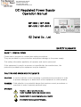
99 Washington Street
Melrose, MA 02176
Fax 781-665-0780
TestEquipmentDepot.com
DC Regulated Power Supply
Operation Manual
GP-305 / GP-503
GP-505 / GP-3010
EZ Digital Co., Ltd.
SAFETY SUMMARY
SAFETY PRECAUTIONS
Please take a moment to review these safety precautions.
They are provided for your protection and prevent damage to the power supply.
This safety information applied to all operator and service personnel.
If the equipment is used in a manner not specified by the manufacturer, the
protection provided by the equipment may be impaired.
CAUTION AND WARNING STATEMENTS
CAUTION : Is used to indicate correct operating or maintenance procedures in order
to prevent damage to or destruction of the equipment or other property.
WARNING : Calls attention to a potential danger that requires correct procedures or
practices in order to prevent personal injury.
SYMBOLS
Caution, risk of electric shocks.
Easily-touched higher temperature parts.
!
Caution(refer to accompanying documents)
PROTECTIVE CONDUCTOR TERMINAL
INSTRUCTIONS
Thank you for purchasing EZ DIGITAL products.
The instruments produced by EZ DIGITAL COMPANY are high products technplogy products
made under strict quality control.
We guarantee their exceptional precision and utmost reliability.
For proper use of this product, please read this manual carefully.
EZ Digital Co., Ltd.
1. To maintain the precision and the reliability of the product , use it in the standard
setting.
Operating temperature
Operating humidity
Storage temperature
:
:
:
5℃ ~ 40℃
80% ~ 50%
0℃ ~ 70℃
2. For quality improvement , the exterior design and specifications of the product
can be changed without notice.
3. Should any further information be required , please contact the EZ DIGITAL
company or sales outlet.
WARRANTY
Warranty service covers one year the date of original purchase.
In case of technical failure a year,repair service will be provided by EZ DIGITAL
company.
We charge for repairs after the one year warranty period expires.
When the failure is a result of user's neglect , natural disaster or accident ,
we charge for repaires regardless of the warranty period.
For more professional repair service , be sure to contact us or sales outlet.
[1 ]
Test Equipment Depot - 800.517.8431 - 99 Washington Street Melrose, MA 02176
FAX 781.665.0780 - TestEquipmentDepot.com
1. INTRODUCTION
GP-305 , 3010 , 503 , 505 series are regulated DC POWER SULLPY units with voltmeter
and amperemeter : GP-305 can supply the DC power of 0 to 30V/5A
GP-503 can supply 0 to 50V/3A.
GP-505 can supply 0 to 50V/5A.
They are provided with continuously variable coarse adjustment and the output voltages,
and with continuously variable current adjustment in a range of 10 to 100%.
Current limiting and overload protection functions are built in to protect the load under
any circumstances.
The supply features anloge voltmeter and amperemeter, enabling the user to monitor
the supply's operation at a glance.
LEDs for Constant current ( C.C ) and Constant Voltage ( C.V ) enables monitoring of
operation status.
Main input voltage AC230V and 50/60Hz are supported.
2. FEATURE
Built in output current limiter circuit
Availability of series and / or parallel operation
[3]
Test Equipment Depot - 800.517.8431 - 99 Washington Street Melrose, MA 02176
FAX 781.665.0780 - TestEquipmentDepot.com
3. PRECAUTIONS
3-1. Line voltage selection
This instrument must be operated with the correct line voltage selector switch setting
and the correct line fuse for the line voltage selected to prevent damage.
The instrument operates from either a 90V to 132V or 198V to 250V line source.
Before line voltage is applied to the instrument , make sure the line voltage selector
switch is set correctly.
In the case of the line voltage selector switch selected , must be operated to the
correct line fuse.
※ This instrument is theⅡ of category
To change the line voltage selection
1. Make sure the instrument is disconnected from the power source.
2. Pull out the line voltage selector switch on the bottom panel.
Select the arrow mark position of the switch from Table 3-1.
Select the arrow mark to the desired position and plug it in.
3. Pull out the line fuse holder containing the fuse for overload protection.
Replace the fuse in the holder with the correct fuse from table3-1 & plug it in.
Table 3-1. Line voltage Selection & Fuse Ratings
Line Voltage
AC
AC
AC
AC
90 ~ 110
108~ 132
198~ 242
207~ 250
Arrow Mark Position
Fuse Ratings (250V)
GP-305/503
GP-505
GP-3010
T5A
T6.3A
T8A
T2.5A
T3.15A
T4A
100V
120V
220V
230V
3-2. INSTALLATION & HANDLING PRECAUTIONS
When placing the power supply in service at your workplace,observe the following
precautions for best instrument performance and longest service life.
1. Avoid placing this instrument in an extremely hot and cold place.
Specifically, don't leave this instrument in a close car,exposed to sunlight in
midsummer, or next to a space heater.
2. Don't use this instrument immediately after bring it in from the cold.
Allow time for it to warm to room temperature. Similary don't move it from a
warm place to a very cold place,as condensation might impair its operation.
3. Do not expose the instrument to wet or dusty enviroments.
[4]
Test Equipment Depot - 800.517.8431 - 99 Washington Street Melrose, MA 02176
FAX 781.665.0780 - TestEquipmentDepot.com
4. Do not place liquid-filled containers on top of this instrument.
A spill could seriously damage the instrument.
5. Do not use this instrument where it is subject to serve viration,or strong blows.
6.Do not place heavery objects on the case,or otherwise block the ventilation hole
7. Do not use this power supply in strong magnetic fields,such as near motors.
8. Do not insert wires , tools , etc. through the ventilation holes.
9. Do not leave a hot soldering iron near the instrument.
10. Do not place this instrument face down on the ground, or damage to the knob
may resuit.
11. Do not connect other power source to + ,- of the output terminal.
12. Ground terminal of power code must connect to the ground.
13. According to output porarity, it solved problem ESD and Floating voltage using
the connect ground port to terminal of output .
14. To connect the ground, be careful at ground porarity of load.
15. Input voltage of instrument must be equal to AC power voltage.
16. It use to thick and short wire of output terminal in possible.
3-3. Cleaning
1. To clean stained casing, lightly rub the stained area with a soft cloth dipped in a
neutral detergent.
2. If the surface of the panel is dirty, use the same method to clean.
If the panel is heavily stained, rub the affected area lighty with a soft cloth soaked
in light neutral detergent or alcohol.
3. Never use highly volatile material such as benzene or paint thinner.
[5]
Test Equipment Depot - 800.517.8431 - 99 Washington Street Melrose, MA 02176
FAX 781.665.0780 - TestEquipmentDepot.com
4. SPECIFICATIONS
Model
GP-305
GP-3010
Output polarity
Output current
Load Regulation
GP-505
Positive & Negative
0 ~5A
0 ~10A
Ripple Voltage
Line Regulation
GP-503
0 ~3A
0 ~5A
Less than 3mVpp
Less than 0.01% +2mV for power source voltage
change of ±10%
Less than 0.01% +3mV for load variation of 0 to 100%
0 ~ 30V (F.S)
0 ~50V (F.S)
Accuarcy of 2.5% for full scale
0 ~ 5A
0 ~10A
0 ~ 3A
0 ~ 5A
Ampermeter Monitor
Accuarcy of 2.5% for full scale
More than 10㏁ at DC 500V chassis and output terminal
Insulation between
More than 50㏁ at DC 500V chassis and AC plug.
Compensation/
Overload protection circuit of constant current
Protection circuit
self restoring type
Voltmeter Monitor
Ambient temperature
5℃ ~ 40℃
Operating Humidity
80% ~ 50%
Dimension
235(W) x 145(H) x 380(D)
Weight
Accessories
Approx.8Kg Approx.12Kg Approx.8Kg Approx.11Kg
Short circuit Bar
Spare Fuse
Power source
Power Consumption
AC 110/230V , 50/60Hz
230VA
450VA
230VA
380VA
Test Equipment Depot - 800.517.8431 - 99 Washington Street Melrose, MA 02176
FAX 781.665.0780 - TestEquipmentDepot.com
5.DECRIPTION OF PANEL FUNCTION
5-1. Front Panel Description
DC POWER SUPPLY GP-505
1
2
3
4
5
10
0
8
A
POWER
6
40
50
10
C.V
9
VOLTAGE
CURRENT
LIMIT
ON
30
V
C.C
7
20
0
COARSE
- GND +
FINE
2
OFF
1
3
11
13
12
5
4
1. POWER SWITCH : This switch turns on and off the power.
2. C.V LED
: Display LED for static state current & voltage operating.
3. CURRENT VR
: The current limiting knob for setting and adjusting the output current in a
range of max. 10 ~100%
4. FINE VR
: The fine adjustment knob of the output voltage.
5. COARSE VR
: The coarse adjustment knob of the output voltage.
6. C.C LED
: Display LED for overcurrent.
7. ZERO ADJUST : The mechanical zero adjuster screw for amperemeter.
If the meter needle is off the zero position when the power is off or with no load,
then adjust the screw by a screw driver while the power is off.
8.CURRENT METER : Indicates the load current
9. ZERO ADJUST
: The mechanical zero adjuster screw for voltmeter.
If the meter needle is off the zero position adjust the screw while the power is off.
10. VOLTAGE METER : Set an output voltage while reading the voltage indication.
11. OUTPUT TERMINAL (-) : The negative side of output terminal.
12. OUTPUT TERMINAL (+) : The positive side of output terminal.
13. OUTPUT TERMINAL (GND) : When the positive polarity or negative polarity is to be connected to
the ground,either an appropriate output terminal should be connected
to the GND by a short circuit bar supplied as accessory.
When no bar connection is made,the terminal is used as the ground terminal
[7]
Test Equipment Depot - 800.517.8431 - 99 Washington Street Melrose, MA 02176
FAX 781.665.0780 - TestEquipmentDepot.com
5-2. Rear Panel Description
4
3
1
2
1. DC FAN
2. SERIAL NUMBER
3. AC INLET
4. VENTILATION
[8]
Test Equipment Depot - 800.517.8431 - 99 Washington Street Melrose, MA 02176
FAX 781.665.0780 - TestEquipmentDepot.com