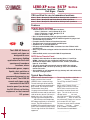
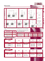
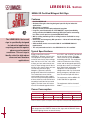
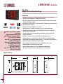
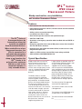
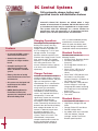
1
Industrial
Catalogue
www.lumacell.com
CATALOG
Special Collection
3. Products Table of Contents ............................................ 11
4. Exit Signs ........................................................................ 15
5. Remotes.......................................................................... 37
6. Battery Units .................................................................. 51
7. DC Systems, Options & Acessories .............................. 59
INDEX
2. IP Rating ........................................................................ 10
Special Collection
1. Hazardous Locations - C.E.C. Classifications ................ 06
Hazardous Locations — C.E.C. Classifications
C.E.C. Code Changes
Classes
In 1998, the Canadian Electrical
Code® (C.E.C.) adopted the
International Electrotechnical
Commission's (IEC) “Three Zone
Area” Classification System for
Class I hazardous locations. The
Zone System is an alternate
classification for Class I
hazardous locations and was
adopted to promote
harmonization with international
standards.
The Canadian Electrical Code
(C.E.C.), Part I, Section 18 Hazardous Locations, identifies three
classes of hazardous locations:
• Class I - Gas and Vapour
Environments
• Class II - Dust Environments
• Class III - Fibers and Flyings
Environments
The Division System for Class I
hazardous locations continues to
be used for existing facilities and
is expected to remain in use at
least for the next few editions of
the C.E.C. For this reason, this
catalogue's certification
information for Class I hazardous
locations includes both the pre1998 Division System and the
new I.E.C. Zone System.
The following pages provide an
overview of C.E.C. hazardous
location classifications.
The 1998 revisions to the C.E.C.
affect only Class I - Gas and
Vapour Environments.
Hazardous location is defined by the
C.E.C. as premises, buildings or parts
thereof in which there exists the
hazard of fire or explosion due to
highly flammable gases and/or
flammable, volatile liquid mixtures that
are manufactured, used or stored in
other than the original containers.
This definition can also be extended
to include combustible dust and
easily ignitable fibers that are likely
to be present in sufficient quantities
to produce an explosive mixture.
Class I — Gas and Vapour Environments
Locations which are deemed
hazardous due to the presence of
gases or vapours that are present
in the air in a sufficient quantity to
produce explosive or ignitable
mixtures.
Locations identified as Class I
require that enclosures and
connectors be explosion-proof.
Class I hazardous locations are
further subdivided into :
• Divisions (pre-1998 version of the
C.E.C.), or
• Zones (I.E.C. Classification - 1998
C.E.C.)
The Division System may still be
used for the maintenance and repair
of existing facilities. All new
construction must use the I.E.C.
Zone Classification.
Divisions
• Division 1 — a Class I location
where the hazardous atmosphere
is expected to be present during
normal operations on a
continuous, intermittent or
periodic basis.
• Division 2 — a Class I location in
which volatile flammable liquids or
gases are handled, processed or
used but in which they would
normally be confined within closed
containers or closed systems from
which they can escape only in the
event of an accidental rupture or
breakdown of the containers or
systems.
6
Hazardous Locations — C.E.C. Classifications
Class I — (continued)
• Zone 0 — Class I locations in
which explosive gas atmospheres
are present continuously or are
present for long periods.
• Zone 1 — Class I locations in
which:
i. explosive gas atmospheres are
likely to occur in normal
operation; or
ii. explosive gas atmospheres may
exist frequently because of
repair or maintenance
operations or because of
leakage; or
iii. the location is adjacent to a
Class I, Zone 0 location, from
which explosive gas
atmospheres could be
communicated.
• Zone 2 — Class I locations in
which:
iv. explosive gas atmospheres are
not likely to occur in normal
operation and if they do occur
they will exist for a short time
only; or
v. flammable volatile liquids,
flammable gases or vapours are
handled, processed, or used,
but in which liquids, gases or
vapours are normally confined
within closed containers or
closed systems from which they
can escape only as a result of
accidental rupture or
breakdown of the containers or
systems or the abnormal
operation of the equipment by
which the liquids or gases are
handled, processed or used; or
vi. explosive gas atmospheres are
normally prevented by adequate
ventilation by which may occur
as a result of failure or abnormal
ope-ration of the ventilation
system; or
vii. the location is adjacent to a Class
I, Zone 1 location from which
explosive gas atmospheres could
be communicated, unless such
communication is prevented by
adequate positive-pressure
ventilation from a source of clean
air, and effective safeguards
against ventilation failure are
provided.
Hazardous Locations
Zones
Area Classification — Divisions vs. Zones
Intermittent Hazard
Zone 1
Division 1
Class I Equipment
Electrical equipment that is
approved for use in Class I
Hazardous Location Areas (HLAs) is
referred to as explosion-proof or
flame-proof. This designation means
that the equipment has been
designed and manufactured to
ensure that it will not become a
source of ignition when used in a
Class I, Gas and Vapour HLA.
All explosion proof equipment is
clearly identified by either:
Division 2
• a «Class I Location» marking
(Division System); or
• a «Type of protection “d”» marking
(IEC Zone System).
Gas Group Designations
Two systems of groupings for gases
are included in the 1998 C.E.C: the
pre-1998 Division Gas Groups
consisting of Groups A, B, C and D;
and the IEC System consisting of
Groups IIA, IIB and IIC.
Both systems are accepted by the
C.E.C.
7
Continuous Hazard
Zone 0
Hazard Under
Abnormal Conditions
Zone 2
Hazardous Locations — C.E.C. Classifications
Class I — (continued)
Comparison of Hazardous Location Gas Group Designations
From Most Restrictive to Least Restrictive
Typical Gas
Hazard
Division Gas
Groups
1998 CEC and IEC
Gas Groups
Acetylene
Hydrogen
Ethylene
Propane
A
B
C
D
IIC
Division Gas Groups
IIB
IIA
I.E.C. Zone Gas Groups
• Group A
acetylene
• Group B
butadiene, ethylene oxide,
hydrogen, manufactured gases
containing more than 30%
hydrogen (by volume),
propylene oxide.
• Group C
acetaldehyde, cyclopropane,
diethyl, ether, thylene,
unsymmetrical dimethyl
hydrazine (UDMH 1, 1-dimethyl
hydrazine).
• Group D
acetone, acrylonitrile, alcohol,
ammonia, benzene, benzine,
benzol, butane, 1-butanol,
2-butanol, butyl acetate,
isobutyl acetate, ethane,
ethanol, ethyl acetate, ethylene
dichloride, gasoline, heptanes,
hexanes, isoprene, methane,
methanol, 3-methyl-1-butanol,
methyl ethyl ketone, 2-methyl1-propanol,
2-methyl-2-propanol, naphtha,
natural gas, petroleum naphtha,
octanes, pentanes, 1-pentanol,
propane, 1-propanol, 2propanol, propylene, styrene,
toluene, vinyl acetate, vinyl
chloride, xylenes
• Group IIC
acetylene, butadiene, propylene
oxide, carbon disulphide,
hydrogen or other gases or
vapour of equivalent hazard
• Group IIB
cyclopropane, diethyl ether,
ethylene, ethylene oxide,
hydrogen sulfide,
unsymmetrical dimethyl
hydrazine (UDMH) or other
gases or vapour of equivalent
hazard
• Group IIA
acetaldehyde, acetone,
acrylonitrile, alcohol, ammonia,
benzine, benzol, butane,
ethylene dichloride, gasoline,
hexane, isoprene, lacquer
solvent vapours, naptha, natural
gas, propane, propylene,
styrene, vinyl acetate, vinyl
chloride, xylenes or other gases
or vapour of equivalent hazard
8
Hazardous Locations — C.E.C. Classifications
Comparison of Division and I.E.C. Zone Systems
Class 1
Gases
and
Vapours
Division
System
I.E.C.
Zone System
Zone 0
Zone 0 locations are a small percentage of all
hazardous locations.
Zone 1
While the wiring practices and acceptable products
differ, Class I, Division 1 locations encompass both
Zones 0 and 1.
Zone 2
Zone 2 and Division 2 are essentially the same.
Division 1
Division 2
Notes
Class II — Dust Environments
Locations which are deemed hazardous
due to the presence of combustible or
electrical conducting dusts.
Class II locations normally require
that enclosures and connectors be
dust tight.
Class II — Divisions
Class II locations are further divided in two divisions as follows:
• Division 1 — In which
combustible dust is or may be in
suspension in air continuously,
intermittently or periodically under
normal operating conditions.
• Division 2 — In which combustible
dust may be in suspension in the air
as a result of infrequent
malfunctioning.
Class II — Group Designations
The Canadian Electrical Code
(C.E.C.), Part 1 Section 18 Hazardous Locations defines
various groups which have been
established for the purpose of
testing and approval.
similarly hazardous
characteristics.
• Group F — Comprising
atmospheres containing carbon
black, coal or coke dust.
• Group E — Comprising
atmospheres containing metal
dust including aluminum,
magnesium, and their commercial
alloys, and other metals of
• Group G — Comprising
atmospheres containing flour,
starch or grain dust, and other
dusts of similarly hazardous
characteristics.
Class III — Fibers and Flyings Environments
Locations which are deemed
hazardous due to the presence of
easily ignitable fibers or
flyings, but in which such fibers
or flyings are not likely to be in
suspension in the air in sufficient
quantities to produce ignitable
mixtures.
Class III locations normally require
that enclosures and connectors be
constructed to minimize the entry of
fibers or flyings.
Class III — Divisions
9
Class III locations are further divided in two divisions as follows:
• Division 1 —In which readily
• Division 2 — In which readily
ignitable fibres or materials
ignitable fibres other than those in
producing combustible flying are
process of manufacture are stored
handled, manufactured or used.
or handled.
IP Rating
lthough IP is mainly a European
rating system, it is referred to
more and more in North America,
especially for lighting fixtures
needing a wet location label.
A
The first number of an IP rating
represents the degree of protection
against penetration of solids and the
second number, the degree of
protection against penetration of
water. So, for example, a wall
sconce that is rated IP65 is
completely protected against
penetration of dust particles and
against jets of water.
Degree of protection
FIRST IDENTIFICATION
NUMBER
Degree of protection against
penetration of solids.
SECOND IDENTIFICATION
NUMBER
Degree of protection against
penetration of water.
0
Not Protected
0
Not Protected
1
Protected against
penetration of solids larger
than 2”
1
Protected against vertical
fall of water drops
2
2
Protected against
penetration of solids larger
than 1/2”
Protected against the fall of
water at a maximum angle
of 15”
3
Protected against rain
3
Protected against
penetration of solids larger
than 3/32”
4
Protected against splashes
5
Protected against
penetration of solids larger
than 1/32”
Protected against jets of
water
6
Protected against waves
7
Protected against the
effects of immersion
8
Protected against the
effects of prolonged
immersion
4
5
Protected against
penetration of dust
6
Completely protected
against penetration of dust
10
CATALOG
Products
Products
RG12S-E Series
page 16
High Capacity Combo Unit
The RG12S-E series combines an efficient exit sign with a high capacity battery unit. This
simplifies typical installations and helps save on wires runs. Energize either many remote
fixtures off of one “combo” or, a few high power fixtures mounted directly on the unit.
LER-HZ Series
page 18
Hazardous Location Exit Sign Class I Zone 2
Extremely resistant to water, strong impacts, vibrations and variations in temperature,
the LER-HSZ is ideally suited for areas whith the risk of presence of flammable gases,
vapors or liquids able to create an explosive gas atmosfere.
LERE-XP Series
page 20
Hazardous Location Exit Sign Class I, II, III
The LERE-XP Series of remote exit signs are designed to cover emergency lighting
applications for the entire spectrum of hazardous locations, where inflammable gases,
vapors, liquids, dust particles or fabrics tissues are permanently present or are likely to exist.
LEREOB12L Series
page 22
NEMA-3R Certified Bilingual Exit Sign
The LEREOB12L Series exit sign is specifically designed for industrial applications
requiring protection against adverse environmental conditions. This exit sign is ideally
suited for high abuse areas, wet locations, dust- and oil-tight applications.
LTEU Series
page 24
Power-Free Exit Sign
The LTEU Series exit sign is completely self-luminous, requiring no electrical source, and
is ideally suited for applications where electrical installation is hazardous or prohibitively
expensive such as historical buildings, mines and industrial facilities.
3LER3000 Series
page 26
NEMA-4X Certified Combo Unit
A complete emergency lighting solution, these products are designed for use in a wide
range of commercial and industrial environments where humidity, dust, water infiltration
and the risk of vandalism are specification criteria.
LER3000 Series
page 28
NEMA-4X Certified Exit Sign
A complete emergency lighting solution, these products are designed for use in a wide
range of commercial and industrial environments where humidity, dust, water infiltration
and the risk of vandalism are specification criteria.
RG-X Series
page 30
Hazardous Locations Unit and Combo, Class I, II, III
Extremely resistant to water, strong impacts, vibrations and variations in temperature,
the LER-HSZ is ideally suited for areas whith the risk of presence of flammable gases,
vapors or liquids able to create an explosive gas atmosfere.
3LERHZ Series
page 32
Combination Unit for Class I Zone 2 Hazardous Locations
The 3LERHZ Series of combination units (unit equipment and exit sign) are designed
specifically for installation in hazardous locations and other high-abuse, industrial
environment.
12
Products
page 36
MQM-HZ Series
Remote Fixture for Hazardous Locations Class I Zone 2
The MQM-HZ Series of remote fixtures has been designed specifically for
installation in hazardous locations and other and high-abuse, industrial
environments.
page 38
MQM-NX Series
Remote Fixture - Water Proof NEMA-4X Series
A complete emergency lighting solution, these products are designed for use in a wide
range of commercial and industrial environments where humidity, dust, water infiltration
and the risk of vandalism are specification criteria.
page 40
Saf-T-Ray Series
Vandal Resistant Wall Mount Remote Head
The Saf-T-RayTM wall sconce unit was designed and engineered with durability and
sophistication in mind. Its low-profile aesthetic design will provide an attractive
alternative to the typical two-headed standard emergency lighting unit.
page 42
RS10XP Series
Remote Lighting Fixtures for Hazardous Location Class I, II, III
The RS10XP Series of remote emergency lighting heads is designed to cover emergency lighting
applications for the entire spectrum of hazardous locations, where inflammable gases, vapors,
liquids, dust particles or fabrics, tissues are permanently present or are likely to exist.
page 44
RS-WP Series
Remote Fixture - Water Proof Series
PAR 36, surface-mounted industrial remote fixtures. Available in single, double or triple
head fixtures. Durable thermoplastic construction suitable for industrial or high abuse
areas.
page 45
RS-WPRB Series
Water Proof Series
Sealed beam, PAR 36, surface-mounted, rubber coated industrial remote fixture.
page 45
MT-W4T Series
Water Proof Series
NEMA-4X listed, surface-mounted, square industrial remote fixture. Available with
tungsten or quartz lamps in single or double head configurations. Gray fiberglass base
and clear polycarbonate lens.
page 46
RS10/RS20/RS30T Series
Surface Mounted Series
PAR36, surface-mounted, large remote fixtures. Single, double or triple head. Positive
aim swivel. Available in factory white (standard) and black.
page 47
RSQB/RSQBD/RSQB2 Series
Surface Mounted Series
13
Cubic, vandal-resistant surface-mounted fixture. Single, double or twin cube with center
body. Available in factory white (standard) and black with frosted polycarbonate cube.
Products
RGS-DT Series
page 50
NEMA-12 Cassified, 6, 12 and 24 Volts Battery Units
The RGS-DT Series battery units are specifically designed for use in industrial facilities
where equipment is exposed to dust, water, oil or corrosive substances.
RG-NX Series
page 52
NEMA-4X Certified Battery Unit
A complete emergency lighting solution, these products are designed for use in a wide
range of commercial and industrial environments where humidity, dust, water infiltration
and the risk of vandalism are specification criteria.
RG-HZ Series
page 54
Battery Unit for Hazardous Locations Class I Zone 2
The RG-HZ Series of battery units are designed specifically for installation in hazardous
locations and other high-abuse, industrial environments. Extremely resistant to water,
high impacts, vibrations and variations in temperature.
IPLTM Series
page 56
IP65 Linear Fluorescent Fixture
The IPLTM Series of fluorescent fixtures by Lumacell are offered as normally on standard
linear fluorescent fixtures. When used with one of our fluorescent inverters, the IPLTM is
converted to a self-powered emergency lighting unit.
LUMA Source Series
page 62
120 VDC Central Single Source
In an existing or new installation where exit signs and emergency lighting
may be supplied by a single 120VDC source using a common negative
wire and a switched positive.
DC Central Systems
page 64
Fully Automatic Charger
Lumacell’s Central DC Systems are utilized where a large number of remote heads or
standard 120 Volt incandescent fixtures. The systems offer the advantage of a central
location for maintenance with full supervision of all operating functions.
Zone Sensing VSR Series
page 68
The VSR (Voltage Sensing Relay) option activates all of the emergency
lighting if only one, multiple or all zones become de-energized through
either a power failure or lighting circuit breaker tripping.
Nexus System
page 70
The NEXUS project started in Australia. Following many successful installations “down
under”,Thomas & Betts decided to adapt NEXUS to North American norms and
specifications, as this system is a truly useful maintenance tool for property owners and
managers.
14
CATALOG
Exit Signs
RG12S-E
Series
High Capacity Combo Unit
Up to 360 watts of Remote Capacity
Features
• High quality steel enclosure with corrosion resistant undercoating
• Fully C860 approved “Exit” legend illuminated with ALINGAP LEDs
• Available in 12 volts, 110, 144, 250 and 360 watts
• Standard 120/347Vac input
• Optional Auto-test charger (available with 110 watts only)
• Long life, maintenance free lead acid battery
• Sealed dust-proof transfer relay
• Solid state pulse type charger standard
Typical Specification
The RG12S-E series
combines an efficient exit
sign with a high capacity
battery unit. This simplifies
typical installations and
helps save on wires runs.
Energize either many
remote fixtures off of one
“combo” or, a few high
power fixtures mounted
directly on the unit
Supply and install a unit that
combines an illuminated LED exit
sign with an emergency light battery
unit. The housing and faceplate shall
be constructed of steel. The
faceplate shall come standard with
knock out chevrons. The light source
for the exit sign shall be LED. The
LED lamps shall provide illumination
in normal and emergency operation.
Red LEDs shall be of ALINGAP*
technology. The charger board, the
battery and the LEDs shall be
contained in a single housing. A
diffuser optimized for LEDs shall be
mounted behind the legend to
provide the 6” high by 3/4” stroke
letters with even illumination.
The unit shall include a test switch
and high charge pilot light. The
equipment shall be designed to
furnish exit illumination from the
normal AC source. When a power
failure occurs, the exit sign along
with the emergency heads shall
illuminate for a minimum of 30
minutes. The power available for
emergency lights shall be at least
110 watts or as otherwise specified.
The heads shall require no tools to
aim and shall be as specified. The
exit sign shall be CSA-C860-07
approved.
The equipment shall be Lumacell
Model – RG12S_________________.
Dimensions
10 1/4”
[26.0cm]
16 1/8”
[41.0cm]
16 1/8”
[41.0cm]
13 7/8”
[35.3cm]
5 1/2”
[13.8cm]
13 7/8”
[35.4cm]
10 1/4”
[26.1cm]
5 1/2”
[13.8cm]
16 1/8”
[41.1cm]
B CABINET
(110W and 144W)
23 1/8”
[58.8cm]
5 1/2”
[13.8cm]
C CABINET
(250W and 360W)
5 3/8”
[13.8cm]
16
EXAMPLE:
RG12S110
Series
RG12S110 =
12V-110watts
E
2
Lettering # of Heads
E=
EXIT
MT9W
B
ZC
AT
Head Style and Wattage
Colour*
Voltage
Options
MT9W =
mini tungsten, 12V - 9watt, wedge base
RG12S144 =
12V-144watts
1=
one head
MT18W =
mini tungsten, 12V - 18watt, wedge base
RG12S250 =
12V-250watts
2=
two heads
MQ8W =
mini halogen, 12V - 8watt, quartz bi-pin
RG12S360 =
12V-360watts
3=
three heads
MQ12W =
mini halogen,12V -12watt, quartz bi-pin
Blank =
Blank =
AT =
factory white 120/347VAC autotest (110w only)
B=
Black
ZC =
277VAC
Blank =
No options
Series
Blank =
no heads
RG12S-E
Ordering Information
MM12W =
mini halogen,12V - 12watt, MR16
MM20W =
mini halogen, 12V - 20watt, MR16
LH9W =
large tungsten ,12V - 9watt, wedge base
LH18W =
large tungsten, 12V - 18watt, wedge base
LH25W =
large tungsten,12V - 25watt, DCB
LQ12W =
large halogen,12V - 12watt, quartz bi-pin
LQ20W =
large halogen, 12V - 20watt, quartz bi-pin
LQ55W =
large halogen,12V - 55watt, quartz bi-pin
SB12W =
large tungsten,12V - 9watt, sealed beam
SB18W =
large tungsten,12V - 18watt, sealed beam
SB25W =
large tungsten, 12V - 25watt, sealed beam
SQ8W =
large halogen,12V - 8watt, quartz sealed beam
SQ12W =
large halogen,12V - 12watt, quartz sealed beam
D12W =
Deco head DR130, 12V - 12watt, MR16
B Cabinet for
110w or
144w and C
Cabinet for
250w or
360w
D20W =
Deco head DR130, 12V - 20watt, MR16
D35W =
Deco head DR130, 12V - 35watt, MR16
D50W =
Deco head DR130, 12V - 50watt, MR16
* Other colours
availble on
demand.
Consult your
sales
representative.
17
*ALINGAP (AlInGaP): Aluminum, Indium, Gallium and Phosphorus. ALINGAP LED
offers a higher light efficacy, with the Lumen/Watt ratio 300% to 500% higher than
the traditional GaAs LED.
AlInGaP Exit signs are designed for 10 years+ of CSA/UL photometric compliance.
AlInGaP LEDs show an annual light loss rate 10 times lowers than the average light
loss of standard GaAs LEDs.
LER-HZ
Series
HAZARDOUS LOCATION LED EXIT SIGN
Class I, Zone 2 - compliant LED exit sign
Features
The LER-HZ Series of Exit
signs has been designed
specifically for installation in
hazardous locations and
other high-abuse, industrial
environments. Extremely
resistant to water, high
impacts, vibrations and
variations in temperature,
the LER-HZ Series is ideally
suited for areas with the risk
of presence of flammable
gases, vapors or liquids
able to create an explosive
gas atmosphere.
• Certified Class I Division2, Groups A, B, C and D as per CSA C22.2
No.137-M1981, Class I, Zone 2, Groups IIC, IIB and IIA
• Temperature Code: T6 (maximum 85ºC as per Canadian Electrical
Code, Part I and CSA C22.2 No.137-M1981)
• Certified CSA C860-07
• Suitable for cold-weather: -20ºC (self-powered model, “CW” option)
and -40ºC (AC-only and AC-DC models)
• Input voltages: 120 to 347Vac universal AC-input; 6 to 48Vdc universal
DC-input
• High impact thermoplastic frame, with built-in gasket to prevent
water infiltration
• Sealed faceplate of heavy-duty, vandal-resistant polycarbonate
• Tamper-resistant, hermetically sealed magnetic test switch
• Self-test / self-diagnostic circuitry is standard on self-powered
models
• Sealed, maintenance-free, Nickel-Cadmium batteries
• Batteries recharge as per CSA requirements and provide 90 minutes
of emergency operation
• Long-life, energy-efficient ALINGAP red LED light source
• Energy efficient – consumes less than 3 watts in AC or DC mode
Typical Specification
Supply and install Lumacell LER-HZ
Series LED exit signs. The equipment
shall operate with universal two-wire
AC input voltage from 120Vac to
347Vac at less than 3 watts and
universal two-wire DC input voltage
from 6Vdc to 48Vdc at less than 2
watts for single and double face
signs. Designed specifically for hostile
environments, the equipment frame
shall be of industrial grade high
impact thermoplastic with a gasket
around lenses and canopy. The
faceplate(s) shall be constructed of
heavy-duty vandal-resistant
polycarbonate and feature an even
illuminated legend. The light source
shall be light emitting diodes (LED).
Red LED technology shall be
ALINGAP. An LED-sensitive diffuser
shall be mounted behind the legend
to provide the 6” high by 3/4” stroke
letters with even illumination.
The equipment shall be certified for
Hazardous Locations: Class I Division
2 Groups A, B, C and D with a
temperature code T6 (Maximum
85ºC). The equipment shall be
designed specifically for high abuse
areas, wet location, and cold weather
(-20°C) applications. The self-powered
model shall stay illuminated during
emergency operation for at least 90
minutes upon AC failure and shall
include a magnetic test switch and
self-testing / self-diagnostic functions.
The equipment shall automatically
self test for 5 minutes every 30 days,
30 minutes every 60 days and 90
minutes annually. A “Service
required” lamp shall be located near
the test switch and flash when a fault
is detected. A two-LED diagnostic
display shall be located inside the
equipment and shall identify the
eventual source of failure (battery,
charger circuitry, or LED lamps).
The exit sign shall be CSA-C860-07
approved.
The exit sign shall be Lumacell
Model – _______________________.
18
LER-HZ
Dimensions
4 3/8”
(11 cm)
2 1/4”
(5.7 cm)
Series
13 1/2”
(34.2 cm)
9 1/8”
(23.2 cm)
13 1/4”
(33.6 cm)
3 1/2”
(8.9 cm)
Power Consumption
Model
AC Specs
AC/DC red
AC/DC green
Self-powered red
Self-powered green
120 to 347Vac
120 to 347Vac
120 to 347Vac
120 to 347Vac
DC Specs
Less than 3W
Less than 3W
Less than 3W
Less than 3W
6 to 48Vdc
6 to 48Vdc
NiCad battery
NiCad battery
Less than 2W
Less than 2W
Min. 90 minutes
Min. 90 minutes
Ordering information
EXAMPLE:
LERHZ
500
SG
SPD
GN
Series
Faces/Mounting
Colour
Voltage
Options
LERHZ =
EXIT
hazardous
location
500 =
single face, ceiling or wall
mount
600 =
double face, ceiling mount only
SG =
grey/grey
Blank =
universal120-347Vac, 6-48Vdc
SPD =
120-347Vac, self-powered c/w diagnostic
(non audible)
VACDC2 =
120Vac, 120Vdc 2 wire (AC only)
NEX =
Nexus System Interface*
Blank =
no option
GN =
green letters
CW =
cold weather*
19
*Nexus option with self-powered models only
*(-20ºC for selfpowered, -40ºC
for AC/DC)
LERE-XP
Series
Hazardous Location
Exit Signs
RSTP
Series
Transfer
Panels
CSA certified for use in hazardous locations
Class I, Zone 1, Groups IIC, IIB and IIA for Severity Code 1 products
Class I, Zone 1, Groups IIB and IIA for Severity Code 2 products
Class I, Zone 2, Groups IIC, IIB and IIA for Severity Code 3 products
Features
REW-XP Series Exit Signs
The LERE-XP Series of
remote exit signs are
designed to cover
emergency lighting
applications for the entire
spectrum of hazardous
locations, where
inflammable gases, vapors,
liquids, dust particles or
fabrics tissues are
permanently present or are
likely to exist. The LERE-XP
remote exit signs can be
connected to the RSTP
transfer panel (see below),
the RG-X Series of battery
equipment, or the Lumacell
DC system.
• CSA Certified for use in hazardous locations:
• Class I, Divisions 1 and 2, Groups A, B, C, D
• Class II, Divisions 1 and 2, Groups E, F, G
• Class III, Divisions 1 and 2
• Die-cast aluminum body with gray epoxy powder coat finish
• Exit housing and faceplate made of industrial-grade 14-gauge steel
and finished in gray enamel
• Faceplate features universal knockout chevrons
• Two-wire input circuit for both AC and DC inputs
• Available in 6, 12, 24 and 120Vac/dc
• LED lamp with ALINGAP LEDs; consumes less than 5 Watts in AC
and DC mode
• New, easy-to-build catalogue number based on the Lumacell Severity
Codes
• CSA certified, meets or exceeds C860-07 requirements
RSTP Series Transfer Panel
• Available with hazardous location housing (Class I, II and III) or
NEMA-1 housing (for use outside the hazardous location area)
• Standard AC input: 120Vac, optional 277Vac, 347Vac; standard DC
input: 6, 12 or 24Vdc
• Two-wire output with permanently present AC/DC low voltage
• Output power: 25W, can drive up to five (5) units of the LERE-XP
remote exit series
• Also available as self-powered exit sign, battery unit and combo unit;
see RG-X catalogue sheet
Typical Specification
LERE-XP Series Remote Exit Sign:
Supply and install the Lumacell
LERE-XP Series remote exit sign.
The exit housing shall be industrial
grade 14-gauge steel and finished in
gray enamel. The faceplate will be
constructed of heavy-duty
14-gauge steel and feature universal
knockout chevrons and the red letters
shall not be less than 6” (150 mm) in
height with a 3/4” (19 mm) stroke.
The sign shall come complete with a
____Volt LED lamp, and function from
one voltage source only, in AC and DC
current. The LED Lamp shall use
ALINGAP LEDs and shall consume less
than 5 watts in either AC or DC current.
The exit sign shall be CSA-C860-07
approved.
The exit sign shall be suitable for
Class ___, Division ___, Group ____.
The exit sign shall be Lumacell
Model - ________________________.
RSTP Series Transfer Panel:
Supply and install the Lumacell
RSTP Series transfer panel for
hazardous location remote exit
signs. The unit shall have two
voltage inputs: ____ Vac and ____
Vdc and shall be able to maintain
an output of ____Volts 25 watts for
the permanent supply of a total of
four remote LED exit signs.
The transfer panel shall be suitable
for Class ___, Division ___,Group ___
or for a NEMA 1 environment.
The unit shall be Lumacell Model __________________.
20
CEILING MOUNT
PENDANT MOUNT
8 3/8”
[21.3cm]
147/8” [37.7cm]
6”
[15.3cm]
33” [83.9cm]
6”
[15.3cm]
173/8” [44.2cm]
123/8” [31.4cm]
9” [22.9cm]
91/4” [23.5cm]
8” [20.3cm]
10”
[25.4cm]
14
107/8” [27.5cm]
S2, S3 and S4
10 / ”
[26.0cm]
281/2” [72.3cm]
6”
[15.3cm]
Severity Class S1,
6”
[15.3cm]
121/4” [31.2cm]
123/8” [31.4cm]
133/8” [34.1cm]
33/8” [8.4cm]
31/2” [9.0cm]
111/4” [28.7cm]
107/8” [27.5cm]
19 / ” [50.50cm]
34
10 / ” [27.5cm]
3 1/8”
[7.8cm]
78
SEVERITY S3, S4
123/8” [31.4cm]
303/4”
[78.0cm]
121/4” [5.7cm]
Before ordering, identify the environment of your application: Class___, Division___,
Group___. Refer to the following chart for the Severity Code to use in your catalogue
number:___________________ .
For temperature information, please
Severity
Environment
look at the table below:
Code
Cl. I, Div. 1, Gr. A, B
Cl. I, Div. 1, Gr. C, D
CI. I, Div. 2, Gr. A, B, C, D
Cl. II, Div. 1 & 2, Gr. E, F, G
Cl. III, Div. 1 & 2
S1
S2
S3
S4
Series
12 3/8”
[31.4cm]
4” [10.1cm]
& RSTP
4 1/8”
[10.4cm]
303/8”
[77.1cm]
8 1 /2”
[21.5cm]
95/8” [24.5cm]
241/4” [61.5cm]
7 1/8”
[18.1cm]
14 / ” [37.7cm]
78
12 3/8”
[31.4cm]
6”
[15.3cm]
5 1 /4 ”
[13.3cm]
No Severity Rating
Series
SEVERITY S1, S2
DOUBLE PENDANT MOUNT
LERE-XP
Dimensions
Certification Guide for LERE-XP Series Exit Signs (40°C ambient)
Severity Code
S1
S2
S3
S4
Temperature Code
T6
T6
T3C
T3C (EGF)
Max 85°C
Max 85°C
Max 160°C
Max 160°C
CSA/UL rating
Ordering Information
EXAMPLE:
LERE1X
-L12
S1
W
Series
Voltage
Lamp Type
Severity Code
Mounting
LERE1X =
exit single face C860 LED
LERE2X =
exit double face C860 LED
-L6 = 6 volts
-L12 = 12 volts
-L24 = 24 volts
-L120 = 120 volts
Blank = L.E.D. less
than 5 watts
S1 = see chart
S2 = see chart
S3 = see chart
S4 = see chart
C = ceiling
P = pendant
W = wall
RSTP
120
12
25
Series
A.C. Voltage
D.C. Voltage
Load Wattage
Housing
RSTP = transfer panel
120 = 120Vac
347 = 347Vac
6 = 6 volts
12 = 12 volts
24 = 24 volts
25 = 25 watts
Blank = NEMA 1
XP = hazardous
location
Transfer Panel
21
EXAMPLE:
LEREOB12L
Series
NEMA-3R Certified Bilingual Exit Sign
Features
The LEREOB12L Series exit
sign is specifically designed
for industrial applications
requiring protection against
adverse environmental
conditions. This exit sign is
ideally suited for high abuse
areas and wet locations
applications.
• Certified NEMA-3R
• Gasketed fiberglass housing designed specifically for industrial
applications
• Gray finish is standard
• Sealed, vandal-resistant polycarbonate faceplate
• Long-life, even illumination of “EXIT SORTIE” legend provided by
energy efficient, ALINGAP technology LED light source consuming
less than 3 watts per face (standard AC/DC model)
• Wall or ceiling mounting; wall or ceiling brackets available for easy
installation
• Normal AC and emergency DC operation – 120 to 347 volts AC input;
6 to 24 DC input
• CSA certified, meets or exceeds C860-01 and NRCAN/C860-01
requirements
• The self-powered version is also CSA C22.2 No. 141 certified
Typical Specifications
Supply and install Lumacell
LEREOB12L Bilingual Led exit sign.
The equipment shall operate with
universal two-wire AC input voltage
from 120 Vac to 347 Vac a less than
3 Watts per face and universal twowire DC input voltage from 6 Vdc to
24 Vdc at less than 3 Watts per face.
The housing shall be of gray
fiberglass, gasketed, specially
designed for industrial environment.
The sealed front cover shall be
constructed of heavy-duty vandalresistant transparent polycarbonate
of 4mm thickness and shall be bent
around the back box for increased
rigidity. The front cover will feature
an even illuminated legend with the
text ”EXIT” and “SORTIE” positioned
one on top of the other. The light
source shall be the new ALINGAP
technology red LED. The equipment
shall be suitable for wall or ceiling
mount and be designed specifically
for high abuse areas, wet locations,
dust and oil-tight applications. The
equipment in a self-powered
configuration shall stay illuminated
during emergency operation for at
least 60 minutes upon AC failure.
The equipment shall be NEMA-3R,
C-860 and NRCan approved.
The equipment shall be Lumacell
Model - _______________________ .
Power Consumption
Model
AC Specs*
AC/DC red
120 to 347 Vac
Self-powered red 120 to 347 Vac
DC Specs*
Less than 3W 6 to 24 Vdc
Less than 3W
Less than 6W NiCad battery
Min. 60 min.
Note: The values of power consumption are for single-face model (max. 6W / bilingual legend).
Note: For the certification guide and temperature codes, please refer to
both pages from the LERE-XP Series of exit signs and the RS10XP Series
of remote lighting fixtures or consult factory.
22
2”
[5.1cm]
po
24 1/8“ [61.4 cm]
po
4”
[10.2 cm]
po
EXAMPLE:
LEREO1W4T
B12L
UNIV
Model
Lettering
Voltage
LEREO1W4T =
single face NEMA-3R, exit/sortie
LEREO2W4T =
double face NEMA-3R, exit/sortie
LSRSO1W4T =
single face NEMA-3R, sortie/exit
LSRSO2W4T =
double face NEMA-3R, sortie/exit
B12L = bilingual
UNIV = 120 to 347
Vac, 6 to 24 Vdc
SP = self-powered
120 to 347 Vac
Series
Ordering Information
23
Double face
Simple face
15“ [38.1 cm]
po
LEREOB12L
Dimensions
LT E U
Series
Power Free Exit Sign
Self-luminous, independent operation exit sign
Features
• Illumination provided by borosilicate glass tubes, internally coated
with zinc sulphide phosphor and filled with tritium gas
• Minimum brightness at time of manufacture is 0.132 foot-lambert
(0.452 cd/m2)
• Decorative, slim-line heavy-duty ABS housing
• Rugged, impact-resistant polycarbonate face
• Spark free construction
• Simple installation – universal direction capability, comes complete
with universal mounting hardware
The LTEU Series exit sign is
completely self-luminous,
requiring no electrical
source, and is ideally suited
for applications where
electrical installation is
hazardous or prohibitively
expensive such as historical
buildings, mines and
industrial facilities. The
LTEU Series can also be
used for all classes and
divisions of explosion-proof
environments such as oil
refineries, pulp and paper
mills, chemical plants and
grain elevators.
• Stands up to extreme temperatures in outdoor or indoor applications
• Standard 12-year life expectancy. 15- or 20-year life expectancies
available as an option
Typical Specification
Supply and install Lumacell LTEU
Series self-luminous exit signs.
The exit shall be constructed of a
thermoplastic housing and be
corrosion proof. The sealed housing
will incorporate no loose or
removable parts allowing for easy
installation. The standard expected
life shall be 12 years with a minimum
guaranteed life of 10 years. The
Wire Guards
460.0079
460.0027
460.0028
Dimensions
Wall Mount
End Mount
Ceiling Mount
standard mounting brackets will allow
for either end/ceiling or wall mount.
Standard signs shall be supplied with
red face, grey frame and white letters
that are 6” high by 3/4” stroke. The
initial average minimum brightness
shall be .132 foot-lambert
(0.452cd/m2)
The Exit shall be Lumacell Model ________________________________.
24
LT E U
EXAMPLE:
1
Series
Faceplates/Mounting
Housing Colour
Life Years
Options
LTEU = exit
LTB3LE/S = exit/sorti
LTB3LS/E = sortie/exit
1 = single face,
universal mount
2 = double face,
universal mount
Blank = grey
WH = white
B = black
Blank = 12 years
15 = 15 years
20 = 20 years
SW = special wording
GN = green background Contact
factory for disposal procedures.
Series
LTEU
25
Ordering Information
3LER3000
Series
Combo Unit
NEMA-4X Certified Combo Unit
Features
Standard
• NEMA-4X Certified for wall or ceiling mount
• High efficiency MR16 halogen lamps up to 12V, 12W or 12V, 5W white
LED, MR16 emergency lights
• Uniform Alingap technology LED illuminated legend
• Comes standard with non-audible advanced diagnostic charger
board, 10 minute time delay and lamp disconnect
• Audible warning and time delay functions can be enabled or disabled
NEMA-4X
• Micro-controller diagnostic system tests, detects and indicates
battery, charger circuitry, LEDs or MR16 lamp failures
Innovative, field-adjustable
lamp head assembly
Choice of MR16 halogen
lamps up to 12V, 12W
or high-efficiency, 5-Watt,
MR16 LED lamps
Long life, energy efficient
ALINGAP technology
red LED illuminated EXIT
legend
Can be wall or ceiling
mounted
Double face available
Suitable for cold weather
applications -40˚C (CW
option — available in 6V only)
• Sealed, maintenance-free nickel cadmium battery
• Non-intrusive magnetic test switch
• Choice of grey, factory white or black housing and face
• NSF Certified for food processing plants
• CSA Certified, meets or exceeds C860-07 requirements
• CSA C22.2 No. 141 Certified
Optional
• Double face
• Cold weather (-40°C; 6Volt Unit)
• No heads (for more remote capacity)
• Fire alarm activated flasher
• Flasher/buzzer (AC power failure)
• Flasher (AC power failure)
Dimensions
3 7/8˝
(9.9cm)
3 1/2˝
(8.7cm)
SINGLE FACE
12 5/8˝
(32.1cm)
9 1/4˝
(23.4cm)
DOUBLE FACE
13 1/4˝
(33.6cm)
26
capacity, the charger will shut-off and
thereafter periodically pulse charge to top
off the battery. This pulse-type charger
promotes long battery life and reduces the
potential for grid corrosion. Its charge
voltage is factory set to ± 1% tolerance
and temperature compensated. The
charger has the functions of Lockout and
Brownout Circuits, and Low Voltage
Disconnection. It protects the unit from
over-current, short-circuit, and reverse
polarity. The unit shall self-test for 1 minute
every 30 days, 10 minutes on the 6th month
and 30 minutes every 12 months. The unit
shall be capable of full recharge in
compliance with CSA specifications. The
unit shall be furnished with a magnetic test
switch. A “Service Required” lamp shall be
located near the test switch and flash when
a fault is detected. A four-LED diagnostic
display shall be located inside the
equipment and shall identify the source of
failure (battery, charger circuitry, or lamps).
The exit sign shall be CSA-C860-07
approved.
The unit shall be Lumacell Model ______________________________________
Series
Supply and install Lumacell 3LER3000
LED exit sign and power pack series. The
equipment shall operate under two
operating voltage, 120Vac or 347Vac. The
equipment frame shall be of industrial
grade polyvinyl chloride with a gasket
around lenses and canopy designed
specifically for hostile environments. The
unit shall be certified for NEMA-4X for wall
or ceiling mount and designed specially for
high abuse areas, wet location, and cold
weather (CW option). The faceplate(s) shall
be constructed of heavy-duty vandalresistant polycarbonate and features an
even illuminated legend. The legend light
source shall be light emitting diodes (LED).
Red LED techno-logy shall be ALINGAP.
Emergency lights shall be fully adjustable
and high efficiency MR16 lamps.
The Lumacell Advanced Diagnostic Microcontroller board shall supply the rated load
for a minimum of a 1/2 hour to 87,5% of
the rated battery voltage. The unit shall be
rated 120/347 V, 60 Hz and be CSA listed.
The unit shall have an output of ___ Volts.
The charger shall at first bulk recharge the
battery, then when the battery is at full
3LER3000
Typical Specification
Power Consumption
AC Specs
Model
3LER3
5LER3
DC Specs
120/347Vac Less than 10W
120/347Vac Less than 10W
6V-36W
12V-60W
Min. 30 minutes
Min. 30 minutes
Wire Guards
With heads
460.0078
460.0060
Without heads
Wall Mount
Ceiling Mount
460.0079
460.0028
Wall Mount
Ceiling Mount
Ordering Information
EXAMPLE:
Series
3LER3 =
6V-36W,
NEMA-4X
5LER3 =
12V-60W,
NEMA-4X
500
2
MI
WH
Faces # of Heads Lamp/Wattage Housing/Face Colour
500 =
single
face
600 =
double
face
Blank =
0 head
2=
two heads
MI =
MR16, 6V-6W
MJ =
MR16, 6V-10W
MK =
MR16, 12V-12W
L=
LED, 12V-5W
WH =
factory white/white
WB =
factory white/black BK =
black/black
BW =
black/white
GW =
grey/white
GB =
grey/black
SG =
grey/grey
CW
Voltage
Options
Blank =
120/347Vac
ZC =
120/277Vac
Blank = no options
*CW = cold weather (-40°C)
FA = flasher (fire alarm activated)
F/B = flasher/buzzer (AC power
failure)
FL = flasher (AC power failure)
GN = green letters
**NEX = Nexus System interface
* Available in 3LER3 only (add
10W of power consumption for
this option). Single face only
** Not available with
(W, FA, F/B, FL)
27
3LER3
LER3000
Series
Exit Sign
NEMA-4X Certified Exit Sign
Features
• Polymeric enclosure is fully gasketed around lens and canopy to
prevent water infiltration - NEMA-4X Certified
• Sealed faceplate of heavy-duty, vandal-resistant polycarbonate with
evenly illuminated legend
• Suitable for cold weather: -40°C for AC/DC models and -25°C for selfpowered (“CW” option)
• Tamper-resistant magnetic test switch
NEMA-4X
• Self-diagnostic circuitry standard on all self-powered models
Sealed heavy-duty, vandalresistant
polycarbonate faceplate
Suitable for cold weather 40˚C (AC/DC model)
and -25˚C on self-powered
model (CW option)
Long-life, energy-efficient
ALINGAP technology
red LED light source
Energy efficient –
consumes less than 3 watts
in AC or DC mode
• Sealed, maintenance-free, nickel cadmium batteries for superior
performance and long life
• Provides 90 minutes of emergency operation (consult factory for
longer operation)
• Long-life, energy-efficient ALINGAP red LED light source
• Energy efficient – consumes less than 3 watts in AC or DC mode
• Normal AC and emergency DC operation – 120 to 347 volts universal
AC 2 wire input; 6 to 48 volts universal DC
• Also available with power pack; see 3LER3000 combo unit
• NSF Certified for food processing plants
• CSA Certified, meets or exceeds C860-07 requirements
• The self-powered version is CSA C22.2 No. 141 Certified
Dimensions
13 1/4˝
(33.6cm)
3 1/2˝
(8.7cm)
3 7/8˝
(9.9cm)
9 1/4˝
(23.4cm)
DOUBLE FACE
SINGLE FACE
28
wet location, and cold weather (-25°C)
applications. The self-powered model shall
stay illuminated during emergency
operation for at least 90 minutes upon AC
failure and shall include a magnetic test
switch and self-testing and self-diagnostic
functions. The equipment shall
automatically self test for 5 minutes every
30 days, 30 minutes every 60 days and 90
minutes annually. A “Service Required”
lamp shall be located near the test switch
and flash when a fault is detected. A twoLED diagnostic display shall be located
inside the equipment and shall identify the
eventual source of failure (battery, charger
circuitry, or LED lamps).
Series
Supply and install Lumacell LER3000
Series LED exit signs. The equipment shall
operate with universal two-wire AC input
voltage from 120Vac to 347Vac at less
than 3 watts and universal two-wire DC
input voltage from 6Vdc to 48Vdc at less
than 2 watts for single and double face
signs. The equipment frame shall be of
industrial grade polyvinyl chloride with a
gasket around lenses and canopy
designed specifically for hostile
environments. The faceplate(s) shall be
constructed of heavy-duty vandal-resistant
polycarbonate and feature an even
illuminated legend. The light source shall
be light emitting diodes (LED). Red LED
technology shall be Alingap. An LEDsensitive diffuser shall be mounted behind
the legend to provide the 6” high by 3/4”
stroke letters with even illumination. The
exit shall be certified for NEMA-4X and
designed specifically for high abuse areas,
LER3000
Typical Specification
The exit sign shall be CSA-C860-07
approved.
The exit sign shall be Lumacell Model _____________________________________.
Power Consumption
AC Specs
Model
120 to 347Vac
AC/DC red
120 to 347Vac
AC/DC green
Self-powered red 120 to 347Vac
Self-powered green 120 to 347Vac
DC Specs
Less than 3W
Less than 3W
Less than 3W
Less than 3W
6 to 48Vdc
6 to 48Vdc
NiCad battery
NiCad battery
Less than 2W
Less than 2W
Min. 90 minutes
Min. 90 minutes
Wire Guards
With heads
460.0079
460.0027
460.0028
Wall Mount
End Mount
Ceiling Mount
Ordering Information
EXAMPLE:
500
WH
Series Faces/Mounting Housing/Faceplate Colour
LER3 =
C860
approved
500 = single face,
universal mount
600 = double face,
universal mount
WH = factory white/white
BK = black/black
BW = black/white
WB = factory white/black
GA = grey/grey
GW = grey/white
GB = grey/black
4X
Voltage
Options
Cabinet
Blank = universal
120-347Vac,
6-48Vdc
SPD = 120-347Vac,
self-powered c/w
diagnostics
(non-audible)
120VACDC2 =
120Vac, 120Vdc 2
wires (AC only)
Blank = no options
GN = green letters
FA = fire alarm activated
flasher
*FB = flasher/buzzer
CW = cold weather
(-25°C for self-powered, 40°C for AC/DC)
**NEX = Nexus System interface
4X = approved
NEMA-4X
* Self-powered models only
** Not available with
(FA, FB, CW)
29
LER3
RG-X
Series
Hazardous Location
Battery Units, Self-Powered Exit Signs, Combination Units
CSA certified for use in hazardous locations
Class I, Zone 1, Groups IIC, IIB and IIA for Severity Code 1 products
Class I, Zone 1, Groups IIB and IIA for Severity Code 2 products
Class I, Zone 2, Groups IIC, IIB and IIA for Severity Code 3 products
Features
The RG-X Series of battery
equipment is designed to
cover emergency lighting
applications for the entire
spectrum of hazardous
locations, where
inflammable gases, vapors,
liquids, dust particles or
fabrics tissues are
permanently present or are
likely to exist.
The RG-X Series combines
in one simple-to-order
catalogue family three
traditional emergency
lighting products with
battery back-up: battery
units with emergency lights,
self-powered exit signs, and
combination units with
emergency lights and exit
sign. The equipment is also
available with additional
emergency power capacity
to drive remote heads and
exit signs.
• CSA Certified for use in hazardous locations:
• Class I, Divisions 1 and 2, Groups A, B, C, D
• Class II, Divisions 1 and 2, Groups E, F, G
• Class III, Divisions 1 and 2
• Die-cast aluminum body with gray epoxy powder coat finish; clear,
impact and heat resistant prismatic glass globe
• Long-life, maintenance-free lead-calcium battery
• Battery charger is current limited, temperature compensated, shortcircuit proof and reverse polarity protected
• Emergency heads with one or twin lamp design
• Self-powered exit (combo) includes a transfer circuit to drive four
remote LED-based exit signs
• Exit sign uses a LED lamp with ALINGAP LEDs
• Exit sign is CSA certified, meets or exceeds C860-07 requirements
• The self-powered version is also CSA C22.2 No. 141 certified
• Easy-to-build catalogue number based on the Lumacell Severity
Codes
• Also available as remote exit signs and remote fixtures; refer to the
LERE-XP and RS10XP catalogue sheets
Typical Specification
30
Supply and install the Lumacell RG-X
Series of hazardous location battery
equipment. The battery unit housing will
be constructed of die cast aluminum
with gray epoxy powder coat finish. The
equipment shall be rated for 120, 277 or
347 volts, 60 Hz input and be CSA listed.
The equipment shall have an output of
____ volts and ___ watts and shall supply
the rated load for a minimum of a 1/2
hour to 87,5% of the rated battery
voltage. The battery shall be a long-life,
maintenance-free lead-calcium type. The
charger shall be fully computer tested
and have its charge voltage set in the
factory to ± 1% tolerance. The charger
shall be current limited, temperature
compensated, short-circuit proof and
reverse polarity protected. The charger
shall be furnished with an electronic
lockout circuit, which will connect the
battery when the AC circuit is activated,
and an electronic brownout circuit, which
will activate the emergency heads when
the utility power dips below 75% of
nominal voltage.
Where required the equipment shall come
complete with ____ heads, each of them
equipped with ___ lamp(s) of ____ watts.
The head housing shall be die-cast
aluminum with gray epoxy powder coat
finish. The lenses shall be a clear, impact
and heat resistant prismatic glass globe.
The head shall be factory sealed, with no
need for external seals.
Where required the equipment shall come
complete with one exit sign and will
include a transfer circuit to maintain the
exit sign permanently lighting in both
normal and emergency operation. The exit
housing shall be industrial grade 14-gauge
steel and finished in gray enamel. The
faceplate will be constructed of heavyduty 14-gauge steel and feature universal
knockout chevrons and the red letters
shall not be less than 6” (150 mm) in
height with a 3/4” (19 mm) stroke. The
sign shall include a LED lamp with
ALINGAP LEDs and shall consume less
than 5 watts in either AC or battery mode.
The equipment shall be suitable for
Class ___ Division ___ Group ____.
The exit sign shall be CSA-C860-07
approved.
The equipment shall be the Lumacell
Model - ________________________.
63/8” [16.3cm]
227/8” [58.1cm]
195/8” [49.9cm]
227/8” [58.0cm]
9 5/8”
[24.4cm]
195/8” [48.9cm]
207/8”
[53.0cm]
143/8” [36.6cm]
273/4” [70.5cm]
6 1 /4 ”
[20.8cm]
211/4” [53.9cm]
233/8” [59.2cm]
201/8” [51.0cm]
18
233/8” [59.2cm]
10”
[25.4cm]
131/8”
[33.4cm]
20 / ” [51.0cm]
LARGE CABINET
181/4”
[46.5cm]
Series
SMALL CABINET
103/8”
[26.4cm]
RG-X
Dimensions
Before ordering, identify the
environment of your application:
Class___, Division___, Group___. Refer
to the following chart for the Severity
Code to use in your catalogue
number:________________________ .
Environment
Severity Code
Cl. I, Div. 1, Gr. A, B
S1
Cl. I, Div. 1, Gr. C, D
S2
CI. I, Div. 2, Gr. A, B, C, D
S3
Cl. II, Div. 1 & 2, Gr. E, F, G
S4
Cl. III, Div. 1 & 2
143/8” [36.6cm]
305/8” [77.8cm]
233/4” [60.4cm]
The temperature code of complete
equipament is given by the type of
emergency head or Exit Sign installed.
For temperature information, please
look at the table below:
Temperature Codes for LERE-XP
Series Exit Signs (40°C ambient)
Severity Code
Temperature
Code
CSA/UL
rating
S1
S2
S3
S4
T3C
T6
T6
T3C
(EGF)
Max Max
Max Max
85°C 85°C 160°C 160°C
Ordering Information
EXAMPLE:
6
36
X
Series
D.C.
Voltage
Capacity/
Cabinet Size
Housing
6=
6 volts
36 = 36 watts [S]*
72 = 72 watts [S]*
108 = 108 watts [L]*
72 = 72 watts [S]*
144 = 144 watts [L]*
200 = 200 watts [L]*
144 = 144 watts [L]*
288 = 288 watts [L]*
RG
12 =
12 volts
24 =
24 volts
* Cabinet size is not
part of the ordering
information. Housing
X=
hazardous
location
Faces
A1
12W
Head
Style
Lamps
Blank =
-0 = no
12W = halogen,
no exit sign
heads
6V, 12V - 12 watts,
RE1 =
A1 = single
quartz bi-pin
single face
remote, 1
20W = halogen,
exit sign
lamp
12V, 24V - 20 watts,
C860,
A2 = single
quartz bi-pin
L.E.D.
remote, 2
RE2 =
lamps
double face A3 = douexit sign
ble remote, Note: for other lamp
C860,
1 lamp
options, please
L.E.D.
contact factory.
S3
TD
Severity
A.C.
Options
Code
Voltage
S1 =
see chart
S2 =
see chart
S3 =
see chart
S4 =
see chart
Blank =
120Vac
ZC =
277Vac
input
ZD =
347Vac
input
Blank =
no options
TD =
time delay
TP =
transfer
panel
31
RG
3LERHZ
Series
Combination Unit for hazardous
locations Location
Features
The 3LERHZ Series of
combination units
(unit equipment and exit
sign) are designed
specifically for installation in
hazardous locations and
other high-abuse, industrial
environment. Extremely
resistant to water, high
impacts, vibrations and
variations in temperature,
the 3LERHZ Series is ideally
suited for areas with the risk
flammable gases, vapors or
liquids that can create an
explosive atmosphere.
Equipped with long-life and
efficient light sources
(ALINGAP LEDs, MR16
halogen lamps) the
equipment offers impressive
illumination performance on
the path of egress.
• Certified Class I Division 2, Groups A, B, C and D as per CSA C22.2
No.137-M19811, Class I, Zone 2, Groups IIC, IIB and IIA
• Certified temperature Codes for several types of emergency lamps
• Certified CSA C22.2 No141
• Certified CSA C860-07
• Polymeric frame, with built-in gasket to prevent water infiltration
• Heavy-duty 1/8-inch thick aluminum back plate with key-holes for
secure wall-mount installation
• Sealed faceplate of heavy-duty, vandal-resistant polycarbonate
• Exit sign module illuminated by long-life, energy-efficient ALINGAP
red LEDs
• Two MR16 halogen lamps, shielded by a cast aluminum housing and
a polycarbonate cover
• Sealed, maintenance-free, Lead-Calcium or Nickel-Cadmium
batteries
• Remote load capacity
• Comes standard with self-test / self-diagnostic functions
• Comes standard with industrial-grade, die-cast Aluminum electrical
box
• ½-inch electrical conduit entry on both sides and at the top
Typical Specification
Supply and install Lumacell 3LERHZ
Series combination of unit equipment
and LED exit sign. Designed specifically
for hostile environments, the equipment
frame shall be of industrial grade
polymeric material with gaskets around
both sides of the frame contour. The
back plate shall be made of 1/8-inch
thick aluminum sheet and shall include
knock-outs for installation on an
electrical box and four keyholes for
alternative installation on a wall surface.
The faceplate shall be constructed of
heavy-duty vandal-resistant
polycarbonate and feature a uniformly
illuminated legend. The light source
shall be light emitting diodes (LED). Red
LED technology shall be ALINGAP. An
LED-sensitive diffuser shall be mounted
behind the legend to provide the 6” high
by 3/4” stroke letters with even
illumination. When specified, the
equipment shall have attached a lower
compartment containing two emergency
lights with adjustable swivels and longlife MR-16 halogen lamps of ___ V and
___ W. The lamps shall be shielded by
cast aluminum housing and protected by
a shock-absorbent, transparent
polycarbonate cover.
The equipment shall be certified for
Hazardous Locations: Class I Division 2
Groups A, B, C and D. The standard AC
input voltage shall be: 120/347Vac. The
equipment shall be equipped with a
magnetic test switch located behind the
face plate and two LED pilot lights: ACon and “Service required”. The unit shall
include self-testing / self-diagnostic
functions monitored by a microcontroller and shall automatically self
test for one minute every 30 days, 10
minutes in the 6th month and 30 minutes
annually. The “Service required” LED
shall light when a fault is detected. A
four-LED diagnostic display located
inside the equipment shall identify the
source of the failure (battery, charger
circuitry, or lamp load). The exit sign
module shall be CSA-C860-07
approved. The combination unit shall be
Lumacell Model –
_______________________.
32
3LERHZ
Dimensions
3 1 /2 ”
[8.9cm]
141/2” [36.8cm]
61/4” [15.6cm]
Series
125/8” [32.1cm]
133/4” [34.9cm]
Power Consumption and Unit Rating
Model
AC Specs
3LERHZ 120/347 Vac 0.15 / 0.06 Amp
3LERHZN 120/347 Vac 0.15 / 0.06 Amp
5LERHZN 120/347 Vac 0.30 / 0.10 Amp
30 min.
36
36
60
Wattage Capacity
1 hr. 1.5 hrs. 2 hrs. 4 hrs.
21
15
12
30
20
15
40
30
20
10
Temperature Codes
Lamp Rating
6V 10W
12V 12W
12V 20W
Temperature Code
T3C
T3A
T2D
Max. Temperature Replacement part #
160 °C
580.0079
180 °C
580.0080
215 °C
580.0068
Note: Use qualified replacement lamps to avoid risk of over-heating
Ordering Information
EXAMPLE:
2
MJ
GG
Series
# of Heads
Lamp/Wattage
Housing/Face
Color
3LERHZ=
6V - 36W, lead acid
3LERHZN =
6V - 36W, NiCad
5LERHZ =
12V - 60W NiCad
Blank =
no heads
2=
2 heads
MJ =
MR16, 6V - 10W
MK =
MR16, 12V - 12W
MW =
MR16 12v- 20 w IR
GG = grey/grey
AT
Voltage
Letters
Color
Blank =
120/347vac
ZC =
120/277vac
Blank =
red letters
G=
green letters
Options
AT =
autotest audible
ATN =
auto Test, nonaudible
NEX =
nexus system
interface
33
3LERHZ
CATALOG
Remotes
MQM-HZ
Series
HAZARDOUS LOCATION Compliant Remote Fixture
Class I, Division 2, Groups A, B, C and D
Class I, Zone 2, Groups IIC, IIB and IIA
Features
The MQM-HZ Series of
remote fixtures has been
designed specifically for
installation in hazardous
locations and other and
high-abuse, industrial
environments. Extremely
resistant to water, high
impacts, vibrations and
variations in temperature,
the MQM-HZ Series is
suited for areas with the risk
of presence of flammable
gases, vapors or liquids
able to create an explosive
gas atmosphere. Besides
their superior endurance,
the fixtures have
outstanding lighting
performance, with a centerto-center egress
illumination up to 70-foot
long and 3-foot wide.
• Certified Class I Division 2, Groups A, B, C and D as per CSA C22.2
No. 9 and No.137-M1981, Class I, Zone 2, Groups IIC, IIB and IIA
• Temperature Codes: T3B (10W and 12W MR16 lamps) and T2C (20W
MR16 lamps), as per Canadian Electrical Code, Part I and CSA C22.2
No.137-M1981)
• Extreme operational temperature range: -40ºC to +40ºC.
• Choice of single- or double-lamp models
• High-efficacy MR16 halogen lamps of 10W, 12W and 20W (see
specification table)
• Input voltage: 6V, 12V, 24V or 120V
• Fully gasketed die-cast aluminum back plate
• Clear polycarbonate cover, UV and impact resistant
• Easy installation on a 4-inch octagonal box (included in the package)
• Comes standard with tamper-proof screws and bit
Typical Specification
shall be listed to CSA C22.2 No. 9
and CSA C22.2 No.137-M1981. The
fixture shall be rated with a
temperature code for the selected
lamps as in the table below.
Each lamp in the fixture shall be able
to be oriented without tools and
should be equipped with high
efficiency MR16 halogen lamp(s) of
___ Volts ___ Watts. The remote
fixtures will provide illumination in
emergency operation and shall
receive their DC power from the
Lumacell battery unit Model________________________ .
The fixture shall be certified for use
The fixture shall be Lumacell Model
in hazardous locations Class I,
Division 2, Groups A, B, C and D and – _______________________.
Supply and install Lumacell MQMHZ Series Model - ________________
remote emergency lighting fixture.
The fixture shall have a single- or
double-lamp configuration (as
specified) and shall include a fully
gasketed die-cast aluminum back
plate and a clear heavy-duty UV
resistant polycarbonate cover. The
fixture shall come standard with a 4inch octagonal box, stainless steel
tamper-proof screws and dedicated
screwdriver bit.
Power Consumption
Lamp type Input Voltage Power (each of 2 lamps)
10 Watts
MR16
6 Volts
12 Watts
MR16
12, 24 Volts
20 Watts
MR16
12, 24, 120 Volts
Temperature code
T3B (Max 165ºC)
T3B (Max 165ºC)
T2C (Max 230ºC)
36
5.7/8”
[14.9cm]
7.1/8”
REMOTE
FIXTURE
[18.1 cm]
2.1/8”
[5.4cm]
4.5/8”
[11.7cm]
Series
4” JUNCTION BOX
3.3/4”
[9.5cm]
JUNCTION
BOX
MQM-HZ
Dimensions
Ordering information
MQM1HZ
12V20WH
SG
Series
Lamp/Wattage
Colour
MQM1HZ =
single lamp
MQM2HZ =
double lamp
6V10W = 6V - 10 Watts, MR16
12V12W = 12V - 12 Watts, MR16
12V20WH = 12V - 20 Watts, MR16-High output
24V12W = 24V - 12 Watts, MR16
24V20W = 24V - 20 Watts, MR16
120V20W = 120V - 20 Watts, GU10
SG = grey
37
EXAMPLE:
MQM-NX
Series
Remote Fixture
NEMA-4X Certified Battery Unit
Features
• Delivers unsurpassed pathway illumination – 70 feet, center-to-center
(with 12V 20W lamp)
• Fully gasketed cast aluminum back plate with clear polycarbonate
cover – NEMA-4X Certified
NEMA-4X
• UV and impact resistant cover
• Choice of three colours: factory white, black or grey
Choice of single or double
head models
• Choice of single or double head models
• Available in 6, 12 and 24 Volt models with various wattages
Fully gasketed cast
aluminum back
plate with clear UV
resistant
polycarbonate cover
Choice of MR16 halogen
lamps up to 24V, 20W or
high-efficiency, 5-Watt,
MR16 LED lamps
• High efficiency MR16 lamps up to 20W
• Easy installation on four-inch octagonal box
• Easy lamp replacement
• Comes standard with tamper-proof screws and bit
• NSF Certified for food processing plants
• CSA Certified to C22.2 No. 9
Typical Specification
Supply and install Lumacell MQM NX
Series Model - _________________ remote
emergency lighting fixtures. These remote
fixtures will consist of either single or double
lamp configurations according to the
design. These fixtures shall be fully
gasketed with a die cast aluminum back
plate and a clear heavy-duty UV resistant
polycarbonate light cover. Units shall be
NEMA-4X certified and specifically designed
for high abuse areas, wet and cold weather
locations. The standard unit will come with
stainless steel tamper-proof screws and bit.
The remote fixture shall be certified to CSA
C22.2 No. 9 and NSF Certified for use in
food processing plants.
The head(s) shall be fully adjustable
without tools and should be equipped with
high efficiency MR16 halogen lamp(s) of
___ volts ___ watts.
The remote fixtures will provide
illumination in emergency operation and
receive their DC power from Lumacell
battery unit Model- ___________________ .
38
7 1/8˝
[18.1cm]
3 3/4˝
[9.5cm]
MQM-NX
Dimensions
Series
4 5/8˝
[11.7cm]
Ordering Information
MQM1NX
6V6W
Series
Lamp/Wattage
Colour
MQM1NX =
single, NEMA-4X
MQM2NX =
double, NEMA-4X
6V6W = 6V-6 watts, MR16
6V10W = 6V-10 watts, MR16
12V12W = 12V-12 watts, MR16
12V20W = 12V-20 watts, MR16
24V20W = 24V-20 watts, MR16
24V12W = 24V-20 watts, MR16
L = 12V-5 watts, LED
Blank = factory
white
BK = black
SG = grey
39
EXAMPLE:
S a f - T- R a y
Series
Wall Mount Remote Head
Robust, vandal resistant,
versatile wall mount fixture
Features
•
•
•
•
•
•
The Saf-T-RayTM wall
sconce unit was designed
and engineered with
durability and
sophistication in mind.
Its low-profile aesthetic
design will provide an
attractive alternative to
the typical two-headed
standard emergency
lighting unit.
The Saf-T-RayTM is
suitable for outdoor and
indoor use, in a wide
range of applications
where aesthetics cannot
be compromised.
Compact wall sconce unit for indoor and outdoor use
High impact resistant polycarbonate diffuser
Die-cast aluminum housing
Available in factory white, black or dark grey finish
Adjustabe lamps
Vandal resistant option
Typical Specification
Wall mount unit shall be gasketed die-cast aluminum housing, impact
resistant polycarbonate diffuser.
To be supplied in factory white, black or dark grey. The lamps shall be in
adjustable for aisle or area distribution.
Fixture shall be supplied with gasket and shall be
suitable for installation on any four inch octogonal box.
Lamp shall be model ____, ____ watts Model Saf-T-Ray by Lumacell.
40
MQM-HZ
Dimensions
Series
Ordering information
SAF
M
12V12W
Series
Lamp Type
Voltage/Wattage
Colour
Options
SAF = exterior
remote
Blank = (1) med. base socket
only (max. 60W), no lamp
included, for non-emergency
M = MR16
Blank = no lamp
6V10W = (2) 6V - 10 watts, MR16
12V12W = (2) 12V - 12 watts, MR16
12V20W = (2) 12V - 20 watts, MR16
24V12W = (2) 24V - 12 watts, MR16
24V20W = (2) 24V - 20 watts, MR16
Blank = factory white
BK = black
DG = dark grey
VR = vandal resistant
screws
41
EXAMPLE:
R S 1 0 X P Series
Hazardous Location Remote Lighting Fixtures
CSA certified for use in hazardous locations
Class I, Zone 1, Groups IIC, IIB and IIA for Severity Code 1 products
Class I, Zone 1, Groups IIB and IIA for Severity Code 2 products
Class I, Zone 2, Groups IIC, IIB and IIA for Severity Code 3 products
Features
• CSA Certified for use in hazardous locations:
• Class I, Divisions 1 and 2, Groups A, B, C, D
• Class II, Divisions 1 and 2, Groups E, F, G
• Class III, Divisions 1 and 2
The RS10XP Series of
remote emergency lighting
heads is designed to cover
emergency lighting
applications for the entire
spectrum of hazardous
locations, where
inflammable gases,
vapors, liquids, dust
particles or fabrics, tissues
are permanently present or
are likely to exist. The
RS10XP remote heads can
be connected to the RG-X
Series of battery
equipment or to the
Lumacell DC system.
• Die-cast aluminum body with gray epoxy powder coat finish
• Clear, impact and heat resistant prismatic glass globe
• Available in 6, 12 and 24V
• Available with single-lamp or twin-lamp combination
• New, easy-to-build catalogue number based on the Lumacell Severity
Codes
Typical Specification
Supply and install the Lumacell
RS10XP Series of hazardous
location remote heads. The head
housing will be die cast aluminum
with gray epoxy powder coat finish.
The lens shall be a clear, impact
and heat resistant prismatic glass
globe. The head shall be factory
sealed. External seals shall not be
required.
The remote head shall come
complete with a ____ mounting
connection and include ____
lamp(s) rated ____ volts ____
watts.
The remote head shall be suitable
for Class ____, Division ____, Group
____.
The remote head shall be Lumacell
Model - ________________________.
42
PENDANT MOUNT
6” [15.3cm]
91/8” [23.0cm]
7” [17.8cm]
7” [17.6cm]
263/4” [67.9cm]
6” [15.3cm]
6” [15.3cm]
93/8” [23.8cm]
95/8” [24.3cm]
35/8” [9.3cm]
177/8” [45.5cm]
3” [7.7cm]
91/8” [23.0cm]
33/8” [8.4cm]
103/4” [27.3cm]
17/8” [4.8cm]
4”
[10.1cm]
7” [17.8cm]
115/8” [29.5cm]
151/4” [38.8cm]
95/8” [24.5cm]
21” [53.3cm]
75/8” [18.1cm]
141/8” [34.9cm]
71/4” [18.4cm]
135/8” [34.6cm]
71/4” [18.4cm]
251/4” [64.0cm]
293/4” [75.6cm]
6” [15.3cm]
WALL MOUNT
5 1/4”
[13.3cm]
71/4” [18.4cm]
SEVERITY S3, S4
CEILING MOUNT
115/8” [29.5cm]
SEVERITY S1, S2, S3
DOUBLE PENDANT MOUNT
R S 1 0 X P Series
Dimensions
251/8” [63.7cm]
Before ordering, identify the
environment of your application:
Class___, Division___, Group___.
Refer to the following chart for the
Severity Code to use in your
catalogue number:
Environment
Severity
Code
Cl. I, Div. 1, Gr. A, B
Cl. I, Div. 1, Gr. C, D
CI. I, Div. 2, Gr. A, B, C, D
Cl. II, Div. 1 & 2, Gr. E, F, G
Cl. III, Div. 1 & 2
S1
S2
S3
S4
Ordering Information
EXAMPLE:
RS10XP
6V
12W
S3
P
Series
Voltage
Lamp Wattage/Type
Severity Code
Mounting
RS10XP = single remote 1 lamp
RS20XP = single remote 2 lamps*
RS20FXP = double remote 1 lamp*
6V = 6 volts
12V = 12 volts
24V = 24 volts
12W =
halogen, 6V, 12V-12 watts, quartz bi-pin
20W =
halogen,12V, 24V- 20 watts, quartz bi-pin
S1 = see chart
S2 = see chart
S3 = see chart
S4 = see chart
C = ceiling mount
P = pendant mount
W = wall mount
Note: For other lamp options,
please contact factory.
*Pendant mount only
For additional information, please look at the table below:
Certification Guide for Remote Lighting Fixtures (40°C ambient)
S1
T4A
Max 120°C
S2
T6
Max 85°C
S3
T1
Max 450°C
S4
T3B (EGF)
Max 165°C
43
Severity Code
Temperature Code
CSA/UL rating
Weatherproof
RS-WP Series
Series
Remote Emergency
Lighting Fixture
RS-WP Series
Dimensions
PAR 36, surface-mounted
industrial remote fixtures
Available in single,
double or triple head fixtures
Durable thermoplastic
construction suitable for
industrial or high abuse areas
Available in black
(standard) and factory white
Tool-less adjustment
and aiming of lamp heads
RS10WP:
4 5/8" (11.8 cm) L x 7 3/8" (18.6 cm) H
x 41/8" (10.5 cm) D
RS20WP:
125/8" (32.1 cm) L x 55/8" (14.3 cm) H
x 4 1/8" (10.5 cm) D
Canopy:
4 1/4" (10.7 cm) Diameter
10
Series # of Heads
RS =
par 36
NEMA 4X listed, surfacemounted, square industrial
remote fixture
Available with
tungsten or quartz lamps in
single or double head
configurations
Gray fiberglass base
and clear polycarbonate lens
H
EXAMPLE:
RS
MT-W4T Series
L
Ordering Information
RS-WPRB Series
Sealed beam, PAR 36,
surface-mounted, rubber
coated industrial remote fixture
For use in high
pressure hose down areas
Available only in black
D
10 =
single head
20 =
double head
30T =
triple head
QWP12V12W
Lamp Wattage/Type
Colour Options
WP6V9W =
Blank =
6V - 9 watts, tungsten, wedge base
black
WP6V__W =
WH =
6V - 18 or 25 watts, tungsten, D.C.B
factory
WP12V__ W =
white
12V - 9 or 18 watts, tungsten, wedge base
WP12V25W =
12V - 25 watts, tungsten, D.C.B.
WP24V__ W =
24V - 9 or 18 watts, tungsten, wedge base
WP24V25W =
24V - 25 watts, tungsten, D.C.B.
QWP6V__ W =
6V - 8, 12, or 20 watts, halogen, quartz bi-pin
QWP12V__ W =
12V - 8, 12, 20 or 55 watts, halogen, quartz bi-pin
QWP24V__ W =
24V - 20 or 70 watts, halogen, quartz bi-pin
SBWP6V__ W = 6V - 9, 12, 18 or 25 watts,
tungsten, sealed beam
SBWP12V__ W = 12V - 12, 18 or 25 watts,
tungsten, sealed beam
QSBWP6V__ W = 6V - 8, 12 or 20 watts,
halogen, quartz sealed beam
QSBWP12V__ W = 12V - 8, 12 or 37 watts
halogen, quatrz sealed beam
WP32V__ W = 32V - 18 or 25 watts,
tungsten, D.C.B.
WP120V__ W = 120V - 10, 15, 30 or 50
watts, tungsten, D.C.B.
*NOTE: "__" = insert wattage required
TC =
teflon
coated
lens
44
Weatherproof
RS-WPRB Series
Dimensions
L
RS10-WPRB:
4 5/8" (11.8 cm) L x 7 3/8" (18.6 cm) H x 41/8" (10.5 cm) D
RS20-WPRB:
125/8" (32.1 cm) L x 55/8" (14.3 cm) H x 4 1/8" (10.5 cm) D
Canopy:
4 1/4" (10.7 cm) Diameter
H
D
Ordering Information
EXAMPLE:
10
SBWPRB6V9W
Series
# of Heads
Lamp Wattage/Type
Options
RS =
par 36
10 =
single head
20 =
double head
30T =
triple head
SBWPRB6V __ W = 6V - 9, 12, 18 or 25 watts,
tungsten, sealed beam
SBWPRB12V __ W = 12V - 12, 18 or 25 watts,
tungsten, sealed beam
QSBWPRB6V __ W = 6V - 8, 12 or 20 watts,
halogen, quartz sealed beam
QSBWPRB12V __ W = 12V - 8, 12 or 37 watts,
halogen, quatrz sealed beam
TC =
teflon
coated lens
Series
RS
*NOTE: "__" = insert wattage required
MT-W4T Series
Dimensions
MT1-W4T:
5.0” (12.8 cm) L x 5.0” (12.8 cm) H x 4.0’’ (10.2 cm) D
MT2-W4T:
7.0” (17.8 cm) L x 5.0” (12.8 cm) H x 4.0’’ (10.2 cm) D
D
L
H
Ordering Information
EXAMPLE:
MQ
1W4T
12V12W
Series
# of Heads
Lamp Wattage/Type
MT =
tungsten
MQ =
halogen
1W4T =
single head
2W4T =
double head
6V9W = 6V - 9 watts, tungsten, wedge base
12V __ W = 12V - 9 or 18 watts, tungsten, wedge base
24V __ W = 24V - 9 or 18 watts, tungsten, wedge base
6V __ W = 6V - 8, 12, or 20 watts, halogen, quartz bi-pin
12V __ W = 12V - 8, 12, or 20 watts, halogen, quartz bi-pin
24V20W = 24V - 20 watts, halogen, quartz bi-pin
45
*NOTE: "__" = insert wattage required
Surface Mounted
RS10/RS20/RS30T
Series
Remote Emergency
Lighting Fixtures
RS10/RS20/RS30T Series
Dimensions
L
RS10: 4.5” (11.4 cm) L x 7.25” (18.4 cm) H x 3.5” (8.9 cm) D
Canopy: 5.0” (12.7 cm) Diameter
RS20: 4.5” (11.4 cm) L x 7.25” (18.4 cm) H x 11.75” (29.9 cm) D
Canopy: 5” (12.7 cm) Diameter
RS30T: 14.0” (35.6 cm) L x 7.25” (18.4 cm) H x 14.0” (35.6 cm) D
Canopy: 9.5” (24.1 cm) Diameter
PAR36, surfacemounted, large remote
fixtures
Single, double or
triple head
Positive aim swivel
Available in factory
white (standard) and black
RSQB/RSQBD/RSQB2
Cubic, vandal-resistant
surface-mounted fixture
Single, double or twin cube
with center body
Available in factory white
(standard) and black with
frosted polycarbonate cube
H
D
Ordering Information
EXAMPLE:
RS
10
Series # of Heads
RS =
par 36
10 =
single head
20 =
double head
30T =
triple head
Q12V12W
Lamp Wattage/Type
Colour Options
6V9W =
Blank =
6V - 9 watts, tungsten, wedge base
factory
6V __W =
white
6V - 18 or 25 watts, tungsten, D.C.B
BK =
12V __ W =
black
12V - 9 or 18 watts, tungsten, wedge base
12V25W =
12V - 25 watts, tungsten, D.C.B.
24V __ W =
24V - 9 or 18 watts, tungsten, wedge base
24V25W =
24V - 25 watts, tungsten, D.C.B.
Q6V __ W =
6V - 8, 12, or 20 watts, halogen, quartz bi-pin
Q12V __ W = 12V - 8, 12, 20 or 55 watts,
halogen, quartz bi-pin
Q24V __ W = 24V - 20 or 70 watts, halogen,
quartz bi-pin
SB6V __ W = 6V - 9, 12, 18 or 25 watts,
tungsten, sealed beam
SB12V __ W = 12V - 12, 18 or 25 watts,
tungsten, sealed beam
QSB6V __ W = 6V - 8, 12 or 20 watts,
halogen, quartz sealed beam
QSB12V __ W = 12V - 8, 12 or 37 watts,
halogen, quatrz sealed beam
32V __ W =
32V - 18 or 25 watts, tungsten, D.C.B.
120V __ W = 120V - 10, 15, 30 or 50
watts,tungsten, D.C.B.
*NOTE: "__" = insert wattage required
TC =
teflon
coated
lens
46
L
D
H
RSQB: 43/4” (12.1 cm) L x 47/8” (12.4 cm) H x 43/4” (12.1 cm) D
RSQBD: 91/2” (24.1 cm) L x 57/8” (15.0 cm) H x 43/4” (12.1 cm) D
RSQB2: 143/4” (37.4 cm) L x 43/4” (11.9 cm) H x 41/2” (11.3 cm) D
Ordering Information
EXAMPLE:
RSQB
6V8W
Special Options
Blank = no options
T = tamper proof
screws
Lamp Wattage/Type
Colour
6V9W = 6V - 9 watts, wedge base
Blank =
12V9W = 12V - 9 watts, wedge base
factory white
12V18W = 12V - 18 watts, wedge base
BK =
24V9W = 24V - 9 watts, wedge base
black
6V8W = 6V - 8 watts, quartz bi-pin
6V12W = 6V - 12 watts, quartz bi-pin
12V8W = 12V - 8 watts, quatrz bi-pin
12V12W = 12V - 12 watts, quatrz bi-pin
24V20W = 24V - 20 watts, quartz bi-pin
M6V6W = 6V - 6 watts, MR16
M6V10W = 6V - 10 watts, MR16
M12V12W = 12V - 12 watts, MR16
M12V20W = 12V - 20 watts, MR16
M12V35W = 12V - 35 watts, MR16
M12V50W = 12V - 50 watts, MR16
M24V20W = 24V - 20 watt, MR16
M24V35W = 24V - 35 watts, MR16
M24V50W = 24V - 50 watts, MR16
Series
Series
RSQB =
single cube
RSQBD =
double cube
RSQB2 =
twin cube
47
Dimensions
Surface Mounted
RSQB/RSQBD/RSQB2 Series
CATALOG
Battery Units
RGS-DT
Series
NEMA-12 Classified, 6, 12 and 24 Volts Battery Units
Harsh environment emergency lighting units-steel,
thermoplastic or fiberglass cabinets
Features
• Solid-state pulse-type charger – current-limited, temperaturecompensated, short-circuit proof and reverse-polarity protected.
• Unit comes standard with electronic lockout and brownout circuits
• Sealed dust-proof transfer relay, test switch and LED indicator lights
• Long-life, maintenance-free sealed lead acid battery
• Wide range of lampheads available – consult Ordering Information
for complete list
• Standard 120/347Vac input voltage with line cord kit
The RGS-DT Series battery
units are specifically
designed for use in
industrial facilities where
equipment is exposed to
dust, water, oil or corrosive
substances. NEMA-12
classified to protect
circuitry from harmful dust
or liquid sprays, sealed and
gasketed unit cabinets are
available in steel,
thermoplastic or fiberglass
in a variety of sizes.
• NEXUS® compatible (for more information on NEXUS®, please
consult the factory)
• CSA C22.2 No. 141 certified
Typical Specification
Supply and install a complete
emergency lighting system as
described herein and shown on
the drawings.
The Lumacell Smart Diagnostic Micro
controller board shall supply the rated
load for a minimum of a 1/2 hour to
87.5% of the rated battery voltage.
The unit shall be rated 120V or 347V,
60 Hz and be CSA listed. The unit
shall have an output of _______ volts.
The charger shall be fully computer
tested and its charge voltage factory
set to ± 1% tolerance. Chargers with
field-adjusted potentiometers are not
acceptable. A pulse-type charger
shall be employed to promote long
battery life and reduce the potential
for grid corrosion. The charger shall
provide a continuous high charge to
recharge the battery, when the
battery is at full capacity, the charger
will shut-off. Periodically the charger
shall provide a pulse of energy to
keep the battery topped off. The
Pulse charge shall be current limited
and precisely regulated by a microprocessing circuit, which samples the
battery in relation to its temperature,
state or charge and input voltage
fluctuations. The charger shall be
current limited, temperature
compensated, short-circuit proof and
reverse polarity protected. The unit
shall be furnished with an electronic
lockout circuit, which will connect the
battery when the AC circuit is
activated, and an electronic
brownout circuit, which will activate
the emergency lights when utility
power dips below 75% of nominal
voltage. A low voltage battery
protection circuit shall be provided
and will disconnect the battery form
the fused output circuit at the end of
discharge. The unit shall self-test for
1 minute every 30 days, 10 minutes
on the 6th month and 30 minutes
every 12 months. The unit shall be
capable of full recharge in
compliance with CSA specifications.
The unit shall be furnished with
sealed dust tight relay, a test switch
and diagnostic LED indicator lights to
continuously monitor the status of
the unit: Battery Failure, Battery
Disconnected, Charger Failure, Lamp
Failure, Service Alarm, AC “ON”,
Charger High Rate.
The unit shall be Lumacell Model ________________________________ .
50
EXAMPLE: RGS 36 DT 2 RB9W AT / RG12S 72 DTF 2 RBQ8W AT /
RG24S 350 DT FG 2 LHQ20W AT
Dimensions
a
b
Thermoplastic
5
Cabinet - size 1 11 /8” [29.5 cm]
d
e
b
13” [32.9 cm]
Dimensions
c
d
5” [12.7 cm]
1
e
f
3
18 /4” [46.4 cm] 13 /4” [35.0 cm]
c
Steel Cabinet size 6
9” [22.7 cm]
121/2” [31.9 cm] 155/8” [39.6 cm] 61/4” [15.9 cm] 201/2” [52.1 cm] 143/4” [17.5 cm] 10” [25.4 cm]
Ordering Information
Series
Fiberglass
5
5
7
Cabinet - size 4 17 /8” [44.7 cm] 19 /8” [49.8 cm] 8 /8” [22.4 cm] 25” [63.5 cm]
Steel Cabinet - 103/ ” [27.4 cm] 137/ ” [34.1 cm] 51/ ” [13.4 cm] 181/ ” [47.1 cm] 125/ ” [32.0 cm]
4
16
4
2
8
size 5
f
a
8” [20.3 cm]
Fiberglass
3
1
1
7
1
1
Cabinet - size 2 11 /8” [29.0 cm] 13 /2” [34.4 cm] 5 /4” [13.2 cm] 18 /8” [47.9 cm] 13 /2” [34.3 cm] 8 /8” [20.5 cm]
Fiberglass
1
1
1
7
Cabinet - size 3 13 /2” [34.3 cm] 15 /2” [39.4 cm] 6 /4” [15.9 cm] 20 /8” [52.9 cm]
RGS-DT
Cabinet
EXAMPLES:
Series
36
72
350
Capacity/
Cabinet Size
RGS =
6 volts
DT
DTF
DTFG
Housing
2
2
2
# of
Heads
36 =
DT =
Blank =
36 watts [ 1, 2, 5 ]*
steel
no
72 =
DTF =
head
72 watts [ 1, 2, 5 ]* thermoplastic
1=
108 =
DTFG =
one
108 watts [ 1, 2, 5 ]*
fiberglass
head
180 =
2=
180 watts [ 1, 2, 5 ]*
two
RG12S =
36 =
heads
12 volts 36 watts [ 1, 2, 5 ]*
72 =
72 watts [ 1, 2, 5 ]*
100 =
100 watts [ 1, 2, 5 ]*
144 =
144 watts [ 1, 2, 5 ]*
200 =
200 watts [ 1, 2, 5 ]*
250 =
250 watts [ 3, 6 ]*
360 =
360 watts [ 3, 6 ]*
RG24S =
144 =
24 volts 144 watts [ 1, 2, 5 ]*
288 =
288 watts [ 1, 2, 5 ]*
350 =
350 watts [ 4 ]*
432 =
432 watts [ 4 ]*
550 =
550 watts [ 4 ]*
720 =
720 watts [ 4 ]*
* Cabinet size is not
part of the ordering
information.
RB9W
RBQ8W
LHQ20W
Head Style/ Lamp Wattage
AT
AT
AT
A.C.
Voltage
LH9W = large tungsten , 6V, 12V, 24V Blank =
9 watts, wedge base
120/347 Vac
LH18W = large tungsten, 12V, 24V input
18 watts, wedge base
ZB =
LH25W = large tungsten, 6V, 12V, 24V 240Vac input
25 watts, DCB
ZC =
LHQ8W = large halogen, 6V, 12V 277Vac input
8 watts, quartz bi-pin
ZE =
LHQ12W = large halogen, 6V, 12V 220Vac, 50hz
12 watts, quartz bi-pin
input
LHQ20W = large halogen, 6V, 12V, 24V 20 watts, quartz bi-pin
LHQ55W = large halogen, 12V 55 watts, quartz bi-pin
LHQ70W = large halogen, 24V 70 watts, quartz bi-pin
SB9W = large tungsten, 6V, 12V 9 watts, sealed beam
SB18W = large tungsten, 6V, 12V 18 watts, sealed beam
SB25W = large tungsten, 6V, 12V, 25 watts, sealed beam
QSB8W = large halogen, 6V, 12V 8 watts, quartz sealed beam
QSB12W = large halogen, 6V, 12V 12 watts, quartz sealed beam
QSB20W = large halogen, 6V 20 watts, quartz sealed beam
RB9W = large rubber tungsten, 6V, 12V 9 watts, sealed beam
RB18W = large rubber tungsten, 6V, 12V 18 watts, sealed beam
RB25W = largerubber tungsten, 6V, 12V, 25 watts, sealed beam
RBQ8W = large rubber halogen, 6V, 12V 8 watts, quartz sealed beam
RBQ12W = large rubber halogen, 6V, 12V 12 watts, quartz sealed beam
RBQ20W = large rubber halogen, 6V 20 watts, quartz sealed beam
Options
A = ammeter
AT =
autotest
CT =
cabtire
DPF6 =
6cct. fuse panel
HTR =
heater & thermostat
LC =
line cord
LD =
lamp disconnect
LTS =
light activated test
switch
*NEX =
NEXUS system
interface (6+12V only)
RRT =
remote test receiver
TC =
teflon coated lens
TD =
time delay
(programmable)
TL =
twist lock plug
TMBB =
AC/DC terminal block
TMBD =
DC terminal block
TMBK =
AC terminal block
V=
voltmeter
* Not all options
available with NEXUS.
Consult factory.
51
RGS
RG12S
RG24S
RG-NX
Series
Battery Unit
NEMA-4X Certified Battery Unit
Features
Standard
NEMA-4X
Fully gasketed cast
aluminum back
plate with clear UV
resistant
polycarbonate
cover
Long-life, maintenancefree sealed lead acid
battery
Choice of MR16 halogen
lamps up to 12V, 20W
or high-efficiency, 5Watt, MR16 LED lamps
Mounting: wall mount
Unit capacity: up to 108W
Suitable for cold weather
applications — -40˚C
(CW option)
• Delivers unsurpassed pathway illumination – 70 feet, center-to-center
(with 12V 20W lamp)
• Fully gasketed cast aluminum back plate with clear polycarbonate
cover – NEMA-4X Certified
• Choice of three colours: factory white, black or silver grey
• Comes standard with non-audible advanced diagnostic charger
board, 10 minute time delay and lamp disconnect
• Audible warning and time delay functions can be enabled or disabled
during installation
• Micro-controller diagnostic system tests, detects and indicates
battery, charger circuitry or MR16 lamp failures
• Non intrusive magnetic test switch
• High efficiency MR16 lamps, up to 20W
• Long-life, maintenance free sealed lead acid battery
• 1/2” rigid conduit entry on top and back
• Can be installed on 4-inch junction boxes
• Comes standard with tamper-proof screws and bit
• Standard 120/347Vac input voltage
• NSF Certified for food processing plants
• CSA C22.2 No. 141 Certified
Optional
• NEXUS® compatible (for more information on NEXUS®, please
consult factory)
• Universal bracket (for mounting on poles, I-beams or Superstrut®
metal framing)
• Cold weather option (-40ºC)
• Bracket pole-beam-wall mounting
Dimensions
17 3/4˝
(45.1cm)
5 3/4˝
(14.6cm)
7˝
(17.7cm)
52
Supply and install the Lumacell NEMA-4X
Certified RG-NX Series battery unit.
The Lumacell Advanced Diagnostic
Micro-controller charger board shall
supply the rated load for a minimum of
30 minutes to 87.5% of the rated battery
voltage. The charger incorporates lockout
and brownout circuits, and low voltage
disconnection. It protects the unit from
over-current, short-circuit, and reverse
polarity. The unit shall be rated 120/347V,
60Hz. The unit shall have an output of
___ volts.
This unit shall self-test for 1 minute every
30 days, 10 minutes on the 6th month
and 30 minutes every 12 months. The unit
shall be furnished with a non-intrusive
magnetic test switch. A “Service
Required” lamp shall be located near the
test switch and flash when a fault is
detected. A four-LED diagnostic display
shall be located inside the equipment and
shall identify the source of failure (battery,
charger, circuitry, or lamps).
Series
Specifically designed for high abuse areas,
wet locations, and cold weather (CW
option -40°C), the housing shall be fully
gasketed with a cast aluminum back plate
and clear heavyduty UV resistant
polycarbonate cover. The heads shall be
fully adjustable without tools and the lamps
shall be high efficiency halogen MR16. The
standard unit shall be equipped with
tamper-proof screws and bits.
RG-NX
Typical Specification
The unit shall be CSA C22.2 No.141.
certified. It shall also be NSF Certified for
use in food processing plants.
The unit shall be Lumacell Model _____________________________________.
Accessories (order as a separate item)
PMK Kit (screws included)
Additional bit for
tamperproof screws
TPB
Universal bracket
(for mounting on poles,
I-beams or Superstrut®
metal framing)
PMK
Beam Mounting
Superstrut Mounting
Ordering Information
EXAMPLE:
36
2
M6W
Series
Capacity
# of Heads
Lamp/Wattage
Colour
RGNX = 6 volts,
NEMA-4X
RG12NX = 12
volts, NEMA-4X
36 = 6V-36W
72 = 12V-72W
108 = 12V-108W
2 = 2 heads
M6W =
mini halogen, 6V-6
watts, MR16
M10W =
mini halogen, 6V-10
watts, MR16
M12W =
mini halogen, 12V-12
watts, MR16
M20W =
mini halogen,12V-20
watts, MR16
L=
12V-5W LED
Blank =
factory white
BK =
black
SG =
grey
A.C./
Voltage
Blank =
120/347Vac
ZC =
277Vac
Options
Blank =
no options
CW1 =
cold weather 120Vac
*CW3 =
cold weather 347Vac
**NEX =
NEXUS system
interface
*Available in 6V only.
**Not all options
available with NEXUS.
Consult factory.
53
RGNX
RG-HZ
Series
Battery Unit for
hazardous locations
Features
• Certified Class I Division 2, Groups A, B, C and D as per CSA C22.2
No.137-M19811, Class I, Zone 2, Groups IIC, IIB and IIA
• Certified temperature Codes for several types of emergency lamps
• Certified CSA C22.2 No141
• Polymeric frame, with built-in gasket to prevent water infiltration
• Heavy-duty 1/8-inch thick aluminum back plate with key-holes for
secure wall-mount installation
• Two MR16 halogen lamps, shielded by a cast Aluminum housing and
a polycarbonate cover
The RG-HZ Series of
battery units are designed
specifically for installation
in hazardous locations and
other high-abuse,
industrial environments.
Extremely resistant to
water, high impacts,
vibrations and variations in
temperature, the RG-HZ
Series is ideally suited for
areas with the risk of
flammable gases, vapors
or liquids that can create
an explosive atmosphere.
Equipped with efficient
MR16 halogen lamps and
with generous remote
power capabilities, the
equipment offers
impressive illumination
performance along an
extensive path of egress.
• Sealed, maintenance-free, Lead-Calcium batteries with up to 120 W
emergency power
• Built-in microcontroller-based battery charger and self-test /
self-diagnostic circuitry
• ½-inch electrical conduit entry on both sides and at the top
Typical Specification
Supply and install Lumacell RG-HZ
Series of battery units. Designed
specifically for hostile environments,
the equipment frame shall be of
industrial grade polymetric material
with gaskets around both sides of the
frame contour. The frame shall be fixed
between two plates made of 1/8-inch
thick aluminum sheet. The back plate
shall include four keyholes for wallmount installation. The front plate shall
include two water-tight lenses for pilot
lights: AC-on and “Service required”.
When specified, the equipment shall
have attached a lower compartment
containing two emergency lights with
adjustable swivels and long-life MR-16
halogen lamps of ___ V and ___ W. The
lamps shall be shielded by cast
aluminum housing and protected by a
shock-absorbent, transparent
polycarbonate cover.
The equipment shall be certified for
Hazardous Locations: Class I Division
2 Groups A, B, C and D, CSA C22.2
N. 141. The standard equipment
shall have a dual AC input voltage:
120/347Vac and shall be equipped
with a magnetic test switch located
on the left side of the frame. The unit
shall include self-testing / selfdiagnostic functions monitored by a
micro-controller and shall
automatically self test for one minute
every 30 days, 10 minutes in the 6th
month and 30 minutes annually. The
“Service required” LED shall light
when a fault is detected. A four-LED
diagnostic display located inside the
equipment shall identify the source of
the failure (battery, charger circuitry,
lamp load). The battery unit shall be
Lumacell Model –
_______________________.
54
RG-NX
Dimensions
3 1 /2 ”
[8.9cm]
141/2” [36.8cm]
61/4” [15.6cm]
Series
125/8” [32.1cm]
133/4” [34.9cm]
Power Consumption and Unit Rating
Model
AC Specs
30 min.
36
72
120
RGHZ36 120/347 Vac 0.17 / 0.06 Amp
RG12HZ72 120/347 Vac 0.30 / 0.10 Amp
RG12HZ120 120/347 Vac 0.30 / 0.10 Amp
Wattage Capacity
1 hr. 1.5 hrs. 2 hrs. 4 hrs.
21
15
12
42
30
24
12
70
50
40
20
Temperature Codes
Lamp Rating
6V 10W
12V 12W
12V 20W
Temperature Code
T3C
T3A
T2D
Max. Temperature Replacement part #
160 °C
580.0079
180 °C
580.0080
215 °C
580.0068
Note: Use qualified replacement lamps to avoid risk of over-heating
Ordering Information
EXAMPLE:
RGHZ
36
2
M10W
ATN
Series
Capacity
# of Heads
Lamp/Wattage
Colour
RGHZ = 6 volts
RG12HZ = 12
volts
36 = 6V-36W
72 = 12V-72W
120 = 12V-120W
Blank = no
heads
2 = 2 heads
M10W =
6V - 10 watt, MR16
M12W =
12V - 12 watt, MR16
M20W =
12V - 20 watt, MR16-IR
Blank =
grey, standard
A.C./
Voltage
Blank =
120/347vac
ZC = 277vac
Options
AT = autotest audible
ATN = auto Test ,nonaudible (standard)
NEX = nexus system
interface
I P L TM
Series
IP65 Linear
Fluorescent Fixture
Sturdy construction, easy installation,
wet location fluorescent fixture
Features
• IP65 rated for wet and damp locations
• Polycarbonate enclosure and lens, vandal resistant and UV stabilized
Rust proof hardware
• Ceiling, surface or pendant mounting
• Low profile, less than 4” deep
• Ultra efficient specular reflector with optimized shape
The IPL Series of
fluorescent fixtures by
Lumacell are offered as
normally on standard
linear fluorescent fixtures.
When used with one of our
fluorescent inverters, the
IPLTM is converted to a
self-powered emergency
lighting unit. Suitable for
damp or wet location, the
IPLTM, thanks to its
polycarbonate enclosure
and lens as well as the
rustproof hardware, is
truly a durable fixture.
TM
• 32W T8 or 54W T5HO
• 90 minutes of emergency operation when installed with our RSFSP or
AM inverters
• Emergency operation from external DC power source when installed
with our RSF Series inverters
• High efficiency and reliable electronic ballast, instant start or 3-step
programmed rapid start
• 120Vac to 277Vac universal and 347Vac input voltage available
• CSA certified to CAN/CSA-E60598-1:02
Typical Specification
Supply and install Lumacell IPLTM
Series of fluorescent fixtures as
specified. The luminaire shall
operate from 120Vac to 277Vac or
347Vac and use high quality instant
start or 3-step programmed rapid
start high efficiency electronic
ballasts.
The body and lens shall be
constructed of UV stabilized
industrial grade vandal resistant
polycarbonate. A durable formed
gasket shall be provided between
the enclosure and the lens and
shall be designed specifically for
hostile environments. The reflector
shall be made of highly specular
material and formed to maximize
light output efficiency. All parts
shall be corrosion resistant. A
metal plate used to retain the
ballast and reflector also serves to
dissipate heat, therefore
lengthening ballast life.
Lamps shall be as specified, either T8
or T5 HO linear fluorescent lamps, 32W
or 54W. The lamps shall not be
supplied with the luminaire. Models
with an inverter from the RSFSP/AM
series and illuminate one or two lamps
during emergency operation for at least
90 minutes upon AC failure. During
power outage, dual voltage source
(AC/DC) models with an inverter from
the RSF series, shall illuminate one
lamp while the DC voltage is present.
The fixture shall be CSA approved
and meet IP65 requirements.
The inverters of RSF series shall be
CSA approved.
The inverters of the RSFSP/AM series
shall be CSA or cUL approved.
The fixture shall be Lumacell Model:
IPL __________________
56
I P L TM
Dimensions
36” [91cm]
Series
6 3/4”
[17cm]
33/4” [10cm]
503/4” [129cm]
Ordering Information
EXAMPLE:
IPL
8
Series
Lamp type*
A.C./
Voltage
IPL =
48" (122cm)
linier
fluorescent
8=
2x lamps 32 watts T8
5=
2x lamps 54 watts
T5HO
Blank =
AC only 120 to
277Vac
3=
A.C. only 347Vac
*Lamps not included
Accessories
Self-powered, one lamp emergency
AM32-L = inverter for IPL8 (complete code = IPL8AM32-L)
RSFSP⁄U⁄1100 = inverter for IPL8-3 (complete code = IPL8-3 RSFSP⁄U⁄1100)
AM12 = inverter for IPL5 (complete code= IPL5AM12)
Self-powered, two lamps emergency
AM7 = inverter for IPL8 (complete code= IPL8AM7)
RSFSP⁄U⁄1100 = inverter for IPL8-3 (complete code= IPL8- 3RSFSP⁄U⁄1100)
Two lamp model not available for T5 bulb (IPL5)
AC⁄DC option, using a remote battery, one lamp only in emergency mode:
RSF3200 = 6 volts, 120Vac
RSF3200ZD = 6 volts, 347Vac
RSF123200 = 12 volts, 120Vac
RSF123200ZD = 12 volts, 347Vac
RSF243200 = 24 volts, 120Vac
RSF243200ZD = 24 volts, 347Vac
RSF323200 = 32 volts, 120Vac
RSF323200ZD = 32 volts, 347Vac
RSF483200 = 48 volts, 120Vac
RSF483200ZD = 48 volts, 347Vac
RSF1203200 = 120 volts, 120Vac
RSF2103200ZD = 120 volts, 347Vac
57
For more information on the RSF Series, please refer to Options & Accessories in
your Lumacell catalogue.
CATALOG
Options & Acessories
LumaSource
Series
Time and labour saver
only one conduit required!
In an existing or new installation where exit signs and
emergency lighting may be supplied by a single 120VDC source
using a common negative wire and a switched positive.
3 wire output from the system reduces the number of
conductors by up to 40%. It also eliminates 50% of the conduit,
EMT or BX runs by using a single common conduit for LED
exits and emergency lighting remotes.
Operations
Features
• Single-source 120 VDC supply
for both exit and emergency
lights
• Reduced number of conductors
• Eliminates 50% of conduit, BX
or EMT runs for exit and
emergency lighting
• Control and supervision
functions on single modular
board
• Complete package of full
supervisory functions and
alarms included in standard unit
• Floor-mount cabinet
• Battery is sealed maintenance
free lead calcium
• All LumaSource Series systems
are designed and manufactured
in Canada
• CSA and Ontario Hydro
approved
• BMEC (Building Materials
Evaluation Commission)
approved for compliance to the
Ontario Building Code
• Overall reduction on power
consumption using LED exit
signs
• 120 VDC Central Single Source
Emergency Lighting System
LumaSource Series Central
Emergency Lighting
Systems are available in freestanding cabinet
style enclosures.
• Heavy duty, sheet-steel cabinet.
• Cabinets are painted ASA No. 61 grey
electrolyte resistant enamel.
• Locking and hinged front door.
• Front access to battery charger for
ease of inspection and servicing.
• Generous ventilation provided
Charger / Controls
Lumacell’s solid state fully automatic
charger features single module
control board design. This feature
provides cost effective superior
performing equipment, with ease of
maintenance and serviceability.
Standard Features and
Controls
60
• LVD at 91% of nominal Battery
voltage
• Temperature Compensation
• Ground Fault Alarm (Audible &
Visual)
• DC Volt & Ammeter (2% Accuracy)
• AC present LED indicator
• Float level Charge LED indicator
• Equalize level Charge LED
indicator
• Charger Failure Alarm
• AC Failure Alarm
• High Battery Voltage Alarm
• Test Switch
• Remote Monitor Alarm Panel
• Brownout Protection
• Dry Contacts
• BMEC - Ontario Building Materials
Evaluation Commission Approved
• SPF - sprinkler-proof cabinet
comes with drip shield
Optional Features Code
• Time Delay TD
• 3 Phase Sensing 3PH
• 12 Hour Recharge 12HR
• 30 or 90 day equalize cycle CYC
30 (90)
Application
New construction or retro-fit, the
LumaSource Series utilizes the latest
technology and engineering to
reduce the cost of emergency
lighting installations. The unique 3
wire design allows for the use of just
one conduit. With one positive dc
normally energized conductor and a
common negative conductor the LED
exits are supplied constant power.
With the same common negative
conductor and a switched positive
dc conductor the remote emergency
lights are powered on demand.
Available in sizes from 4120 watts to
22520 watts for 30 minutes.
Electrical
Input: 120V, 240V, 347V, 600V AC
60HZ Single Phase
Output: 120V DC (3 wire unswitched
positive, common and switched
positive)) Systems have been
designed for minimum 1/2 hour
operation time and are capable of
full recharge in 24 hours.
For systems rating chart and
ordering guide please see Page 63.
Other discharge times are available
upon request.
Canada. Limit room ambient
temperature between 0oC to
35oC (32oF to 95oF).
Optimum system
performance occurs at 25oC
(77oF). A battery service life
is defined as the period
which the battery could still provide
at least 80% of its rated capacity.
Series
The complete system is guaranteed
for a period of one (1) year against
defects in workmanship and
materials. The battery portion of the
equipament carries a ten (10) year
pro-rata warranty during its useful
service life against defects in
workmanship and materials. The
battery warranty is subject to the
provision of normal testing and
inspection as specified in the
Canadian Electrical Code, Section
46-102, and National Fire Code of
LumaSource
Warranty
Approvals
• CSA Certified
• Ontario Hydro: Rule 46-108 (3)
Typical Interconnection Wiring Diagram
CAD Drawing illustrates
how the LumaSource
Series is applied,
saving time, material
and money.
Call your local Lumacell
Representative for
further information, or
application assistance.
Develop a Model Number as shown in the following chart
(1)
System
Designation
(2)
Single
Phase
(3)
Battery
Type
(4)
Capacity
in Watts
(5)
Qty of
Exit Signs
LS4
120Vac
240Vac
347Vac
600Vac
SL
4120
6400
9390
11260
13140
18780
22520
50E
100E
Sealed
Lead
Calcium
(6)
Mounting
(7)
Output
Voltage
C = Console 120V DC
(8)
(9)
Discharge
Optional
Time
Equipment
(Minutes)
30
TD
3PH
12HR
For other
CYC30
discharge
CYC90
times please
contact factory
System
Series
Console
HxWxD
LS4 4120
LS4 6400-11260
LS4 13140-22520
38” x 38” x 18”
38” x 38” x 28”
56” x 38” x 28”
61
Enclosure Dimensions
D C Central Systems
Fully automatic charger, battery and
specified transfer and distribution features
Lumacell’s Central DC Systems are utilized where a large
number of remote heads or standard 120 Volt DC fixtures such
as incandescent lamps may be supplied from a single source.
The systems offer the advantage of a central location for
maintenance with full supervision of all operating functions.
Contact your Lumacell representative for information.
Charging Operations
Features
• 24, 36 and 120 VDC systems
sealed lead acid batteries
• Control and supervision
functions on single modular
board
• Complete package of full
supervisory functions and
alarms included in standard
system
• Battery selection of totally
sealed maintenance free lead
acid batteries
• All systems are designed and
manufactured in Canada
• CSA certified
• BMEC (Building Materials
Evaluation Commission)
approved for compliance to the
Ontario Building Code
The charger will fully recharge the
battery within twenty four hour
period from a full discharge. The
charger maintains regulation of ±
0.5% of voltage for a ± 10% input
voltage variation. The charger
provides automatic equalize cycle
whenever the charge current is more
than a preset value. The charger
operates in an equalize mode after
each utility power return. This
ensures maximum battery capacity
at all times, with maintained life
expectancy.
Charger Features
62
Lumacell has developed a unique
modular charger design in which all
electronic control functions and pilot
lights are mounted on a single
control board. This is connected to
the operating power components
using screw type connectors–
making the circuit board easily
removable by means of only four
screws. Any required field service,
consequently, is faster and
significantly simpler than with older
style multiple board designs.
All chargers include a contactor
which automatically disconnects the
batteries from the load when battery
bank voltage falls below 91% of
nominal, in order to prevent overdischarge of batteries. The
operating temperature for the
system is from 0ºC to 40ºC. The
control board is temperature
compensated in order to meet the
battery required float voltage at
temperatures below and above
25°C, as recommended by battery
manufacturers. Internal control
allows for spark free battery bank
connection during installation and
scheduled maintenance procedures.
Standard Controls
The front panel includes the
following controls:
• AC Input Circuit Breaker or Switch
• DC Battery Voltmeter (2%
Accuracy)
• DC Charge Rate Ammeter (2%
Accuracy)
• Green “ac on” LED (on at all
times except during power
failure)
• Green “float” LED (indicates that
the battery is receiving float
charge to maintain the battery at
full charge at all times)
• Amber “equalize” LED (indicates
that the charger is in the high
charge equalize mode, balancing
the charge level in the individual
battery cells)
• Brown-out protection
• Test switch
Standard Alarms
• AC Failure LED and Alarm
• High Battery Voltage LED and
Alarm
• Charger Failure LED and Alarm
• Ground Leakage Alarm
• An audible alarm and a common
LED shall indicate “Ground
Leakage” and/or Fuse/Circuit
Breaker open/trip alarm.
Distribution Options
• Fuse/Circuit Breaker Open/Trip
Alarm
A separate distribution panel is
available for all systems.
A choice of fuses or circuit breakers
is available.
Fuse Distribution Panel
Select -DPF ( ) for separate
distribution fuse panel.
Select -DPFF ( ) for separate
distribution fuse panel with visual
and audible alarm on main console
for failure of any fuse.
Batteries
Sealed Maintenance-Free Lead
Acid Gas Recombination (SL Series)
Uses gas recombination to eliminate
the escape of hydrogen. Thick
plates are constructed of high
strength material which resists
shedding, flaking, or mechanical
failure. Design Life; 10 years under
normal operating conditions.
Transfer Options
System may be selected to either
turn on a normally “off” load or
alternatively on 120 Volt DC
systems, maintain a normally“on”
load.
Normally “off” (DC load): (TPD)
If the lamp load is going to be turned
on in the event of power failure add
suffix –TPD to the model number.
Normally “on” (AC/DC load): (TPA)
120 V DC systems only:
The 120 V incandescent load shall
have 120 VAC power normally
supplied to it and the load shall be
transferred to 120 VDC upon failure.
Add suffix –TPA to the model
number. For other AC input voltages
please contact factory.
Both Normally “on” & “off” loads:
(TPA/TPD) Both of the above apply.
Note: “( )” indicates the number of circuits
required.
Circuit Breaker Distribution Panel
Specify - DPCB ( ) for separate
circuit breaker panel.
Specify - DPCAB ( ) for separate
circuit breaker panel with visual and
audible alarm on main console for
tripping or opening of any breaker.
DC C en tral S ystems
Optional Alarms
Note: “( )” indicates the number of circuits
required.
Other Options
CODE
DESCRIPTION
-TD( )
Time delay, specify time, 1–10 minutes
-RRAP
Recessed remote alarm panel
-3PH
3 phase sensing
-ZSC( )*
Common Zone Sensing
-ZSI( )*
Individual zone sensing, specify number of zones (external panel)
-SPF
Sprinkler proof cabinet c/w drip shield
-CYC 30 (90) Monthly/yearly auto test
-BCB
Input battery circuit breaker
63
* Zone explanation: each specified zone relay monitors an individual lighting circuit in a
building. Should any or all of the monitored circuits lose AC power, the connected lighting
load will automatically illuminate:
a - all zones if ZSC is specified
b - that zone only if ZSI is specified
SL Series: Sealed Maintenance Free Lead Acid Battery Capacity Chart @25°C
Model
Nominal Backup Capacity
30 mins
60 mins 90 mins
120 mins
Model
30 mins
Nominal Backup Capacity
60 mins 90 mins
120 mins
A
B
C
D
E
F
820W
1280W
1875W
2250W
2625W
3755W
285W
490W
655W
785W
920W
1315W
G
H
I
J
K
LM36SL35
LM36SL65
LM36SL90
LM36SL100
LM36SL120
1230W
1920W
2815W
3375W
3940W
730W
1230W
1675W
2010W
2345W
537W
927W
1220W
1465W
1710W
432W
741W
985W
1180W
1380W
L
M
N
O
P
Q
R
LM120SL35
LM120SL65
LM120SL90
LM120SL100
LM120SL120
LM120SL180
LM120SL200
4120W
6400W
9390W
11260W
13140W
18780W
22520W
2450W
4100W
5590W
6700W
7820W
11180W
13400W
1790W
3090W
4080W
4890W
5710W
8160W
9780W
1440W
2470W
3290W
3940W
4600W
6580W
7880W
LM24SL35
LM24SL65
LM24SL90
LM24SL100
LM24SL120
LM24SL180
490W
820W
1115W
1340W
1560W
2235W
355W
615W
815W
975W
1140W
1630W
All capacities are in watts to 91% of nominal voltage.
Note: For other voltages and capacities contact your sales representative.
Cabinets
Systems are available in a free standing floor mount cabinet. The cabinet shall be constructed of not less than
14 gauge steel with corrosion resistant undercoating. Standard finish is ASA61 grey baked enamel.
Dimensions
Cabinet dimensions for
sealed lead acid batteries
MODEL SERIES
CABINET TYPE
LM24SL 35-180
5C
LM36SL 35-100
5C
LM36SL 100-120
RL15
LM120SL 35
RL15
LM120SL 65-100
RL18-EL
LM120SL 120-200
RL28-EL
Electronics and batteries are in the same cabinet.
CABINET TYPE
DIMENSIONS
H
W
D
5C
25”
29”
14”
LM15
38”
38”
18”
LM18-EL
38”
38”
28”
LM28-EL
56”
38”
28”
LM38-EL
72”
38”
28”
SPF or Drip Shield extends 2.5” on each side of cabinets.
All have locking hinged single front door. Provide 15” minimum
clearance from cabinet sides for proper ventilation.
Typical Specification
Provide and install a complete
emergency lighting system as described
herein and shown on the drawings.
The system shall consist of a charger,
battery and specified transfer and
distribution features.
The charger shall be fully automatic solid
state type using integrated circuit
control. The output voltage variation
shall be ± 0.5% for input variation of ±
10%. The charger shall recharge the
battery within 24 hours after a power
failure. The charger shall include a
contactor to automatically disconnect
the battery from the load when the
battery voltage falls below 91% of
nominal.
The charger shall be of a modular design
with all pilot lights and electronic control
functions on a single board mounted
behind the front panel. The single control
board shall have LED pilot lights for the
following functions (which shall show
through the front panel):
• Green “ac on” LED
• Green “float” Charge LED
• Amber “equalize” LED
The single control board shall also
include LED and an audible alarm with
call-back function for the following
alarms:
• AC Failure
• High Battery Voltage
• Charger Failure
• Battery Ground Leakage
Optional Alarms
• Fuse/Circuit Breaker Open/Trip
Select SL battery
Select battery bank voltage, capacity
and duration of required backup time.
Select AC input voltage.
Select system transfer option from TPD( ),
TPA( ), or TPA( )/TPD( ) where the
load watts are shown in brackets.
Select options
The equipment shall be provided with a
separate distribution panel with ______
fuses or circuit breakers (select one)
rated at _____ Amps.
Optional: All distribution fuse or circuit
breaker panels shall be alarmed so that if
a fuse or circuit breaker has failed during
operation, a visual and audible alarm is
activated.
The system shall be –Lumacell System
LM (Select Model Number from chart
below). Select Remote Fixture from
fixture section of Catalogue.
64
Product Code Construction
LM
Transfer Options
Lumacell Designation
DC Voltage
A
24
B
36
C
120
Specify Watts for each typeof load
TPD(
)
TPA(
)
TPA(
)/TPD(
)
Distribution Options
Battery Type
Specify number of circuits
Blank = SL
DPF(
Capacity
Select from Battery Capacity chart in
folder
Operating Time (minutes)
30
)
DPFF(
)
DPCB(
)
DPCAB(
)
Other Options
Specify no.of zones sensing
60
ZSC(
90
120
180
B
208
C
240
D
277
E
347
F
480
G
600
)
TD(
)
3PH
AC Voltage (Vac)
120
ZSI(
BCB
240
A
)
Specify time
CYC 30
CYC 90
From the selections of features in the
SPECIFICATION GUIDE construct the
Model Number as shown above.
Standard Features
CODE
GL
FC
RAP
SPF
BRO
BMEC
DESCRIPTION
Ground leakage.
One set of dry contacts for remote fault sensing.
Remote alarm panel.
Drip shield (2.5” overhang on console).
Brownout.
Ontario Building Materials Evaluation Commission approved.
Warranty
65
The complete system is guaranteed for a period of one (1) year against
defects in workmanship and materials. The battery portion of the
equipament carries a ten (10) year pro-rata warranty during its useful
service life against defects in workmanship and materials. The battery
warranty is subject to the provision of normal testing and inspection as
specified in the Canadian Electrical Code, Section 46-102, and National
Fire Code of Canada. Limit room ambient temperature between 0oC to
35oC (32oF to 95oF). Optimum system performance occurs at 25oC (77oF). A
battery service life is defined as the period which the battery could still
provide at least 80% of its rated capacity.
VSR
Series
Zone Sensing
Option
Typical Specification
Operation
The VSR (Voltage Sensing
Relay) option activates all of
the emergency lighting if
only one, multiple or all
zones become de-energized
through either a power
failure or lighting circuit
breaker tripping.
This greatly enhances the
life safety system, as any
failure of a lighting circuit
will ensure emergency
egress lighting.
A separate test button for
each zone enables
individual testing of each
circuit monitored. The VSR
can be specified to be
manufactured within a
battery pack or in its own
separate enclosure.
Each battery pack shall be
provided with either internally or
externally, zone sensing relays.
These relays shall be pre-wired by
the factory within the battery pack
or pre-wired in their own enclosure.
Each zone shall have it's own
'push to test' push button mounted
on the side of the battery pack or
in the case of a separate
enclosure, on the enclosure door.
Each zone push button shall be
clearly identified to the
corresponding branch lighting or
exit circuit being monitored.
Provide a minimum of two (2) spare
zone circuits for future use. The
zone sensing panel shall be equal
to that of a Lumacell model VSR(number of zones)-(ac voltage of
zones)-(number of unit equipment
per VSR panel)-(ac voltage of unit
equipment)-(class of enclosure), ie:
VSR-4(120)-1(120)-EXT
Typical VSR-4(120)-1(120)-EXT Wiring
66
VSR
Ordering Information
- 1(120)
-INT
Series
AC voltage of
zones
AC voltage
of Packs
Cabinet
e. g. VSR
120
240
277
347
120
240
277
347
# of ccts (zones)
or lighting panels
monitored
# of Battery Packs
Served
-INT =
VSR supplied in battery pack enclosure
-EXT =
VSR supplied in its own EEMAC 1 enclosure
-EXT-DT =
VSR supplied in its own EEMAC 12 (Dust Tight)
enclosure
-EXT-DTF =
VSR supplied in its own EEMAC 4 enclosure
-EXT-XP =
VSR supplied in its own Classified Area Use enclosure
(class, division & group must be specified)
Other
Options
PB = push button
zone testing
PL = pilot lamp per
zone
Series
- 5 (347)
67
EXAMPLE:
e.g.VSR
What Nexus can do for you
Nexus is a real-time emergency lighting monitoring and control system which offers building
owners/managers control over their public safety obligations, and helps manage installation and
the maintenance of an emergency lighting system. A Nexus network enables the user to –
• Manage the installation and removal of
components
• Cost effectively test and monitor the system
• Assign fittings to groups
Advantages of Nexus
•
•
•
•
Manage maintenance activities
Ensure tests are preformed properly
Prepare reports
Log test results and print as required
Labor Saving – Nexus enables the user to remotely activate emergency lighting units and
retrieve status information.
This information is then automatically stored in an electronic log book. Maintenance personnel
need only attend to units that require maintenance.
Maximize System Availability – Nexus can test and report on the status of an
entire emergency lighting system within a building individually, in groups or all
together.
Self Monitoring – Nexus is self-monitoring. In an event of cable
damage, Nexus can indicate the location of the fault down to the
particular branch, which could potentially save hours of manual fault
finding
Independent System – The operation of emergency lighting is not
impeded by nor dependant upon Nexus. A Nexus light fitting can be
removed from or added anywhere within the Nexus network without
interruption to the operation of the system.
Data Integrity – Nexus can minimize human errors which affect the
validity of data, by automating processes and logging maintenance data.
Bus Topology – Nexus fittings are connected by a twisted pair data
cable in a double terminated multi-drop bus topology.
Single Twisted Pair Cable – The Nexus system requires a single
shielded twisted pair cable as the network medium. The cable offers high
communication speed and high resistance to external interference.
68
Easy to use Graphic User Interface – The Nexus software
contains an easy to use graphic user interface which guides
the user through a series of functions
Example of Nexus screens.
Nexus Warranty – Lumacell emergency lighting equipment
units with the Nexus options are fully warranted to be free of
defects in material and workmanship under normal use for a
period of five (5) years. The full warranty period begins on the
date of installation or ninety (90) days from the date of
shipment, whichever date is earlier.
Wherever you are, you can depend on
to get the job done!
69
For more information please contact us at:
1-866-857-5711 (ext. 7515)
[email protected]
All information and specifications contained
in this catalogue are subject to change due
to engineer design, error and omissions.
Illustrations and diagrams within this
catalogue may vary from actual products.
2008 © Thomas & Betts Limited.
All rights reserved.
Printed in Canada. 07/08/2000.
Order no. LU/INDUSTRIALCAT