1
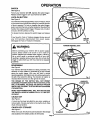
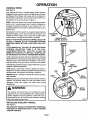
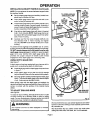
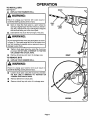
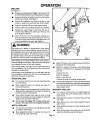
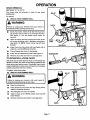
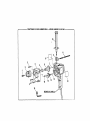
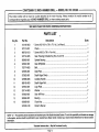
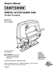
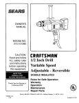
OWNER'S
MANUAL
MODEL NO.
315.101390
CAUTION:
Read and follow
ALL safety rules
and instructions
before operating
this equipment.
Thank You for Buying A
Craftsman Hammer Drill
CRRFTSMRN°
1/2 Inch
Hammer Drill
DOUBLE INSULATED
Rules for Safe Operation
Warranty
Operation
Maintenance
Repair Parts
SEARS, ROEBUCK AND CO., Hoffman Estates,
972000-148
9-00
IL 60179
®
U.S.A.
Printed In U.S.A.
RULES FOR SAFE OPERATION
DOUBLE INSULATION is a concept in safety, in electric
power tools, which eliminates the need for the usual three
wire grounded power cord and grounded supply system.
Wherever there is electric current in the tool there are two
complete sets of insulation to protect the user. All exposed
metal parts are isolated from internal metal motor components
with protecting insulation.
IMPORTANT - Servicing of a tool with double insulation
requires extreme care and knowledge of the system and
should be performed only by a qualified service technician.
For service we suggest you return the tool to your nearest
Sears Store for repair. Always use original factory replacement
parts when servicing.
WARNING:
WARNING:
Do not attempt to operate this tool until you have read
thoroughly and understand completely all instructions,
safety rules, etc. contained in this manual. Failure to
comply can result in accidents involving fire, electric
shock, or serious personal injury. Save owner's manual
and review frequently for continuing safe operation, and
instructing others who may use this tool.
READ
1.
ALL
The double insulated system is intended to protect the
user from shock resulting from a break in the tool's
internal wiring. Observe all normal safety precautions
related to avoiding electrical shock.
moving parts and cause personal injury. Rubber
gloves and non-skid footwear are recommended
when working
outdoors.
Wear protective
hair
INSTRUCTIONS
KNOW
YOUR
POWER
TOOL.
Read
covering to contain long hair and keep it from being
drawn into nearby air vents.
owner's
manual carefully.
Learn its applications
and
limitations as well as the specific potential hazards
related to this tool.
2.
GUARD AGAINST
ELECTRICAL
SHOCK
by
preventing body contact with grounded surfaces.
For example: Pipes, radiators, ranges, refrigerator
enclosures.
3.
KEEP GUARDS
4',
KEEP WQRK AREA
,, benches_,inv_e
IN PLACE
CLEAN.
and in working
Cluttered
11. ALWAYS WEAR SAFETY GLASSES. Everyday
eyeglasses have only impact-resistant lenses; they
are NOT safety glasses.
12.
Don't use
yai
6kEE_-"_H_D_EN
"
AND VISITORS
AWAY. All
'#isitorsbhot_ld _vear safety glasses and be kept a
safe distance frorjn work area. Do not let visitors
contact tool or extension cord.
STORE
should
IDLE
TOOLS.
When
not in use
TOOL.
USE
RIGHT
TOOL.
force
small
tool
limbs or logs.
clothing
PROPER
or jewelry
APPAREL.
Do not wear
that can get caught
hearing
periods of operation.
16.
DON'T OVERREACH.
Keep proper footing and
balance at all times. Do not use on a ladder or
unstable support.
17.
MAINTAIN TOOLS WITH CARE. Keep tools sharp
at all times, and clean for best and safest
performance.
18.
Follow
instructions
for lubricating
loose
DISCONNECT
TOOLS.
When not in use, before
servicing, or when changing attachments,
blades,
bits, cutters, etc., all tools should be disconnected
or
attachment to do the job of a heavy duty tool. Don't
use tool for purpose not intended - for example - A
circular saw should never be used for cutting tree
10. WEAR
Wear
and changing accessories.
It will do the job better and
Don't
HEARING.
SECURE WORK. Use clamps or a vise to hold
work. Both hands are needed to operate the tool.
safer at the rate for which it was designed.
9.
YOUR
15.
be stored in a dry and high or locked-up
DON'T FORCE
PROTECT
DON'T ABUSE CORD. Never carry tool by cord or
yank it to disconnect from receptacle, Keep cord
from heat, oil and sharp edges.
tools
place - out of the reach of children.
8.
Wear a face mask or
14.
_po_er_too_ in'_lamp or wet locations or expose to
K_ep\wo_k area well lit.
7.
LUNGS.
protection during extended
order.
areas and
ENVIRONMENT,
YOUR
dust mask if operation is dusty.
13.
accidents.
5. \ A'_OI_) D_,N(_EROUS
PROTECT
from power supply.
19.
REMOVE
CHUCK
KEY. Form habit of checking
see that chuck key is removed
turning
20.
in tool's
Page 2
AVOID
to
from chuck before
tool on.
ACCIDENTAL
STARTING.
Don't
plugged-in tools with finger on switch.
switch is off when plugging in.
carry
Be sure
RULES FOR SAFE OPERATION
21.
MAKE
SURE
YOUR
EXTENSION
(Continued)
CORD
IS IN
31.
current your product will draw. An undersized cord
will cause a drop in line voltage resulting in loss of
power and overheating.
A wire gage size (A.W.G.)
of at least 16 is recommended
for an extension
22.
OUTDOOR
USE
the gage number,
KEEP
BITS
CLEAN
CORDS.
use only extension
AND
When
cords
SHARP.
Sharp
bits
minimize stalling and kickback.
24.
KEEP
HANDS
AWAY
FROM
DRILLING
34.
NEVER USE IN AN EXPLOSIVE
INSPECT
TOOL CORDS
INSPECT
EXTENSION
KEEP
HANDLES
30.
STAY ALERT.
FOR and remove all nails from lumber
AND
ALCOHOL,
MEDICATION.
Do
not
PLUGS.
To reduce the risk of electric
shock, this tool has a polarized plug (one blade is
wider than the other). This plug will fit in a polarized
outlet only one way. If the plug does not fit fully in
the outlet, reverse the plug. If it still does not fit,
contact a qualified electrician to install the proper
outlet. Do not change the plug in any way.
37.
SAVE
THESE
INSTRUCTIONS.
Review
them
frequently
and use them to instruct others who
may use this tool. If you loan someone this tool,
loan them these instructions also.
PERIODICALLY
CLEAN,
DRUGS,
POLARIZED
and if
WARNING:
FREE
FROM OIL AND GREASE. Always use a clean
cloth when cleaning.
Never use brake fluids,
gasoline, petroleum-based products or any strong
solvents to clean your tool.
29.
INSPECT
36.
ATMOSPHERE.
PERIODICALLY
CORDS
DRY,
LIVE. Do nottouch
WHEN
SERVICING
USE ONLY IDENTICAL
CRAFTSMAN
REPLACEMENT
PARTS.
and replace if damaged.
28.
ELECTRICALLY
35.
damaged, have repaired at your nearest Sears
Repair Center. Stay constantly aware of cord
location.
27.
service center.
operate tool while under the influence of drugs,
alcohol, or any medication.
AREA.
Normal sparking of the motor could ignite fumes.
26.
NOT
the chuck or metal housing when drilling into a
wall; grasp only the insulated handle(s) provided
on the tool.
Keep hands away from bits. Do not reach
underneath work while bit is rotating. Do not attempt
to remove material while bit is rotating.
25.
DOES
DRILLING
INTO ELECTRICAL
WIRING
IN
WALLS CAN CAUSE DRILL BIT AND CHUCK
TO BECOME
33.
suitable for use outdoors. Outdoor approved cords
are marked with the suffix W-A, for example SJ-IW-A or SJOW-A.
23.
IF SWITCH
before drilling.
EXTENSION
tool is used outdoors,
USE TOOL
IT ON AND OFF. Have defective switches
replaced by an authorized
32.
cord 100 feet or less in length. A cord exceeding
100 feet is not recommended.
If in doubt, use the
next heavier gage. The smaller
the heavier the cord.
DO NOT
TURN
GOOD CONDITION.
When using an extension
cord, be sure to use one heavy enough to carry the
Some dust created by power sanding, sawing,
grinding, drilling, and other construction activities
contains chemicals
known to cause cancer, birth
defects or other reproductive harm. Some examples
of these chemicals are:
Watch what you are doing and use
• lead from lead-based
paints,
common sense. Do not operate tool when you are
tired. Do not rush.
• crystalline silica from bricks and cement and other
masonry products, and
CHECK
• arsenic and chromium
lumber.
DAMAGED
PARTS.
Before further use of
the tool, a guard or other part that is damaged
should be carefully checked to determine that itwill
operate properly and perform its intended function.
Check for alignment of moving parts, binding of
moving parts, breakage of parts, mounting, and
any other conditions that may affect its operation.
A guard or other part that is damaged should be
properly repaired or replaced by an authorized
service center unless indicated elsewhere in this
instruction manual.
Page 3
from chemically-treated
Your risk from these exposures varies, depending on
how often you do this type of work. To reduce your
exposure to these chemicals: work in a well ventilated
area, and work with approved safety equipment,
such as those dust masks that are specially designed
to filter out microscopic particles.
INTRODUCTION
CONGRATULATIONS
AND THANK YOU FOR BUYING
THIS CRAFTSMAN
1/2 INCH HAMMER DRILL. It has
been designed, engineered and manufactured to provide
you with Sears high standard of dependability, ease of
operation, and operator safety. Properly cared for, itwill give
you years of rugged, trouble-free performance.
SPECIFICATIONS:
Chuck
1/2 In. Chuck With Chuck Key
5/64 In. To 1/2 In.
Chuck Capacity
Horsepower
CAUTION:
Rating
Carefully read through this entire owner's manual before
using your new hammer drill. Pay close attention to the
Rules For Safe Operation, Warnings and Cautions. If you
use your drill properly and only for what it is intended,
you will enjoy years of safe, reliable service.
Your hammer
operations
performance,
in the design
operate.
3/8
120 Volts, 60 Hz, AC only, 3.5 AMPS
No Load Speed
0 - 1200 RPM
Hammer Speed
0 - 19,200 BPM
Hammer Travel
.025
Switch
Adjustable Variable Speed/Reversible
drill has many features for making your drilling
more pleasant
and enjoyable.
Safety,
and dependability have been given top priority
of this drill making it easy to maintain and
FULL ONE YEAR WARRANTY
ON CRAFTSMAN
HAMMER DRILL
J
If this Craftsman Hammer Drill faits to give complete satisfaction within one year from the date of purchase, RETURN
IT TO THE NEAREST SEARS STORE IN THE UNITED STATES, and Sears will repair it, free of charge.
if this Craftsman Hammer Drill is used for commercial or rental purposes, this warranty applies for only 90 days from
the date of purchase.
This warranty gives you specific legal rights, and you may also have other rights which vary from state to state.
Sears, Roebuck and Co., DEPT. 817 WA, Hoffman Estates, IL 60179
TABLE OF CONTENTS
1.
2.
3.
Rules for Safe Operation ............................................................................
Introduction and Product Specifications .........................................................
Warranty and Table of Contents .....................................................................
2-3
4
4
4
5.
Operation ...................................................................................................
Maintenance and Accessories .....................................................................
5-11
12
6.
7.
Exploded View and Parts List .................................................................
Parts Ordering / Service ...............................................................................
14-15
16
Look
for this
symbol toYour
pointsafety
out important
safety precautions.
It means
attention!!!
is involved,
WARNING:
The operation of any hammer drill can result in foreign objects being thrown into your eyes,
which can result in severe eye damage. Before beginning power tool operation, always wear
safety goggles or safety glasses with side shields and a full face shield when needed. We
recommend Wide Vision Safety Mask for use over eyeglasses or standard safety glasses with
side shields, available at Sears Retail Stores.
Page 4
OPERATION
ELECTRICALCONNECTION
WARNING:
Always wear safety goggles or safer,/glasses with side
shields when operating your hammer drill. Failure to do so
could result in dust, shavings, loose particles or foreign
objects being thrown into your eyes, causing possible
serious injury.
Your hammer drill has a precision built electric motor. It
should be connected to a power supply that is 120 volts,
60 Hz, AC only (normal household current). Do not
operate this tool on direct current (DC). A voltage drop of
more than 10 percent will cause a loss of power end the
motor will overheat. If your tool does not operate when
plugged into an outlet, double-check the power supply.
KNOW YOUR HAMMER DRILL
WARNING:
Before attempting to use your hammer drill, familiarize
yourself with all operating features and safety requirements.
See Figure 1.
Do not allow familiarity with your hammer drill to make you
careless. Remember that a careless fraction of a second
is sufficient to inflict severe injury.
WARNING:
If any parts are missing, do not operate your hammer drill
untilthe missing parts are replaced. Failure to do so could
result in possible serious personal injury.
a
AUXIUARY
HANDLE
DEPTH
GAGEROD
DEPTH
GAGECLAMP,
CHUCKKEY
STORAGEAREA
CHUCK
TO STORE
LOCK-ON
3UTTON
VARIABLESF
CONTROLSELECTOR
SWITCH
TRIGGER
CHUCK
TO REMOVE
Fig. 1
t
Page 5
OPERATION
SWITCH
See Figure2.
To turn your hammer drill ON, depress the switch trigger.
Release switch trigger to turn your hammer drill OFF.
LOCK-ON
BUTFON
See Figure 2.
Your hammer drillis equipped with a "lock-on" feature, which
is convenient when continuous drilling for extended periods
of time is required. To lock-on, depress the switch trigger,
push in and hold the lock-on button located on the side of the
handle, then release switch trigger. Release lock-on button
and your drill will continue running.
To release the lock, depress the switch trigger and release
it.
If you have the "lock-on" feature engaged during use and
your drill becomes disconnected
from power supply,
disengage the "lock-on" feature immediately.
SWITCH
TRIGGER
FORWARD-REVERSELEVER
WARNING:
Before connecting your hammer drill to power supply
source, always check to be sure it is not in "lock-on"
position (depress and release switch trigger). Failure to
do so could result in accidental starting of your drill
resulting in possible serious injury. Also, do not lock the
trigger on jobs where your drill may need to be stopped
suddenly.
i
LOCK-ON
BUTTON
Fig. 2
REVERSE
FORWARD
i
REVERSIBLE
See Figure 3.
Your hammer drill has the feature of being reversible. The
direction of chuck rotation is controlled by a lever located
above the switch trigger. With your drill held in normal
operating position, the rotation lever should be positioned to
the left of the switch for drilling. The direction of rotation is
reversed when the lever is to the right of the switch.
THE DESIGN OF THE SWITCH WILL NOT PERMIT
CHANGING THE DIRECTION OF ROTATION WHILE THE
DRILL IS RUNNING. RELEASE THE SWITCH TRIGGER
AND ALLOW THE DRILL TO STOP BEFORE CHANGING
ITS DIRECTION.
Fig. 3
=l,m
CHUCKKEY
STORAGEAREA
TO STORE
NOTE: YOUR HAMMER DRILL WILL NOT RUN UNLESS
THE SWITCH LEVER IS PUSHED FULLY TO THE LEFT
OR RIGHT.
CHUCK
KEY
See Figure 4.
A chuck key has been provided for use when installing or
removing bits. It is also used when removing the chuck. (See
chuck removal section).
CHUCK
KEY
STORAGE
See Figure 4.
When not in use, the chuck key can be placed in the storage
area located on the bottom portion of drill handle.
_,
Page 6
TO REMOVE
Fig. 4
d
OPERATION
VARIABLE SPEED
See Figure5.
Your hammer drill has a variable speed control selector
designed to allow operator control and adjustment of speed
and torque limits. Speed and torque can be increased or
decreased by rotating the variable speed control selector in
the direction of the arrows shown in figure 5.
NOTE: Hold your hammer drill in normal operating position
and turn the variable speed control selector clockwise to
increase the speed and torque of your hammer drill. Turn
counterclockwise to decrease the speed and torque of your
hammer drill.
If you desire to lock the switch on at a given speed, depress
the switch trigger, push in and hold the lock-on button, and
release the switch trigger. Next, adjust the variable speed
control selector until the desired speed is reached.
NOTE: IF THE VARIABLE SPEED CONTROL SELECTOR
IS FULLY TURNED IN THE COUNTERCLOCKWISE
DIRECTION (ZERO SEI-rlNG) YOUR DRILL MAY NOT
RUN.
FOINCREASE
SPEED
TO DECREASE
SPEED
VARIABLESPEED
CONTROLSELECTOR
IF YOU DESIRE NOT TOJJSE THE VARIABLE SPEED
CONTROL
SELECTOR,
TURN IT IN THE FULL
CLOCKWISE
DIRECTION.
THIS WILL ALLOW THE
SPEED OF YOUR DRILL TO BE FULLY CONTROLLED
BYTHEAMOUNT
OF SWITCH TRIGGER DEPRESSION.
Fig. 5
AUXIUARY
HANDLE
Avoid running your hammer drill at low speeds for extended
periods of time. Running at low speeds under constant usage
may cause your drill to become overheated. If this occurs,
cool your drill by running it without a load and at full speed.
- The following guidelines may be used in determining correct
speed for various applications:
LOW speed is ideal when minimum speed and power is
required. For example: starting holes without center punching,
driving screws, mixing paint, and drilling in ceramics.
MEDIUM speed is suitable for drilling hard metals, plastics,
and laminates.
HIGH speed produces best results when maximum power is
required. For example: drilling in wood; soft metals such as
aluminum, brass, and copper; and when using driving
accessories.
WARNING:
AUXILIARY
TABS
SLOTS
GAGEROD
MOTOR
HOUSING
Your hammer drill should never be connected to power
supply when you are assembling parts, making adjustments, installing or removing drill bits, or when not in use.
Disconnecting your drill will prevent accidental starting
that could cause serious injury.
INSTALLING
DEPTH
GAGECLAMP
HANDLE
See Figure 6.
AN AUXILIARY HANDLE IS PACKED WITH YOUR DRILL
FOR EASE OF OPERATION AND TO HELP PREVENT
LOSS OF CONTROL.
Page 7
Fig. 6
OPERATION
INSTALLING
AUXILIARY
NOTE: For convenience
the auxiliary handle.
HANDLE
(Continued)
TO
TIGHTEN
AUXILIARY
HANDLE
ANDCLAMP
the screw has been trapped inside
•
Remove depth gage clamp and auxiliary handle from
plastic bag in hammer drill box.
•
Orient depth gage clamp so that the tabs will fit into
motor housing of hammer drill,
DEPTH
GAGE
ROD
m . Thread depth gage clamp onto auxiliary handle until it
reaches undercut area of screw threads. Undercut of
screw threads will keep depth gage clamp on auxiliary
handle, preventing it from getting lost.
•
Align tabs on depth gage clamp with slots in threaded
hole in motor housing. NOTE: Depth gage clamp can
be rotated 180 ° so that depth gage rod will fit on either
side of motor housing.
•
Carefully start the fine screw threads (#3/8-24) into
fine threaded hole in motor housing and tighten
securely. DO NOT cross thread handle bolt in motor
housing.
To prevent thread damage and possible loss of control,
auxiliary handle shoul_ be checked periodically fortightness.
DO NOT operate hammer drill with handle loose or with
depth gage clamp removed. In addition to securing depth
gage rod to your hammer drill, depth gage clamp also
provides the proper amount of handle screw thread
engagement when depth gage rod is not being used.
USING
DEPTH
GAGE
Fig. 7
PUSH UP FOR
HAMMERMODE
ROD
See Figure 7.
A depth gage rod has been packed with your hammer drill to
assist you in controlling the depth of drilled holes.
•
Install depth gage rod thru depth gage clamp as shown
in figure 7.
•
Adjust depth gage rod so that the drill bit extends
beyond the end of the rod to the required drilling depth.
•
Securely tighten auxiliary handle against depth gage
clamp. This secures depth gage rod at desired depth
of cut. It also secures auxiliary handle.
When drilling holes with the depth gage rod installed, the
desired hole depth has been reached when the end of the rod
comes in contact with the surface of the material being
drilled.
TO ADJUST DRILLING MODE
PUSHDOWNFOR
DRILLINGMODE
See Figure 8.
To adjust for type of drilling, slide adjustment button on side
of motor housing up to hammer mode or down to drilling
mode. For your convenience a hammer symbol and drill bit
symbol have been molded into adjustment button.
WARNING:
Fig.
We recommend that you use carbide-tipped bits and selecl
hammer mode when drilling in hard materials such as brick,
tile, concrete, etc.
We recommend that you select normal drill mode when
drilling with twist drills, hole saws, etc. in soft materials.
Page 8
OPERATION
TO INSTALL
BITS
See Figure 9.
•
CHUCK
\
UNPLUG YOUR HAMMER DRILL.
Failure to unplug
your hammer
drill could
result in
accidental starting causing serious injury.
•
Open or close the chuck jaws to a point where the
opening is slightly larger than the drill bit you intend to
use. Also, raise the front of your drill slightly to keep the
drill bits from falling out of the chuck jaws.
•
Insert drill bit into chuck the full length of the jaws.
DRILL
BIT
CHUCK
JAWS
WARNING:
Do not insert drill bit into chuck jaws and tighten as shown
in figure 10. This could cause drill bit to be thrown from
your drill resulting in possible serious personal injury or
damage to your chuck.
•
Tighten chuck jaws'securely,
using the chuck key
provided. DO NOT USE A WRENCH TO TIGHTEN
OR LOOSEN THE CHUCK JAWS.
•
Remove chuck key and return to storage area.
TO REMOVE
•
RIGHT
Fig. 9
BITS
UNPLUG YOUR HAMMER DRILL.
WARNING:
Failure to unplug your hammer drill could result in
accidental starting causing serious injury.
]
•
Loosen chuck jaws using the chuck key provided.
DO NOT USE A WRENCH
TO TIGHTEN OR
LOOSEN THE CHUCK JAWS.
•
Remove drill bit from chuck jaws.
•
Remove chuck key and return it to storage area.
Page 9
OPERATION
DRILLING
See Figure 1 I.
•
Depress and release switch trigger to be sure your drill
is in OFF position before connecting it to power supply.
•
Check the direction of rotation lever for correct setting
(forward or reverse). See Figure 3.
•
Secure the material to be drilled in a vise or with
clamps to keep it from turning as the drill bit rotates.
•
Plug your hammer drill into power supply source.
•
Hold your drill firmly and place bit at point to be drilled.
•
Depress the switch trigger to start your drill. De not
lock the switch ON for jobs where your drill may need
to be stopped suddenly.
•
Move the drill bit into the workpiece applying only
enough pressure to keep the bit cutting. Do not force
your drill or apply side pressure to elongate a hole. Let
your drill and bit do the work. See Figure 11.
WARNING:
Be prepared for bilqding or breakthrough. When these
situations occur, drill has a tendency to grab and kick in
the opposite direction and could cause loss of control when
breaking through material. This loss of control can result
in possible serious injury. Do not lock the trigger on jobs
where your drill may need to be stopped suddenly.
Fig. t 1
i
When drilling hard, smooth surfaces use a center punch to
mark the desired hole location. This will prevent the drill bit
from slipping off center as the hole is started.
When drilling metals, use a light oil on the drill bit to keep it
from overheating. The oil will prolong the life of the bit and
increase the drilling action.
•
Begin drilling at a very low speed to prevent the bit fron
slipping off the starting point.
•
Maintain a speed and pressure which allows cuttin(.
without overheating the bit. Applying too much pres
sure will:
If the bit jams in the workpiece or if your drill stalls, stop the
tool immediately. Remove the bit from the workpiece and
determine the reason for jamming.
Overheat the drill;
Wear the bearings;
Bend or burn bits; and
WOOD DRILLING
Produce off-center or irregular shaped holes.
•
For maximum performance use high speed steel bits
for wood drilling.
•
Slide adjustment button on hammer drill down for
normal drilling action.
•
Begin drilling at a very low speed to prevent the bit from
slipping off the starting point. Increase the speed as
the drill bit bites into the material.
•
•
•
MASONRY
DRILLING
•
For maximum performance use carbide-tipped ma
sonry impact bits when drilling holes in brick, tile
concrete, etc.
•
Slide adjustment button on hammer drill up for ham
mer mode.
•
Apply light pressure and medium speed for best re
suits in brick.
•
Apply additional pressure for hard materials such a,'
concrete.
•
Slide adjustment button on hammer drill down for
normal drilling action (drill mode).
Page 10
When drilling holes in tile, practice on a scrap piece t(
determine the best speed and pressure.
When drilling through holes, place a block of wood
behind the workpiece to prevent ragged or splintered
edges on the back side of the hole.
Do not lock the trigger ON for jobs where your
hammer drill may need to be stopped suddenly.
METAL
•
When drilling large holes in metal, we recommend tha
you drill with a small bit first, then finish with a larger bil
Also, lubricate the bit with oil to improve drilling actior
and increase bit life.
DRILLING
For maximum performance
for metal or steel drilling.
use high speed steel bits
OPERATION
CHUCK REMOVAL
See Figures 12, 13, and 14.
The chuck must be removed
accessories.
in order to use some
To remove:
•
UNPLUGYOUR
HAMMER DRILL.
Failure to unplug your hammer drill could result in
accidental starting causing serious injury.
•
Close chuck jaws. Insert chuck key into chuck and
tap sharply with a mallet in a clockwise direction.
See figure 12. This will loosen chuck screw for
removal•
•
Open the chuck jaws and remove the chuck screw
by turning clockwise with a flatblade screwdriver.
See figure 13. NOTE: Chuck screw has left hand
threads.
•
insert chuck key into chuck and tap sharply with a
mallet on a counterclockwnse durectlon.
•
This will loosen the chuck on the spindle.
•
It can now be unscrewed by hand. See Figure 14.
•
Remove chuck key and return to storage area.
TO RETIGHTEN
A LOOSE CHUCK
The chuck may at times become loose on the spindle and
develop a wobble. Also, after several drilling operations the
chuck screw may become loose. Periodically check chuck
screw for tightness. A loose screw will cause the chuck jaws
to bind and prevent them from closing.
Fig. 13
To tighten, follow these steps:
•
UNPLUG YOUR HAMMER DRILL.
IA
| Failure to unplug your hammer
drill could
MALLET
result in
I accidental starting causing serious injury.
I
•
Open the chuck jaws.
•
Insert chuck key into chuck and tap sharply with a
mallet in clockwise direction.
•
This will tighten the chuck on spindle.
•
Tighten chuck screw. NOTE: Chuck screw has left
hand threads.
•
Remove chuck key and return to storage area.
Page 11
\
MAINTENANCE
It has been found that electric tools are subject to accelerate
wear and possible premature failure when they are used c
fiberglass
boats, sports cars, wallboard, spacklin
compounds, or plaster. The chips and grindings from thee
materials are highly abrasive to electric tool parts such a
bearings, brushes, commutators, etc. Consequently, itis nr
recommended that this tool be used for extended work o
WARNING:
When servicing use only identical Craftsman replacement
parts. Use of any other parts may create a hazard or cause
product damage.
GENERAL
Only the parts shown on parts list, page 15, are intended to
be repaired or replaced by the customer. All other parts
represent an important part of the double insulation system
and should be serviced only by a qualified Sears service
technician.
Avoid using solvents when cleaning plastic pads. Most
plastics are susceptible to damage from various types of
commercial solvents and may be damaged by their use. Use
clean cloths to remove dirt, carbon dust, etc.
any fiberglass material, wallboard, spackling compounds, (
plaster. During any use on these materials, it is extremel
important that the tool is cleaned frequently by blowing wit
an air jet.
WARNING:
Always wear safety goggles or safety glasses with side
shields during power tool operation or when blowing dust.
If operation is dusty, also wear a dust mask.
WARNING:
Do not at any time let brake fluids, gasoline, petroleum-based products, penetrating
plastic parts. They contain chemicals that can damage, weaken, or destroy plastic.
oils, etc. come in contact with
I
ACCESSORIES
THE FOLLOWING RECOMMENDED ACCESSORIES ARE CURRENTLY
AVAILABLE AT SEARS RETAIL STORES.
High Speed Bits (For wood or metal)
1/2 In. Max.
Hole Saws
Masonry Bits
3/4 In. Max.
1/2 In. Chuck (.9_-2980)
Wood Boring Bits
_k
WARNING:
EXTENSION
2-1/2 In. Max.
1-1/2 In. Max.
The use of attachments or accessories
not listed above might be hazardous.
CORDS
WARNING:
The use of any extension cord will cause some loss of power.
To keep the loss to a minimum and to preventtool overheating,
use an extension cord that is heavy enough to carry the
current the tool will draw.
Check extension cords before each use. If damaged
replace immediately. Never use tool with a damaged cord
since touching the damaged area could cause electrical
shock resulting in serious injury.
A wire gage size (A.W.G.) of at least 16 is recommended for
an extension cord 100 feet or less in length. When working
outdoors, use an extension cord that is suitable for outdoor
use. The cord's jacket will be marked WA.
LUBRICATION
CAUTION:
Keep extension cords away from the drilling area and
position the cord so that it will not get caught on lumber,
tools, etc. during drilling operation.
All of the bearings in this tool are lubricated with a sufficien
amount of high grade lubricant for the life of the unit unde
normal operating conditions. Therefore, no further lubricatior
is required.
i
Page12
NOTES
m
Page 13
CRAFTSMAN 1/2 INCH HAMMER DRILL--
MODEL NUMBER 315.101390 ...........
lp
11
15
13
14
3
SEE NOTE _A" PAGE
13
12
CRAFTSMAN
1/2 INCH
HAMMER
DRILL-
MODEL
NO. 315.101390
(
The model number will be found on a plate attached to the motor housing. Always mention the model number in all
correspondence regarding your 1/2 INCH HAMMER DRILL or when ordering repair parts.
SEE BACK PAGE FOR PARTS ORDERING INSTRUCTIONS
PARTS LIST
Key No.
Description
PaN No.
1
613150-003
2
Quan.
973110-001
Screw (#5/16-24 x 7/8 In. Fil. Hd., Left Hand) .....................................................
Chuck ..................................................................................................................
1
1
3
968703-013
Screw (#8-32 x 7/8 In. Pan Hd.) ..........................................................................
4
4
972724-005
Gear Housing
1
5
990963-001
Spindle
Bearing
..................................................................................................
1
6
972927-001
Gear W/Spindle
..................................................................................................
1
7
703774-005
Ball ......................................................................................................................
1
8
972925-001
Data Plate ...........................................................................................................
1
9
973825-001
Depth Gage Clamp .............................................................................................
1
10
972895-006
Auxiliary
Handle ..................................................................................................
1
11
886165-000
Depth Gage Rod .................................................................................................
1
12
972924-001
13
931744-063
Logo Plate ...........................................................................................................
Washer ...............................................................................................................
1
2
14
972823-001
Gear W/Pinion
1
15
990962-001
Bearing
16
606858-001
Chuck Key ..........................................................................................................
972000-148
Owner's
(Includes
Key Nos. 5 and 15) ......................................................
....................................................................................................
...............................................................................................................
1
1
Manual
NOTE: "A"-- The assembly shown represents an important part of the Double Insulated System. To avoid the possibility of alteration or damage
to the system, service should be performed by your nearest Sears Repair Center. Contact your nearest Sears Retail Store for Service Center
information.
* Standard Hardware Item -- May Be Purchased Locally.
t=
Page 15
For repair of major brand appliances in your own home...
no matter who made it, no matter who sold it!
1-800-4-MY-HOME
sMAnytime,
day or night
(1-800-469-4663)
www.sears.com
:'
To bring in products such as vacuums, lawn equipment and electronics
for repair, call for the location of your nearest Sears Parts & Repair Center.
1-800-488-1222
Anytime,
day or night
www.sears.com
For the replacement parts, accessories and owner's manuals
that you need to do-it-yourself, call Sears PartsDirect sM!
1-800-366-PART
Bar.- 11pm CST,
(1-800-366-7278)
7 days a week
www.sears.com/partsdirect
To purchase or inquire about a Sears Service Agreement:
1-800-827-6655
7 a.m. - 5 p.m. CST, Mon. - Sat.
Para pedir servicio de reparaci6n a domicilio,
y para ordenar piezas con entrega a domicilio:
1-888-SU-HOGAR
Au Canada pour service en fran£ais:
1-877-LE-FOYERS"
s.
(1-877-533-6937)
(1-888-784-6427)
SEARS
]
HomeCentral" J
® Registered Trademark / T. Trademark of Seam, Roebuck and Co.
O Sears, Roebuck and Co,
® Marca Registrada / TM Marca de Fdbrica de Sears, Roebuck and CO,