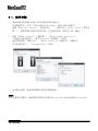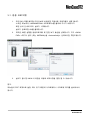
1
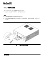
MonCaso 972 series Product Guide ENGLISH Please read this manual carefully before system installations. MonCaso 972 series product guide Manual Rev: 2.0 Release Date: November. 2008 Copyright ⓒ 2008 Moneual Inc. All Rights Reserved. No parts of this manual, including the products and software describe in it, may be reproduced, transmitted, transcribed, and stored in retrieval system, or translated into any language in any form or by any means, except documentation kept by the purchaser for backup purpose, without the express written permission of Moneual Lab (Moneual). Product warranty or service will not extended if: (1) the product is repaired, modified or altered, unless such repair, modification or alteration is authorized in writing by Moneual; or (2) the serial number of the product is defaced or missing. Moneual provides this manual "as is" without warranty of any kind, either express or implied, including but not limited to the implied warranties or conditions of merchantability or fitness for a particular purpose. In no event shall Moneual, its directors, officers, employees or agents be liable for any indirect, special, incidental, or consequential damages (including damages for loss of profits, loss of business, loss of use or data, interruption of business and the like), even if Moneual has been advised of the possibility of such damages arising from any defect or error in this manual or product. Specifications and information contained in this manual are furnished for informational use only, and are subject to change at any time without notice, and should not be construed as a commitment by Moneual. Moneual assumes no responsibility or liability for any errors or inaccuracies that may appear in this manual, including the products and software described in it. Products and corporate names appearing in this manual may or may not be registered trademarks or copyrights of their respective companies, and are used only for identification or explanation and to the owners' benefit, without intent to infringe. Revision History Revision V1.0 V1.1e V2.0 2 ENGLISH Date January. 2008 July. 2008 Novemver.2008 Contents Safety information ..........................................................................................................5 Drawing of Dismantlement .............................................................................................6 Package Contents ..........................................................................................................7 Specification of Product ..................................................................................................8 Chapter 1. Introduction ................................................................................... 9 1-1. Introduction ...........................................................................................................10 1-2. Front panel ............................................................................................................10 1-3. Rear panel .............................................................................................................12 Chapter 2. Installation Guide ....................................................................... 13 2-1. Before You Begin ..................................................................................................14 2-2. Opening the Case .................................................................................................15 2-3. Installing HDD .......................................................................................................16 2-4. Installing ODD .......................................................................................................17 2-5. Installing Motherboard ........................................................................................... 18 2-6. Installing Power Supply Unit .................................................................................. 19 2-7. Cable Connection ..................................................................................................20 2-8. Power S.W and LED Connection ..........................................................................20 2-9. iMON LCD Connection .......................................................................................... 21 2-10. Front I/O& Card Reader Connection ...................................................................22 2-11. RGB Terminal Connection .................................................................................. 23 2-12. Attaching ODD Bezel .......................................................................................... 24 2-13. Installing the wireless keyboard ..........................................................................25 Chapter 3. PAD Remote Control Software Installation ........................... 27 3-1. Software Installation .............................................................................................. 28 Service Notice...............................................................................................29 ENGLISH 3 4 ENGLISH ▪ Safety information Electrical safety 1. To prevent electrical shock hazard, disconnect the power cable from the electrical outlet before relocating the system. 2. When adding or removing devices to or from the system, ensure that the power cables for the devices are unplugged before the signal cables are connected. 3. If the power supply is broken, do not try to fix it by yourself. Contact a qualified service technician or your retailer. Operation safety 1. Before installing devices into the system, carefully read all the documentation that came with the package. 2. Before using the product, make sure all cables are correctly connected and the power cables are not damaged. If you detect any damage, contact your dealer immediately. 3. To avoid short circuits, keep paper clips, screws, and staples away from connectors, slots, sockets and circuitry. 4. Avoid dust, humidity, and temperature extremes. Don not place the product in any area where it may become wet. Place the product on a stable surface. 5. If you encounter technical problems with the product, contact a qualified service technician or your retailer. Disclaimer Moneual Inc is not responsible for any damages due to external causes, including but not limited to, improper use, problems with electrical power, accident, neglect, alteration, repair, improper installation, or improper testing. ENGLISH 5 ▪ Drawing of Dismantlement Figures... Drawing of Dismanglement Tables...Drawing of Dismanglement 1.Front Panel 2.Side 3.Base Plate 4.Rear Plate 5.Top Cover 6.HDD Cage 7.ODD Cage 8.PSU Guide 9.Hand Screw (#6-32) 10.Door 11.Punching Metal 12.Slot Guide-S 13.Audio Foot 14.DVD Bezel 15.Power Button 16.Vol.Knob 17.10Key button 18.Card Reader Cover 19.Card Reader 20.Rear FAN 24.LCD Frame 25.7"Touch LCD 21.HDD FAN(Optional) 22.PCI Bracket 6 ENGLISH 23.LCD Cover ▪ Package Contents Check your MonCaso 972 series package for the following items. If any of the below items is damaged or missing, contact your retailer immediately. Case Accessories Item iMON 7"LCD 2 Screw driver 1 Support Screw (M3*5*3L) Washer Head Screws (M3*5L) 2 20 HDD Screw (#6-32*5L) 8 ODD Bezel Stylus Pen 1 1 User's Guide 1 Item iMON Remote Control (PAD Type) iMON Power Cable(20pin-24pin) AAA batteries for Pad Remote Control Driver CD Wireless Keyboard (optional) Q'ty Hand Screw (#6-32*5) Item Q'ty 1 1 1set 1 Q'ty Wireless keyboard 1 USB receiver 1 USB extend cable AAA battery Keyboard driver CD 1 1set 1 (Wireless Keyboard is optional component) The specifications and package contents of product may change without prior notice to improve performance. ENGLISH 7 ▪ Specification of Product Specifications Case Type Desktop Dimensions 460(L) x 435(W) x 160(H) mm Weight 7kg (15.43 lb) Material Aluminum Form Factor Standard ATX / micro ATX Power Supply Standard ATX PCI/AGP Size Full Size 5.25" Bays 1 x 5.25" External Drive Bay 3.25 Bays 4 x 3.5" Internal Drive Bays Expansion Slots 7 Slots FAN Slots 4 Slots (HDD Cage: 2x80mm / Rear Plate: 2x80mm) FAN Included Rear Plate: 2 x 80mm*25T FAN Front I/O Ports 1 x USB Ports, 1 x IEEE1394 (Firewire) Port, 1 x Microphone, 1 x Headphones Case Colors Silver / Black Compatible cards Card Reader (7 in 1) 7" Touch LCD 8 ENGLISH Compatible OS Host interface Power Supply Screen Size Screen Ratio Maximum Resolution Screen Output Power Input Touch Screen : CF(I/II), Micro Drive, SmartMedia, MultiMedia, SecureDigital and Memory stick. : Microsoft windows 98/ME/2000/XP : USB 2.0 ports : DC 5V +/-5%, through USB port : 7" Wide LCD : 15:9 : 1024 x 768 : D-Sub : 12V DC Chapter 1 Introduction This chapter gives a general description of the MonCaso series. The chapter lists the system features including introduction on the front panel, rear panels, and internal components. ENGLISH 9 1-1. Introduction Thank you for choosing the MonCaso series Home Theater PC Case. The MonCaso 972 series will make you experience a perfect multimedia world. The MonCaso 972 series is designed to be fully compatible with the world’s best hardware components and provides quiet computing environment with its patented airflow structure and cooling system. Its refined exterior design with full premium aluminum chassis and built-in 7” LCD touch screen display matching up with your other AV system arrangements will greatly contribute to the overall impression of your living room. Especially, universal wireless remote control unit that comes with the case will give you more convenient control wherever you are at home. MonCaso 972 series will deliver the leading edge technology for your computing and multimedia entertainment needs. 1-2. Front panel 1. System power button: Press this button to turn the system on. 2. IR receiver: This receives signals from the MonCaso PAD remote control. 3. Microphone port: This port connects microphone. 4. Headphone port: This port connects a headphone with a stereo mini-plug. 10 ENGLISH 5. 6-pin IEEE 1394 port: The IEEE 1394 high-speed serial bus complements USB by providing enhanced PC connectivity for a wide range of devices, including audio/video (A/V) appliances, storage peripherals, other PCs and portable devices. 6. USB 2.0 port: This Universal Serial Bus 2.0 (USB 2.0) port is available for connecting USB 2.0 devices such as a mouse, printer, scanner, camera, PDA, and others. 7. LCD touch screen: This is a 7” LCD touch screen. NOTE Dual display graphics card should be used for LCD touch screen. 8. ODD bezel: This bezel is to be attached to ODD tray. Refer on page 28 about how to install bezel on ODD tray. 9. ODD tray eject button: Press this button to eject the optical drive tray. 10. Control buttons - Direct button (MCE): This allows to go to the application program directly. It can be user-defined. - App.Exit button: This quits the application program. It works same as "ALT+F4" - Back space button: This is used to go backward on MCE or iMEDIAN. - Direction button: This is arrow key to move up/down/left/right. - Start button: This is same as the windows icon key on the keyboard. - Menu button: This is same as the menu button of the MonCaso PAD remote controller. 11. Volume control/mute button: This is used for volume up and down/pressing for mute. 12. Power LED: This LED lights up when you place a storage card in any of the card slots, and turn off when you remove the card. 13. Card slot activity (W/R) LED: This LED flashes when data is being read from or written to a storage card inserted any of the storage card slots. 14. Memory Stick/Memory Stick Pro card slot: This slot is for a Memory Stick/Memory Stick Pro storage card. 15. Secure Digital/Multimedia Card slot: This slot is for a Secure Digital/Multimedia Card storage card. 16. Compact Flash /Microdrive card slot: This slot is for a Compact Flash /Microdrive storage card. 17. Smart Media card slot: This slot is for a Smart Media storage card. ENGLISH 11 1-3. Rear panel 1. Space for power supply 2. Thumbscrew: These thumbscrews secure the top cover to the chassis. 3. Motherboard I/O shield hole: Space for I/O port from motherboard 4. Air vent: Space for air flow-out. It causes system failure if you block this air vent. 5. PCI bracket: Remove bracket gently when you install graphics card or PC peripherals. 6. RGB terminal: This cable is connected to the RGB port of the graphics card. This is used for LCD touch screen display. NOTE Dual display graphics card should be used for LCD touch screen. 12 ENGLISH Chapter 2. Installation Guide This chapter provides step-by-step instruction on how to install components in the case. ENGLISH 13 2-1. Before You Begin Installation Precautions When you install and test the MonCaso 972 series system, observe all warnings and cautions in the installation instructions. To avoid injury, be careful of: Sharp pins on connectors Sharp pins on printed circuit assemblies Rough edges and sharp corners on the chassis Hot components (like processors, voltage regulators, and heat sinks) Damage to wires that could cause a short circuits Observe all warnings and cautions that instruct you to refer computer servicing to qualified technical personal. Prevent Power Supply Overload Do not overload the power supply output. To avoid overloading the power supply, make sure that the calculated total current loads of all the modules within the computer is less than the output current rating of each of the power supplies output circuits. Observe Safety and Regulatory Requirements Read and adhere the instructions in this section and the instructions supplied with the chassis and associated modules. If you do not follow these instructions and the instruction provided by the chassis and module suppliers, you increase safety risk and the possibility of noncompliance with regional laws and regulations. If the instructions for the chassis are inconsistent with the instructions for associated modules, contact the supplier’s technical support to find out how you can ensure that your computer meets safety and regulatory requirements. 14 ENGLISH 2-2. Opening the Case CAUTION Do not remove the two bolts on the top cover near the front of the case. Step1. Remove the Hand screw(#6-32) at the back of the top cover. Step2. Slide back and lift top cover to open. HAND SCREW (#6-32) STEP1. STEP2. ENGLISH 15 2-3. Installing HDD Step1. Using the Included screwdriver, remove all the screws indicated in the figure STEP1. and removed the HDD bracket. Step2. Secure the HDD disks to the HDD bracket as shown in figure STEP2. NOTE. The HDD FAN (80mm*25T) is an optional part and may not be included in your case. STEP1. STEP2. 16 ENGLISH 2-4. Installing ODD Step1. Using the included screw driver, remove all the screws indicated in the figure STEP1. and remove the ODD bracket. Step2. Secure the ODD drive within the ODD bracket. NOTE. The 972 Case's ODD Drive is attached very close to the Main Board and may cause problems if it is too big. Make sure to check specs before purchasing an ODD drive. STEP1. Tip. ODD Bezel Removal You can manually open the ODD by using a clip to press a small button inside the hole in the front. The bezel can be removed by lifting up by the bottom. CAUTION The use of force may cause damages. If your ODD does not instantly and easily remove itself, please contact the ODD manufacterer. STEP2. CAUTION It is not possible to install ODD that the depth is over 170mm. Be sure to check the ODD specification before purchasing ODD. ENGLISH 17 2-5. Installing Motherboard Refering to the figure below, use the Washer Head Screws (M3*5L) to secure the Motherboard after determining the right stand off spaces according to the Form Factor chart below. Form Factor Mounting hole locations ATX A, E, I, C, G, J, D, H, K micro-ATX B, C, D, F, G, H, J, K Key, mounting holes microATX ● ATX ○ NOTE. The ATX is the default Form Factor for the 972 Case. Support screw(M3*5*3L) CAUTION The ATX is the default Form Factor for the 972. To use a mATX make sure to insert Support Screw(M3*5*3L) into B,F before using. To eliminated the chance of short circuiting after exchanging to ATX from a mATX, make sure to remove all Support Screws (M3*5*3L). 18 ENGLISH 2-6. Installing Power Supply Unit Step1. Remove the PSU Guide before attaching the Power Supply. Step2. After positioning the Power Supply so the Fan is facing the case's Side Vent Hole, use Screw(#6*32) to attach to the case. Attach the PSU Guide after Installing the Power Supply to protect the Power Supply from external impact. The flow of air initiated by the Side Vent Hole STEP2. STEP1. PSU Guide ENGLISH 19 2-7. Cable Connection Figure... Front Panel Inside View Table... Front Panel Inside View A. S.W B/D B. Front I/O B/D C. Card Reader E. 10key B/D F. Vol. Knob B/D G. IR Receiver D. 7" LCD Module 2-8. Power S.W and LED Connection 1. Connect the S.W B/D's Power S.W cable to the iMON LCD's Power In 2Pin. 2. Connect the iMON LCD's Power out 2Pin cable to the front port of the motherboard with the Power S.W pin. 3. Connect the S.W B/D's LED cable with the MotherBoard's front port LED Pin. * Refer to the manual that came with the MotherBoard for more information on the front ports. * Make sure that all connections are made in the correct direction. Motherboard LED Port 2Pin or 3Pin 20 ENGLISH Motherboard Power Port 2-9. iMON LCD Connection Connect the iMON Power Cable to the Power Supply's 24Pin or 20Pin Connector. Step1. After Connecting, connect the iMON LCD Power Cable's opposite connector to the motherboard's 24Pin or 20Pin connector. Connect the iMON LCD Power Cable's iMON LCD Power 4Pin Connector to the iMON LCD main B/D's 4PinConnector. NOTE. The iMON LCD Power Cable connects to a 24Pin or 20Pin Connector. Refer to the MotherBoard's manual to find the location of the Power cable. Connect the iMON LCD's USB Cable to the MotherBoard's USB Port. NOTE. Refer to the MotherBoard's manual to find the location of the MotherBoard's USB Connector. When connecting the internal USB Connector, refer to the USB2.0 Header Signal Names in Figure1. to determine the correct directions. Motherboard Power 24Pin Connector CAUTION Connecting the USB connectors in the wrong direction may cause damage to parts. Figure... iMON LCD Power Cable Connection ENGLISH 21 2-10. Front I/O& Card Reader Connection Front I/O Connection After determining the location of the MotherBoard's connector, Connect with the Front I/O in the correct direction. Card Reader Connection After locating the MotherBoard's Connector connect with the Card Reader in the correct direction. NOTE. The location of the USB2.0 / IEEE1394 / Audio Ports can be found in the MotherBoard's manual. CAUTION Plugging connectors in the wrong direction can damage the parts. Figure... iMON LCD Power Cable Connection 22 ENGLISH 2-11. RGB Terminal Connection Install a Graphic Card that support a Dual Display. Using the Graphic Card's Manual as reference, connect the RGB cables for the Main Moniter and Sub Moniter (7'' LCD) to the Graphic Card. After installing the OS, Refer to the Graphic Card's Manual to set up the dual display. NOTE. When purchasing a Graphic Card for the 7'' LCD display, make sure to purchase one that supports Multiple screens/Dual Display. Usually, the port on the top of the Graphic Card is the Secondary port. However, This may differ per brand according to the specs of each Graphic Card. The 7"LCD's RGB Terminal is a D-Sub port. When connecting the DVI, use the DVI to D-Sub adapter to connect. In order to use the 7"LCD in Front View mode, It must be set up on Dual Display mode. Refer to the Graphic Card's Manual to set up this mode. Any problems or errors that occur whilt setting up this mode may have to be taken to the Graphic Card manufacturer. Figure... iMON LCD Power Cable Connection ENGLISH 23 2-12. Attaching ODD Bezel Once the system is installed and powered on, press the ODD button to open. Remove the tape on the back of the included OCC bezel and attach it into the tray. NOTE. Removal directions for the ODD Bezel can be found on Page 17. Should the ODD's plastic bezel not remove itself easily, do not try to remove by force. Refer the problem to the ODD manufacterer. Figure... iMON LCD Power Cable Connection 24 ENGLISH (Wireless Keyboard is optional component) 2-13. Installing the wireless keyboard Plug the USB receiver to the USB port of the front or rear panel of MonCaso 972 system. USB extension cable can be used to connect the USB receiver. Install the keyboard batteries. Press the connect button on the USB receiver. Turn on the on/off switch on the front side of keyboard. Press the "Connect" key under the keyboard. NOTE. If the keyboard does not work suddenly, press the trackball of the keyboard or reset "Connect" key. ENGLISH 25 26 ENGLISH Chapter 3. PAD Remote Control Software Installation ENGLISH 27 3-1. Software Installation 1. Insert the driver CD into the optical drive then it will run automatically. On the screen menu, click "iMON/iMEDIAN Software". Select "Read the contentsand click 'Start Setup'. Follow the onscreen instructions to begin the installation, when setup is completed, click OK. 2. Select Remote control, Quick Launch Application and FrontView option. It is recommend to choose "iMON PAD"Media Center (or iMEDIAN)", "Automaticallyrespectively. 3. When the installation finished, use the iMON icon for more specific setting. NOTE. Adobe Acrobat Reader or Adobe Acrobat need to be installed in your system because manual is described as PDF format. 28 ENGLISH ▐ Service Notice Free after-sales service for hardware of the product is guaranteed for a year. However, free-of-charge warranty does not applied to any breakage and defect caused by consumer’s mistakes or force majeure. * Purchase in Korea After-sales Service through Lemon Service TEL: 1577-1475 Service Center Availability Monday ~ Friday Saturday Sunday and public holiday are not available. * Purchase in North America & South America Service Center Telephone: 1-949-450-0105 Service Center Available Time: Monday ~ Friday 09:00‾18:00 Saturday and public holiday are not available. Technical Support E-mail: [email protected] * For purchase in China, Europe and other areas, contact your local agency. Manufacturer: Moneual Inc. 611, Kolon Digital Tower Villant 2, 222-8, Guro-dong, Guro-gu, Seoul, Korea TEL: 82-2-2081-2100 ENGLISH 29 30 ENGLISH MonCaso 972系列 产品指南 Chinese 请在进行系统安装之前仔细阅读本手册. 安全信息 ...................................................................3 其他信息 ...................................................................3 拆卸图示 ...................................................................4 包装内容 ...................................................................5 产品规格 ...................................................................6 第 1 章 简介 ..................................................... 7 1-1. 简介 ..................................................................8 1-2. 前置面板 ..............................................................8 1-3. 后置面板 ............................................................. 10 第 2 章 安装指南 ................................................. 11 2-1. 安装警示 ............................................................. 12 2-2. 打开机箱 ............................................................. 13 2-3. 安装硬盘 ............................................................. 14 2-4. 安装光驱 ............................................................. 15 2-5. 安装主机板 ........................................................... 16 2-6. 安装电源单元 ......................................................... 16 2-7. 连接电线 ............................................................. 18 2-8. 电源开关和指示灯连接 ................................................. 18 2-9. 连接iMON液晶显示屏 ................................................... 19 2-10. 连接前置输入/输出接口和读卡器 ....................................... 20 2-11. 连接RGB终端 ......................................................... 21 2-12. 安装光驱盖板 ........................................................ 22 2-13. 安装无线键盘 ........................................................ 23 第 3 章 PAD遥控器 软件安装 ...................................... 25 3-1. 软件安装 ............................................................. 26 服务介绍 2 CHINESE „„„„„„„„„„„„„„„„„„„„„„„„„„„„27 安全信息 电气安全 1. 要防止电击危险,请在重新定位系统之前将电源线从电源插座上拔下。 2. 当将设备加至系统或将其从系统中删除时,请确保在连接信号电线之前拔下设 备电源线。 3. 如果电源受损,请勿尝试自行修理。请联系通过认证的维修技术人员或您的零 售商。 操作安全 1. 将设备安装至系统中之前,请仔细阅读包装中随附的所有文件。 2. 在使用产品之前,请确保已正确连接所有的电线,并确定电源线没有损坏。如 果发现任何损坏,请立即联系您的经销商。 3. 要避免短路,请勿将纸夹、螺钉和订书钉靠近连接器、插槽、插座和电路放 置。 4. 避免灰尘、潮湿以及极端温度环境。请勿将产品放置在任何容易受潮的地方。 将产品置于稳固的表面上。 5. 如果产品遇到技术方面的问题,请联系通过资格认证的维修技术人员或您的零 售商。 免责声明 Moneual Lab对任何由于外部原因导致的损害不承担责任,包括但不限于不当使 用、电力问题、意外事件、疏忽、改造、修理、不当安装或不当测试。 其他信息 有关其他信息以及产品和软件的更新,请参考以下消息来源。 1. 技术支持 有关驱动程序更新和其他信息,请访问Moneual网站: www.moneual.com. 联系技术人员:[email protected] / Tel. 949-458-1022 2. 可选文件 您的产品包装中可能包括可选文件(例如保修单),它们可能是由经销商放入的。 标准包装中不包含这些文件。 CHINESE 3 拆卸图示 图...拆卸图示 表...拆卸图示 1.前置面板 2.侧面板 3.底板 4.后置面板 5.顶盖 6.硬盘架 7.光驱架 8.电源指引 9.手拧螺钉(#6-32) 10.护盖 11.冲压金属侧盖 12.导向槽架 13.音频脚 14.光盘盖板 15.电源按钮 16.音量旋钮 17.10键按钮 18.读卡器护盖 19.读卡器 20.后置风扇 23.液晶显示屏护壳 24.液晶显示屏支架 25.7吋触摸式液晶显示屏 21.硬盘风扇(可选) 22.PCI插槽 4 CHINESE 包装内容 请检查您的MonCaso 972系列包装中是否包含以下项目。 如果发现以下任意一项受损或缺失,请立即与零售商联系。 机箱附件 iMON 7吋液晶显示屏 项目 手拧螺钉(#6-32*5) 螺钉起子 1 支承螺钉(M3*5*3L) 凸缘螺钉(M3*5L) 2 20 硬盘螺钉(#6-32*5L) 8 光驱盖板 1 手写笔 用户指南 1 1 项目 iMON 遥控器(PAD式) iMON 电源线(20针至24针) 用于PAD遥控器的AAA电池 驱动程序光盘 无线键盘(可选) 数量 2 数量 1 1 1套 1 项目 无线键盘 数量 1 USB接收器 1 USB延长线 AAA电池 键盘驱动程序光盘 1 1套 1 (无线键盘是可选配件) 为了提高产品性能,可能会变更产品的规格以及包装内容,恕不事先通知。 CHINESE 5 产品规格 规格 机箱类型 台式 尺寸 460(长)x 435(宽)x 160(高)毫米 重量 7千克(15.43磅) 原料 铝 形状因数 标准ATX/微型ATX 电源 标准ATX PCI/AGP大小 实际大小 5.25吋凹槽 1 x 5.25吋外部磁碟凹槽 3.25吋凹槽 4 x 3.5吋内部磁碟凹槽 扩展槽 7个扩展槽 风扇槽 4个风扇槽(硬盘架:2x80毫米/后置面板:2x80毫米) 随附风扇 后置面板:2 x 80毫米*25T风扇 前置输入/输出接口 1个USB接口、1个IEEE1394(火线)接口、1个麦克风、1副耳机 机箱颜色 银色/黑色 兼容的卡 读卡器(7合1) :CF卡(I/II)、微型硬盘、SM卡、 MMC卡、SD卡和记忆棒 兼容的操作系统 :微软Windows 98/ME/2000/XP 主接口 :USB 2.0接口 电源 :DC 5V +/-5%,通过USB接口 7吋触摸式液晶显示屏 屏幕尺寸 屏幕比例 最大分辨率 屏幕输出 屏幕输入 触摸屏 6 CHINESE :7吋宽液晶显示屏 :15:9 :1024 x 768 :D-Sub :12V DC 第 1 章 简介 本章节提供了MonCaso系列 的一般性说明。 章节中列出了系统特点,包括 有关前置面板、后置面板 以及内部组件的介绍。 CHINESE 7 1-1. 简介 感谢您选择MonCaso系列家庭影院电脑机箱。 MonCaso 972系列将让您体验完美的多媒体世界。 MonCaso 972系列是针对完全兼容世界上最好的硬件组件而设计;它通过其专利气流结构 和冷却系统为我们提供了安静的计算环境。 其精致的外形,采用了与其他AV系统管理相匹配的高级全铝底座以及内置 7”LCD触摸屏 显示的设计,将为您的家居环境带来焕然一新感觉。 特别是,机箱随附的通用无线远程控制装置将为您的居家使用带来更多方便。 MonCaso 972系列将为您的计算和多媒体娱乐需求提供前沿技术支持。 1-2. 前置面板 1. 系统电源按钮:按下此按钮开启系统。 2. 红外线接收器:该接收器接收来自Moneual PAD远程控制的信号。 3. 麦克风接口:此接口用于连接麦克风。 4. 耳机接口:此接口用于连接带有立体声迷你插头的耳机。 8 CHINESE 5. 6针IEEE1394接口:IEEE1394高速串行母线通过为多种设备——包括音频/视频 (A/V)设备、存储外围设备、其他类型PC以及便携式设备——提供增强的PC 连接性来辅助USB的使用。 6. USB 2.0接口:此通用串行母线2.0(USB 2.0)接口可用于连接USB 2.0设备 (例如鼠标、打印机、扫描仪、照相机、PDA等)。 7. LCD触摸屏:7” LCD触摸屏。 注意 双荧幕显示卡应用于LCD触摸屏。 8. 光驱盖板:此盖板安装在光驱托盘上。请参阅第28页上有关“如何在光驱托盘 上安装盖板”的说明。 9. 光驱托盘退出按钮:按此按钮退出光驱托盘。 10. 控制按钮 - 直接按钮(MCE):该按钮可直接启动应用程序。可以自定义。 - App.Exit(关闭当前程序)按钮:使用此按钮可退出应用程序。它相当于 “ALT+F4”的作用 - 回退按钮:该按钮用于回到MCE或iMEDIAN上。 - 方向按钮:该按钮为箭头按键,用于上/下/左/右移动。 - 启动按钮:此按钮相当于键盘上的Windows图标按键。 - 菜单按钮:此按钮相当于Moneual PAD遥控器的菜单按钮。 11. 音量控制/静音按钮:该按钮用于音量调节/静音控制。 12. 电源指示灯:当存储卡插入任一读卡插槽时此指示灯将亮起,在存储卡被拔出 之后此指示灯将熄灭。 13. 读卡插槽活动(写/读)指示灯:从插入任一读卡插槽的存储卡中读取数据或 向其写入数据时,此指示灯会闪烁。 14. Memory Stick/Memory Stick Pro读卡插槽:此插槽用于Memory Stick/Memory Stick Pro存储卡。 15. Secure Digital/多媒体读卡插槽:此插槽用于Secure Digital/多媒体卡存储卡 。 16. Compact Flash /Microdrive读卡插槽:此插槽用于Compact Flash/Microdrive存储卡。 17. Smart Media读卡插槽:此插槽用于Smart Media存储卡。 CHINESE 9 1-3. 后置面板 1. 电源开孔 2. 翼形螺钉:这些翼形螺钉用于将顶盖固定在底座上。 3. 主机板输入/输出接口防护孔: 用于主机板输入/输出接口的开孔 4. 通风孔: 用于空气流通的开孔。如果堵塞此通风孔,会导致系统出错。 5. PCI支架: 在安装显示卡或电脑外围设备时,轻轻卸下此支架。 6. RGB端子: 此电线将被连接至显示卡的RGB接口。它用于LCD触摸屏显示。 注意 双荧幕显示卡应用于LCD触摸屏。 10 CHINESE 第 2 章 安装指南 本章节将逐步说明 如何在机箱中安装组件。 CHINESE 11 2-1. 安装警示 安装注意事项 在安装或测试MonCaso 972系列系统时, 请遵守安装说明中提到的所有警告和注意事项。 为避免伤害,请注意以下细节: 连接器上的锋利针脚 印刷电路配件上的锋利针脚 底座上的粗糙边缘和锋利拐角 热组件(例如处理器、稳压器和发热的接收器) 可导致短路的线路破损 请遵守所有警告和注意事项,他们将指导您从通过认证的技术人员那里获得计算机维修 帮助。 防止电源过载 请勿过载输出电源。要避免过载电源,请确保计算机内所有模块的总计算电流负载小于 每个电源输出电路的输出电流额定值。 遵守安规要求 阅读并遵守本章节中的说明以及底座和相关模块中提出的说明。如果未遵守这些说明以 及底座与模块供应商提供的说明,将增加安全风险和区域法与规定之非依从性的可能。 如果底座说明与相关模块说明不一致,请联系供应商的技术支持以确定您的计算机是否 符合安规要求。 12 CHINESE 2-2. 打开机箱 注意 请勿拧下顶盖上靠近机箱前端的两个螺钉。 步骤1. 拧下顶盖后端的手拧螺钉(#6-32)。 步骤2. 向后滑动,并提起顶盖。 手拧螺钉 (#6-32) 步骤1. 步骤2. CHINESE 13 2-3. 安装硬盘 步骤1. 使用随附的螺丝起子拧下如图中步骤1所示的所有螺钉,然后卸下硬盘架。 步骤2. 如图中步骤2所示,将硬盘安放在硬盘架上。 注意: 硬盘风扇(80毫米*25T)是可选附件,可能您的机箱中并未随附。 步骤1. 步骤2. 14 CHINESE 2-4. 安装光驱 步骤1. 使用随附的螺丝起子拧下如图中步骤1所示的所有螺钉,然后卸下光驱架。 步骤2. 将光驱安放在光驱架上。 注意: 972型机箱的光驱和主板靠得非常近,如果光驱过大,可能会出现问题。请在购买 光驱前确定其规格。 步骤1. 提示:拆卸光驱盖板 您可以通过使用回形针按压前面板孔中的小按钮,手动 打开光驱。 可通过从底部向上提起,拆下盖板。 注意 用力过大可能会损坏光驱。 如果无法轻易快速地卸下光驱,请联系光驱生产商。 步骤2. 注意 不能安装厚度超过170毫米的光驱。请 在购买光驱之前,确定光驱的规格。 CHINESE 15 2-5. 安装主机板 请参考下图,根据以下形状因数表,在确定将主机板放置在正确的位置后,使用凸缘螺 钉(M3*5L)来固定主机板。 形状因数 固定孔位置 ATX A, E, I, C, G, J, D, H, K 微型ATX B, C, D, F, G, H, J, K 主要固定孔 微型ATX ● ATX ○ 注意: 972型机箱的默认形状因数为ATX。 支撑螺钉(M3*5*3L) 注意 ATX是972型机箱的默认形状因素。若要使用微型 ATX,请在使用之前确定已将支撑螺钉(M3*5*3L) 拧入B、F孔。 若要消除在将微型ATX换成ATX后发生短路的情 况,请确保已拧下所有的支撑螺钉(M3*5*3L)。 16 CHINESE 2-6. 安装电源单元 步骤1. 在连接电源前,先卸下电源指引。 步骤2. 放置电源以使风扇面对机箱侧排气孔后, 使用螺钉(#6*32)将电源连接至机箱。 在装好电源之后,连接电源指引,以保护电源免受外部冲击。 侧通风孔可促进 空气对流 步骤2. 步骤1. 电源指引 CHINESE 17 2-7. 连接电线 图...前置面板内部视图 表...前置面板内部视图 A. 开关板 B. 前置输入/输出板 C. 读卡器 E. 10键板 F. 音量旋钮板 G. 红外线接收器 D. 7吋液晶显示屏模块 2-8. 电源开关和指示灯连接 1. 将开关板的电源开关线连接至iMON液晶显示屏的内置2针电源。 2. 将iMON液晶显示屏的外部2针电源线连接至配有电源开关针的主机板前端接口。 3. 将开关板的指示灯线连接至主机板的前端接口指示灯针。 * 请参考主机板随附的手册,了解关于前端接口的更多信息。 * 请确保所有连接的方向正确。 主机板指示灯接口 (2针或3针) 18 CHINESE 主机板电源接口 2-9. 连接iMON液晶显示屏 将iMON电源线连接至电源的24针或20针连接器。 步骤1. 连接后,将iMON液晶显示屏电源线另一端的连接器连接至主机板的24针或20针连 接器。 将iMON液晶显示屏电源线的4针连接器连接至iMON液晶显示屏主板的4针连接器。 注意: 请将iMON液晶显示屏电源线连接至24针或20针连接器。 请参考主机板手册,以找到电源线的位置。 将iMON液晶显示屏的USB缆线连接至主机板的USB接口。 注意: 请参考主机板手册,以找到主机板USD连接器的位置。连接内置USB连接器时,请 参考图1中USB 2.0接头信号名称,以确定正确方向。 主机板电源24针连接器 注意 将USB连接器连接 至错误的方向可能 损坏部件。 图...iMON液晶显示屏电源线连接 CHINESE 19 2-10. 连接前置输入/输出接口和读卡器 连接前置输入/输出接口 在确定主机板连接器的位置后,与前置输入/输出接口正确连接。 连接读卡器 在确定主机板连接器的位置后,与读卡器正确连接。 注意: 可以在主机板手册中找到USB2.0/IEEE1394/音频接口的位置。 注意 将连接器插入错误的位置可能会损坏部件。 图...iMON液晶显示屏电源线连接 20 CHINESE 2-11. 连接RGB终端 安装支持双显示的显卡。 参考显卡手册,将主显示器和副显示器(7吋液晶显示屏)的RGB缆线连接至显卡。 安装操作系统后,请参考显卡手册来设置双显示模式。 注意: 在购买7吋液晶显示屏的显卡时,请确保该显卡支持多屏/双显。 通常,显卡顶端的接口为第二接口。不过,根据每个显卡的规格,不同品牌会有所 不同。 7吋液晶显示屏的RGB终端是一个D-Sub接口。在连接DVI时,使用DVI to DSub适配器进行连接。 为了在前视图模式下使用7吋液晶显示屏,必须设置双显模式。请参考显卡手册设置 该模式。如果在设置双显模式时出现任何问题或错误,请联系显卡生产商。 图...iMON液晶显示屏电源线连接 CHINESE 21 2-12. 安装光驱盖板 系统安装并启动后,按下光驱按钮即可打开光驱。 除去随附在光驱盖板后部的带子,将其连接至托盘中。 注意: 光驱盖板的拆除方向可参考本手册第15页。 如果光驱塑料盖板不能自行轻易拆除,请勿强制拆除。如有任何问题,请联系光驱 生产商。 图...iMON液晶显示屏电源线连接 22 CHINESE (无线键盘是可选配件) 2-13. 安装无线键盘 将USB接收器插入至MonCaso 972系统前置或后置面板的USB接口。 可使用USB延长线连接USB接收器。 安装键盘电池。 按下USB连接器上的连接按钮。 打开键盘前部的开关。 按下键盘下端的“Connect(连接)”键。 注意: 如果键盘突然无法工作,请按下键盘的轨迹球或重启“Connect(连接)”键。 CHINESE 23 24 CHINESE 第 3 章 PAD遥控器 软件安装 CHINESE 25 3-1. 软件安装 1. 将驱动程序光盘插入光驱,然后该程序将自动运行。 在屏幕菜单中,单击“iMON/iMEDIAN Software(iMON/iMEDIAN软件)”。 选择“Read the contents ( 阅读内容 ) ” , 然后单击 “ Start Setup ( 开始安 装)”。按照屏幕上的说明开始安装,当安装完成后,请单击“OK(确定)”。 2. 选择“Remote control”(遥控器)、“Quick Launch Application (快速启动应用程序)”和“FrontView(前视图)”选项。 建议分别选择“iMON PAD”、“Media Center (or iMEDIAN) (媒体中 心[或iMEDIAN]”、“Automatically(自动)”。 3. 当安装完成后,使用iMON图标完成更多特殊设定。 注意: 由于手册为PDF格式,因此需要在系统中安装Adobe Acrobat Reader或Adobe Acrobat。 26 CHINESE ▐ 服务介绍 本产品硬件免费维护维修期限为1年。但,因消费者过失或天灾之变引起的 破损及不良除外。 * 在韩国地区购买产品时 通过柠檬服务代理维护维修 服务代表电话 : 1577-1475 服务中心工作时间 平日 周六 周日及法定公休日休息。 * 在北美、南美地区购买产品时 服务代表电话: 1-949-450-0105 服务中心工作时间: 平日09:00‾18:00 周六及法定公休日休息。 技术支援邮件: [email protected] * 中国、欧洲及其他地区购买产品时 请向当地购买产品的销售处咨询。 生产商 CHINESE 27 28 CHINESE MonCaso 972 series 사용자 설명서 KOREAN 제품을 설치하시기 전에 본 매뉴얼을 세심히 읽어주시기 바랍니다. 항 목 안 전 상 의 주 의 사 항 ................................................................................................ 3 제품 정보 탐색 ................................ .....................................................................3 제품 분해도 ............................................................................ ..............................4 구성품 목록 ..........................................................................................................5 제 품 사 양 ..............................................................................................................6 제 1 장. 소개 ........................................................... ..........................................7 1-1. 제품 소개 ..................................................................................................... 8 1-2. 전면부 ...........................................................................................................8 1-3. 후면부 .........................................................................................................10 제 2 장. 설치 안내서 ........................................................................................11 2-1. 시작하기 전에 ..............................................................................................12 2-2. 케이스 열기 .............................................................................................13 2-3. HDD 설치 ..............................................................................................14 2-4. ODD 설치 ..............................................................................................15 2-5. 마더보드 설치 .............................................................................................16 2-6. 전원 공급 장치 설치 ...............................................................................17 2-7. 케이블 연결 .............................................................................................18 2-8. 전원 스위치 및 LED 연결 ...........................................................................18 2-9. I .MON LCD 연결 ............................................................................... 19 2-10. 전면 I/O 및 카드 리더 연결 .......................................................................20 2-11. RGB 단자 연결 ....................................................................................21 2-12. ODD 베젤 부착 ..............................................................................22 2-13. 무선 키보드 설치 ......................... ..................................... 23 제 3 장. PAD 리모콘 응용 프로그램 설치 ..........................................................25 3-1. 응용 프로그램 설치 ......................................................................................26 2 KOREAN 서비스 안내 ..................................................................................................................... 27 안전상의 주의 사항 전기 안전 사항 4. 감전 사고를 방지하기 위해 시스템을 옮기기 전에 전원코드를 플러그에서 빼 주십시오. 5. 시스템에서 장치들을 설치하거나 제거할 때 연결 전 각 장치 전원선 을 빼 주십시오. 6. 전원 장치 고장 시 수리를 직접 시도하지 마시고, 제품 구입 대리점이나 전문 A/S점에 연락해 주십시오. 동작 안전사항 1. 장치들을 시스템에 설치 전 구성품에 들어있는 모든 문서를 주의 깊게 읽 어 주십시오. 2. 시스템 사용 전 모든 케이블 연결상태가 올바른지 확인하여 주시고, 전원 케이블에 손상이 없는지 확인 하여 주시기 바랍니다. 만약 전원 케이블 문 제 발견 시 구매처로 즉시 연락하십시오. 3. 회로 단락을 막기 위해 클립, 못, 호치키스용 철침 등을 커넥터, 슬롯, 소 켓 ,회로 등에서 멀리 떨어뜨려 주십시오. 4. 먼지, 습기, 고열 등을 피하고 젖은 곳에 제품을 절대 두지 마십시오. 평탄 하며 진동이 없는 곳에 설치 하십시오. 5. 이 제품의 기술 적인 문제 발생시 전문 A/S점이나 구입처로 연락하시기 바랍니다. 주 의 모뉴엘은 잘못된 사용, 설치, 테스트 및 제품 수리, 변경, 사고, 전기로 인한 문제 등을 포함한 외부 적인 요인으로 인한 피해에 대한 책임이 없음을 알려드립니다. 제품 정보 탐색 제품에 대한 부가 정보 및 소프트웨어 업그레이드 관련은 아래 사이트를 참조하시기 바랍니 KOREAN 3 다. www.moneual.co.kr 4 KOREAN 분해도 제품 분해도 제품 분해도 표 1.전면부 2.측면 3.밑판 4.후판 5. 케이스 커버 6.HDD 브라켓 7.ODD 브라켓 8.PSU 가이드 9.볼트 (#6-32) 10.전면 도어 11.펀칭 메탈 12.슬롯 가이드-S 13.오디오 발 14.DVD 베젤 15.전원 버튼 16.볼륨 조절기 17.10키 버튼 18.카드리더 덮개 19.카드 리더 20.후면 팬 21.하드 팬(선택) 22.PCI 브라켓 23.LCD 덮게 24.LCD 프레임 25.7"터치 LCD KOREAN 5 구성품 목록 Moncaso 972 구성품을 확인하여 주시기 바랍니다. 만약 아래 부품 중 빠지거나 손상된 부분 발견 시 즉시 구입점에 문의하 시기 바랍니다. 케이스 보조품 iMON 7"LCD 무선 키보드 (선택) 품목 2 드라이버 1 보조 나사 (M3*5*3L) 2 와셔 너트 (M3*5L) 20 HDD 나사(#6-32*5L) 8 ODD 베젤 1 스타일러스 펜 1 사용자 설명서 1 품목 수량 iMON 리모콘 (PAD Type) 1 iMON 전원 케이블(20pin-24pin) 1 AAA 배터리 1set 드라이버 CD 1 품목 수량 무선 키보드 1 USB 수신기 1 USB 연장 케이블 1 AAA 배터리 키보드 드라이버 CD (무선 키보드는 선택 품목 입니다) 제품 사양과 구성품은 제품의 품질 향상을 위해 예고 없이 변경될 수 있습니다. 6 KOREAN 수량 나사(#6-32*5) 1set 1 제품 사양 사양 케이스 종류 데스크탑 크 기 460(L) x 435(W) x 160(H) mm 무 게 7kg (15.43 lb) 재 질 알루미늄 규 격 Standard ATX / micro ATX 전 원 Standard ATX PCI/AGP 카드지원 Full Size 5.25" 베이 1 x 5.25" 외부 드라이브 베이 3.25 베이 4 x 3.5" 내부 드라이브 베이 연장 슬롯 7 슬롯 팬 슬롯 4 슬롯(HDD Cage: 2x80mm / 바닥면: 2x80mm) 내장 팬 후 면: 2 x 80mm*25T 팬 전면 I/O 포트 1 x USB 포트, 1 x IEEE1394 (펌웨어) 포트, 1 x 마이크로폰 포트, 1 x 헤드폰 포트 케이스 색상 실버/검정 호환 카드 카드 리더 (7 in 1) 7" 터치 LCD 호환 OS 호스트 인터페이스 전원 화면 화면 최대 화면 입력 터치 : CF(I/II), Micro Drive, Smart Media, Multimedia, Secure Digital and Memory stick. : Microsoft windows 98/ME/2000/XP : USB 2.0 ports : DC 5V +/-5%, USB port 이용 크기 : 7" Wide LCD 비율 : 15:9 해상도 : 1024 x 768 출력 : D-Sub 전원 : 12V DC 스크린 KOREAN 7 제 1 장 소 개 . 8 KOREAN 1-1 제품 소개 저희 모뉴엘의 HTPC Moncaso 972 케이스를 선택해 주셔 감사합니다. 본 제품은 여러분들께 최고의 멀티미디어 환경을 선사할 것 입니다. HTPC Moncaso 972 케이스는 세계 최고의 하드 웨어 부품들과 완전히 호환될 수 있도록 디자인 되었으며 조용한 컴퓨터 환경, 최적의 공기 유동 및 냉각 방식을 제공합니다. 또한 최고급 알루미늄으로 정제된 외관과 다른 AV 시스템 과 매칭 가능한 내부의 7” lcd 터치 스크린은 거실이나 침실, 사무실 등에서 훌륭한 조화를 이 룰 수 있을 것입니다. 제품에 포함된 리모콘에 의해 어디서든 쉽게 제품을 조정할 수 있어 더 욱 진보된 편의성을 느끼실 수 있으며 저희 모뉴엘의 차별화된 제품은 홈 엔터테인먼트 멀티 미디어에 대한 혁신적이고 지도자적인 기능을 여러분께 제공할 것 입니다. 1-2 전면 1. 시스템 전원 버튼 : 전원을 on/off 할 시 이 버튼을 눌러 주십시오. 2. 리모콘 수신부 : 리모콘의 신호를 수신합니다. 3. 마이크 포트 : 마이크 연결 포트 입니다. 4. 헤드폰 포트 : 헤드폰 연결 포트 입니다. KOREAN 9 5. 6핀 IEE1394 포트 : 오디오/비디오(AV)장치, 외장하드, 기타 휴대pc장비 등을 포함 한 장비들과의 통신을 높은 속도로 지원 가능한 포트입니다. 6. USB 2.0 포트 : 범용직렬버스로서 USB 2.0을 지원하는 프린터,마우스,스캐너,카메라 등을 연결하는 포트입니다. 7. LCD 터치 스크린 : 7” LCD 터치 스크린 입니다. 참고 : 듀얼 디스플레이를 지원하는 그래픽 카드를 사용해야 합니다. 8. ODD 베젤 : ODD 트레이에 장착된 베젤입니다. 설치 방법은 28페이지를 참조하십 시오. 9. ODD 트레이 꺼내기 단추 : 이 버튼을 누르면 ODD 트레이가 밖으로 나옵니다. 10. 컨트롤 버튼 * Direct button (MCE): 사용자가 지정한 응용프로그램을 직접 시작할 수 있습니다. * App.Exit button: "ALT+F4"와 같은 역할의 키로 응용 프로그램을 빠져 나갈 때 사 용 합니다. * Back space button: MCE 나 iMEDIAN으로 되돌아갈 때 쓰입니다. * Direction button: 상/하/좌/우 키를 움직이게 합니다. * Start button: 키보드상의 윈도우 아이콘 키와 같은 역할을 합니다. * Menu button: 리모콘 상의 메뉴 키와 같은 역할을 합니다. * Volume control/mute button: 음량 조절 시 사용 되는 버튼으로 누르시면 음소거 기 능이 작동됩니다. * 전원 LED: 카드 슬롯에 카드 삽입 시 불이 들어오며 제거하면 불이 꺼집니다. * 카드 슬롯 작동 (W/R) LED: 카드 슬롯에 장착된 저장장치에서 데이터를 불러오거 나 기록시 불이 깜박거립니다. 11. 볼륨 컨트롤/음소거 버튼 : 음소거 및 볼륨 조절 노브입니다. 12. 멀티 카드 리더 전원 표시등 13. 멀티 카드 리더 상태 표시등 14. MS/MS Pro 슬롯 15. SD/MMC 슬롯 16. CF/MD 슬롯 17. SMC 슬롯 10 KOREAN 1-3 후면 1. 전원 설치 공간 2. 나비 나사: 케이스 덮개 고정용 입니다.. 3. 마더보드 I/O 보호 홀: 마더보드의 I/O 포트를 위한 공간 입니다,. 4. 공기 배출구: 내부공기 배출 공간 이므로 막혀 있을 시 시스템 장애의 원인이 됩니다. 5. PCI 브라켓: 그래픽 카드나 기타 주변 장치 설치 후 제거해 주시기 바랍니다. 6. RGB 단자: 이 케이블은 그래픽 카드 등의 RGB 포트와 연결 되 있습니다. 이것은 LCD 터치 스크린 화면을 위해 사용합니다 참고 LCD 터치 스크린의 연결을 위해 듀얼 디스플레이 그래픽 카드가 사용되어야 합니다.. KOREAN 11 제 2 장 설치 안내서 12 KOREAN 2-1. 시작하기 전에 설치 주의사항 Moncaso 972 시스템 설치 및 테스트 시 설치 안내서의 모든 경고 및 주의 사항을 살펴 보시기 바랍니다. 부상을 피하기 위해 다음 사항을 주의 하십시오. -커넥터의 날카로운 핀들 -회로 조립품(보드)류에 설치된 날카로운 핀들 -케이스의 날카로운 모서리와 거친 부분 -뜨거운 부품(CPU, 전압 조정기, 히트 실크) -전선의 손상은 회로 단락의 원인이 될 수 있습니다. 다음 사항들은 컴퓨터 서비스 관련 참조해야 할 안내사항들입니다. 모든 경고와 주의사 항에 주목하세요. 안전 및 규제 요건을 준수하십시오. 관련 부품들과 함께 공급된 안내사항 및 이 장에 있는 안내사항을 잘 읽고 따르시기 바 랍니다. 각 부품의 안내사항 및 이장에 명기된 지시사항을 따르지 않으면, 안전하지 않을 뿐더러 법률 및 규제 불이행으로 제재를 받을 수 있습니다. 케이스에 있는 안내사항과 관련 부품의 안내사항이 상이할 경우, 부품 공급업체의 기술지원을 받아 안전 및 규제요건을 맞출 수 있는 방법을 확인하시기 바랍니다. KOREAN 13 2-2. 케이스 열기 주의 상판의 앞부분에 있는 2개의 나사를 제거 하지 마십시오.. Step1. 상판 뒷부분의 2개의 나비나사(#6-32)를 제거하십시오 Step2. 상판을 뒤쪽으로 민 후 들어 올리시길 바랍니다. 나비 나사 (#6-32) STEP1. STEP2. 14 KOREAN 2-3. HDD 설치 Step1. 동봉 되 있는 드라이버를 이용하여, 아래 STEP1 그림에 표시된 모든 나사를 제거 후 HDD 브라켓을 탈착하시기 바랍니다. ,. Step2. HDD 디스크를 HDD 브라켓에 아래 STEP2 그림처럼 단단히 고정시켜 주시기 바랍니 다. 참고. HDD팬(80mm*25T) 은 선택 사양이며 제품에 포함 되지 않습니다. STEP1. STEP2. KOREAN 15 2-4. ODD 설치 Step1. 동봉 되 있는 드라이버를 이용하여, 아래 STEP1 그림에 표시된 모든 나사를 제거 후 ODD 브라켓을 탈착하시기 바랍니다. ,. Step2. ODD 드라이브를 ODD 브라켓 안에 단단히 고정 시켜주십시오. 참고. 972 케이스의 ODD 드라이브는 메인보드와 상당히 가깝게 부착되어 있으므로 ODD 드라이브가 매우 클 경우 설치에 문제가 될 수 있습니다. ODD 드라이브 구매 전 설치할 공간을 반드시 확인해 주시기 바랍니다. STEP1. Tip. ODD 베젤 제거 앞면 안에 작은 구멍을 클립으로 누름으로 ODD를 손으로 열수 있습니다 베젤을 밑에서 들어 올리면 제거 할 수 있습니다 주의: ODD 베젤 제거가 어려울 경우 무리하 게 시도를 하면 장애의 원인이 될 수 있으므 로 구입점에 문의 하시기 바랍니다 STEP2. 주의 ODD 깊이가 170mm 이상시 설치가 불가능 하므로 구매전 반드시 확인 바랍니다.. 16 KOREAN 2-5. 마더 보드 설치 아래 그림를 참고하여 Washer Head 나사(M3*5L)로 아래표의 규격에 따라 올바른 방향으로 맞춰진 메인보드를 고정 시켜 주시기 바랍니다. 규격 설치 홀 위치 ATX A, E, I, C, G, J, D, H, K micro-ATX B, C, D, F, G, H, J, K 중요, 설치 홀 microATX ● ATX ○ NOTE. 972 케이스 ATX 형식으로 맞추어져 있습니다. 도움 나사(M3*5*3L) 주 의 mATX 규격의 보드를 장착할 경우 반드 시 도움나사(M3*5*3L)를 B,F 홀에 삽입하 시기 바랍니다. mATX규격의 보드에서 ATX 규격으로 바 꿀시 회로 단락을 막기 위해 모든 도움 나사(M3*5*3L).를 반드시 제거해 주시기 바랍니다. KOREAN 17 2-6. 전원 공급 장치 설치 Step1. 전원을 붙이기 전에 PSU 가이드를 제거하시기 바랍니다. Step2. 전원의 펜이 측면의 통풍구 홀과 마주하도록 위치를 잡은 후, 나사(#6*32)를 이용하여 케이스에 부착하여 주시기 바랍니다. 외부 충격으로부터 전원을 보호하기 위해 파워 설치 후 PSU 가이드를 부착하여 주시기 바랍니다. 측면의 통풍구를 통해 공기의 흐 름이 시작됩니다. STEP2. STEP1. PSU 가이드 18 KOREAN 2-7. 케이블 연결 전면 부 내부 모습 A. 스위치 보드 B. 전면 I/O 보드 C. 카드리더 E. 10key 보드 F. 볼륨조절 보드 G. IR 수신기 D. 7" LCD 모듈 2-8. 파워 스위치 및 LED 연결 1. 스위치 보드의 파워 스위치 케이블을 iMON LCD 파워에 2핀으로 연결하시기 바랍니다. 2. iMON LCD 파워 아웃 2핀 케이블을 마더보드 전면의 파워 스위치 핀에 연결해 주시기 바 랍니다. 3. 스위치 보드의 LED 케이블을 마더보드의 전면 LED포트 핀에 연결하여 주시기 바랍니다. * 전면 포트들에 관한 자세한 사항은 마더보드의 매뉴얼을 참고하여 주시기 바랍니다. * 모든 연결이 올바른 방향으로 되었는지 반드시 확인 바랍니다. 마더보드 LED 포트 마더보드 파워 포트 2핀 이나 3핀 KOREAN 19 2-9 iMON LCD 연결 Step1. iMON 전원 케이블을 전원 공급 장치의 24PIN 이나 20PIN의 커넥터에 연결하여 주시기 바랍니다. Step2. 연결 후, iMON LCD 전원 케이블의 반대쪽 커넥터를 머더보드의 24핀 이나 20핀 커넥 터에 연결해 주시기 바랍니다. Step3. Connect the iMON LCD 전원 케이블의 iMON LCD 파워 4핀 커넥터를 iMON LCD 메인보드의 4핀 커넥터에 연결해 주시기 바랍니다. 참고. iMON LCD 파워 케이블은 24핀이나 20핀에 커넥터에 연결 됩니다. 파워 커넥터의 위치는 마더보드의 매뉴얼을 참조하시기 바랍니다. Step4. iMON LCD'의 USB을 마더보드의 USB 포트에 연결해 주시기 바랍니다. 참고. 마더보드의 USB 커넥터 위치는 마더보드 매뉴얼을 참고하시기 바랍니다. 외부 USB 커넥터 연결 시 올바른 방향을 위해 그림 1의 USB2.0 Header Signal Names 을 참고하시기 바랍니다. Motherboard Power 24Pin Connector 주 의 USB 커넥터에 잘 못된 방향으로 연 결 시 문제가 생길 수 있습니다. iMON LCD 전원 케이블 연결 20 KOREAN 2-10. 전면 I/O& 카드 리더 연결 전면 I/O 연결 마더보드의 커넥터 위치를 찾은 후, 전면 I/O에 올바른 방향으로 연결합니다. Card Reader Connection 마더보드의 커넥터 위치를 찾은 후, 카드리더에 올바른 방향으로 연결합니다. 참고. USB2.0 / IEEE1394 / Audio 포트의 위치는 마더보드의 매뉴얼을 참고하시기 바랍니다. 주의 커넥터들을 잘못된 방향으로 연결 시 시스템 충격의 원인이 될 수 있습니다. 전면 I/O& 카드 리더 연결 KOREAN 21 2-11. RGB 단자 연결 듀얼 디스플레이를 지원하는 그래픽 카드를 설치합니다. 그래픽 카드의 매뉴얼을 참조하여, 메인 모니터와 보조 모니터의 RGB 케이블을 그래픽 카드에 연결 합니다. OS 설치 후, 그래픽 카드의 매뉴얼을 참조하여 듀얼 디스플레이를 설치합니다. NOTE. 그래픽 카드 구매 시 듀얼 디스플레이와 다중 스크린 지원 여부를 반드시 확인하십시오, 보통, 그래픽 카드 앞면의 포트는 두 번째 포트이지만 각 브랜드의 그래픽 사양에 따라 달라질 수 있습니 다. 7"LCD의 RGB 단자는 D-SUB 포트입니다. DVI포트 이용 시 DVI to D-Sub 젠더를 사용하시기 바랍니다. 7"LCD 를 Front View 모드로 사용하기 위해, 반드시 듀얼 디스플레이 모드로 설치되어 있어야 합니다.(.그 래픽 카드의 매뉴얼 참조). 만약 이 모드를 설치 시 문제가 발생하면 그래픽 구입처로 문의 하시기 바랍니 다. iMON LCD 전원 케이블 연결 22 KOREAN 2-12. ODD 베젤 부착 시스템이 설치되고 전원을 키면, ODD 을 눌러 열리게 합니다. OCC 베젤 뒤의 테잎을 제거한 후, 트레이에 부착합니다. ODD 베젤 의 제거 방법은 Page 15에 설명 되어 있습니다. ODD 베젤이 쉽게 제거되지 않을 경우 강제로 시도하지 마시고 ODD 구입업체에 문의 하시기 바랍니다. OCC 베젤 부착 KOREAN 23 (무선 키보드는 선택 사양 입니다.) 2-13. 무선 키보드 설치 MonCaso 972 시스템의 전면이나 후면 USB 포트에 USB 수신기를 꼽습니다. USB 연장 케이블을 사용할 수 있습니다. 키보드에 밧데리를 넣습니다. USB 수신기의 연결 버튼을 누릅니다. 키보드 앞부분의 on/off 스위치를 킵니다/ 키보드 뒷부분의 연결 버튼을 누릅니다. NOTE. 갑자기 키보드가 동작되지 않을 경우 키보드의 트랙볼을 누르거나 연결 버튼을 눌러 리셋 시킵니다. 24 KOREAN KOREAN 25 제 3 장 PAD 리모콘 응용 프로그램 설치 26 KOREAN 3-1. 응용 프로그램 1. 드라이버 CD를 옵티컬 드라이브에 삽입하면 자동으로 프로그램이 실행 됩니다. 스크린 메뉴에서, <iMON/iMEDIAN 소프트웨어>를 클릭해 주시기 바랍니다. 화면 상의 안내에 따라 설치가 시작됩니다. 설치가 완료되면 OK를 클릭합니다. 2. 리모콘, 빠른 실행할 응용프로그램 및 전면 보기 옵션을 선택합니다. 각각 <iMON PAD> <미디어 센터 (또는 iMEDIAN)>을 <Automatically> 선택하시길 추천드립니다. 3. 설치가 끝나면 iMON 아이콘을 이용해 세부사항을 결정 할 수 있습니다. 참고. 메뉴얼이 PDF 포맷으로 설정 되어 있기 때문에 아크로뱃이나 아크로뱃 리더를 설치하셔야 합니다. KOREAN 27 ▐ 서비스 안내 본 제품의 하드웨어 무상 A/S 기간은 1년 입니다. 단, 소비자 과실 또는 천재지변에 의한 파손 및 불 량은 이에 해당되지 않습니다. ▪ 한국 지역에서 제품 구매한 경우 레몬 서비스를 통해 A/S 대행 ▪ 북미, 남미 지역에서 제품 구매한 경우 - 서비스 대표전화: 1-949-450-0105 - 서비스 센터 이용 시간: 평일 09:00~18:00 토요일 및 법정 공류일은 휴무입니다. - 기술 지원 이메일: [email protected] ▪ 중국, 유럽 및 기타 지역에서 제품 구매한 경우 해당 지역 제품 구매처에 문의 하시기 바랍니다. 28 KOREAN