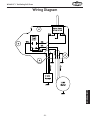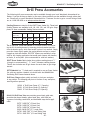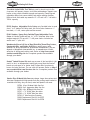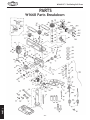
1
MODEL W1668 13 ⁄ 4" Oscillating Drill Press 1 OWNER'S MANUAL Phone: (360) 734-3482 • Online Technical Support: [email protected] COPYRIGHT ©2000 BY WOODSTOCK INTERNATIONAL, INC. REVISED APRIL, 2008 (BL) #4725CR WARNING: NO PORTION OF THIS MANUAL MAY BE REPRODUCED IN ANY SHAPE OR FORM WITHOUT THE WRITTEN APPROVAL OF WOODSTOCK INTERNATIONAL, INC. Printed in China K_`jdXelXcgifm`[\jZi`k`ZXcjX]\kp`ejkilZk`fejfek_\gifg\ij\klg# fg\iXk`fe#dX`ek\eXeZ\Xe[j\im`Z\f]k_`jdXZ_`e\&\hl`gd\ek% =X`cli\kfi\X[#le[\ijkXe[Xe[]fccfnk_\`ejkilZk`fej^`m\e`ek_`j dXelXcdXpi\jlck`ej\i`fljg\ijfeXc`ealip#`eZcl[`e^XdglkXk`fe# \c\ZkifZlk`fefi[\Xk_% K_\fne\if]k_`jdXZ_`e\&\hl`gd\ek`jjfc\cpi\jgfej`Yc\]fi`kjjX]\ lj\%K_`ji\jgfej`Y`c`kp`eZcl[\jYlk`jefkc`d`k\[kfgifg\i`ejkXccX$ k`fe`eXjX]\\em`ifed\ek#g\ijfee\ckiX`e`e^Xe[ljX^\Xlk_fi`qX$ k`fe#gifg\i`ejg\Zk`feXe[dX`ek\eXeZ\#dXelXcXmX`cXY`c`kpXe[ Zfdgi\_\ej`fe#Xggc`ZXk`fef]jX]\kp[\m`Z\j#YcX[\&Zlkk\i`ek\^i`kp# Xe[k_\ljX^\f]g\ijfeXcgifk\Zk`m\\hl`gd\ek% K_\dXel]XZkli\in`ccefkY\_\c[c`XYc\]fi`ealipfigifg\ikp [XdX^\]ifde\^c`^\eZ\#`dgifg\ikiX`e`e^#dXZ_`e\df[`]`ZXk`fejfi d`jlj\% Jfd\[ljkZi\Xk\[Ypgfn\ijXe[`e^#jXn`e^#^i`e[`e^#[i`cc`e^#Xe[ fk_\iZfejkilZk`feXZk`m`k`\jZfekX`ejZ_\d`ZXcjbefnekfk_\JkXk\f] :Xc`]fie`XkfZXlj\ZXeZ\i#Y`ik_[\]\Zkjfifk_\ii\gif[lZk`m\_Xid% Jfd\\oXdgc\jf]k_\j\Z_\d`ZXcjXi\1 C\X[]ifdc\X[$YXj\[gX`ekj% :ipjkXcc`e\j`c`ZX]ifdYi`Zbj#Z\d\ekXe[fk_\idXjfeipgif[lZkj% 8ij\e`ZXe[Z_ifd`ld]ifdZ_\d`ZXccp$ki\Xk\[cldY\i% Pflii`jb]ifdk_\j\\ogfjli\jmXi`\j#[\g\e[`e^fe_fnf]k\epfl [fk_`jkpg\f]nfib%Kfi\[lZ\pfli\ogfjli\kfk_\j\Z_\d`ZXcj1 Nfib`eXn\ccm\ek`cXk\[Xi\X#Xe[nfibn`k_Xggifm\[jX]\kp\hl`g$ d\ek#jlZ_Xjk_fj\[ljkdXjbjk_XkXi\jg\Z`Xccp[\j`^e\[kf]`ck\i flkd`ZifjZfg`ZgXik`Zc\j% SAFETY................................................4 Standard Safety Instructions.................... 4 Additional Safety for Drill Presses.............. 6 Avoiding Potential Injuries....................... 7 PARTS............................................... 32 W1668 Parts Breakdown ....................... 32 Parts List.......................................... 33 Warranty Registration.......................... 35 WARRANTY......................................... 37 ADJUSTMENTS OPERATIONS ADJUSTMENTS..................................... 15 Belt Tension...................................... 15 Feed Shaft Spring Tension..................... 16 Quill-Shaft Screw................................ 17 Table Height and Tilt........................... 18 Drilling Speed.................................... 19 Drill Press RPM Chart........................... 20 Drilling Depth.................................... 20 SET UP SETUP.................................................9 Unpacking.......................................... 9 Inventory........................................... 9 Base and Column................................ 10 Dust Port.......................................... 10 Table Support.................................... 11 Table.............................................. 12 Headstock........................................ 13 Drill Chuck....................................... 14 Handles........................................... 14 MAINTENANCE..................................... 27 General........................................... 27 Lubrication....................................... 27 Table and Base................................... 27 Sanding Sleeves.................................. 27 Troubleshooting.................................. 28 Wiring Diagram.................................. 29 Drill Press Accessories.......................... 30 ELECTRICAL ELECTRICAL..........................................8 110V Operation.................................... 8 Extension Cords................................... 8 Electrical Specifications......................... 8 OPERATIONS....................................... 23 Drill Press......................................... 23 Drill/Drum Changes............................. 24 Using the Oscillator............................. 25 SAFETY INTRODUCTION......................................2 Woodstock Technical Support................... 2 Specifications...................................... 3 INTRODUCTION CONTENTS MAINTENANCE PARTS USE THE QUICK GUIDE PAGE LABELS TO SEARCH OUT INFORMATION FAST! INTRODUCTION W1668 131⁄4" Oscillating Drill Press INTRODUCTION Woodstock Technical Support This machine has been specially designed to provide many years of trouble-free service. Close attention to detail, ruggedly built parts and a rigid quality control program assure safe and reliable operation. Woodstock International, Inc. is committed to customer satisfaction. Our intent with this manual is to include the basic information for safety, setup, operation, maintenance, and service of this product. We stand behind our machines! In the event that questions arise about your machine, please contact Woodstock International Technical Support at (360) 734-3482 or send e-mail to: tech-support@shopfox. biz. Our knowledgeable staff will help you troubleshoot problems and process warranty claims. If you need the latest edition of this manual, you can download it from http://www.shopfox.biz. If you have comments about this manual, please contact us at: Woodstock International, Inc. Attn: Technical Documentation Manager P.O. Box 2309 Bellingham, WA 98227 Email: [email protected] -2- Specifications Motor Type:.................................................. TEFC Capacitor Start Induction Motor:............................................3⁄4 HP, 110V, 9 Amp., Single Phase ⁄ 60 Hz RPM:........................................................................................... 1725 Power Transfer:..................................................................... V-Belt Drive Bearings:................................................ Shielded & Lubricated Ball Bearings Switch:......................................... Toggle ON/OFF Switch, W/ Safety Lock Tab Oscillating Stoke Length:.................................................................... 3⁄4" Spindle Travel:............................................................................... 3 1⁄4'' Maximum Distance, Spindle to Base:...................................................... 24'' Maximum Distance, Spindle to Table:.................................................. 17 1⁄4'' Overall Height:................................................................................ 38'' Dust Port Size:............................................................................... 2 1⁄4'' Spindle Taper:...............................................................................JT-33 Table Swing:................................................................................ 13 1⁄4'' Table Tilt:...................................................................................... 90° Chuck Size:........................................................ 5⁄8'' (1-16mm JT-33), Keyed Speeds:....................................................................... 12, Belt Controlled Range of Speeds:......... 250, 330, 380, 500, 590, 640, 980, 1530, 1600, 1870, 2580, 3050 RPM Drilling Capacity:........................................................ 3⁄4'' Diameter in Steel Approximate Shipping Weight:.........................................................130 lbs. -3- INTRODUCTION W1668 131⁄4" Oscillating Drill Press W1668 131⁄4" Oscillating Drill Press SAFETY J8=<KP I<8;D8EL8C9<=FI<FG<I8K@E>D8:?@E<% =8@CLI<KF=FCCFN@EJKIL:K@FEJ9<CFNN@CC I<JLCK@EG<IJFE8C@EALIP% @e[`ZXk\jXe`dd`e\ekcp_XqXi[fljj`klXk`fen_`Z_#`]efkXmf`[\[#N@CC i\jlck`e[\Xk_fij\i`flj`ealip% @e[`ZXk\jXgfk\ek`Xccp_XqXi[fljj`klXk`fen_`Z_#`]efkXmf`[\[#:FLC; i\jlck`e[\Xk_fij\i`flj`ealip% @e[`ZXk\jXgfk\ek`Xccp_XqXi[fljj`klXk`fen_`Z_#`]efkXmf`[\[#D8P i\jlck`ed`efifidf[\iXk\`ealip% EFK@:< K_`jjpdYfc`jlj\[kfXc\ikk_\lj\ikflj\]lc`e]fidXk`feXYflkgifg\i fg\iXk`fef]k_\\hl`gd\ek#Xe[&fiXj`klXk`fek_XkdXpZXlj\[XdX^\ kfk_\dXZ_`e\ip% JkXe[Xi[JX]\kp@ejkilZk`fej (% I<8;K?IFL>?K?<<EK@I<D8EL8C9<=FI<JK8IK@E>D8:?@E<IP%DXZ_`e\ipgi\j\ekjj\i`flj `ealip_XqXi[jkflekiX`e\[lj\ij% )% 8CN8PJ LJ< 8EJ@ 8GGIFM<; J8=<KP >C8JJ<J N?<E FG<I8K@E> D8:?@E<IP% <m\ip[Xp \p\$ ^cXjj\jfecp_Xm\`dgXZki\j`jkXekc\ej\jÇk_\pXi\EFKjX]\kp^cXjj\j% *% 8CN8PJN<8I8E@FJ?8GGIFM<;I<JG@I8KFIN?<EFG<I8K@E>D8:?@E<IPK?8KGIF;L:<J ;LJK%Nff[[ljk`jXZXiZ`ef^\eXe[ZXeZXlj\ZXeZ\iXe[j\m\i\i\jg`iXkfip`cce\jj\j% +% 8CN8PJ LJ< ?<8I@E> GIFK<:K@FE N?<E FG<I8K@E> D8:?@E<IP% DXZ_`e\ip ef`j\ ZXe ZXlj\ g\idXe\ek_\Xi`e^[XdX^\% ,% N<8IGIFG<I8GG8I<C%;FEFKn\Xicffj\Zcfk_`e^#^cfm\j#e\Zbk`\j#i`e^j#fia\n\cipn_`Z_dXp ^\k ZXl^_k `e dfm`e^ gXikj% N\Xi gifk\Zk`m\ _X`i Zfm\i`e^ kf ZfekX`e cfe^ _X`i Xe[ n\Xi efe$jc`g ]ffkn\Xi% -% E<M<IFG<I8K<D8:?@E<IPN?<EK@I<;#FILE;<IK?<@E=CL<E:<F=;IL>JFI8C:F?FC% 9\d\ekXccpXc\ikXkXcck`d\jn_\eilee`e^dXZ_`e\ip% .% FECP8CCFNKI8@E<;8E;GIFG<ICPJLG<IM@J<;G<IJFEE<CKFFG<I8K<D8:?@E<IP%DXb\ jli\fg\iXk`fe`ejkilZk`fejXi\jX]\Xe[Zc\Xicple[\ijkff[% /% B<<G:?@C;I<E8E;M@J@KFIJ8N8P%B\\gXccZ_`c[i\eXe[m`j`kfijXjX]\[`jkXeZ\]ifdk_\nfib Xi\X% 0% D8B<NFIBJ?FG:?@C;GIFF=%Lj\gX[cfZbj#dXjk\ijn`kZ_\j#Xe[i\dfm\jkXikjn`kZ_b\pj% -4- W1668 131⁄4" Oscillating Drill Press ('% E<M<IC<8M<N?<ED8:?@E<@JILEE@E>%Kliegfn\iF==Xe[XccfnXccdfm`e^gXikjkfZfd\kf XZfdgc\k\jkfgY\]fi\c\Xm`e^dXZ_`e\leXkk\e[\[% ((% ;FEFKLJ<@E;8E><IFLJ<EM@IFED<EKJ%;FEFKlj\dXZ_`e\ip`e[Xdg#n\kcfZXk`fej#fi n_\i\Xep]cXddXYc\fiefo`flj]ld\jdXp\o`jk% (*% LJ<8>IFLE;<;<OK<EJ@FE:FI;I8K<;=FIK?<D8:?@E<8DG<I8><%Le[\ij`q\[Zfi[jfm\i$ _\XkXe[cfj\gfn\i%I\gcXZ\\ok\ej`feZfi[j`]k_\pY\Zfd\[XdX^\[%;FEFKlj\\ok\ej`feZfi[j ]fi))'MdXZ_`e\ip% (+% 8CN8PJ;@J:FEE<:K=IFDGFN<IJFLI:<9<=FI<J<IM@:@E>D8:?@E<IP%DXb\jli\jn`kZ_`j `eF==gfj`k`feY\]fi\i\Zfee\Zk`e^% (,% D8@EK8@ED8:?@E<IPN@K?:8I<%B\\gYcX[\jj_XigXe[Zc\Xe]fiY\jkXe[jX]\jkg\i]fidXeZ\% =fccfn`ejkilZk`fej]ficlYi`ZXk`e^Xe[Z_Xe^`e^XZZ\jjfi`\j% (-% D8B<JLI<>L8I;J8I<@EGC8:<8E;NFIB:FII<:KCP9<=FI<LJ@E>D8:?@E<IP% (.% I<DFM< 8;ALJK@E> B<PJ 8E; NI<E:?<J% DXb\ X _XY`k f] Z_\Zb`e^ ]fi b\pj Xe[ X[aljk`e^ ni\eZ_\jY\]fi\klie`e^dXZ_`e\ipFE% (/% :?<:B =FI ;8D8><; G8IKJ 9<=FI< LJ@E> D8:?@E<IP% :_\Zb ]fi Y`e[`e^ Xe[ Xc`^ed\ek f] gXikj#Yifb\egXikj#gXikdflek`e^#cffj\Yfckj#Xe[Xepfk_\iZfe[`k`fejk_XkdXpX]]\ZkdXZ_`e\ fg\iXk`fe%I\gX`ifii\gcXZ\[XdX^\[gXikj% (0% LJ<I<:FDD<E;<;8::<JJFI@<J%I\]\ikfk_\`ejkilZk`fedXelXc]fii\Zfdd\e[\[XZZ\jjfi`\j% K_\lj\f]`dgifg\iXZZ\jjfi`\jdXpZXlj\i`jbf]`ealip% )'%;FEFK=FI:<D8:?@E<IP%NfibXkk_\jg\\[]fin_`Z_k_\dXZ_`e\fiXZZ\jjfipnXj[\j`^e\[% )(% J<:LI< NFIBG@<:<% Lj\ ZcXdgj fi X m`j\ kf _fc[ k_\ nfibg`\Z\ n_\e giXZk`ZXc% 8 j\Zli\[ nfibg`\Z\gifk\Zkjpfli_Xe[jXe[]i\\jYfk__Xe[jkffg\iXk\k_\dXZ_`e\% ))% ;FEFKFM<II<8:?%B\\ggifg\i]ffk`e^Xe[YXcXeZ\XkXcck`d\j% )*% D8EPD8:?@E<JN@CC<A<:KK?<NFIBG@<:<KFN8I;K?<FG<I8KFI%BefnXe[Xmf`[Zfe[`$ k`fejk_XkZXlj\k_\nfibg`\Z\kfb`ZbYXZb% )+% 8CN8PJCF:BDF9@C<98J<J@=LJ<; 9<=FI<FG<I8K@E>D8:?@E<IP% ),% 9< 8N8I< K?8K :<IK8@E ;LJK D8P 9< ?8Q8I;FLJ kf k_\ i\jg`iXkfip jpjk\dj f] g\fgc\ Xe[ Xe`dXcj#\jg\Z`Xccp]`e\[ljk%DXb\jli\pflbefnk_\_XqXi[jXjjfZ`Xk\[n`k_k_\kpg\f][ljkpfl n`ccY\\ogfj\[kfXe[XcnXpjn\XiXi\jg`iXkfiXggifm\[]fik_Xkkpg\f][ljk% -5- SAFETY ()% B<<GNFIB8I<8:C<8E8E;N<CCC@K%:clkk\iXe[[Xibj_X[fnjdXpZXlj\XZZ`[\ekj% W1668 131⁄4" Oscillating Drill Press SAFETY Additional Safety for Drill Presses READ and understand this entire instruction manual before using this machine. Serious personal injury may occur if safety and operational information is not understood and followed. DO NOT risk your safety by not reading! Use this and other machinery with caution and respect. Always consider safety first, as it applies to your individual working conditions. No list of safety guidelines can be complete—every shop environment is different. Failure to follow guidelines could result in serious personal injury, damage to equipment or poor work results. 1. EYE/FACE/HAND PROTECTION. A face shield used with safety glasses is recommended. Always keep hands and fingers away from the drill bit. Never hold a workpiece by hand while drilling! DO NOT wear gloves when operating the drill. 2. SECURING BIT. Properly tighten and securely lock the drill bit in the chuck. 3. CORRECT BIT. Use only round, hex, or triangular shank drill bits. 4. ADJUSTING KEYS AND WRENCHES. Remove all adjusting keys and wrenches before turning the machine ON. 5. DRILLING SHEET METAL. Never drill sheet metal unless it is securely clamped to the table. 6. SURFACE/WORKPIECE PREP. Never turn the drill press ON before clearing the table of all objects (tools, scrap wood, etc.) DO NOT drill material that does not have a flat surface, unless a suitable support is used. 7. DAMAGED TOOLS. Never use drill bits in poor condition. Dull or damaged drill bits are hard to control and may cause serious injury. 8. DRILL OPERATION. Never start the drill press with the drill bit pressed against the workpiece. Feed the drill bit evenly into the workpiece. Back the bit out frequently to clear deep holes. 9. CLEARING CHIPS. Turn the machine OFF and clear chips and scrap pieces with a brush. Disconnect power, remove drill bit, and clean table before leaving the machine. 10. OPERATING SPEED. Always operate your drill press at speeds that are appropriate for the drill bit size and the material that you are drilling. 11. MOUNTING WORKPIECES. Use clamps or vises to secure workpiece before drilling. Position work so you avoid drilling into the table. 12. TABLE LOCK. Make sure the table lock is tightened before starting the drill press. 13. MAINTENANCE/SPEED CHANGES. Never change speeds or do maintenance with the machine connected to power. 14. EXPERIENCING DIFFICULTIES. If at any time you are experiencing difficulties performing the intended operation, stop using the machine! Contact our Technical Support at (360) 734-3482. -6- W1668 131⁄4" Oscillating Drill Press Avoiding Potential Injuries SAFETY Figure 3. Keep fingers away from spinning drill bits, cutters, and sanding surfaces. Figure 1. Never drill while holding the workpiece by hand. Figure 4. Remove handles when using the oscillating sanding feature. Figure 2. Remove switch safety key when not in use. -7- W1668 131⁄4" Oscillating Drill Press ELECTRICAL ELECTRICAL The machine must be properly set up before it is safe to operate. DO NOT connect this machine to the power source until instructed to do so in the "Test Run" portion of this manual. 110V Operation The Model W1668 is wired for 110V operation. We recommend connecting this machine to a dedicated circuit with a verified ground, using the circuit size below as a minium. Never replace a circuit breaker with one of higher amperage without consulting a qualified electrician to ensure compliance with wiring codes. Figure 5. 5-15 plug and receptacle. This machine must be grounded! The electrical cord supplied with this machine comes with a grounding pin. If your outlet does not accommodate a ground pin, have it replaced by a qualified electrician. If you are unsure about the wiring codes in your area or you plan to connect your machine to a shared circuit, you may create a fire or circuit overload hazard— consult a qualified electrician to reduce this risk. Extension Cords DO NOT work on your electrical system if you are unsure about electrical codes and wiring! Seek assistance from a qualified electrician. Ignoring this warning can cause electrocution, fire, or machine damage. We do not recommend using an extension cord; however, if you have no alternative, use the following guidelines: • • • • Use a cord rated for Standard Service (S). Do not use an extension cord longer than 50 feet. Ensure that the cord has a ground wire and pin. Use the gauge size listed below as a minimum. Electrical Specifications Operating Voltage Amp Draw Min. Circuit Size Plug/Recommended Plug Extension Cord 110V Operation 9 Amps 15A NEMA 5-15 14 Gauge -8- W1668 131⁄4" Oscillating Drill Press SETUP Unpacking This machine has been carefully packaged for safe transportation. If you notice the machine has been damaged during shipping, please contact your authorized Shop Fox dealer immediately. Inventory The following is a description of the main components shipped with the Model W1668. Lay the components out to inventory them. Keep machine disconnected from power until instructed otherwise. Note: If you can't find an item on this list, check the mounting location on the machine or examine the packaging materials carefully. Occasionally we pre-install certain components for safer shipping. Tools and Fasteners (not shown) Qty —Special Wrench 25mm...................................1 —Open End Wrench 13 x 14...............................1 —Hex Wrenches 3, 4, 5mm............................1ea —Hex Nut M8-1.25 (Mandrel).............................1 —Mandrel Washers 3⁄4" OD x 5⁄8" ID (Mandrel).........2 —Mandrel Washer 7⁄8" OD x 3⁄8" ID (Mandrel)..........1 —Mandrel Washer 5⁄8" OD x 3⁄8" ID (Mandrel)..........1 —Hex Bolt M10-1.5 x 25 (Colum/Base)..................4 —Phillips Head Screws M4-.7 x 22 (Dust Port).........4 —Cap Screw M5-.8 x 20 (Chuck).........................1 -9- C B SETUP Box Inventory (Figure 6 & 7) Qty A.. Headstock Assembly........................................1 B.. Table..........................................................1 C.. Column.......................................................1 D.. Rack..........................................................1 E.. Table Bracket...............................................1 F.. Rack Ring....................................................1 G.. Base...........................................................1 H.. Dust Port Halves............................................2 I.. Table Inserts (5⁄8", 1", 13⁄8", 17⁄8")....................1ea J.. Sanding Mandrel............................................1 K.. Spindle Handles.............................................3 L.Hand Crank Handle. .Hand ........................................1 Crank Handle M.. Hand Crank..................................................1 N.. Lock Handle M12-1.75.....................................1 O.. Lock Handle M10-1.5.......................................1 P.. Belt Cover Knob.............................................1 Q.. Key............................................................1 R.. Drill Chuck JT33............................................1 S.. Pinion Gear..................................................1 T.. Spindle Sander Set D2877 (not shown)..................1 A D E G F H Figure 6. W1668 inventory. J I K L M S N R Q P O Figure 7. Additional W1668 inventory items. W1668 131⁄4" Oscillating Drill Press Base and Column The base and column must be securely mounted, so the machine will not fall over. To install the base and column, do these steps: 1. Position the drill press base on a flat and stable surface. 2. Using two clamps, clamp the base to the mounting surface. 3. Use the holes provided in the bottom of the base as a drill guide, and drill holes in the mounting surface (see Figure 8). SETUP 4. Secure the base with 5⁄16" lag bolts or supplied through-bolts with washers and nuts. Figure 8. Using holes as a drill guide. 5. Place the column on the base, line up the four mounting holes, and secure tightly with the four M10-1.5 x 25 hex bolts, using a 16mm wrench. Dust Port The dust port directs suction to the sanding sleeve, removing hazardous dust and increasing abrasive life. To install the dust port, do these steps: 1. Bring the dust port halves together, align the mounting holes on the dust port and table, then secure with the four M4-.7 x 22 Philips head screws, as shown in Figure 9. Figure 9. Installing the dust port. -10- W1668 131⁄4" Oscillating Drill Press Table Support When secured to the column, the table support supports the table, provides smooth table height adjustment, and locks in position with firm lever torque. Additionally, when the table is rotated, the rack will slide with the table support. 12mm Lock Handle To install the table support, do these steps: 1. Insert the 12mm lock handle into the table support bracket through the blind hole, into the threaded hole, and thread inward three turns, as shown in Figure 10. 2. If the pinion is not already installed, insert it shaft-end into the hole on the side of the table support bracket, as shown in Figure 11. Figure 10. Loosely installing table lock lever. SETUP 3. Align the set screw in the crank handle with the flat on the pinion shaft and tighten, as shown in Figure 12. 4. Thread the handle into the crank handle (Figure 12). 5. If the column ring is installed on the colum, loosen the set screw on the ring and remove it. Flat on Pinion Figure 11. Pinion installation positioning. Crank Handle Handle Flat on Pinion Figure 12. Crank and set screw positioning. -11- W1668 131⁄4" Oscillating Drill Press 6. Position the rack so the long un-toothed end is facing upward (see Figure 13). Long Un-toothed Rack End is Facing Upward 7. Insert the rack into the table support bracket so the teeth face out and mesh with the pinion (see Figure 13). 8. While holding the rack in place, slide the table support bracket onto the column. 9. Allow the bracket and rack to slide down until the bottom of the rack bevel slips into the tapered shoulder on the column support. SETUP 10. Slide the column ring onto the column with the inside bevel in the down position (see Figure 14). Figure 13. Rack, column, table support position. 11. Adjust the ring until the tip of the rack fits inside the bevel, and the rack rotates freely when you rotate the table support around the column. 12. Secure the table support with the table lock lever. NOTICE Column Ring Bevel Facing Downward Use caution when tightening the set screw. Over tightening will split the column ring. Figure 14. Column ring bevel positioning. 13. Carefully tighten the set screw on the ring. Table When installed correctly, the table should lock in position with firm lever torque. To install the table, do these steps: 1. Thread the 10mm lock handle into the table bracket through the blind hole, into the threaded hole, and thread inward three turns. 10mm Lock Handle 2. Align the shaft under the table with the hole on the end of the table support bracket and install (see Figure 15). Figure 15. Table installation. 3. Tighten the table lock lever. -12- W1668 131⁄4" Oscillating Drill Press Headstock The headstock must be tightened in position with two set screws, so the headstock is aligned with the drill press foot for balance and weight distribution. DO NOT over tighten the set screws and strip the threads or bend the column. Belt Cover Knob GET assistance before beginning the next step. The headstock is an awkward and heavy load. To install the headstock, do these steps: Figure 16. Aligning the pocket in the headstock with the column. SETUP 1. With an assistant, position the pocket over the column (Figure 16) and allow the headstock to slide down until the column fully seats up and into the headstock (approximately 31⁄2"). Tip: Place a few drops of multi-purpose grease on the column to help the headstock seat more easily. 2. Align the headstock directly over the foot of the base as viewed from the front of the drill press and center it using a plumb bob and ruler (see Figure 17). 3. Tighten the two set screws to secure the headstock to the column (see Figure 18). Figure 17. Aligning headstock with base. 4. Install the belt cover knob with the included Phillips head screw (see Figure 16). Set Screws -13- Figure 18. Securing the headstock to the column. W1668 131⁄4" Oscillating Drill Press Drill Chuck The drill chuck is seated to the spindle with a JT-33 tapered surface and a screw. To install the drill chuck, do these steps: 1. Clean the drill chuck and spindle with mineral spirits and follow all safety warnings on the container. Failure to clean the tapered-mating surfaces of the spindle and drill chuck will result in the chuck falling off during use. 2. Use the provided chuck key to adjust the jaws of the chuck until they are well inside the drill chuck body (see Figure 19). Figure 19. Jaws adjusted inside chuck body. SETUP NOTICE DO NOT use a hammer to seat the drill chuck onto the spindle. You will damage the oscillating mechanism. 3. Place the drill chuck on the spindle, and insert the capscrew into the hole of the drill chuck, as shown in Figure 20. 4. Tighten the screw so the drill chuck is seated securely on the spindle. • If the chuck fails to remain secure on the spindle, repeat Step 1, DO NOT use a hammer to seat the drill chuck onto the spindle! Figure 20. Inserting the hex cap screw. Handles Three handles are supplied for drilling operations. NOTE: Remove these handles when you use the oscillating feature. To install the handles, do these steps: 1. Thread the handles into the hub, as shown in Figure 21. 2. Tighten the handles with the included wrench until they are snug, DO NOT overtighten. Figure 21. Installing spindle handles. -14- W1668 131⁄4" Oscillating Drill Press ADJUSTMENTS Belt Tension Motor Lock Screw The drill press main drive belts last a long time; however, during machine life, a belt may stretch slightly which can cause the pulleys to slip under a load. You will then need to adjust the motor-to-idler pulley belt tension to compensate for this normal stretching. NOTE: The spindle-to-idler pulley belt automatically adjusts to the correct tension when the motor-to-idler pulley belt tension is adjusted. Push Rod NOTICE Figure 22. Motor lock screw. The oscillator belt is not adjustable. If the belt shows cracks or is slipping, replace the belt with a new one. Motor Pulley To adjust the drive belt tension, do these steps: Belt Deflection gap should be about 11⁄2" 1. UNPLUG THE DRILL PRESS! Figure 23. Measuring belt deflection. 2. Open the belt cover. 3. Loosen the motor lock screw at the side of the headstock, as shown in Figure 22. 4. Gently pivot the motor away from the push rod rubber until the belt is tight. 5. Hold the motor in position so the rubber pad is held against the motor. 6. Tighten the lock screw, and make sure the belt deflection gap is correct when pinched together between the pulleys (see Figure 23). • If the gap between both inner sides of the belt is greater or less than 11⁄2", repeat Steps 3 through 6 until the deflection gap is 11⁄2". -15- ADJUSTMENTS MAKE SURE your machine is unplugged during all assembly, adjustments, or maintenance procedures. Otherwise serious personal injury may occur! W1668 131⁄4" Oscillating Drill Press Feed Shaft Spring Tension The feed shaft return spring is adjusted at the factory; however, during the life of the drill press you may want to adjust the feed shaft return spring to a stronger return pressure. Cover Nut MAKE SURE your machine is unplugged during all assembly, adjustments, or maintenance procedures. Otherwise serious personal injury may occur! Jam Nut Spring Lock Cover Figure 24. Typical feed shaft return spring assy. Depth Stop Reads “0” ADJUSTMENTS WEAR safety glasses when adjusting springs. Serious injury may occur if this warning is ignored! To adjust the feed shaft spring tension, do these steps: Rotate Oscillator Pulley Until Depth Stop Reads Zero. 1. UNPLUG THE DRILL PRESS! 2. Wipe off any oil on the spring lock cover so it will not slip in your fingers when you hold the cover from spinning (see Figure 24). Figure 25. Fully seating quill shaft. 3. Rotate the oscillator pulley so the depth stop reads “0” and the quill shaft is completely seated, as shown in Figure 25. Locking Lug 4. Put on thick leather gloves and hold the spring cover against the side of the headstock, so the cover stays splined with the locking lug, and remove the jam nut to loosen the cover nut approximately 1⁄4" (6.4mm). 5. Pull the cover outward just enough to disengage the spring-cover lock slot from the locking lug (see Figure 26). Spring-Cover Lock Slot 6. Rotate the cover counterclockwise to increase spring tension, or let the cover slowly unwind in the clockwise direction to reduce spring tension (see Figure 26). Figure 26. Typical spring cover lock slot and locking lug. -16- W1668 131⁄4" Oscillating Drill Press 7. Engage the next available spring-cover lock slot with the locking lug, and hold the spring lock cover tightly against the side of the headstock (see Figure 27). Cover Nut 8. Snug the cover nut against the spring cover just until the nut stops, and then back-off the nut approximately 1⁄3 turn, or just enough so there is no binding anywhere along complete spindle travel. 9. Hold the cover nut and tighten the jam nut against the cover nut (see Figure 27). Quill-Shaft Screw While you may never have to adjust the quill shaft screw, you should understand its function and know how to adjust it should you ever need to remove the quill for cleaning. This screw prevents the quill from rotating during drilling and sanding procedures, and if adjusted incorrectly, the quill may have lash or bind. Figure 27. Hold the spring cover tightly. To adjust the quill-shaft screw, do these steps: Figure 28. Clean and oil quill shaft. 1. Unplug the drill press! 2. Clean and lubricate the quill shaft with a thin coat of light oil, and make sure the quill travels freely (see Figure 28). 3. Loosen the jam nut shown in Figure 29. 4. Turn the quil shaft screw clockwise or counterclockwise to establish free, unbinding travel while moving the quill up and down through its entire range of travel. 5. When the quil shaft screw is screwed inward against the quill as far as the screw can go without binding the quill, hold the screw and tighten the jam nut. 6. Recheck for quill binding and looseness while moving the quill up and down through its entire range of travel and readjust as required. -17- Jam Nut Quil Shaft Screw Figure 29. Typical quill-shaft screw and jam nut. ADJUSTMENTS UNPLUG your machine during all assembly, adjustments, and maintenance procedures. Otherwise serious personal injury may occur! W1668 131⁄4" Oscillating Drill Press Table Height and Tilt You can adjust the table height and tilt to accommodate for workpiece height or achieve special drilling/sanding angles. You can also move the table out of the way and use the drill press base as a table for drilling/sanding. To adjust the table, do these steps: 1. Loosen the table lock lever. 2. Turn the hand crank to raise or lower the table, as shown in Figure 30. 3. Position the table so the opening in the installed table insert is centered to the drill bit or sanding drum. • Figure 30. Raise or lower the table. If the table is not needed, pivot the table to the back side of the column (Figure 31) so you can support the workpiece on the base (drilling operations only). ADJUSTMENTS 4. Tighten the table lock lever. 5. Loosen the table tilt lock bolt. 6. Turn the index pin jam nut clockwise and draw the index pin out of the casting until you can rotate the table to your desired angle, and use the tilt scale to find your desired drilling or sanding angle (see Figure 32). NOTE: Use this index pin only for indexing the table in the “Zero degree” position. (To index the table back to the zero position, turn the table to zero, tap the index pin back into the casting, snug the index pin jam nut, and tighten the table tilt lock bolt.) Figure 31. Table adjusted behind column. Table Tilt Lock Bolt Index Pin and Index Pin Jam Nut 7. Tighten the tilt table lock bolt, and double check your angle. Tilt Scale Figure 32. Table tilt lock bolt. -18- W1668 131⁄4" Oscillating Drill Press Drilling Speed The Model W1668 13 1⁄4'' Oscillating Drill Press has 12 speeds ranging from 250 to 3050 RPM. Refer to the speed charts located under the belt guard while following the instructions below. Motor Lock Screw UNPLUG the drill press before changing speeds to avoid accidental start up. Failure to do this may result in serious personal injury. Push Rod To change the drilling speed, do these steps: Figure 33. Loosening the lock knob. 1. UNPLUG THE DRILL PRESS! 2. Refer to the speed chart located under the belt cover or refer to the “Drill Press RPM Chart” on Page 20, and choose the desired speed. ADJUSTMENTS 3. Loosen the motor lock screw (see Figure 33). 4. Pull the motor toward the front of the drill press to remove tension from the V-belt. 5. Move the V-belt to the desired V-grooves on the motor and spindle pulleys (see Figure 34). Figure 34. Adjusting belt to desired speed. 6. Push the motor toward the back of the headstock; the push rod is spring loaded and will follow the motor (see Figure 33). Motor Pulley 7. Tighten the lock screw, and make sure the belt deflection is 11⁄2" between both inner sides when the belt is pinched together between the pulleys, as shown in Figure 35. Refer to “Belt Tension” in the ADJUSTMENTS section on Page 15 for details. 8. Close the cover. The motor will not start until the cover is closed. Belt Deflection gap should be about 11⁄2" Figure 35. Measuring belt deflection. -19- W1668 131⁄4" Oscillating Drill Press Drill Press RPM Chart Use Figure 35 to select the optimum motor-to-spindle pulley ratio for drilling, cutting, and sanding operations. The belt setting in the example in Figure 36 shows the spindle belt in the #1 spindle pulley position and the motor belt in the #7 motor pulley location. This will produce a speed of 1,870 RPM. Refer to the Drill, Cutter, and Saw RPM Chart on Page 21 for suggested tool RPMs. Figure 36. Drill Press RPM Chart. Drilling Depth ADJUSTMENTS Your new drill press comes fitted with a depth stop that allows drilling holes at a preset depth. Depth Stop Reads “0” NOTICE BACK-OFF the depth stop completely and secure the stop nuts before using the oscillating feature. If the depth stop is left adjusted for a shallow hole, or the nuts rattle down to the stop while in operation, the depth stop will bottom out and break the oscillator. Rotate Oscillator Pulley Until Depth Stop Reads Zero. To adjust the drilling depth, do these steps: 1. UNPLUG THE DRILL PRESS! 2. Rotate the oscillator pulley until the depth stop reads “0” (see Figure 37). Figure 37. Retracting the oscillator for drilling. 3. Loosen the jam nut on the depth stop rod (see Figure 38). Jam Nut 4. Turn the stop nut to the desired depth as indicated by the depth stop scale (see Figure 38). 5. Tighten the jam nut against the stop nut while making sure the stop nut stays in position. Stop Nut 6. To make sure the depth has been set correctly, drill a hole into scrap stock before drilling into any workpiece, and readjust the depth stop if necessary. Figure 38. Actual stop depth being measured. -20- W1668 131⁄4" Oscillating Drill Press ADJUSTMENTS -21- ADJUSTMENTS W1668 131⁄4" Oscillating Drill Press -22- W1668 131⁄4" Oscillating Drill Press OPERATIONS Starting the Drill Press Once assembly is complete and adjustments are done to your satisfaction, you are ready to start the drill press. Every time you start the drill press, you should follow these basic instructions. Keep your shop “Child Safe.” Always remove the switch safety key when drill press is not in use. Serious injury may occur. WEAR safety glasses and a respirator during drilling or sanding operations. Otherwise serious personal injury may occur! To start the drill press, do these steps: 1. Make sure the starting switch paddle is down for OFF. 2. Make sure all fasteners and lock handles are tight. 3. Make sure the drill chuck key is removed. Figure 39. Hand poised over a typical stop switch. 4. Plug in the power cord. OPERATIONS 5. Lift the ON/OFF switch to start the drill press, and make sure that your finger is poised over the paddle, as shown in Figure 39, just in case there is a problem. 6. Listen and observe the drill press, it should run smoothly, with little or no vibration or rubbing noises. • If you hear strange or unusual noises, shut the drill press OFF, and wait for the spindle to stop moving. 7. Unplug the drill press and refer to the “Troubleshooting” table on Page 28 to help isolate and correct the problem before using the drill press again. -23- W1668 131⁄4" Oscillating Drill Press Drill/Drum Changes NEVER troubleshoot or adjust the machine while it is running. Wait until the machine is turned off, unplugged and all working parts have come to a stop before proceeding! To change drill bits and sanding drums, do these steps: 1. UNPLUG THE DRILL PRESS! 2. Use the chuck key to open the chuck wide enough to accept the new bit or the sanding drum mandrel (see Figure 40). Figure 40. Installing bit. 3. Install the bit or mandrel so the chuck jaws will grab as much of the bit or mandrel shank as it can. • If you are installing a small drill bit, make sure it is held between three jaws instead of only two, and NEVER allow a chuck to grab the fluted body of drill bits. OPERATIONS • If you are installing the sanding drum, install the paper and drum before installing the spindle into the drill chuck (contact your local SHOP FOX® dealer for drums and paper). Figure 41. Chuck key engaged. 4. Tighten the chuck with the chuck key, using any of the three key end locations. (see Figure 41). 5. Choose the insert that has an opening which is approximately 1⁄4" bigger than the sanding drum chosen. For drilling, always use the table insert (see Figure 42) with the smallest opening. A table insert is not needed when a 2" drum is used. 6. Install the chosen table insert into the pocket in the top of the table. 7. Remove the chuck key and reconnect the power source. 8. Reverse these steps to remove the drill bit or sanding drum. Figure 42. Sanding drum table insert. -24- W1668 131⁄4" Oscillating Drill Press Using the Oscillator One of the great features of the Model W1668 13 1⁄4'' Oscillating Drill Press is its sanding capability. The drill press can be converted from drilling operations to sanding operations in just a few steps. UNPLUG the machine and remove all handles before using the oscillating feature. The handles swing during operation. Belt and storage bracket To use the oscillating feature, do these steps: Figure 43. Oscillator belt on storage bracket. 1. UNPLUG THE DRILL PRESS! 2. Remove the spindle handles. 3. Lift the belt cover and remove the round belt located on the storage bracket under the speed chart, as shown in Figure 43. 4. Stretch the belt onto the top groove in the spindle and oscillating pulley, as shown in Figure 44. Figure 44. Stretch the belt to fit on pulleys. 5. Close the cover. The motor will not start until the cover is closed. OPERATIONS 6. Loosen the jam nut for the depth stop and adjust both nuts until they are positioned at the top of the depth stop rod. Tighten the jam nut (see Figure 45). NOTICE ALWAYS back-off the depth stop completely and secure the depth stop nuts before using the oscillating feature. If the depth stop is left adjusted for a shallow hole, or the nuts rattle down to the stop while in operation, the depth stop will bottom out and break the oscillator. Figure 45. Back-off the depth stop nuts. -25- W1668 131⁄4" Oscillating Drill Press 7. Remove the mandrel nut from the mandrel. 8. Install the sanding drum, sandpaper, and top and bottom mandrel washers on the mandrel, then secure with the mandrel nut, as shown in Figure 46. Insert Bottom Mandrel Washer 9. Choose the insert that has an opening which is slightly bigger than the sanding drum chosen (see Figure 46). • For general drill bits, small reamers, and miscellaneous small cutting and sanding bits, use the 5⁄8'' and the 1'' table inserts. Mandrel Nut • For the 1'' sanding drum, use the 1 3⁄8'' table insert. Figure 46. Sanding drum table insert. • For the 1 1⁄2'' sanding drum, use the 1 7⁄8'' table insert. Top Mandrel Washer • For the 2'' sanding drum, use no table insert. 10. Set the chosen table insert into the pocket in the top of the table, insert the sanding drum mandrel into the chuck, then tighten chuck (see Figure 47). Insert 11. Loosen and pivot the table so the opening in the installed table insert is centered to the drill bit or sanding drum. OPERATIONS Figure 47. Sanding drum installed. NEVER sand or drill without the table in position and the workpiece secured. Serious personal injury may occur. 12.Adjust the table height to use all of the grit on the paper as the paper wears. • If the thickness of the workpiece does not allow much table movement and the sanding drum paper is partially worn on one end, remove the drum from the sanding spindle, turn it end for end and replace it on the sanding spindle to use the newer part of the sandpaper. 13.Turn the drill press ON, and begin sanding. -26- W1668 131⁄4" Oscillating Drill Press MAINTENANCE Table and Base General Keep the table and other unpainted surfaces rust-free with regular applications of products like Boeshield® T-9. For long term storage consider products like Kleen Bore's Rust Guardit™. Periodic maintenance on your Model W1668 131⁄4'' Oscillating Drill Press will ensure its optimum performance. Make a habit of inspecting your drill press after each use. Sanding Sleeves NEVER adjust or service the machine while it is running. Wait until the machine is turned off, unplugged and all working parts have come to a stop before proceeding! As sanding drums are used, the abrasive sleeve will quickly become "loaded" with sawdust. If not removed, this sawdust will harden on the abrasive surface, rendering the sleeve useless. Routinely clean the sanding sleeve with a rubber gum abrasive cleaner like the PRO-STIK® cleaners, as shown on Page 30. Check for the following conditions and repair or replace when necessary. 1. Loose mounting bolts. Always discard worn sanding sleeves. As abrasive sleeves begin to wear, grit will begin to fall off and cause gouges in the workpiece. Glue used to hold the grit to the paper will rub off onto the workpiece interfering with the final finish. 2. Worn switch. 3. Worn or damaged cords and plugs. 4. Damaged drive belts. 5. Any other condition that could hamper the safe operation of this machine. Lubrication Since all bearings are shielded and permanently lubricated, simply leave them alone until they need to be replaced. DO NOT lubricate them. NOTICE Your goal is to achieve adequate lubrication. Too much lubrication will attract dirt and sawdust. Various parts of your machine could loose their freedom of movement as a result. -27- MAINTENANCE Contrary to some beliefs, worn abrasives are not the equivalent the next finer grit abrasive. Discard worn sanding sleeves and avoid the temptation to use them beyond their usable life. For other items on this machine, such as the quill, table and column, an occasional application of light machine oil is all that is necessary. Before applying lubricant, clean off sawdust and metal chips. W1668 131⁄4" Oscillating Drill Press Troubleshooting MAINTENANCE Use this table to isolate and correct any problems with your drill press. If you cannot correct a problem, contact Woodstock International, Inc. at 1-360-734-3482 or [email protected]. Page 17 -28- W1668 131⁄4" Oscillating Drill Press Wiring Diagram MAINTENANCE -29- W1668 131⁄4" Oscillating Drill Press Drill Press Accessories The following drill press accessories may be available through your local Woodstock International Inc. Dealer. If you do not have a dealer in your area, these products are also available through online dealers. Please call or e-mail Woodstock International Inc. Customer Service to get a current listing of dealers at: 1-800-545-8420 or at [email protected]. Sanding Sleeves are sized to fit the D2677 Drum Sander Set. These hard Sanding Sleeves are available in 60, 80, 100, 120, and 150 grits. Keep plenty of these consumable Sanding Sleeves on hand. Sanding Sleeves Size (Dia. x Ht.) 1" X 1⁄4" 1 ⁄2" X ⁄4" 1 1 2" X 41⁄4" 60 Grit 80 Grit 100 Grit 120 Grit 150 Grit D2683 D2685 D2687 D2684 D2686 D2688 D2689 D2690 D2691 D2692 D2693 D2694 D2695 D2696 D2697 The 4" PRO-STIK® Stick with Handle is the easiest solution for increasing the life of sanding sleeves by removing pitch and sawdust particles from the abrasive pores, which later harden in place if not removed. Simply press the cleaner lightly against the moving abrasive surface to remove clogged-up pitch and sawdust. PRO-STIK® cleaners are available in other sizes for any cleaning application that would need cleaners with handles, as blocks, or as flat pads. (Not recommended for wide-belt sanders.) D2677 Drum Sander Set includes three rubber sanding drums 41⁄4" in length to accommodate 1", 11⁄2" and 2" diameter sanding sleeves. This kit also includes one 80 grit sleeve for each drum to get things started. MAINTENANCE D2722 Mandrel is a 3⁄8" shank and is required to use our Drum Sander Set with any machine. Mandrel is included with the SHOP FOX® Oscillating Drill Presses featured above. Drill Press Clamps adjust quickly and easily to lock your workpiece in any position. The clamping pad pivots to conform to any workpiece, ensuring uniform pressure. W1301 6" Drill Press Clamp (11⁄2" Capacity) D2192 10" Drill Press Clamp (3" Capacity) D2493 12" Drill Press Clamp (5" Capacity) SHOP FOX Drill Press Vises use precision ground steel guide rods, smooth-action Acme threads, ground steel jaws, with fixed jaw V-grooves for holding round stock, and dovetailed ways where applicable. D2727 SHOP FOX® (3" Basic Vise) D2728 SHOP FOX® (4" Basic Vise) D2729 SHOP FOX® (6" Basic Vise) D2933 SHOP FOX® (33⁄4" Angle Vise) D2730 SHOP FOX® (3" Cross Sliding Vise) D2731 SHOP FOX® (4" Cross Sliding Vise) -30- W1668 131⁄4" Oscillating Drill Press The SHOP FOX® D2056 Tool Table is great for bench-top tools like chop saws, drill presses, planers, scroll saws and bandsaws. Support cross braces on top provide incredible strength and capacity. Flared legs and adjustable rubber feet ensure stability and reduce machine vibration. Butcher block finish table top measures 13" x 23" and is 301⁄2" tall with a 700 lb. capacity. D2251 Steelex® Adjustable Circle Cutter cuts flat-sided holes in wood from 1" to 5". Made of M-2 alloy steel, this Circle Cutter features a 3⁄8" hex shank, 5⁄16" drill, center point and hex wrench. D3161 Steelex® Heavy-Duty Carbide-Tipped Adjustable Circle Cutter is Carbide Tipped and cuts 13⁄4" to 53⁄4" diameter holes in the toughest material. For use with 1⁄2" drill press chucks. Includes hex wrench and 7⁄16" pilot drill. Woodstock offers a full line of Brad Point Bits,Tenon/Plug Cutters, Countersink Bits, and Stubby Drill Bits to satisfy every need. Whether for do-it-yourselfers or professional woodworkers, you can depend on Woodstock International Inc. to manufacture a useful selection of drilling and cutting tools. Refer to http://www.woodstockint.com/drilling.cfm for a complete product line available through your dealer. Steelex® Carded Forstner Bits stack up as some of the best bits in the world. In fact, an independent testing lab proved that the Steelex® brand cut was equal to or better than Forstner Bits from Austria, known for being the best. For use with drill presses. Refer to http:// www.woodstockint.com/forstner.cfm for a complete product line available through your dealer. Steelex Plus® Bi-Metal Hole Saws stay sharper longer than carbon steel hole saws. Equipped with high-speed steel alloy cutting teeth bonded to a welded steel body, they cut wood, metal and plastics with ease. D2784 D2020 D2783 D2797 D2798 D2799 D2928 D2929 10-pc. Bi-Metal Hole Saw Set 8-pc. Aggressive Hole Saw Set 6-pc. Bi-Metal Hole Saw Set 1 ⁄2" X 20 UNF Hole Saw Arbor 5 ⁄8" X 18 UNF Hole Saw Arbor 12" Hole-Saw Arbor Extension Replacement Pilot Drill for D2797 Replacement Pilot Drill for D2798 -31- MAINTENANCE W1668 131⁄4" Oscillating Drill Press PARTS W1668 Parts Breakdown PARTS 7A -32- W1668 131⁄4" Oscillating Drill Press Parts List DESCRIPTION REF PART # DESCRIPTION BASE COLUMN COLUMN & COLUMN FLANGE ASSEMBLY HEX BOLT M10-1.5 X 25 RACK V2.06.06 COLUMN RING SET SCREW M6-1.0 X 10 TABLE V2.05.03 WORM PINION CLAMP BOLT M12-1.75 X 50 WORM GEAR LIFT HANDLE SET SCREW M6-1.0 X 10 CLAMP BOLT M10-1.5 X 30 DUST PORT PHLP HD SCR M4-.7 X 22 HEAD CASTING HEX NUT M10-1.5 SPRING COVER RETURN SPRING SPRING WASHER BUSHING HEX NUT M10-1.5 SPECIAL SET SCREW FEED SHAFT DEPTH COLLAR V1.08.00 DEPTH STOP ROD V2.04.02 ROLL PIN 6 X 20MM FEED COLLAR HANDLE BAR KNOB LOCK KNOB RIVET SET SCREW M8-1.25 X 10 SET SCREW M10-1.5 X 12 PHLP HD SCR M4-.7 X 10 EXT TOOTH WASHER 4MM ROLL PIN 6 X 20MM PHLP HD SCR M4-.7 X 10 SWITCH BOX LIMIT SWITCH STRAIN RELIEF SHOP FOX PADDLE SWITCH PADDLE SWITCH KEY POWER CORD MOTOR 3/4 HP MOTOR FAN S. CAPACITOR 125V/200M MOTOR FAN COVER WIRING HARNESS CAPACITOR COVER CENTRIFUGAL SWITCH CONTACT PLATE HEX NUT M8-1.25 FLAT WASHER 8MM HEX BOLT M8-1.25 X 25 HEX BOLT M8-1.25 X 20 57 58 59 60 60-1 60-2 60-3 60-4 60-5 60-6 60-7 60-8 60-9 61 62 63 64 65 66 67 68 69 70 71 72 73 74 75 76 77 78 79 80 81 82 83 84 85 86 86A 87 88 88A 89 89A 90 91 92 93 94 95 96 97 98 99 100 102 PUSH ROD SPRING RUBBER WASHER OSCILLATING MECHANISM PLASTIC GEAR OSCILLATING MECHANISM ARM PULLEY WORM GEAR DRIVE ARM BODY SPECIAL BOLT FOR OSC. MECH ARM M6 X 20 LOWER SHOULDER CAP SCREW CAP SCREW M5-.8 X 15 OSCILLATOR BELT PULLEY COVER BALL BEARING 6203 COLLAR INTERNAL SPLINE SLEEVE SPLINE SLEEVE ASSY (63-65) MOTOR MOUNT LOCK NUT SPINDLE PULLEY PHLP HD SCR M6-1.0 X 20 LOCK WASHER 6MM PHLP HD SCR M5-0.8 X 10 FLAT WASHER 5MM KNOB MOTOR PULLEY KEY IDLER ARM IDLER PULLEY BALL BEARING 6202 INT RETAINING RING 35MM V-BELT M-20 3L200 (QTY 1) V-BELT M-26 3L260 (QTY 1) EXT RETAINING RING 11MM BALL BEARING 6201 RUBBER WASHER QUILL V1.08.00 QUILL ASSY (83-88) V3.06.01 BALL BEARING 6202ZZ SPINDLE V1.08.00 SPINDLE FOR JT33 CHUCK V2.01.05 DRILL CHUCK V1.08.00 CHUCK 3-16 MM JT33 V2.06.02 CHUCK KEY CAP SCREW M5-0.8 X 20 HEX NUT M8-1.25 MANDREL MANDREL WASHER - 1 3/4" MANDREL WASHER - 7/8" MANDREL WASHER - 5/8" WRENCH 14MM X 1/2" 3MM HEX WRENCH 4MM HEX WRENCH 5MM HEX WRENCH TABLE INSERT 5/8" I.D. X1668001 X1668003 X1668003-1 XPB32M X1668007A X1668008 XPSS01M X1668011A X1668012 X1668013 X1668015 X1668016 XPSS01M X1668019 X1668020 XPS36M X1668022 XPN02M X1668024 X1668025 X1668026 X1668027 XPN02M X1668029 X1668030 X1668031 X1668031A XPRP07M X1668033 X1668034 X1668035 X1668036 X1668038 XPSS16M XPSS13M XPS32M X1668042 XPRP07M XPS32M X1668045 X1668046 X1668047 XPSW09 XPSW09-1 X1668051 X1668052 X1668052-1 XPC200S X1668052-3 X1668052-4 X1668052-6 X1668052B X1668052C XPN03M XPW01M XPB07M XPB09M -33- X1668057 X1668058 X1668059 X1668060 X1668060-1 X1668060-2 X1668060-3 X1668060-4 X1668060-5 X1668060-6 X1668060-7 X1668060-8 XPSB10M X1668061 X1668062 XP6203 X1668064 X1668065 X1668066 X1668067 X1668068 X1668069 XPS31M XPLW03M XPS09M XPW02M X1668074 X1668075 X1668076 X1668077 X1668078 XP6202 XPR21M XPVM20 XPVM26 XPR48M XP6201 X1668085 X1668086 X1668086A XP6202 X1668088 X1668088A X1668089 X1668089A X1668090 XPSB15M XPN03M X1668093 X1668094 X1668095 X1668096 X1668097 XPW03M XPW04M XPW05M X1668102 PARTS REF PART # 1 3 5 6 7A 8 9 11A 12 13 15 16 17 19 20 21 22 23 24 25 26 27 28 29 30 31 31A 32 33 34 35 36 38 39 40 41 42 43 44 45 46 47 49 50 51 52 52-1 52-2 52-3 52-4 52-6 52-7 52-8 53 54 55 56 W1668 131⁄4" Oscillating Drill Press REF PART # DESCRIPTION REF PART # DESCRIPTION 103 104 105 106 107 108 114 115 116 117 118 135 139 140 TABLE INSERT 1" I.D. TABLE INSERT 1 3/8" I.D. TABLE INSERT 1 7/8" I.D. LONG HAIR SAFETY LABEL GLASSES SAFETY LABEL SHOP FOX LABEL DEPTH STOP BRACKET FLAT WASHER 5MM CAP SCREW M5-0.8 X 12 DEPTH STOP MOUNT CAP SCREW M8-1.25 X 20 AXLE FLAT WASHER 8MM EXT RETAINING RING 8MM 141 142 143 144 145 146 147 148 149 150 151 152 156 157 RUBBER DRUM 2" X 4-1⁄4" RUBBER DRUM 1-1⁄2" X 4-1⁄4" RUBBER DRUM 1" X 4-1⁄4" TRAVEL INDICATOR PLATE DATA LABEL TABLE BRACKET N/S COLUMN SUPPORT N/S HEX BOLT M16-2.0 X 50 SPECIAL FLAT WASHER SPECIAL PIN HEX NUT M6-1.0 SPECIAL WRENCH COMPLETE TABLE BRACKET ASSY EXT RETAINING RING 15MM PARTS X1668103 X1668104 X1668105 X1668106 X1668107 X1668108 X1668031A-3 XPW02M XPSB33M X1668031A-6 XPSB14M X1668010A-3 XPW01M XPR39M -34- XD2677003 XD2677002 XD2677001 X1668144 X1668145 X1668010A X1668010A-1 XPB51M X1668111A X1668111B XPN01M X1668152 X1668010A-2 XPR05M Warranty Registration Name____________________________________________________________________________________ Street___________________________________________________________________________________ City__________________________ State____________________________Zip_________________________ Phone #_______________________ Email___________________________Invoice #____________________ Model #_________Serial #______________Dealer Name__________________Purchase Date___________ The following information is given on a voluntary basis. It will be used for marketing purposes to help us develop better products and services. Of course, all information is strictly confidential. CUT ALONG DOTTED LINE 1. How did you learn about us? _ ______ Advertisement _ ______ Mail Order Catalog ______ Friend ______ Website _ ____ Local Store _ ____ Other: 2._ How long have you been a woodworker/metalworker? _ ______ 0-2 Years ______ 2-8 Years _ ____ 8-20 Years ______ 20+ Years 3._ How many of your machines or tools are Shop Fox? _ ______ 0-2 ______ 3-5 _ ____ 6-9 ______ 10+ 4. Do you think your machine represents a good value? ______ Yes _ ____ No 5. Would you recommend Shop Fox products to a friend? ______ Yes _ ____ No 6._ What is your age group? _ ______ 20-29 _ ______ 50-59 ______ 30-39 ______ 60-69 7._ What is your annual household income? _ ______ $20,000-$29,000 ______ $30,000-$39,000 _ ______ $50,000-$59,000 ______ $60,000-$69,000 _ ____ 40-49 _ ____ 70+ _ ____ $40,000-$49,000 _ ____ $70,000+ 8._ Which of the following magazines do you subscribe to? ____ ____ ____ ____ ____ ____ ____ ____ ____ ____ ____ Cabinet Maker Family Handyman Hand Loader Handy Home Shop Machinist Journal of Light Cont. Live Steam Model Airplane News Modeltec Old House Journal Popular Mechanics ____ ____ ____ ____ ____ ____ ____ ____ ____ ____ ____ Popular Science Popular Woodworking Practical Homeowner Precision Shooter Projects in Metal RC Modeler Rifle Shop Notes Shotgun News Today’s Homeowner Wood ____ ____ ____ ____ ____ ____ ____ Wooden Boat Woodshop News Woodsmith Woodwork Woodworker West Woodworker’s Journal Other: 9._ Comments:___________________________________________________________________ _ _____________________________________________________________________________ _ _____________________________________________________________________________ _ _____________________________________________________________________________ _ _____________________________________________________________________________ FOLD ALONG DOTTED LINE Place Stamp Here Woodstock international inc. p.o. box 2309 bellingham, wa 98227-2309 FOLD ALONG DOTTED LINE tape along edges--please do not staple N8II8EKP Nff[jkfZb@ek\ieXk`feXc#@eZ%nXiiXekjXccJ_fg=fodXZ_`e\ipkfY\]i\\f][\]\Zkj]ifdnfibdXej_`g Xe[dXk\i`Xcj]fiXg\i`f[f]knfp\Xij]ifdk_\[Xk\f]fi`^`eXcgliZ_Xj\Ypk_\fi`^`eXcfne\i% K_`jnXiiXekp[f\jefkXggcpkf[\]\Zkj[l\[`i\Zkcpfi`e[`i\Zkcpkfd`jlj\#XYlj\#e\^c`^\eZ\fi XZZ`[\ekj#cXZbf]dX`ek\eXeZ\#fii\`dYlij\d\ekf]k_`i[gXikp\og\ej\j`eZlii\[% Nff[jkfZb@ek\ieXk`feXc#@eZ%n`cci\gX`ifii\gcXZ\#Xk`kj\og\ej\Xe[Xk`kjfgk`fe#k_\J_fg=fo dXZ_`e\fidXZ_`e\gXik#n_`Z_`eefidXclj\_Xjgifm\ekfY\[\]\Zk`m\#gifm`[\[k_Xkk_\fi`^`eXc fne\ii\kliejk_\gif[lZkgi\gX`[kfXJ_fg=fo]XZkfipj\im`Z\Z\ek\in`k_giff]f]k_\`igliZ_Xj\ f]k_\gif[lZkn`k_`eknfp\Xij#Xe[gifm`[\jNff[jkfZb@ek\ieXk`feXc#@eZ%i\XjfeXYc\fggfikle`kpkf m\i`]pk_\Xcc\^\[[\]\Zkk_ifl^_`ejg\Zk`fe%@]`k`j[\k\id`e\[k_\i\`jef[\]\Zk#fik_Xkk_\[\]\Zk i\jlck\[]ifdZXlj\jefkn`k_`ek_\jZfg\f]Nff[jkfZb@ek\ieXk`feXc@eZ%jnXiiXekp#k_\ek_\fi`^`eXc fne\idljkY\Xik_\Zfjkf]jkfi`e^Xe[i\klie`e^k_\gif[lZk% K_`j`jNff[jkfZb@ek\ieXk`feXc#@eZ%jjfc\ni`kk\enXiiXekpXe[XepXe[XccnXiiXek`\jk_XkdXp Y\`dgc`\[YpcXn#`eZcl[`e^Xepd\iZ_XekXY`c`kpfi]`ke\jj#]fiXepgXik`ZlcXigligfj\#Xi\_\i\Yp c`d`k\[kfk_\[liXk`fef]k_`jni`kk\enXiiXekp%N\[fefknXiiXekk_XkJ_fg=fodXZ_`e\ipZfdgc`\j n`k_k_\gifm`j`fejf]XepcXnfiXZkj%@eef\m\ekj_XccNff[jkfZb@ek\ieXk`feXc#@eZ%jc`XY`c`kple[\i k_`jnXiiXekp\oZ\\[k_\gliZ_Xj\gi`Z\gX`[]fik_\gif[lZk#Xe[Xepc\^XcXZk`fejYifl^_kX^X`ejk Nff[jkfZb@ek\ieXk`feXc#@eZ%j_XccY\ki`\[`ek_\JkXk\f]NXj_`e^kfe#:flekpf]N_XkZfd%N\j_Xcc `eef\m\ekY\c`XYc\]fi[\Xk_#`eali`\jkfg\ijfejfigifg\ikpfi]fi`eZ`[\ekXc#Zfek`e^\ek#jg\Z`Xcfi Zfej\hl\ek`Xc[XdX^\jXi`j`e^]ifdk_\lj\f]fligif[lZkj% <m\ip\]]fik_XjY\\edX[\kf\ejli\k_XkXccJ_fg=fodXZ_`e\ipd\\kj_`^_hlXc`kpXe[[liXY`c`kp jkXe[Xi[j%N\i\j\im\k_\i`^_kkfZ_Xe^\jg\Z`]`ZXk`fejXkXepk`d\Y\ZXlj\f]fliZfdd`kd\ekkf Zfek`elfljcp`dgifm\k_\hlXc`kpf]fligif[lZkj%