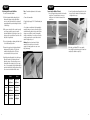
1
DX5e Quick Start Guide 1. Install Receiver 3. Bind Receiver A.Plug the bind plug into the receiver’s BATT/BIND port. In systems utilizing a separate battery pack and 3-wire switch, plug the bind plug into the charge jack. B. Power up the receiver. The LED on the receiver will be flashing. C.Move the sticks and switches on the transmitter to the desired failsafe positions (low throttle and neutral control positions). D.Pull and hold the Trainer Switch on the transmitter while turning the transmitter on. Release the trainer switch once the LEDs on the front of the transmitter flash. E.The LED on the receiver will go solid amber and the system will connect after several seconds. F. Remove the bind plug from the charge jack or bind port. Typical Electric - Rx uses the ESC for power. Example of AR500 installed in E-flite® Apprentice Though in general it is non-critical, optimum installation of the antenna is to orient the tip of the long antenna perpendicular to the short antenna. The tip on the long antenna should be a least 2 inches from the short antenna. A. Insert Bind Plug Elevator Stick UP Elevator Stick DOWN Aileron Stick LEFT Aileron Stick RIGHT Rudder Stick LEFT Rudder Stick RIGHT Typical Glow/Gas - uses receiver pack and 3-wire switch. 5. C ontrol Surface Check Turn on the transmitter followed by the receiver and check that the direction of each channel is correct. Use the servo reversing switches on the front of the transmitter to change the direction if necessary. Receiver pack and 3-wire switch 6. Re-Bind the System After you’ve set up your model, it’s important to re-bind the system so the true low throttle position is stored. If the signal is lost, the throttle servo will drive to a low throttle safe position. 7. R ange Check Tape antenna in place. Do not allow tip to touch metal. Example of AR500 installed in Hangar 9® Pulse™ XT 60 B. Apply power to system 30 paces (90 feet/28 meters) A, B. Insert bind plug into charge jack, apply power 2. Install AA Size Heavy-Duty or Alkaline Batteries Note: Observe polarity when installing batteries. Pull and hold the Trainer Switch Note: Continuing to hold the trainer switch during the binding process will prevent preset failsafe positions from being learned by the receiver. C, D. Pull trainer switch, turn power on 4. Test System Battery Voltage Lack of power to the receiver and servos is a leading cause of failure. If you are using a receiver pack, ensure that it is properly charged and check the voltage under load (HAN172). Do not fly if voltage is below 4.8V for a 4-cell pack. How to Range Check 1. With the model resting on the ground, stand 30 paces (approximately 90 feet/28 meters) away from the model. 2. Face the model with the transmitter in your normal flying position and pull and hold the Trainer Switch while toggling the HI/LO Rate Switch four times. The LEDs will flash and the alarm will sound indicating the system is in range check mode. 3. You should have total control of the model with the Trainer Switch pulled at 30 paces (90 feet/28 meters). 4. If control issues exist, call the Horizon Support Team at 1-877-504-0233 or go to horizonhobby.com to find a local Spektrum distributor in your country of service. In systems using a BEC, ensure that you are not driving more than the manufacturer’s recommended number of servos for your BEC/Speed control. If at anytime, the voltage should fall below the receiver’s operating threshold, an interruption in the link may occur followed by a blinking light on the receiver. A more accurate way to test a questionable setup is to measure the voltage per the instructions on page 17. N ote: If the receiver power is cycled without cycling the transmitter, a blinking light will also occur. In this case, this does not indicate a problem. Cycle the Tx power, and then the Rx, to reset the light. Leaders in Spread Spectrum Technology The Spektrum trademark is used with permission of Bachmann Industries, Inc. Revised 12/08 13639.1 Leaders in Spread Spectrum Technology 5-Channel Full Range DSM2™ 2.4GHz Radio System Table of Contents Spektrum’s DX5e 5-channel DSM2 Full Range System...................................... 2 DSM2 DuaLink® Technology............................. 4 Receiver Compatibility...................................... 4 Installing the Transmitter Batteries................... 5 Charging Batteries............................................. 5 Digital Trims...................................................... 6 Low Battery Alarm............................................ 6 Trainer............................................................... 7 Receiver Installation.......................................... 7 Binding.............................................................. 8 How to Range Test the DX5e............................. 9 AR500 Failsafe................................................ 10 HOW AR500 FAILSAFE WORKS...................... 10 Servo Reversing.............................................. 10 Hi/Lo Rate....................................................... 10 Elevon/ Delta mixing....................................... 11 Receiver Power System Requirements........... 11 Tips on Using 2.4GHz Systems....................... 12 General Information........................................ 13 Warranty Information...................................... 15 Instructions for Disposal of WEEE by Users in the European Union..................... 17 Optional Accessories....................................... 18 Spektrum’s DX5e 5-channel DSM2 Full Range System Spektrum’s DX5e 5-channel system incorporates 2.4GHz DSM2 technology offering full beyond-the-limits-of-sight range and is ideal for sport-sized electric, gas and glowpowered 5-channel or fewer airplanes. No longer will you have to wait for a frequency pin or be concerned that someone may inadvertently turn on to your same frequency. With Spektrum DSM2 technology, when you’re ready to fly simply turn on, and go flying! Transmitter Control Identification Antenna Trainer Switch HI/LO Rate Switch Channel 5 Switch Rudder and Elevator Stick Throttle and Aileron Stick Throttle Trim Elevator Trim Aileron Trim RudderTrim On/Off Switch Trainer Port Reversing Switches Mix Switch Charge Jack Mode 1 Antenna Trainer Switch HI/LO Rate Switch Channel 5 Switch Throttle and Rudder Stick Aileron and Elevator Stick Throttle Trim Elevator Trim Rudder Trim Aileron Trim On/Off Switch Trainer Port Charge Jack Reversing Switches Mix Switch Mode 2 2 SPEKTRUM DX5e • RADIO USER’S GUIDE SPEKTRUM DX5e • RADIO USER’S GUIDE 3 DSM2 DuaLink® Technology Receiver Compatibility Your DX5e transmits on the 2.4GHz band and utilizes DSM2™ second-generation Digital Spread Spectrum Modulation, giving beyond-visual range in all types and sizes of aircraft. Unlike conventional narrow band systems, Spektrum’s 2.4GHz digital DuaLink technology is virtually immune to internal and external radio interference. The DX5e is compatible with all current Spektrum™ and JR® brands of DSM® aircraft receivers. However, when using the DX5e with one of the Spektrum park flyer receivers, like the AR6000, AR6100, AR6100E, etc., it is imperative that these receivers be limited to flying Parkflyer-type aircraft. Installing the Transmitter Batteries The DX5e requires 4 heavy duty or alkaline AA batteries. Battery Installation Park flyer Receivers Included with your DX5e is an AR500 5-channel fullrange sport receiver. The DX5e transmitter simultaneously transmits on two frequencies and the AR500 receives both frequencies, creating dual RF paths. This dual path redundancy creates a bulletproof RF link. The AR500 features two aileron outputs making it convenient when using airplanes with two aileron servos. Charging Batteries If using rechargeable batteries (optional), it is imperative that you fully charge the transmitter prior to each flying session. To do so, using the optional wall charger, leave the charger and batteries connected overnight (16 hours). The optional charger (SPM9526) is designed to recharge your batteries at a rate of 150mA for the transmitter and 150mA for the receiver battery pack. Do not use this charger for equipment other than Spektrum transmitters that use 4-cell battery packs. The charging plug polarity may not be the same and equipment damage can result. During the charging operation, the charger’s temperature is slightly elevated. This is normal. Charger Pigtail for Transmitter • AR6000 • AR6100 • AR6100E • AR6300 Note: Optional NiCd or NiMH 1.2-volt AA rechargeable batteries can also be used. A charge jack is located on the right side of the transmitter for convenient recharging. Spektrum offers optional replacement NiMH rechargeable batteries, part number SPM9525. Full Range DSM2 Aircraft Receivers BLACK TO POSITIVE Remove the battery door and install 4 AA batteries. Make sure the polarity of each corresponds with the diagram in the battery holder. Replace the battery door. BLACK W/WHITE STRIPE TO NEGATIVE Spektrum Transmitter Charge Jack Polarity - • AR6200 • AR7000 + • AR9000 A charging jack is located on the right side of the transmitter. If rechargeable batteries are used they can be conveniently charged without removing them from the transmitter using the charge jack. • AR7100 4 • AR7100R • AR9100 SPEKTRUM DX5e • RADIO USER’S GUIDE SPEKTRUM DX5e • RADIO USER’S GUIDE 5 IMPORTANT: All Spektrum charge jacks are center-pin negative. This is the opposite of many chargers. Before using a charger make sure the connector is center-pin negative. This can be done using a voltmeter. Also unlike conventional radio systems that use 8 cells to power the transmitter, the DX5e uses 4 cells. This is due to the electronics being more efficient. When charging, be sure to use a charger designed for a 4-cell 4.8-volt battery pack when charging the transmitter. Digital Trims Trainer The DX5e features digital trims. Each time a trimmer is moved the servo output will change one step. If the trimmer is held, the output will scroll in that direction until the trimmer is released or the output reaches its end. The DX5e offers a trainer function that allows the transmitter to operate as a master or slave. The trainer switch is located on the back left of the transmitter. When using the trainer function, plug the trainer cord (SPM6805) into the trainer port in both the master (controlling) and the slave (training) transmitters. The master transmitter must have the power turned on and the slave transmitter must have the power turned off. Transmitter Polarity The center pin on all Spektrum transmitters is negative. Therefore, the center pin on all Spektrum chargers is negative, not positive. This is different from many other manufacturers’ chargers and radio systems. Beware of improper connections based on “color coded” wire leads, as they may not apply in this instance. You must make sure that the center pin of your Spektrum transmitter is always connected to the negative voltage of your charger for correct polarity hookup. Note: The DX5e trainer system is compatible with all JR and Spektrum transmitters. Receiver Installation Install the receiver using the same method you would use to install a conventional receiver in your aircraft. Typically, wrap the receiver in protective foam and fasten it in place using rubber bands or hook and loop straps. Alternately, in electric models, it’s acceptable to use thick double-sided foam tape to fasten the main receiver in place. Mount the antennas such that the tip of the feeder (long) antenna is perpendicular (90 degrees) to the short antenna and the antennas are at least 2 inches apart. Essentially, each antenna sees a different RF environment and this is key to maintaining a solid RF link. Master Throttle Trim Elevator Trim Rudder Trim The DX5e transmitter can be used as a master but the slave transmitter must have the same programming (i.e. reverse switch positions) as the master. Aileron Trim Mode 2 Slave When using the DX5e transmitter as a slave with another DX5e, it’s necessary to match all the reverse switch positions. Receiver Installation Elevator Trim Throttle Trim Rudder Trim Aileron Trim The AR500 incorporates dual receiver antennas, offering the security of dual path RF redundancy. By locating these antennas in slightly different locations in the aircraft, each antenna is exposed to its own RF environment, greatly improving path diversity (the ability for the receiver to see the signal in all conditions). The receiver features two aileron outputs making it convenient when installing the receiver in airplanes that have two aileron servos. Mode 1 Low Battery Alarm When the battery voltage drops below 4.7 volts, an alarm will sound and the voltage LEDs will flash. 6 SPEKTRUM DX5e • RADIO USER’S GUIDE SPEKTRUM DX5e • RADIO USER’S GUIDE 7 Binding The AR500 receiver must be bound to the transmitter before it will operate. Binding is the process of teaching the receiver the specific code of the transmitter so it will only connect to that specific transmitter. 2. Power the receiver by plugging in a receiver battery in any port on the receiver. Note that the LED on the receiver should be flashing, indicating that the receiver is in bind mode and ready to be bound to the transmitter. Note: RTF and Radio Systems are pre-bound at the factory. Rebinding is necessary if any settings are changed to ensure proper failsafe settings are achieved. 4. Pull and hold the trainer switch on the top of the transmitter while turning on the power switch. Release the trainer switch once the LEDs on the front of the transmitter flash, and a series of tones are heard. Within a few seconds the system should connect. Once connected the LED on the receiver will go solid indicating the system is connected. 1. To bind an AR500 to a DSM2 transmitter, insert the BATT/BIND port in the charge plug receptacle. Note: Continuing to hold the trainer switch during the binding process will prevent preset failsafe positions from being learned by the receiver. How to Range Test the DX5e Before each flying session, and especially with a new model, it is important to perform a range check. The DX5e incorporates a range testing system which, when placed in the RANGE CHECK mode with the trainer switch activated and held, reduces the output power, allowing a range check. Range Testing the DX5e 1. With the model restrained on the ground, stand 30 paces (approx. 90 feet/28 meters) away from the model. Note: Prior to performing the range check ensure the correct failsafe stick positions are established. 2. Face the model with the transmitter in your normal flying position. Pull and hold the trainer switch while toggling the HI/LO Rate Switch four times. The LEDs will flash and the alarm will sound indicating the system is in range check mode. Shown above using a separate receiver pack Note: When binding using a switch harness and separate receiver pack, a three-wire switch harness must be used such as SPM9530. (Not shown) You may need to purchase the Male/Female bind plug SPM6803 in addition to the switch harness. Note: The trainer switch must be held the entire time during the range check process; releasing the trainer switch will exit the range check mode. Trainer Switch 5. Remove the bind plug from the BATT/BIND port on the receiver before you power off the receiver and store it in a convenient place. 6. After you’ve set up your model, it’s important to rebind the system so the true low throttle and neutral control surface positions are programmed. Note: To bind an aircraft with an electronic speed controller that powers the receiver through the throttle channel (ESC/BEC), insert the bind plug into the BATT/ BIND port in the receiver and the throttle lead into the throttle port. Proceed to Step #2. Shown above using an ESC/BEC and a flight pack HI/LO Rate Switch 3. You should have total control of the model with the trainer switch pulled at 30 paces (90 feet/28 meters). 4. If control issues exist, call the Horizon Product Support Team at 1 877 504 0233 or go to horizonhobby.com to find a local Spektrum distributor for service in your country. 3. Move the sticks and switches on the transmitter to the desired AR500 failsafe positions (low throttle and neutral control positions). 30 paces (90 feet/28 meters) 8 SPEKTRUM DX5e • RADIO USER’S GUIDE SPEKTRUM DX5e • RADIO USER’S GUIDE 9 AR500 Failsafe Servo Reversing Elevon/ Delta mixing • Prevents unintentional electric motor response on start-up. • Eliminates the possibility of over-driving servos on start-up. • Establishes low-throttle failsafe if the RF signal is lost. • The AR500 removes servo output pulses to all channels except the throttle channel during failsafe. • The AR500 throttle failsafe position is stored via the throttle stick position on the transmitter. The DX5e features servo reversing on channels 1-4. The switches are located at the lower front of the transmitter and are used to select the direction of each channel. Use a small screwdriver to change the switch position to normal or reverse. The DX5e offers an Elevon mix. Elevon (also called delta wing) mixing combines the function of ailerons with the function of the elevator to allow precise control of both roll and pitch for delta wing aircraft. To activate the Elevon mix, move the mix switch to the on (up) position. Elevon Wing Type Connection AILE Servo Port (Left Elevon) How AR500 Failsafe Works ELEV Servo Port (Right Elevon) Receiver Power Only • In electric aircraft, when the receiver only is turned on (no transmitter signal is present), the throttle channel has no output, to avoid operating or arming the electronic speed control. • In glow-powered models, the throttle servo receives no input so it remains in its current position. Note: Some analog servos will coast slightly even though there is no signal present. This is normal. • All other channels will move to the positions set during binding After Connection • When the transmitter is turned on, and after the receiver connects to the transmitter, normal control of all channels occurs. • After the system makes a connection, if loss of signal occurs, the AR500 failsafe drives the throttle servo only to its preset failsafe position (low throttle) that was set during binding. • All other channels receive no output pulses/ commands, and are not active during failsafe. • ELEV servo port (right aileron) • AILE servo port (left aileron) Hi/Lo Rate The DX5e offers a high/low rate function on aileron, elevator and rudder. When the HI/LO rate switch is in the upper position or “HI” position, 100% travel is achieved on the aileron, elevator and rudder channels. When the switch is in the lower position a reduced travel of 70% is achieved on the aileron, elevator and rudder channels. This is useful allowing the aircraft to have a high control rate (switch in the “HI” position) for aggressive maneuvers and a low control rate (switch in “LO” position) for smooth, precise maneuvers. Note: If proper servo direction cannot be achieved with the servo reversing switches, swap the servo input leads from AILE to ELEV or vice versa. SPEKTRUM DX5e • RADIO USER’S GUIDE With all radio installations, it is vital the onboard power system provides adequate power without interruption to the receiver even when the system is fully loaded (servos at maximum flight loads). This becomes especially critical with giant-scale models that utilize multiple high-torque/ highcurrent servos. Inadequate power systems that are unable to provide the necessary minimum voltage to the receiver during flight loads have become the number-one cause of in-flight failures. Some of the power system components that affect the ability to properly deliver adequate power include: the selected receiver battery pack (number of cells, capacity, cell type, state of charge), switch harness, battery leads, regulator (if used) and, unless it’s a regulator, power bus (if used). While a Spektrum receiver’s minimum operational voltage is 3.5 volts, it is highly recommended the system be tested per the guidelines below to a minimum acceptable voltage of 4.8 volts during ground testing. This will provide head room to compensate for battery discharging or if the actual flight loads are greater than the ground test loads. Recommended Power System Guidelines 1. When setting up large or complex aircraft with multiple high-torque servos, it’s highly recommended that a current and voltmeter (Hangar 9 HAN172) be used. Plug the voltmeter in an open channel port in the receiver and, with the system on, load the control surfaces (apply pressure with your hand) while monitoring the voltage at the receiver. The voltage should remain above 4.8 volts even when all servos are heavily loaded. 2. With the current meter in line with the receiver battery lead, load the control surfaces (apply pressure with your hand) while monitoring the current. The maximum continuous recommended current for a single heavy-duty servo/battery lead is three amps while short-duration current spikes of up to five amps are acceptable. Consequently, if your system draws more than three amps continuous or five amps for short durations, a single battery pack with a single switch harness plugged into the receiver for power will be inadequate. It will be necessary to use multiple packs with multiple switches and multiple leads plugged into the receiver. • High 100% rate on aileron, elevator and rudder • Low 70% rate on aileron, elevator and rudder 10 Receiver Power System Requirements SPEKTRUM DX5e • RADIO USER’S GUIDE 11 3. If using a regulator, it’s important the above tests are done for an extended period of 5 minutes. When current passes through a regulator, heat is generated. This heat causes the regulator to increase resistance, which in turn causes even more heat to build up (thermal runaway). While a regulator may provide adequate power for a short duration, it’s important to test its ability over time as the regulator may not be able to maintain voltage at significant power levels. 4. For really large aircraft or complex models (for example 35% and larger or jets), multiple battery packs with multiple switch harnesses are necessary or in many cases one of the commercially available power boxes/ busses is recommended. No matter what power systems you choose, always carry out test #1 above making sure that the receiver is constantly provided with 4.8 volts or more under all conditions. 5. The latest generation of Nickel-Metal Hydride batteries incorporates a new chemistry mandated to be more environmentally friendly. These batteries, when charged with peak detection fast chargers, have a tendency to false peak (not fully charge) repeatedly. These include all brands of NiMH batteries. If using NiMH packs be especially cautious when charging making absolutely sure that the battery is fully charged. It is recommended to use a charger that can display total charge capacity. Note the number of mAh put into a discharged pack to verify it has been charged to full capacity. Tips on Using 2.4GHz Systems Your DSM2 equipped 2.4GHz system is intuitive to operate, functioning nearly identically to FM systems. Following are a few common questions from customers: 1. Q: Which do I turn on first, the transmitter or the receiver? A: It doesn’t matter, although it is suggested to turn the transmitter on first. If the receiver is turned on first, the throttle channel doesn’t put out a pulse position at this time, preventing the arming of electronic speed controllers, or in the case of an engine powered aircraft, the throttle servo remains in its current position. When the transmitter is then turned on the transmitter scans the 2.4GHz band and acquires two open channels. Then the receiver that was previously bound to the transmitter scans the band and finds the GUID (Globally Unique Identifier code) stored during binding. The system then connects and operates normally. If the transmitter is turned on first, the transmitter scans the 2.4GHz band and acquires two open channels. When the receiver is turned on, the receiver scans the 2.4GHz band looking for the previously stored GUID. When it locates the specific GUID code and confirms uncorrupted repeatable packet information, the system connects and normal operation takes place. Typically this takes 2 to 6 seconds. 2. Q: Sometimes the system takes longer to connect and sometimes it doesn’t connect at all. Why? A In order for the system to connect (after the receiver is bound), the receiver must receive a large number of continuous (one after the other) uninterrupted perfect packets from the transmitter. This process is purposely critical of the environment ensuring that it’s safe to fly when the system does connect. If the transmitter is too close to the receiver (less that 4 feet) or if the transmitter is located near metal objects (metal transmitter case, the bed of a truck, the top of a metal work bench, etc.) connection will take longer. In some cases connection will not occur as the system is receiving reflected 2.4GHz energy from itself and is interpreting this as unfriendly noise. Moving the system away from metal objects or moving the transmitter away from the receiver and powering the system up again will cause a connection to occur. This only happens during the initial connection. Once connected the system is locked, and should a loss of signal occur (failsafe), the system connects immediately (4ms) when signal is regained. 12 SPEKTRUM DX5e • RADIO USER’S GUIDE 3. Q: I’ve heard that the DSM system is less tolerant of low voltage. Is this correct? A: All DSM receivers have an operational voltage range of 3.5 to 9 volts. With most systems this is not a problem as in fact most servos cease to operate at around 3.8 volts. When using multiple high-current draw servos with a single or inadequate battery/ power source, heavy momentary loads can cause the voltage to dip below this 3.5-volt threshold causing the entire system (servos and receiver) to brown out. When the voltage drops below the low voltage threshold (3.5 volts), the DSM receiver must reboot (go through the start up process of scanning the band and finding the transmitter) and this can take several seconds. 4. Q: Sometimes my receiver loses its bind and won’t connect, requiring rebinding. What happens if the bind is lost in flight? A: The receiver will never lose its bind unless it’s instructed to. It’s important to understand that during the binding process the receiver not only learns the GUID (code) of the transmitter but the transmitter learns and stores the type of receiver that it’s bound to. If the trainer switch is pulled on the transmitter at any time and the transmitter is turned on, the transmitter looks for the binding protocol signal from a receiver. If no signal is present, the transmitter no longer has the correct information to connect to a specific receiver and in essence the transmitter has been “unbound” from the receiver. We’ve had several customers using transmitter stands or trays that unknowingly depress the bind button. The system is then turned on, losing the necessary information to allow the connection to take place. We’ve also had customers that didn’t fully understand the range test process and pull the trainer switch before turning on the transmitter, also causing the system to “lose its bind.” If the system fails to connect, one of the following has occurred: • The transmitter is near conductive material (transmitter case, truck bed, etc.) and the reflected 2.4GHz energy is preventing the system from connecting. (See #2 above) • The trainer switch was pulled and the radio was previously turned on knowingly (or unknowingly), causing the transmitter to no longer recognize the receiver. SPEKTRUM DX5e • RADIO USER’S GUIDE General Information FCC Information This device complies with part 15 of the FCC rules. Operation is subject to the following two conditions: (1) This device may not cause harmful interference, and (2) this device must accept any interference received, including interference that may cause undesired operation. Caution: Changes or modifications not expressly approved by the party responsible for compliance could void the user’s authority to operate the equipment. This product contains a radio transmitter with wireless technology which has been tested and found to be compliant with the applicable regulations governing a radio transmitter in the 2.400GHz to 2.4835GHz frequency range. Servo Precautions • Do not lubricate servo gears or motors. • Do not overload retract servos during retracted or extended conditions. Make sure they are able to travel their full deflection. Overloading or stalling a servo can cause excessive current drain. • Make sure all servos move freely through their rotations and no linkages hang up or bind. A binding control linkage can cause a servo to draw excessive current. A stalled servo can drain a battery pack in a matter of minutes. • Correct any control surface “buzz” or “flutter” as soon as it is noticed in flight, as this condition can destroy the feedback potentiometer in the servo. It may be extremely dangerous to ignore such “buzz” or “flutter.” • Use the supplied rubber grommets and brass servo eyelets when mounting your servos. Do not overtighten the servo mounting screws, as this negates the dampening effect of the rubber grommets. • Ensure the servo horn is securely fastened to the servo. Use only the servo arm screws provided; the size is different from other manufacturers. • Discontinue to use servo arms when they become “yellowed” or discolored. Such servo arms may be brittle and can snap at any time, possibly causing the aircraft to crash. • Check all related mounting screws and linkages frequently. Aircraft often vibrate, causing linkages and screws to loosen. 13 General Notes Federal Aviation Administration Radio controlled models are a great source of pleasure. Unfortunately, they can also pose a potential hazard if not operated and maintained properly. Purpose It is imperative to install your radio control system correctly. Additionally, your level of piloting competency must be high enough to ensure that you are able to control your aircraft under all conditions. If you are a newcomer to radio controlled flying, please seek help from an experienced pilot or your local hobby store. Safety Do’s and Don’ts for Pilots • Ensure that your batteries have been properly charged prior to your initial flight. • Keep track of the time the system is turned on so you will know how long you can safely operate your system. • Perform a ground range check prior to the initial flight of the day. See the “Daily Flight Checks Section” for information. • Check all control surfaces prior to each takeoff. • Do not fly your model near spectators, parking areas or any other area that could result in injury to people or damage of property. • Do not fly during adverse weather conditions. Poor visibility can cause disorientation and loss of control of your aircraft. Strong winds can cause similar problems. • Do not point the transmitter antenna directly toward the model. The radiation pattern from the tip of the antenna is inherently low. • Do not take chances. If at any time during flight you observe any erratic or abnormal operation, land immediately and do not resume flight until the cause of the problem has been ascertained and corrected. Safety can never be taken lightly. This advisory outlines safety standards for operations of model aircraft. We encourage voluntary compliance with these standards. Background Attention has been drawn to the increase in model aircraft operation. There is a need for added caution when operating free flight and radio controlled craft in order to avoid creating a noise nuisance or a potential hazard to full-scale aircraft and persons and/or property on the surface. Operating Standards Modelers generally are concerned with safety and exercise good judgment when flying model aircraft. However, in the interest of safer skies, we encourage operators of radio controlled and free flight models to comply with the following standards: a. Exercise vigilance in locating full-scale aircraft (get help if possible) so as not to create a collision hazard. b. Select an operating site at sufficient distance from populated areas so you do not create a noise problem or a potential hazard. c. Do not fly higher than 400 feet above the surface. d. Always operate more than three miles from the boundary of an airport unless you are given permission to be closer by the appropriate air traffic control facility in the case of an airport for which a control zone has been designated or by the airport manager in the case of other airports. e. Do not hesitate to ask for assistance in complying with these guidelines at the airport traffic control tower or air route traffic control center nearest the site of your proposed operation. Daily Flight Checks Warranty Information 1. Check the battery voltage on both the transmitter and the receiver battery packs. Do not fly below 4.7V on the transmitter or below 4.7V on the receiver. To do so can crash your aircraft. Warranty Period Note: When you check these batteries, ensure that you have the polarities correct on your expanded scale voltmeter. 2. Check all hardware (linkages, screws, nuts, and bolts) prior to each day’s flight. Be sure that binding does not occur and that all parts are properly secured. 3. Ensure that all surfaces are moving in the proper manner. 4. Perform a ground range check before each day’s flying session. 5. Prior to starting your aircraft, turn off your transmitter, then turn it back on. Do this each time you start your aircraft. If any critical switches are on without your knowledge, the transmitter alarm will warn you at this time. 6. Check that all trim levers are in the proper location. 7. All servo pigtails and switch harness plugs should be secured in the receiver. Make sure that the switch harness moves freely in both directions. Director, Air Traffic Service Federal Aviation Administration, Washington, D.C. SPEKTRUM DX5e • RADIO USER’S GUIDE Limited Warranty (a) This warranty is limited to the original Purchaser (“Purchaser”) and is not transferable. REPAIR OR REPLACEMENT AS PROVIDED UNDER THIS WARRANTY IS THE EXCLUSIVE REMEDY OF THE PURCHASER. This warranty covers only those Products purchased from an authorized Horizon dealer. Third party transactions are not covered by this warranty. Proof of purchase is required for warranty claims. Further, Horizon reserves the right to change or modify this warranty without notice and disclaims all other warranties, express or implied. (b) Limitations- HORIZON MAKES NO WARRANTY OR REPRESENTATION, EXPRESS OR IMPLIED, ABOUT NON-INFRINGEMENT, MERCHANTABILITY OR FITNESS FOR A PARTICULAR PURPOSE OF THE PRODUCT. THE PURCHASER ACKNOWLEDGES THAT THEY ALONE HAVE DETERMINED THAT THE PRODUCT WILL SUITABLY MEET THE REQUIREMENTS OF THE PURCHASER’S INTENDED USE. (c) Purchaser Remedy- Horizon’s sole obligation hereunder shall be that Horizon will, at its option, (i) repair or (ii) replace, any Product determined by Horizon to be defective. In the event of a defect, these are the Purchaser’s exclusive remedies. Horizon reserves the right to inspect any and all equipment involved in a warranty claim. Repair or replacement decisions are at the sole discretion of Horizon. This warranty does not cover cosmetic damage or damage due to acts of God, accident, misuse, abuse, negligence, commercial use, or modification of or to any part of the Product. This warranty does not cover damage due to improper installation, operation, maintenance, or attempted repair by anyone other than Horizon. Return of any goods by Purchaser must be approved in writing by Horizon before shipment. Information Provided By 14 Horizon Hobby, Inc., (Horizon) warranties that the Products purchased (the “Product”) will be free from defects in materials and workmanship at the date of purchase by the Purchaser. SPEKTRUM DX5e • RADIO USER’S GUIDE 15 Damage Limits Inspection or Repairs HORIZON SHALL NOT BE LIABLE FOR SPECIAL, INDIRECT OR CONSEQUENTIAL DAMAGES, LOSS OF PROFITS OR PRODUCTION OR COMMERCIAL LOSS IN ANY WAY CONNECTED WITH THE PRODUCT, WHETHER SUCH CLAIM IS BASED IN CONTRACT, WARRANTY, NEGLIGENCE, OR STRICT LIABILITY. Further, in no event shall the liability of Horizon exceed the individual price of the Product on which liability is asserted. As Horizon has no control over use, setup, final assembly, modification or misuse, no liability shall be assumed nor accepted for any resulting damage or injury. By the act of use, setup or assembly, the user accepts all resulting liability. Law: These Terms are governed by Illinois law (without regard to conflict of law principals). If this Product needs to be inspected or repaired, please call for a Return Merchandise Authorization (RMA). Pack the Product securely using a shipping carton. Please note that original boxes may be included, but are not designed to withstand the rigors of shipping without additional protection. Ship via a carrier that provides tracking and insurance for lost or damaged parcels, as Horizon is not responsible for merchandise until it arrives and is accepted at our facility. A Service Repair Request is available at www.horizonhobby.com on the “Support” tab. If you do not have internet access, please include a letter with your complete name, street address, email address and phone number where you can be reached during business days, your RMA number, a list of the included items, method of payment for any non-warranty expenses and a brief summary of the problem. Your original sales receipt must also be included for warranty consideration. Be sure your name, address, and RMA number are clearly written on the outside of the shipping carton. Safety Precautions Warranty Inspection and Repairs If you as the Purchaser or user are not prepared to accept the liability associated with the use of this Product, you are advised to return this Product immediately in new and unused condition to the place of purchase. This is a sophisticated hobby Product and not a toy. It must be operated with caution and common sense and requires some basic mechanical ability. Failure to operate this Product in a safe and responsible manner could result in injury or damage to the Product or other property. This Product is not intended for use by children without direct adult supervision. The Product manual contains instructions for safety, operation and maintenance. It is essential to read and follow all the instructions and warnings in the manual, prior to assembly, setup or use, in order to operate correctly and avoid damage or injury. Questions, Assistance and Repairs Your local hobby store and/or place of purchase cannot provide warranty support or repair. Once assembly, setup or use of the Product has been started, you must contact Horizon directly. This will enable Horizon to better answer your questions and service you in the event that you may need any assistance. For questions or assistance, please direct your email to [email protected], or call 877.504.0233 toll free to speak to a Product Support. United States Electronics and engines requiring inspection or repair should be shipped to the following address: Horizon Service Center 4105 Fieldstone Road Champaign, Illinois 61822 All other products requiring warranty inspection or repair should be shipped to the following address: Horizon Support Team 4105 Fieldstone Road Champaign, Illinois 61822 Please call 877.504.0233 or e-mail us at productsupport@ horizonhobby.com with any questions or concerns regarding this product or warranty. United Kingdom Electronics and engines requiring inspection or repair should be shipped to the following address: Horizon Hobby UK Units 1-4 Ployters Rd Staple Tye Southern Way Harlow Essex CM18 7NS United Kingdom To receive warranty service, you must include your original sales receipt verifying the proof-of-purchase date. Provided warranty conditions have been met, your Product will be repaired or replaced free of charge. Repair or replacement decisions are at the sole discretion of Horizon Hobby. Non-Warranty Repairs Should your repair not be covered by warranty the repair will be completed and payment will be required without notification or estimate of the expense unless the expense exceeds 50% of the retail purchase cost. By submitting the item for repair you are agreeing to payment of the repair without notification. Repair estimates are available upon request. You must include this request with your repair. Non-warranty repair estimates will be billed a minimum of ½ hour of labor. In addition you will be billed for return freight. Please advise us of your preferred method of payment. Horizon accepts money orders and cashiers checks, as well as Visa, MasterCard, American Express, and Discover cards. USA: Please call 1 877 504 0233 or visit horizonhobby.com to find our distributor for your country for support with any questions or concerns regarding this product or warranty. UK: Please call +44 1279 641 097 or sales@ horizonhobby.co.uk with any questions or concerns regarding this product or warranty. Germany: Please call +49 4121 46199 66 or [email protected] with any questions or concerns regarding this product or warranty. Instructions for Disposal of WEEE by Users in the European Union This product must not be disposed of with other waste. Instead, it is the user’s responsibility to dispose of their waste equipment by handing it over to a designated collection point for the recycling of waste electrical and electronic equipment. The separate collection and recycling of your waste equipment at the time of disposal will help to conserve natural resources and ensure that it is recycled in a manner that protects human health and the environment. For more information about where you can drop off your waste equipment for recycling, please contact your local city office, your household waste disposal service or where you purchased the product. Please call +44 1279 641 097 or [email protected] with any questions or concerns regarding this product or warranty. Germany Electronics and engines requiring inspection or repair should be shipped to the following address: Horizon Technischer Service Otto Hahn Str. 9a 25337 Elmshorn Germany Please call +49 4121 46199 66 or service@horizonhobby. de with any questions or concerns regarding this product or warranty. If you choose to pay by credit card, please include your credit card number and expiration date. Any repair left unpaid or unclaimed after 90 days will be considered abandoned and will be disposed of accordingly. Please note: non-warranty repair is only available on electronics and model engines. 16 SPEKTRUM DX5e • RADIO USER’S GUIDE SPEKTRUM DX5e • RADIO USER’S GUIDE 17 Optional Accessories Servos & Servo Accessories Batteries SPMDSP60..............6.0G Super Sub-Micro Digital Programmable Servo SPM9520.................1100MAH 4.8V NICD RECEIVER PACK SPM9525.................1500mAh Ni-MH AA 4Pk SPMB1500NM.........1500MAH 4.8V NIMH RECEIVER PACK SPMB1650NM.........1650MAH 6.0V NIMH RECEIVER PACK SPMB2150NM.........2150MAH 6.0V NIMH RECEIVER PACK SPMB2700NM.........2700MAH 6.0V NIMH RECEIVER PACK SPMB4500NM.........4500MAH 6.0V NIMH RECEIVER PACK Chargers SPM9526.................150mA Wall Charger w/TX Adapter Remote Receiver Extensions SPM9010.................REMOTE RECEIVER EXTENSION 6-inch SPM9011.................REMOTE RECEIVER EXTENSION 9-inch SPM9012.................REMOTE RECEIVER EXTENSION 12-inch SPM9013.................REMOTE RECEIVER EXTENSION 24-inch SPM9014.................REMOTE RECEIVER EXTENSION 36-inch SPMDSP..................DIGITAL SERVO PROGRAMMER SPMDSP60J............6.0G Super Sub-Micro Digital Programmable Servo JST SPMDSP601............GEAR SET DSP60 SPMDSP602............CASE SET DSP60 SPMDSP603............STD ARM SET W/SCREWS, FINE SPLINE DSP60 SPMDSP604............3D ARM SET W/SCREWS, FINE SPLINE DSP60 SPMDSP75..............7.5GM Super Sub-Micro Digital Programmable Servo SPMDSP751............GEAR SET DSP75 SPMDSP752............CASE SET DSP75 SPMDSP753............STD ARM SET W/SCRWS FINE SPLINE DSP75 SPMDSP754............3D ARM SET W/SCREW FINE SPLINE DSP75 Voltage Regulators & Accessories SPMVR5203............VR5203 DUAL OUTPUT REGULATOR SPMVR6010............VR6010 VOLTAGE REGULATOR 10A, 6V SPM6820.................SOFT SWITCH: AR9100, VR6010 SPM6821.................CHARGEADAPT: VR6010, AR7100/R SPM6822.................COOLING FAN: VR6010 Switch Harnesses SPM9530.................3 WIRE SWITCH HARNESS SPM9531.................DUAL I/O 3 WIRE SWITCH HARNESS 18 SPEKTRUM DX5e • RADIO USER’S GUIDE SPEKTRUM DX5e • RADIO USER’S GUIDE 19 Leaders in Spread Spectrum Technology US Address: 4105 Fieldstone Road Champaign, Illinois 61822 (877) 504-0233 UK Address: Horizon Hobby UK Units 1–4 Ployters Rd Staple Tye Southern Way Harlow Essex CM18 7NS United Kingdom+44 1279 641 097 www.horizonhobby.co.uk German Address: Horizon Deutschland GmbH Otto Hahn Strasse 9A Elmshorn, Germany +49 4121 46199 60 www.horizonhobby.de © 2008 Horizon Hobby, Inc. www.horizonhobby.com www.spektrumrc.com © 2008 DSM and DSM2 are trademarks or registered trademarks of Horizon Hobby, Inc. The Spektrum™ trademark is used with permission of Bachmann Industries, Inc. Spektrum radios and accessories are exclusively available from Horizon Hobby, Inc. 13118.2 RTF Instruction Manual ParkZone® products are distributed exclusively by Horizon Hobby, Inc. 4105 Fieldstone Road Champaign, IL 61822 Horizon Hobby UK Units 1-4 Ployters Rd Staple Tye Southern Way Harlow Essex CM18 7NS United Kingdom Horizon Hobby Deutschland GmbH Otto Hahn Str. 9a 25337 Elmshorn Germany The Spektrum trademark is used with permission of Bachmann Industries, Inc. © 2008 Horizon Hobby, Inc. parkzone.com 13253 Charge-and-Fly™ Park Flyer Wingspan: 78.74 in (2 meters) Length: 44.7 in (1137mm) Weight w/Battery: 30 oz Radio: Spektrum DX5e w/AR500 full range receiver Battery: 11.1V 1300mAh Li-Po Motor: PKZ 480-size, 960Kv brushless outrunner ESC: E-flite 30A brushless ESC with Switch-Mode BEC FCC Statement Radian Instruction Manual The experience of flying just got better. The ParkZone Radian™ encompasses all the benefits that ParkZone pilots have known to love. Experience the true essence of flight while quietly gliding on thermals of air—only using the motor to regain altitude, making for much longer flight times than traditional electric aircraft. The Radian’s large wingspan and elliptical dihedral design improves flight performance and visibility from the ground, while the 3-channel control allows for the ultimate in precision when controlling throttle, rudder, and elevator. With 2.4GHz radio technology, you can fly without worry or risk of interference. This eco-friendly alternative provides less noise for a relaxing day out at your local park or the great outdoors. The Radian is constructed from durable Z-Foam™ for the perfect balance of weight and durability. Its design boasts a large 2-meter wingspan and plug-in wings for easy transportation and storage. The Radian comes equipped with a 480 brushless motor, Spektrum™ DX5e transmitter and AR500 full range receiver for the ultimate soaring experience. Lightweight Z-Foam construction also ensures durability, making repairs simple and quick. Of course, every ParkZone plane comes out of the box ready to fly. ® 3 The Radian delivers the great looks and the immediate gratification ParkZone plane owners have grown to love, while Spektrum’s innovative radio technology provides you with the control and reliability required to keep you flying at the greatest heights. This device complies with part 15 of the FCC rules. Operation is subject to the following two conditions: (1) This device may not cause harmful interference, and (2) this device must accept any interference received, including interference that may cause undesired operation. Caution! Changes or modifications not expressly approved by the party responsible for compliance could void the user’s authority to operate the equipment. Instructions for Disposal of WEEE by Users in the European Union This product must not be disposed of with other waste. Instead, it is the user’s responsibility to dispose of their waste equipment by handing it over to a designated collections point for the recycling of waste electrical and electronic equipment. The separate collection and recycling of your waste equipment at the time of disposal will help to conserve natural resources and ensure that it is recycled in a manner that protects human health and the environment. For more information about where you can drop off your waste equipment for recycling, please contact your local city office, your household waste disposal service or where you purchased the product. 4 Simple Soaring One of the most fascinating and interesting segments of RC flying is Soaring. Finding a thermal and rising without power to unlimited heights is both exhilarating and rewarding. Once the Radian is up to altitude, one will be able to soar for hours relying only on thermal currents and wind to stay aloft. With the current trend towards an eco-friendly society, thermal soaring is free energy and fits well with the environmentally conscious consumer. Gliders were actually man’s first step to powered flight. The Wright brothers used gliders extensively to gather the much needed flight data that allowed them to eventually achieve powered flight. In essence, a glider is defined by the fact it continually descends. NASA space shuttles are in fact gliders by definition. Many of the troop carriers in World War II were also classified as gliders. Often gliders are confused with sailplanes, yet they have completely different functions. A sailplane is similar to a glider, however, there is one primary difference. A sailplane can actually soar—meaning it can rise above its initial launch height. In the late 1920s and early ’30s, Germany led the world with sailplane designs. This was partly due to restrictions placed on them from World War I, when they could not produce powered aircraft. Due to this, some wonderful innovations in sailplane designs were made, and some argue that it was this period that led to our current sailplane designs and theories. With modern sailplane designs, it is not uncommon for fullsize sailplanes to stay aloft for up to 8 hours and cover 1000 miles while averaging over 100 mph. Smaller model sailplanes can fly for long periods using similar flight theories that full-size sailplanes use. If you have never experienced thermal soaring with a sailplane before, you’re really going to enjoy the Radian’s great soaring capabilities and experience the wonderful sport of RC thermal soaring. What Are Thermals? The first step to thermal flying is to have a basic understanding of what thermals are and how they work. If you have some concept of how a thermal works it will help you know where to search for them. A thermal is basically rising air. The temperature of the ground is not consistent. Different textures, colors and even weather conditions can cause uneven ground temperature. The warmer ground temperatures heat up and form a warm air bubble. At this stage, the bubble will hug the ground until something breaks the surface tension to release it, much like a soap bubble breaking away from the water’s surface. Once tripped, 5 perhaps by a tree line or building, the thermal bubble then rises up, continuing to gain energy until it is fully developed many thousands of feet above. Thermals are typically stronger later in the day because the ground has had more time to generate heat. There are still thermals in the morning and evening, but they behave differently. Morning thermals are very narrow, meaning they have a small diameter, and do not typically go very high (20–400 feet). However, there are many small thermals in the morning, and it is recommended that you learn at this time of the day. Morning thermals are very defined yet are safe, as they typically don’t go too high and are not as violent as fully developed thermals. Another benefit is there are many smaller thermals close together in the morning and this will allow you to hop from one thermal to another with ease. Evening thermals are typically large warm air masses, meandering through the sky. They are usually very smooth with soft edges. The middle of the day (noon to 4 p.m.) is when the thermals are at their strongest. The downside is that with every thermal there is also sink. Sink is the surrounding air that is left by the thermal leaving the ground. Typically sink is on the upwind side of the thermal. Sink is created when the warm air has been displaced; colder descending air will fill the area when the warm air has receded. Sink is not necessarily a bad thing—because where there is sink there is also lift close by. The trick is to find lift before you have to land. How to Catch a Thermal Always have a planned search pattern when looking for thermals. Even the most seasoned thermal competition pilot will have a search plan before launching. This is one of the basics of thermal flying. If you have a plan, based on good sound thermal logic, chances are you will more than likely find a thermal. Thermals don’t typically stay in the same location for long, so maintaining a consistent pattern is important to ensure as much ground as possible is covered before landing. Many people just fly straight upwind. Working in an “S” pattern will increase the searched surface. Keep working the Radian upwind to cover a lot more sky for the same loss of height. Also, be on the lookout for ground markers. Although thermals cannot be seen, things that identify them can. Wind direction and velocity are great thermal indicators. Often the colder descending air filling in the hole that the thermal created when it left the ground will be a good indication as to where thermals may be. If the wind has a distinct change of direction, there is a good chance of a nearby thermal. The same would apply if the wind shifted to blow from the right. There would be a good chance the thermal would be to the left and slightly behind you. If you feel the wind strength increase, yet it continues blowing straight into your face, then the thermal is directly behind you. Finally, if the wind reduces in velocity, or even stops from a steady breeze, then the thermal is either ahead of you or right above you. Basically the thermal will be in the direction that the wind is blowing towards. Always pay attention to the general wind direction and look for changes in both its direction and velocity as signs for thermals. Other ground signs are birds. Many birds are capable of soaring, and you will often see them soaring on the thermals. Before launching, always check for birds. Pay close attention to how they are flying or if they are flapping hard—chances are they are also looking for lift. If they are soaring without flapping, then there is a good chance they are in lift. Birds also like to feed on small insects. As thermals initiate from the ground, often they will suck up small insects into the air. Birds will often feed on these insects and indicate another sign that there is lift. If you see birds flying in circles, almost in a feeding frenzy, there is a chance that lift is in their proximity. Another idea that works well is to fly over areas that are darker. Often a freshly plowed field, a parking lot, dirt—anything with a dark color will generate more heat—could also be a good source of generating thermals. One little test you may like to do is to paint various colors on a sheet of paper and place it in the sun. After 30 minutes or so, go and check which colors have created the most heat. Once you know what colors make the most heat, look for natural areas on the ground that match these colors and use those as locations for thermal hunting. What to Do When You Find a Thermal The first thing one needs to be absolutely sure of is that a lift has truly been found. Often a sailplane may find what is called a stick thermal, meaning you may have been carrying some additional speed and the model will climb by pitching upward. One of the best signals when the model is truly in lift is it will slightly speed up and the nose of the aircraft will be down slightly. The model will feel more agile and responsive. Once lift is found, start circling in a moderate circle (50–75 foot radius). Then determine the size of the thermal. If the Radian drops on one side of the thermal and is more buoyant on the other as it circles, it has reached the boundary of the thermal. The parameters of most thermals are clearly marked by the downward flowing air. The center has fast rising air and the outside has downward rolling air (often called the edge of the thermal or the thermal wall). In the middle of the day when thermals are at their strongest, the thermal wall can be very distinct and violent, yet in the morning and late evening they are much softer. The objective is to make sure one is completely inside the thermal. This is called centering or coring the thermal. You will need to constantly make adjustments to keep in the center of the thermal. Maintain climb all the way around each 360-degree circle. Often, especially if it is a windy day, thermals will drift with the wind. Most will travel directly downwind. One thing to remember is your Radian will also drift with the wind, especially when circling, so once the core of the thermal is established, the Radian will naturally drift with the thermal. One mistake people make is they don’t allow their model to drift with the thermal, hence falling out of the front or side of the thermal as it drifts downwind. Slope and Alpine Lift Another form of soaring is slope lift. This lift is caused by wind rushing over a hill, cliff or any solid land mass that has more than 30 degrees of slope. As the air hits the hill or slope, it is redirected in an upward motion, thus creating lift. The best example of this is hang gliders that are soaring on the cliff faces. They maintain flight by soaring on the updrafts created by the sea breezes hitting the cliffs and creating what is known as slope lift. This sort of soaring is a lot of fun with your Radian, as you can always motor back to a safe landing if the lift falls away. The important thing to understand with slope-type lift is the wind must be almost directly blowing up the face of the hill or slope. Any more than a 20-degree variation may cause more turbulence than actual lift. Alpine soaring has been popular in Europe and is also becoming popular in the US. It is the extreme end of thermal soaring. As thermals develop deep on the valley floor, they rise up the mountainside reaching their climax at the top of the mountain. This is often marked by a strong breeze blowing at the top of the mountain, which is in fact a fully developed thermal. One of the benefits of the Radian is that it has power assistance. Even though it does have an electric motor that will allow quite a steep climb, the primary purpose of the motor is a launch device so if the lift does go away, the Radian can motor back to a safe landing point. We hope you enjoy your Radian and, more importantly, experience the art of thermal soaring. As this may be your first electric-powered sailplane, we hope this document has given you the basic ingredients to enhance your enjoyment with this wonderful product. We wish you all the best and happy thermal hunting. 6 Spektrum™ DX5e Radio System Your ParkZone Radian is equipped with the revolutionary Spektrum 2.4GHz DSM2™ radio system. This radio system allows you to fly with the confidence of knowing you will be safe from interference. For more details regarding the Spektrum DX5e radio system, please see the dedicated DX5e manual included with your Radian. Transmitter Features: The following statement applies to the receiver (in the USA). This device complies with part 15 of the FCC rules. Operation is subject to the following two conditions: Antenna 1. This device may not cause harmful interference. 2. This device must accept any interference received, including interference that may cause undesirable operation. Trainer Switch HI/LO Rate Switch Channel 5 Switch Changes or modifications not expressly approved by the party responsible for compliance could void the user’s authority to operate the equipment. Throttle and Rudder Stick Aileron and Elevator Stick Throttle Trim Antenna Elevator Trim Rudder Trim Trainer Switch Aileron Trim On/Off Switch HI/LO Rate Switch Channel 5 Switch Trainer Port Charge Jack Reversing Switches Mix Switch Mode 2 Rudder and Elevator Stick Throttle and Aileron Stick Throttle Trim Elevator Trim Aileron Trim RudderTrim On/Off Switch Install Transmitter Batteries 1. Install the 4 new AA batteries (supplied) into the transmitter, observing proper polarity. Trainer Port Reversing Switches Mode 1 7 Step 1 Mix Switch Charge Jack 2. T urn the switch on and check for the glowing green LED to ensure the batteries have been installed correctly. 3R eplace the transmitter batteries when the low battery alarm sounds and the LED lights begin to flash. 8 Step 2 Step 3 Charging the Flight Battery The Radian comes with a 12V 2-3 cell DC balancing charger and 3S 11.1V 1300mAh Li-Po battery. You must charge the included Li-Po battery pack with a Li-Po specific charger only (such as the included charger). Never leave the battery and charger unattended during the charge process. Failure to follow the instructions properly could result in a fire. When charging, make certain the battery is on a heat-resistant surface. DC Li-Po Balancing Charger Features • Charges 2- and 3-cell Lithium Polymer battery packs • Automatically detects incorrect cell count selection • Simple single push-button operation • LED charge status indicator • LED cell balance indicator • Audible beeper indicates power and charge status • 12V accessory outlet input cord Specifications • Input power: 12V DC, 2A • Charges 2- to 3-cell Li-Po packs with minimum capacity of 300mA • Variable charge rates from 300mAh to 2 amps 3S 11.1V 1300mAh Li-Po Battery Pack The ParkZone 3S Li-Po battery pack features a balancing lead that allows you to more safely charge your battery pack when used with the included ParkZone Li-Po balancing charger. To Complete the Charging Process 1. Attach the input cord of the charger to the appropriate power supply (12V accessory outlet), or use the HBZ6513 (optional) and attach to 12V AC power supply. Once your charger has been correctly powered up, there will be an approximate 3-second delay and then you will hear an audible “beep” and the green (ready) LED will flash. Note: When charging the included 1300mAh battery, set the charge rate dial to 1.3A or lower. Selecting a charge rate higher than 1x battery capacity may cause a fire. 3. Select the proper number of cells that you will be charging, either 2 or 3 cells. In the case of the 1300mAh battery included with the Radian, you will select 3 cells. Attaching the Wing In order to attach the wing of your Radian, please follow these simple instructions: 1. Locate the wing spar, as well as the left and right wing panels. 4. Locate the safety charge lead on the battery pack. The charge lead of a 3-cell Li-Po battery will plug into the larger 4-pin port on the bottom right of the charger. A 2-cell pack will need to plug into the 3-pin port on the bottom left of the charger. Once the battery is properly plugged into the correct port, it will beep 3 times if it is a 3-cell, and twice if it is a 2-cell pack. Once this is done, you are ready to proceed to charge the battery pack. 5. Push the start button to begin the charging process. Once this is done, the charger will make an audible beep that matches the cell count, and then the red (charge) LED will begin to flash. Do not adjust the current once the charger has begun to charge. Note: At times, the green LED may also flash during the charging process, indicating that the charger is balancing one or more of the cells at the same time it is charging the battery pack. When this is occurring, the red and green LEDs will both be flashing. It will not always be necessary for the cells to be balanced. 3. Slide the wing spar and panel through the opening in the fuselage. Slide the wing panel into the fuselage, making sure it is fully seated. 2. Slide the wing spar into the socket located in either the left or right wing panel. Confirm the wing spar is fully seated in the socket. 4. Slide the opposite wing panel onto the wing spar. Press the remaining wing panel into the fuselage until it is fully seated. The wing panels are keyed to “lock” when the wing is installed. Note: Use caution when inserting the wing spar into the sockets of the left and right wing panels. Pushing too hard will damage the wing panels. 6. When the battery pack is fully charged, you will hear an audible beep for about 3 seconds, and the green LED will be solid. Always unplug the battery from the charger immediately upon completion. Failure to do so could cause a fire. 2. Refer to the chart below to select the appropriate charge rates: BATTERY CAPACITY 300—400mAh 500—1000mAh 1000—1500mAh 1500—2000mAh 2000mAh + 9 MAX. CHARGE RATE 300mAh 500mAh 1A 1.5A 2.0A 10 Step 4 Step 5 Attaching the Horizontal Stabilizer 1.Locate the horizontal stabilizer. 2.Slide the horizontal stabilizer through the slot between the fuselage and the rudder. Make sure the control horn installed in the elevator will properly align with the pushrod exiting the left side of the fuselage. 3.When you are certain the tail is centered correctly, use the tape provided to properly secure the horizontal stabilizer to the fuselage as shown. Use the tape on the top and bottom of each side of the tail (total of 4 applications). 4.Turn on the transmitter, confirming the throttle stick is in the full down/idle position. 5.Remove the canopy from the fuselage (attached with magnets). Plug the blue EC3 connector installed on the battery into the EC3 device connector installed on the speed control. Note: To make trim adjustments to the elevator or rudder: a. Turn on the transmitter. b. Plug the fully charged 11.1V 1300mAh battery into the ESC. Connecting the Rudder Pushrod 1. Loosen the pushrod keeper installed on the rudder control horn. The pushrod keeper comes preinstalled one hole in from the outermost of the control horn. 2. Insert the rudder pushrod through the hole in the keeper. Move the rudder to the neutral position and tighten the keeper. c. Use elevator or rudder trim of the transmitter by moving the trim up or down to achieve the tail to be at neutral when the gimbal is also at neutral. If these changes are not sufficient, center the transmitter elevator or rudder trims. Loosen the spool from the control horn and move the control surface back to neutral. Re-tighten the spool. Warning: Always keep hands and all objects away from the propeller in case the motor is engaged. A moving propeller can cause severe injury and damage. At this time, your Radian RTF is now complete. Once pre-flight control and range checks have been completed, the Radian is ready to fly. 6.Install the pushrod through the hole in the keeper. Move the elevator to the neutral position and tighten the keeper. The pushrod keeper comes pre-installed in the outermost hole of the control horn. It is recommended to fly the Radian with the pushrods installed in the default positions until you become more comfortable with the controls. Mode 2 Throttle Elevator Rudder 11 Mode 1 Left Stick Right Stick Up/Down Up/Down Right Stick Left Stick Up/Down Up/Down Right Stick Right Stick Left/Right Left/Right 12 Step 6 Replacing the Propeller 1.Using a #0 screwdriver, remove the two screws installed in the front of the spinner. Remove the spinner cone and place it aside so it does not get lost. 2.Remove the pins installed in the prop blades. Set them aside with the spinner cone so they do not become lost. 3.Replace the prop blades and reinstall the pins. Make sure the pins are flush when installed, otherwise the spinner cone will not install. 4.Reinstall the spinner and confirm it is properly seated. Reinstall the screws in the front of the spinner. 13 Step 7 Range Test You will need two people to perform the range test: one to hold the plane and the other to give the transmitter input. WARNING: The person holding the plane should hold it in such a way that the propeller does not come into contact with any part of their clothing or body. To place the transmitter in range check mode, turn the transmitter on. Face the model with the transmitter in your normal flying position. Pull and hold the trainer switch while toggling the HI/LO Rate Switch four times. The LEDs will flash and the alarm will sound indicating the system is in range check mode. 1. One person holds the transmitter while the other person walks 30 paces away with the airplane. 2. Be sure the throttle is in the full down/idle position. 3. Plug the blue EC3 connector on the flight battery into the blue EC3 device connector installed on the speed control. 4. The propeller should spin quickly as soon as the throttle stick is advanced. 5. As the first person moves the transmitter controls, the other person watches to be sure the airplane’s motor and tail controls operate smoothly. 6. Once the range check has been completed, simply release the trainer switch and the transmitter will exit range check mode. 14 Step 8 Receiver Step 9 transmitter, please follow the provided instructions. Your Radian comes equipped with the Spektrum AR500 full range 2.4GHz DSM receiver. The following are the channels that are programmed in the receiver: 1. Confirm the flight battery has been unplugged from the ESC and the transmitter is powered off. Bind Port: Ch. 1: Throttle Ch. 2: Aileron Port #1 Ch. 3: Elevator Ch. 4: Rudder Ch. 5: Gear Ch. 6: Aileron Port #2 2. Insert the bind plug into Batt/Bind port on the AR500 receiver. Note: This port sends out a duplicate of the aileron signal. Make certain you plug in the servo leads to the correct corresponding channel. Always perform a function check prior to flying to ensure this. Binding The Spektrum DX5e transmitter and AR500 receiver have been bound for you. Should you have a need to re-bind the AR500 to the DX5e or another DSM2 3. Connect the blue EC3 connector on the battery to the ESC. The orange LED on the AR500 should begin to blink. 4. Pull forward on the trainer switch located on the DX5e transmitter while powering on the transmitter. The transmitter will emit a series of beeps to confirm it has entered Bind mode. Release the trainer switch. 5. The orange LED will turn to solid when the bind process has completed. Remove the bind plug from the AR500, disconnect the flight battery and power the transmitter off. 30A ESC Instructions The E-flite 30A Pro Brushless ESC is a lightweight, high-quality, efficient sensorless brushless electronic speed control with an integrated Switch-Mode BEC. It can operate without the need for a separate receiver battery to power your servos and receivers, saving you weight and complication. It is capable of up to 30 amps continuous current when using 3- to 4-series Li-Po battery packs. You can drive up to 5 analog or 4 digital sub-micro-sized servos with the BEC on any recommended input voltage. This ESC also features safe power arming along with advanced programmable features such as low voltage cutoff, braking, timing, throttle input range, and more, making this truly a ‘pro series’ speed control. Note: ALWAYS assume the motor and the propeller are live. ALWAYS keep clear of the propeller at all times. The high rpm of the brushless motor can cause severe injury. Step 10 Flying the Radian Always choose a wide-open space for flying your ParkZone Radian. It is ideal for you to fly at an AMA sanctioned flying field. If you are not flying at an AMA approved site, always avoid flying near houses, trees, wires and buildings. You should also be careful to avoid flying in areas where there are many people, such as busy parks or school yards. Always follow local ordinances. We recommend only flying your Radian in light winds. Prior to each flight • Always make sure your Radian is properly trimmed. • Always make sure the receiver, ESC and battery are properly secured. • Always verify the propeller is on securely. • Always ensure the servo reversing switches on the transmitter are set correctly. • Always verify the dual rates switch is set at where you plan on flying. We recommend LOW rates for your initial flying. The Radian is very maneuverable on high rates and requires a lot of experience to handle properly. 15 Note: Your Radian 30A ESC comes preprogrammed with the brake on (for proper propeller folding), and the auto-cut set for 3S to match the included battery. For detailed programming instructions, please refer to the E-flite 30A ESC instruction sheet included with the Radian. Center of Gravity Location The center of gravity on your Radian should be located approximately 2-1/2 inches (63mm) behind the leading edge of the wing, when measured against the fuselage. This CG location has been determined with the ParkZone 1300mAh 11.1V Li-Po battery installed. Note: The power system installed in the Radian is designed for climbing use in bursts (50% operating time or less). It is not intended to run full throttle for long periods of time. Not following this direction may result in reduced life of the power system. After flying, it is important to recharge the Li-Po battery pack included with the Radian. The Li-Po battery pack should always be stored at least 70% charged to prevent damage to the battery pack. 16 Replacement Parts Make sure that you keep your Radian flying. Replacement parts are available at your local hobby shop or from Horizon Hobby (www.horizonhobby.com). Please try your local hobby shop first. By supporting them, they will be there when you need them. Item #: PKZ1017 PKZ1018 PKZ1033 PKZ1040 PKZ1060 PKZ4703 PKZ4713 PKZ4714 PKZ4716 PKZ4720 PKZ4722 PKZ4725 PKZ4767 SPMAR500 EFLA1030 Option Parts Item #: EFLB12503S EFLC505 HBZ6513 THP1205P SPMP300 SPM9525 SPM9526 Description: Propeller Blades: Radian Prop Adapter & Spinner Set: Radian 11.1V 1300mAH LiPo Battery 2-3 DC LiPo Balancing Charger SV80 3-Wire Sub-Micro Servo Decal Sheet: Radian Canopy: Radian Firewall w/Screws: Radian PKZ 480 Outrunner Brushless Motor: Radian Main Wing with Spar: Radian Pushrods with Clevis: Radian Tail Wing Set: Radian Bare Fuselage: Radian DSM2 5CH Sport Receiver 30-Amp Pro SB Brushless ESC Description: 11.1V 1250mAh Li-Po Battery 1-5 Cell Li-Po Charger with Balancer Alligator Clip: 12V Adapter AC to 12VDC, 5.0A Power Supply: EFLC505 Spektrum Neck Strap Spektrum 1500mAh Ni-MH AA (4) Spektrum 150mA Wall Charger Register your product and receive ParkZone updates at www.parkzone.com Warranty and Follow-Up Procedures Warranty Period: Exclusive Warranty- Horizon Hobby, Inc., (Horizon) warranties that the Products purchased (the “Product”) will be free from defects in materials and workmanship at the date of purchase by the Purchaser. Limited Warranty (a) This warranty is limited to the original Purchaser (“Purchaser”) and is not transferable. REPAIR OR REPLACEMENT AS PROVIDED UNDER THIS WARRANTY IS THE EXCLUSIVE REMEDY OF THE PURCHASER. This warranty covers only those Products purchased from an authorized Horizon dealer. Third party transactions are not covered by this warranty. Proof of purchase is required for warranty claims. Further, Horizon reserves the right to change or modify this warranty without notice and disclaims all other warranties, express or implied. (b) Limitations- HORIZON MAKES NO WARRANTY OR REPRESENTATION, EXPRESS OR IMPLIED, ABOUT NON-INFRINGEMENT, MERCHANTABILITY OR FITNESS FOR A PARTICULAR PURPOSE OF THE PRODUCT. THE PURCHASER ACKNOWLEDGES THAT THEY ALONE HAVE DETERMINED THAT THE PRODUCT WILL SUITABLY MEET THE REQUIREMENTS OF THE PURCHASER’S INTENDED USE. (c) Purchaser Remedy- Horizon’s sole obligation hereunder shall be that Horizon will, at its option, (i) repair or (ii) replace, any Product determined by Horizon to be defective. In the event of a defect, these are the Purchaser’s exclusive remedies. Horizon reserves the right to inspect any and all equipment involved in a warranty claim. Repair or replacement decisions are at the sole discretion of Horizon. This warranty does not cover cosmetic damage or damage due to acts of God, accident, misuse, abuse, negligence, commercial use, or modification of or to any part of the Product. This warranty does not cover damage due to improper installation, operation, maintenance, or attempted repair by anyone other than Horizon. Return of any goods by Purchaser must be approved in writing by Horizon before shipment. Damage Limits: HORIZON SHALL NOT BE LIABLE FOR SPECIAL, INDIRECT OR CONSEQUENTIAL DAMAGES, LOSS OF PROFITS OR PRODUCTION OR COMMERCIAL LOSS IN ANY WAY CONNECTED WITH THE PRODUCT, WHETHER SUCH CLAIM IS BASED IN CONTRACT, WARRANTY, NEGLIGENCE, OR STRICT LIABILITY. Further, in no event 17 shall the liability of Horizon exceed the individual price of the Product on which liability is asserted. As Horizon has no control over use, setup, final assembly, modification or misuse, no liability shall be assumed nor accepted for any resulting damage or injury. By the act of use, setup or assembly, the user accepts all resulting liability. If you as the Purchaser or user are not prepared to accept the liability associated with the use of this Product, you are advised to return this Product immediately in new and unused condition to the place of purchase. Law: These Terms are governed by Illinois law (without regard to conflict of law principals). Safety Precautions: This is a sophisticated hobby Product and not a toy. It must be operated with caution and common sense and requires some basic mechanical ability. Failure to operate this Product in a safe and responsible manner could result in injury or damage to the Product or other property. This Product is not intended for use by children without direct adult supervision. The Product manual contains instructions for safety, operation and maintenance. It is essential to read and follow all the instructions and warnings in the manual, prior to assembly, setup or use, in order to operate correctly and avoid damage or injury. Questions, Assistance, and Repairs: Your local hobby store and/or place of purchase cannot provide warranty support or repair. Once assembly, setup or use of the Product has been started, you must contact Horizon directly. This will enable Horizon to better answer your questions and service you in the event that you may need any assistance. For questions or assistance, please direct your email to [email protected], or call 877.504.0233 toll free to speak to a service technician. Inspection or Repairs If this Product needs to be inspected or repaired, please call for a Return Merchandise Authorization (RMA). Pack the Product securely using a shipping carton. Please note that original boxes may be included, but are not designed to withstand the rigors of shipping without additional protection. Ship via a carrier that provides tracking and insurance for lost or damaged parcels, as Horizon is not responsible for merchandise until it arrives and is accepted at our facility. A Service Repair 18 Request is available at www.horizonhobby.com on the “Support” tab. If you do not have internet access, please include a letter with your complete name, street address, email address and phone number where you can be reached during business days, your RMA number, a list of the included items, method of payment for any non-warranty expenses and a brief summary of the problem. Your original sales receipt must also be included for warranty consideration. Be sure your name, address, and RMA number are clearly written on the outside of the shipping carton. Warranty Inspection and Repairs To receive warranty service, you must include your original sales receipt verifying the proof-of-purchase date. Provided warranty conditions have been met, your Product will be repaired or replaced free of charge. Repair or replacement decisions are at the sole discretion of Horizon Hobby. Non-Warranty Repairs Should your repair not be covered by the warranty, the repair will be completed and payment will be required without notification or estimate of the expense unless the expense exceeds 50% of the retail purchase cost. By submitting the item for repair you are agreeing to payment of the repair without notification. Repair estimates are available upon request. You must include this request with your repair. Non-warranty repair estimates will be billed a minimum of ½ hour of labor. In addition you will be billed for return freight. Please advise us of your preferred method of payment. Horizon accepts money orders and cashiers checks, as well as Visa, MasterCard, American Express, and Discover cards. If you choose to pay by credit card, please include your credit card number and expiration date. Any repair left unpaid or unclaimed after 90 days will be considered abandoned and will be disposed of accordingly. Please note: non-warranty repair is only available on electronics and model engines. 19 United States: Electronics and engines requiring inspection or repair should be shipped to the following address: Horizon Service Center 4105 Fieldstone Road Champaign, Illinois 61822 ll other products requiring warranty inspection or repair A should be shipped to the following address: Horizon Support Team 4105 Fieldstone Road Champaign, Illinois 61822 Please call 877.504.0233 or e-mail us at [email protected] with any questions or concerns regarding this product or warranty. United Kingdom: Electronics and engines requiring inspection or repair should be shipped to the following address: Horizon Hobby UK Units 1-4 Ployters Rd Staple Tye Southern Way Harlow Essex CM18 7NS United Kingdom Please call +44 1279 641 097 or [email protected] with any questions or concerns regarding this product or warranty. Germany: Electronics and engines requiring inspection or repair should be shipped to the following address: Horizon Technischer Service Otto Hahn Str. 9a 25337 Elmshorn Germany Please call +49 4121 46199 66 or [email protected] with any questions or concerns regarding this product or warranty. 20 Lithium Ion Battery Safety Guidelines • Lithium Ionen Akku Sicherheitsrichtlinien • Directives de sécurité sur les accus lithium-ion • Indicazioni di sicurezza per la batteria agli ioni litio 31457.2 EN ALL INSTRUCTION AND PRECAUTIONS MUST BE READ AND FOLLOWED EXACTLY. WARNING: Procedures, which if not properly followed, create the probability of property damage, collateral damage and serious injury OR create a high probability of superficial injury. Failure to exercise care while using this product and comply with the following conditions and guidelines could result in product malfunction, excessive heat, fire, property damage, and ultimately injury. Lithium Ion batteries are not toys. For the purposes of this document Li-Ion, Li-Po or Li-Fe batteries will be described as “Batteries.” Handling and Storage • Never alter, puncture or impact Batteries or related components. • Do not directly connect the terminals with metal objects. This will short-circuit Batteries, resulting in heat and electrical discharge. • Never store loose Batteries together, the Batteries’ terminals may contact one another causing a short circuit. • Never expose Batteries to extreme temperatures or direct sunlight. The temperature range must be between 40–120° F (4–49° C). • Always verify voltage of Batteries that have been out of service for greater than six (6) months. • Always disconnect Batteries when not in use and store Batteries in a non-conductive and fireproof container. • For best results, store Batteries at approximately 1/2 of the capacity listed on the Batteries’ label. Before the First Charge • Make a visual and physical inspection of Batteries for any damaged or loose leads or connectors, damaged packaging, or other irregularities which may cause a short circuit and eventual fire. • Verify that the positive terminal of the Batteries is connected to the positive terminal of the charger. Confirm polarity with a voltmeter if unsure. • Check the voltage of Batteries using a voltmeter to make sure Batteries have the voltage of the capacity listed on Batteries’ label. Charging For more complete charging guidelines please refer to your charger’s manual; however, the warnings and guidelines listed below must be followed to avoid property damage and injury. • Always use a compatible balanced mode charger, specifically designed for the chemistry of battery you are using. • Always charge Batteries in an open area away from flammable materials, liquids and surfaces. • Never charge Batteries inside of the model. • Never charge Batteries that are hot to the touch (above 100° F). DO NOT handle Batteries until they are cool. • Always set the charger to the proper cell count and/or voltage listed on Batteries’ labels. • Always set the charger to the amp charge rate as listed on Batteries’ labels. The charger should never be set to charge Batteries at a rate greater than 1C (One (1) times the capacity of Batteries in amp hours) unless another C rate is specified in the manufacturer’s product documentation or the rate is preset as part of a specific battery and charger combination. DO NOT alter the charge rate once charging has begun. • Always check the voltage of Batteries before each charge session in order to ensure they are at or above the minimum safe starting voltage. If starting voltage is below recommended levels then Batteries have been over discharged or have experienced a failure and should NOT be charged. • Never overcharge Batteries beyond the capacity listed on Batteries’ labels. • Always ensure your battery has a balancing lead and that it is inserted in the correct port of your charger before charging. The preinstalled 2-pin JST, EC3 or EC5 connectors and wire gauges on your batteries have been tested and matched to typical usage in radio control applications, though the batteries may have higher capacities. These connectors do have power limitations in that your battery may produce more power under certain circumstances than what the connector is able to withstand. If you will be using a Horizon Hobby battery in any application that will exceed the connector’s power capabilities, it is your responsibility to ensure that you replace the connector with a product better suited to the higher ratings you are using. Safety If at any time Batteries become damaged, hot, or begin to balloon or swell, discontinue charging (or discharging) immediately. Quickly and safely disconnect the charger. Then place the Batteries and/or charge in a safe, open area away from flammable materials in an approved Li-Po bag to observe. After one hour, remove the Batteries from service. DO NOT continue to handle, attempt to use, or ship the Batteries. Failure to follow these procedures can cause damage to Batteries, personal property or cause serious injury. Damaged or swollen Batteries can be unstable and very hot. DO NOT touch Batteries until they have cooled. Dispose of Batteries in the manner required by your city, county, state or country. Contact the appropriate Horizon Product Support office to speak to a service technician for more information. In the event of fire, a Class D, dry chemical fire extinguisher must be used then batteries must be placed inside of an approved Li-Po bag. Discharging • Never discharge Batteries at amperage rates higher than specified on Batteries’ labels. • Never allow the temperature of Batteries to exceed 160° F during discharge. Adequate cooling for Batteries is required, especially when discharging at or near maximum rates. • Never discharge Batteries to voltage below which they are rated by the manufacturer when measured under load (connected to the vehicle or a charger capable of discharge). Batteries discharged to a voltage lower than the lowest approved voltage may be damaged, resulting in loss of performance and potential fire when Batteries are charged. Additional Guidelines and Warnings In the event of a crash, always quickly and safely disconnect and remove Batteries from the model. Then follow the previously listed safety procedures. • If the internal contents of Batteries come into contact with your skin, wash the affected area(s) with soap and water immediately. If it comes into contact with your eye(s), flush them with generous amounts of water for 15 minutes and seek immediate medical attention. Battery Limited Warranty All instructions, warranties and other collateral documents are subject to change at the sole discretion of Horizon Hobby, Inc. For up to date product literature, visit www.horizonhobby.com. Warranty Period Exclusive Warranty- Horizon Hobby, Inc., (Horizon) warranties that the Products purchased (the “Product”) will be free from defects in materials and workmanship at the date of purchase by the Purchaser. Limited Warranty Horizon reserves the right to change or modify this warranty without notice and disclaims all other warranties, express or implied. (a) This warranty is limited to the original Purchaser (“Purchaser”) and is not transferable. REPLACEMENT AS PROVIDED UNDER THIS WARRANTY IS THE EXCLUSIVE REMEDY OF THE PURCHASER This warranty covers only those Products purchased from an authorized Horizon dealer. Third party transactions are not covered by this warranty. Proof of purchase is required for warranty claims. (b) Limitations- HORIZON MAKES NO WARRANTY OR REPRESENTATION, EXPRESS OR IMPLIED, ABOUT NONIFRING-EMENT, MERCHANTABILITY OR FITNESS FOR A PARTICULAR PURPOSE OF THE PRODUCT. THE PURCHASER ACKNOWL-EDGES THAT THEY ALONE HAVE DETER-MINED THAT THE PRODUCT WILL SUITABLY MEET THE REQUIREMENTS OF THE PURCHASER’S INTENDED USE. (c) Purchaser Remedy- Horizon’s sole obligation hereunder shall be that Horizon will, at its option, replace any Product determined by Horizon to be defective In the event of a defect, this is the Purchaser’s exclusive remedy. Replacement decisions are at the sole discretion of Horizon. This warranty does not cover cosmetic damage or damage due to acts of God, accident, misuse, abuse, negligence, commercial use, or modification of or to any part of the Product. This warranty does not cover damage due to improper installation, operation, maintenance or attempted repair by anyone. HORIZON DOES NOT INSPECT OR REPAIR BATTERIES. Never ship batteries to Horizon. Damage Limits HORIZON SHALL NOT BE LIABLE FOR SPECIAL, INDIRECT OR CONSEQUENTIAL DAMAGES, LOSS OF PROFITS OR PRODUCTION OR COMMERCIAL LOSS IN ANY WAY CONNECTED WITH THE PRODUCT, WHETHER SUCH CLAIM IS BASED IN CONTRACT, WARRANTY, NEGLIGENCE, OR STRICT LIABILITY. Further, in no event shall the liability of Horizon exceed the individual price of the Product on which liability is asserted. As Horizon has no control over use, setup, final assembly, modification or misuse, no liability shall be assumed nor accepted for any resulting damage or injury. By the act of use, setup or assembly the user accepts all resulting liability. If you as the Purchaser or user are not prepared to accept the liability associated with the use of this Product, you are advised to return this Product immediately in new and unused condition to the place of purchase. Law: These Terms are governed by Illinois law (without regard to conflict of law principals). Questions and Assistance Your local hobby store and/or place of purchase cannot provide warranty support or replacement. Horizon will replace Product, free of charge, if it has a defect in materials or workmanship at the date of purchase. If this is the case contact Horizon Hobby. Please direct your email to your nearest Product Support representative. Instructions for Disposal of WEEE by Users in the European Union. This product must not be disposed of with other waste. Instead, it is the user’s responsibility to dispose of their waste equipment by handing it over to a designated collection point for the recycling of waste electrical and electronic equipment. The separate collection and recycling of your waste equipment at the time of disposal will help to conserve natural resources and ensure that it is recycled in a manner that protects human health and the environment. For more information about where you can drop off your waste equipment for recycling, please contact your local city office, your household waste disposal service or where you purchased the product. DE WARNUNG SIE MÜSSEN ALLE INSTRUKTIONEN UND SICHERHEITSHINWEISE SORGFÄLTIG DURCHLESEN UND IHNEN FOLGE LEISTEN. Warnung: Tätigkeiten die nicht wie beschrieben ausgeführt werden, können zu Beschädigungen an eigenem und fremden Eigentum führen sowie zu schweren Verletzungen. Falscher, nicht sachgemäßer Umgang oder das Nichtbefolgen oder nicht lesen dieser Anweisungen, kann Fehlfunktionen, extreme Hitze, Feuer, Sachbeschädigung oder Verletzungen zur Folgehabe. Lithium Ionen Akkus sind keine Spielzeuge. Begriffs/ Wortwahl: In diesem Dokument werden Li-Ion, Li-Po Akkus und Li-Fe Akkus als Akkus bezeichnet. Lagerung und Gebrauch. • Stechen, Drücken oder Bauen Sie niemals Akkus oder damit verbundenen Komponenten um. • Bringen Sie keine metallischen Gegenstände in den Kontakt mit dem Akkupolen oder Anschlüssen. Diese würde den Akku kurzschließen und zu einer Hitzeentwicklung und elektrischer Entladung führen. • Lagern Sie niemals lose Akkus miteinander. Die Akkupole könnten sich dabei berühren und einen Kurzschluß erzeugen. • Setzen Sie niemals Akkus extremen Temperaturen oder direkter Sonneneinstrahlung aus. Der Temperaturbereich sollte zwischen 4° 49° Celsius liegen. • Überprüfen Sie immer die Spannung von Akkus die länger als sechs (6) Monate nicht gebraucht wurden. • Trennen Sie immer Akkuverbindungen, wenn diese nicht benutzt werden. • Für beste Ergebnisse lagern Sie die Akkus mit der Hälfte der auf dem Etikett Kapazität. Richtlinien vor dem ersten Laden • Überprüfen Sie ob der Akku oder dessen Verpackung beschädigt ist. Überprüfen Sie ob die Anschlüsse oder andere Urgelmäßigkeiten, die sonst zu einem Kurzschluss oder Feuer führen können. • Stellen Sie sicher dass der Pluspolanschluß des Akkus mit dem Pluspolanschluß des Ladegerätes verbunden ist. Überprüfen Sie die Polarität des Akkus mit einem Voltmeter, wenn Sie sich nicht sicher sind. • Überprüfen Sie mit einem Voltmeter, ob die auf dem Etikett aufgedruckte Spannung der tatsächlichen entspricht. Richtlinien für das Laden Für ausführliche und komplette Richtlinien zum Laden lesen Sie bitte die Bedienungsanleitung Ihres Ladegerätes. Sie müssen den folgenden Warnungen und Richtlinien Folge leisten um Verletzungen und Sachbeschädigungen zu vermeiden. • Verwenden Sie immer ein Ladegerät, dass zu dem Laden der Akkus geeignet ist. • Laden Sie immer Akkus auf einer freien Fläche, weit weg von brennbaren Flüssikeiten oder Oberflächen. • Laden Sie niemals Akkus im Modell oder im einem echten Fahrzeug. • Laden Sie niemals Akkus die zu heiß zum Anfassen sind ( über 38° ) Lassen Sie die Akkus ruhen bis sie abgekühlt sind. • Stellen Sie immer das Ladegerät auf die korrekte Zellenzahl und/oder Voltzahl ein, die auf dem Akkuetikett beschrieben ist. • Stellen Sie den Ladestrom immer auf die Amperezahl ein, die auf dem Akkuetikett oder in der Bedienungsanleitung vorgeschrieben wird. Das Ladegerät sollte niemals auf einen Ladestrom größer als 1C (1C entspricht der Akkukapazität in Ah) eingestellt werden, solange kein anderer Ladestrom auf dem Etikett oder Bedienungsanleitung vorgeschrieben wird. Verändern Sie den Ladestrom nicht, wenn der Ladevorgang begonnen hat. • Überprüfen Sie vor der Ladung immer die Batteriespannung um sicher zu stellen, dass diese nicht unter der Mindestspannung ist. Sollte die Akkuspannung unter der emfohlenen Mindestspannung sein, ist diese ein Ergebnis einer Tiefentladung oder Ausfall. Tiefentladene oder defekte Akkus dürfen nicht geladen werden. • Akkus dürfen nicht über die auf dem Etikett beschriebenen Kapazität geladen werden. • Bitte stellen Sie sicher dass der Akku mit einem Balancerstecker ausgestattet und dieser vor dem Laden in den richtigen Anschluß eingesteckt worden ist. Der vorinstallierte 2 Pin JST, EC3 oder EC5 Akkuanschluß und die Kabelstärke sind für den typischen Einsatz in RC Anwendungen vorgesehen und getestet worden, auch wenn die Akkus höhere Kapazitäten haben. Diese Anschlüsse haben Leistungsgrenzen die vom Akku unter bestimmen Voraussetzungen/Anwendungen übertroffen werden können. Sollten Sie eine Anwendung haben für die das zutreffend ist, liegt es allein in ihrer Verantwortung einen Anschluß zu wählen der für die höheren Ströme besser geeignet ist. Sicherheitsrichtlinien Sollte zu irgendeinem Zeitpunkt der Akku beschädigt werden, anfangen zu zischen oder zu rauchen beenden Sie sofort den Betrieb, das Entladen oder Laden. Trennen Sie den Akku schnell und sicher vom Ladegerät. Legen Sie zur Beobachtung den Akku und mit oder ohne Ladegerät an einen sicheren offenen Ort in einen LiPo Beutel, weit weg von entflammbaren Materialien. Nach einer Stunde kann der Akku entfernt werden. Dieser Akku darf nicht weiter verwendet werden. Hantieren Sie nicht weiter mit diesem Akku und versenden Sie ihn nicht. Ein Nichtbefolgen dieser Anweisungen kann weitere Beschädigung am Akku, Feuer oder ernsthafte Verletzungen zur Folge haben. Aufgeblähte oder geschwollene Akkus sind instabil und sehr heiß. Fassen Sie diese Akkus nicht an bis sie abgekühlt sind. Entsorgen Sie die Akkus gemäß der Entsorgungsrichtlinien ihres Landes oder Bundeslandes oder Stadt. Kontaktieren Sie den technischen Service von Horizon Hobby für mehr Information. Nutzen Sie im Brandfall einen Klasse D Pulver Feuerlöscher oder placieren Sie den Akku in einem zugelassen LiPo Beutel. Richtlinien zum Entladen Entladen Sie niemals den Akku mit höheren Entladeströmen als auf dem Etikett angeben. • Lassen Sie während dem Entladen niemals die Temperatur über 71° steigen. Auf eine adäquate Kühlung des Akkus ist achten, gerade dann wenn Sie den Akku an den maximalen Entladegrenzen betreiben. • Entladen Sie niemals den Akku unter die maximale Entladespannung unter Last (Bei dem Betrieb oder während des Entladens durch das Ladegerät) Tiefentladene Akkus können durch die Tiefentenladung beschädigt sein, an Leistung verlieren und bei dem Laden Feuer fangen. Zusätzliche Warnungen und Sicherheitshinweise • Im Falle eines Chrash oder Absturzes trennen Sie schnell und sicher den Akku und entnehmen Sie ihn dem Modell. Folgen Sie dann den beschriebenen Sicheheitsrichtlinien. • Sollten Sie mit Akkuflüssigkeit in Berührung kommen, waschen Sie unverzüglich die betreffenden Hautpartien gründlich mit Wasser und Seife. Garantieeinschränkungen Alle Dokumente, Aussagen und Hinweise bezüglich Garantiebestimmungen unterliegen den Änderungen der Horizon Hobby Inc. Für die neuesten Produktinformationen und Garantiebestimmungen kontaktieren Sie bitte www.horizonhobby.com Garantie Periode Exklusive Garantie - Horizon Hobby Inc garantiert, dass das vom Käufer gekaufte Produkte (“das Produkt”) frei von Material-und Herstellungsfehlern ist. Eingeschränkte Garantie Horizon behält sich das Recht vor, diese Garantiebestimmung zu jedem Zeitpunkt ohne vorherige Ankündigung zu ändern, wodurch alle vorherigen Bestimmungen ihre Gültigkeit verlieren. (a) Die Garantie beschränkt sich auf den Erstkäufer und ist nicht übertragbar. Ersatzlieferungen unter dieser Garantiebestimmung ist alleiniger Anspruch des Erstkäufers. Die Garantie umfasst nur die Produkte, die bei einem autorisierten Horizon Händler gekauft wurden. Drittverkäufe sind von jeglichem Garantieanspruch ausgenommen. Ein Kaufnachweis ist erforderlich. (b) Einschränkungen - Horizon gibt keine Garantie, ausgesprochen oder angenommen, auf Nichtverletzung der Nutzung, Verkaufsfähigkeit oder den Zustand für eine bestimmte Anwendung des Produktes. Der Käufer stimmt zu, dass er allein über die erforderliche Verträglichkeit des Produktes mit seiner Anwendung bestimmt. (c) Ansprüche des Käufers - Es ist Horizons einzige Verpflichtung nach eigenem Ermessen und eigener Prüfung das Produkt zu ersetzen. Dies ist im Schadensfall der einzige Anspruch des Käufers. Die Entscheidung, Ersatz zu liefern, liegt ausschließlich im Ermessen von Horizon. Die Garantie schließt kosmetische Schäden aus, oder Schäden durch höhere Gewalt, Unfälle, Missbrauch, Zerstörung, Nicht-beachten, kommerziellen Einsatz oder Modifikationen zu irgend einem Teil des Produktes. Horizon inspiziert oder repariert Akkus nicht. Schicken Sie niemals Akkus zurück. Schadenseinschränkung Horizon ist nicht haftbar für spezielle, indirekte oder Folgeschäden, Ausfall von Gewinnen oder Produktion oder kommerzieller Verluste, die im Zusammenhang mit dem Produkt stehen, selbst wenn der Schadensanspruch auf einen Vertrag, Garantie oder schlicht Gewährleistung beruht. Weiterhin beschränkt sich der Anspruch auf maximal den individuellen Preis des Produktes. Horizon hat keinen Einfluss auf die Anwendung, den Einbau oder die Endmontage, die falsche Anwendung oder Modifikationen. In diesen Fällen entfällt jeder Garantieanspruch oder jegliche Annahme eines solchen oder Ansprüche bezüglich Verletzung oder Folgeschäden. Durch die Anwendung, dein Einbau oder die Montage selbst akzeptiert der Käufer diese Bestimmungen. Wenn Sie als Käufer diese Garantiebestimmungen nicht akzeptieren und annehmen wollen, sollten Sie das Produkt in seiner Originalverpackung unbenutzt Ihrem Verkäufer zurückgeben. Fragen und Hilfe Wenn Ihr lokaler Modellbauladen Ihnen nicht weiterhelfen kann, können Sie sich an uns wenden. Horizon wird das Produkt bessern nach eigenem Ermessen oder ersetzen, sollte ein material oder Fabrikationsfehler vorliegen. Wenden Sie sich an den technischen Service. Entsorgung in der Europäischen Union Dieses Produkt darf nicht über den Hausmüll entsorgt werden. Es ist die Verantwortung des Benutzers, dass Produkt an einer registrierten Sammelstelle für Elektroschrott abzugeben diese Verfahren stellt sicher, dass die Umwelt geschont wird und natürliche Ressourcen nicht über die Gebühr beansprucht werden. Dadurch wird das Wohlergehen der menschlichen Gemeinschaft geschützt. Für weitere Informationen, wo der Elektromüll entsorgt werden kann, können Sie Ihr Stadtbüro oder Ihren lokalen Entsorger kontaktieren. FR AVERTISSEMENT TOUTES LES INSTRUCTIONS ET PRECAUTIONS DOIVENT ETRE LUES ET RESPECTEES SCRUPULEUSEMENT. AVERTISSEMENT: LE NON-RESPECT DES PROCÉDURES AUGMENTE LE RISQUE DE DÉGÂTS MATÉRIELS, DE DÉGÂTS INDIRECTS ET DE BLESSURES GRAVES OU SUPERFICIELLES. L’absence de précautions durant l’utilisation de ce produit et le non-respect des conditions et directives suivantes peuvent provoquer un dysfonctionnement du produit, une chaleur excessive, un incendie, des dégâts matériels ou des blessures. Les accus lithium-ion ne sont pas des jouets. Pour les besoins de ce document, les accus Li-ion, Li-Po ou Li-Fe sont regroupés sous l’expression « accus ». Directives et avertissements liés à la manipulation et à la conservation • Les accus et composants similaires ne doivent jamais être modifiés, perforés ou écrsés. • Ne jamais mettre les connecteurs directement en contact avec des objets métalliques. Cela courtcircuiterait l’accu causant une surchauffe et une forte décharge. • Les accus ne doivent jamais être conservés ensemble, car leurs bornes peuvent se toucher et provoquer un court-circuit. • Les accus ne doivent jamais être exposés à des températures extrêmes ou à la lumière directe du soleil. La température doit être comprise entre 4 et 49°C (40-120°F). • Vérifiez toujours la tension des accus qui n’ont pas été utilisés depuis plus de six (6) mois. • Les accus non utilisés doivent toujours être déconnectés et conservés dans une boîte non conductrice et ignifugée. • Pour de meilleurs résultats, les accus doivent être conservés à la moitié environ de la capacitéindiquée sur leur étiquette. Directives et avertissements avant la p remière charge • Contrôler visuellement les accus à la recherche de cordons ou connecteurs endommagés ou mal fixés, de boîtiers détériorés ou d’autres anomalies susceptibles de provoquer un courtcircuit et/ou un incendie. • Vérifiez que la borne positive des accus est raccordée à la borne positive du chargeur Confirmez la polarité au moyen d’un voltmètre en cas de doute. • Mesurez la tension des accus au moyen d’un voltmètre pour vérifier qu’elle correspond à la capacité indiquée sur leur étiquette. Directives et avertissements liés à la charge Pour des directives plus complètes concernant la charge, reportez-vous au manuel de votre chargeur ; toutefois, les avertissements et directives répertoriés cidessous doivent être respectés pour éviter des dégâts matériels et/ou des blessures. • Utilisez toujours un chargeur équilibreur compatible spécialement conçu pour charger ces accus. Ces accus ne doivent jamais être chargés en régime lent (sous intensité faible). • Les accus doivent toujours être chargés dans un espace ouvert, à l’écart des matières, liquides et surfaces inflammables. • Les accus ne doivent jamais être chargés à l’intérieur d’un modèle. • Ne chargez jamais d’accus chauds au toucher (dont la température est supérieure à 38 °C [100°F]). Les accus NE DOIVENT PAS être manipulés tant qu’ils n’ont pas refroidi. • Le chargeur doit toujours être réglé sur le nombre d’éléments et/ou la tension corrects indiqués sur l’étiquette des accus. • Réglez toujours le chargeur avec le taux de charge indiqué sur l’étiquette des batteries. Il ne doit pas être réglé sur une charge supérieure à 1C (1 fois la capacité de la batterie en Amp/ Heure) tant qu’un autre taux de charge n’est pas spécifié dans la documentation produit du constructeur ou que le taux est pré-réglé pour une combinaison de batterie et de chargeur spécifique. NE PAS modifier le taux de charge dès que la charge a commencé. • Vérifiez toujours la tension des accus avant chaque charge pour vérifier qu’elle atteint ou dépasse la tension minimale de début de charge en sécurité. Si la tension de début de charge est inférieure au niveau recommandé, alors les accus sont trop déchargés ou détériorés et NE DOIVENT PAS être chargés. • Les accus ne doivent jamais être chargés audelà de la capacité indiquée sur leur étiquette. • Toujours vérifier que votre batterie possède une prise d’équilibrage et qu’elle est insérée dans le port correspondant du chargeur avant de commencer la charge. La section des câbles et les prises JST, EC3 ou EC5 ont été testé et dimensionné pour les applications dans le domaine des modèles réduits, bien que les batteries ont des capacités supérieures. Ces prises sont limitées niveau puissance, la batterie peu produire plus d’énergie dans certaines circonstances et la prise sera capable de résister. Si vous souhaitez utiliser une batterie Horizon Hobby pour une application dépassant les limites de puissance supportées par le connecteur, il est de votre responsabilité de remplacer la prise par un modèle surdimensionné correspondant à votre utilisation. Directives et avertissements liés à la sécurité Si à un moment quelconque, les accus se détériorent, s’échauffent, se dilatent ou gonflent, interrompez immédiatement la charge (ou la décharge). Débranchez rapidement le chargeur en toute sécurité. Placez ensuite les accus et/ou le chargeur en lieu sûr et ouvert, à l’écart des matières inflammables, dans un sachet spécial pour accus Li-Po pour observer l’évolution. Après une heure, retirez les accus. Les accus NE DOIVENT PLUS être manipulés, utilisés ou expédiés. Le nonrespect de ces procédures peut provoquer des dégâts aux accus et aux biens ou des blessures graves. Les accus dilatés ou gonflés peuvent être instables et très chauds. Les accus gonflés NE DOIVENT PAS être manipulés tant qu’ils n’ont pas refroidi. Les accus doivent être éliminés conformément à la réglementation de votre ville, comté, état ou pays. Pour des informations supplémentaires, contactez le bureau d’assistance produit Horizon de votre région pour consulter un technicien du service aprèsvente. En cas d’incendie, un extincteur à poudre de classe D doit être utilisé, ou les accus doivent être placés dans un sachet spécial pour accus Li-Po. Directives et avertissements liés à la décharge • Ne déchargez jamais d’accus à des ampérages supérieurs à ceux spécifiés sur leurs étiquettes. • La température des accus ne doit jamais dépasser 70°C (160°F) pendant la décharge. Les accus doivent être refroidis de manière adéquate, en particulier lors des décharges à des taux proches du maximum. • Les accus ne doivent jamais être déchargés jusqu’à une tension inférieure à celle définie par le fabricant lorsqu’elle est mesurée sous charge (connectée au véhicule ou à un chargeur capable de décharger). Les accus déchargés jusqu’à une tension inférieure à la tension approuvée la plus faible peuvent être endommagés et entraîner une baisse de performance, voire un incendie lorsque les accus sont chargés. Directives et avertissements supplémentaires • En cas d’accident, déconnectez les accus rapidement et en sécurité, puis retirez-les du modèle. Suivez ensuite les procédures de sécurité ci-dessus. • En cas de contact cutané avec de la matière à l’intérieur des accus, rincez immédiatement la ou les zones touchées à l’eau savonneuse. En cas de contact avec les yeux, rincez-les abondamment à l’eau pendant 15 minutes et consultez immédiatement un médecin. Garantie limitée des accus Toutes les instructions, garanties et autres documents sont sujets à modification à la seule discrétion de Horizon Hobby, Inc. Pour obtenir de la documentation produit à jour, consultez le site Web www.horizonhobby.com. Durée de la garantie Garantie exclusive - Horizon Hobby, Inc. (Horizon) garantit que le Produit acheté (le « Produit ») est exempt de vice de matière et de fabrication à sa date d’achat par l’Acheteur. Garantie limitée Horizon se réserve le droit de modifier la présente garantie sans avis préalable et désavoue toute autre garantie, explicite ou implicite. (a) Cette garantie est limitée à l’acheteur initial (« Acheteur) et n’est pas transférable. UN REMPLACEMENT CONFORMEMENT A LA PRESENTE GARANTIE CONSTITUE LE SEUL RECOURS DE L’ACHETEUR. Cette garantie couvre uniquement les Produits achetés auprès d’un revendeur Horizon agréé. Les transactions entre tiers ne sont pas couvertes par cette garantie. Une preuve d’achat est exigée pour les réclamations en garantie. (b) Restrictions - HORIZON NE DONNE AUCUNE GARANTIE EXPLICITE OU IMPLICITE QUANT A LA NONCONTREFACON, A LA QUALITE MARCHANDE OU A L’APTITUDE DU PRODUIT A UNE QUELCONQUE APPLICATION. L’ACHETEUR RECONNAIT QU’IL A DETERMINE-SEUL QUE LE PRODUIT REPONDRA DE MANIERE APPROPRIEE AUX EXIGENCES DE L’UTILISATION QU’IL EN ENVISAGE. (c) Recours de l’Acheteur - Dans le présent cadre, la seule obligation d’Horizon consistera, à sa discrétion, à remplacer tout Produit qui aura été reconnu défectueux par ses soins. Il s’agit là du seul recours de l’Acheteur en cas de défaut. Les décisions de remplacement relèvent de la seule discrétion d’Horizon. Cette garantie ne couvre pas les dommages esthétiques ou les dommages dus à des cas de force majeure, à des accidents, à une utilisation incorrecte ou abusive, à la négligence, à une utilisation commerciale ou à la modification d’un quelconque élément du Produit. Cette garantie ne couvre pas les dommages dus à une utilisation, une manipulation ou un entretien incorrects ou encore à une tentative de réparation. HORIZON NE CONTRÔLE PAS LES ACCUS ET NE LES REPARE PAS. N’envoyez jamais accus à Horizon. Limites des dommages HORIZON NE SAURAIT ETRE TENU POUR RESPONSABLE D’UN QUELCONQUE PREJUDICE SPECIAL, INDIRECT OU IMMATERIEL, MANQUE A GAGNER, BAISSE DE PRODUCTION OU PERTE COMMERCIALE LIE D’UNE QUELCONQUE FACON AU PRODUIT ET CE, QU’UNE TELLE RECLAMATION SOIT FONDEE SUR UN CONTRAT, UNE GARANTIE, UNE NEGLIGENCE OU UNE RESPONSABILITE DIRECTE. Par ailleurs, la responsabilité d’Horizon ne saurait en aucun cas dépasser le prix unitaire du Produit pour lequel elle est engagée. Etant donné qu’Horizon ne peut exercer de contrôle quant à l’utilisation, au réglage, à l’assemblage final, à la modification ou à l’utilisation incorrecte du Produit, Horizon décline toute responsabilité en cas de dommage ou blessure en résultant. En utilisant, en réglant ou en assemblant le Produit, l’utilisateur accepte d’endosser toute responsabilité en découlant. Si, en tant qu’Acheteur ou utilisateur, vous n’êtes pas disposé à accepter la responsabilité associée à l’utilisation de ce Produit, vous êtes invité à le renvoyer immédiatement en état neuf et non utilisé au lieu d’achat. Questions et assistance Votre magasin local d’articles de loisir et/ou le vendeur du produit ne peuvent fournir d’assistance ou d’échange sous garantie. Horizon remplace le produit sans frais en cas de vice de matière ou de fabrication à la date d’achat. Si tel est le cas, contactez Horizon Hobby. Adressez votre message électronique au représentant de l’assistance produit le plus proche. Instructions relatives à l’élimination des D3E pour les utilisateurs résidant dans l’Union Européenne Ce produit ne doit pas être éliminé avec d’autres déchets. Il incombe à l’utilisateur d’éliminer les équipements rebutés en les remettant à un point de collecte désigné en vue du recyclage des déchets d’équipements électriques et électroniques. La collecte et le recyclage séparés de vos équipements usagés au moment de leur mise au rebut aideront à préserver les ressources naturelles et à assurer le recyclage des déchets de manière à protéger la santé humaine et l’environnement. Pour plus d’informations sur les points de collecte de vos équipements usagés en vue du recyclage, veuillez contacter votre mairie, votre service de collecte des ordures ménagères ou le magasin dans lequel vous avez acheté le produit. IT ATTENZIONE LEGGERE E SEGUIRE SCRUPOLOSAMENTE TUTTE LE ISTRUZIONI E PRECAUZIONI. AVVERTENZA: LA MANCATA OSSERVANZA DELLE CORRETTE PROCEDURE, RENDE PROBABILI DANNI PATRIMONIALI, DANNI COLLATERALI E GRAVI LESIONI O RENDONO MOLTO PROBABILI LESIONI SUPERFICIALI. Se non si ha cura durante l’utilizzo di questo prodotto e non ci si conforma alle mseguenti condizioni e linee guida potrebbero verificarsi malfunzionamenti del prodotto, eccessivo sviluppo di calore, incendi, danni patrimoniali e in definitiva lesioni. Le batterie al litio non sono giocattoli. Ai fini di questo documento le batterie ioni Li, Polimeri Litio o Fe-Li saranno chiamate semplicemente “Batterie”. Linee guida e avvertenze per l’utilizzo e l’immagazzinaggio • Non modificare mai, perforare o urtare le batterie o i relativi componenti. • Non connettere mai i terminali delle batterie ad oggetti metallici. Questo risulterebbe nel cortocircuito della batteria con possibilità di incendio e del danneggiamento della batteria stessa. • Non immagazzinare mai assieme batterie non fissate perché i terminali delle batterie potrebbero venire a contatto l’uno con l’altro provocando un corto circuito. • Non esporre mai le batterie a temperature estreme o alla luce diretta del sole. La temperatura deve essere sempre nell’intervallo tra 40–120 °F (4 –49 °C). • Verificare sempre la tensione delle batterie che sono rimaste fuori servizio per più di sei (6) mesi. • Scollegare sempre le batterie quando non sono utilizzate e immagazzinarle in un contenitore non-conduttivo e resistente al fuoco. • Per ottenere i risultati migliori, immagazzin-are le batterie a circa la metà della capacità di carica nominale riportata sull’etichetta delle batterie stesse. Linee guida e avvertenze per il primo caricamento • Effettuare un controllo visivo e fisico delle batterie per verificare la presenza di fili con capi o connettori allentati o danneggiati, di danni nell’involucro o di altre anomalie che potrebbero provocare un corto circuito e un eventuale incendio. • Verificare che il terminale positivo delle batterie sia collegato con il terminale positivo del caricabatterie. Verificare la polarità con un voltmetro in caso di dubbi. • Verificare la tensione delle batterie utilizzando un voltmetro per essere sicuriche la tensione delle batterie sia quella riportata sull’etichetta. Linee guida e avvertenze per il caricamento Linee guida più complete per il caricamento si trovano nel manuale del caricabatterie; tuttavia, per evitare lesioni o danni alle proprietà, è necessario seguire le avvertenze e le linee guida elencate di seguito. • Utilizzare sempre un caricabatterie compatibile in modalità bilanciata indicato espressamente per caricare queste batterie. Non utilizzare mai il caricamento di mantenimento per queste batterie. • Caricare sempre queste batterie in uno spazio aperto lontano da materiali, liquidi e superfici infiammabili. • No caricare mai le batterie che si trovano all’interno del modello. • Non caricare mai batterie che scottano (sopra 100 gradi Fahrenheit). NON maneggiare le batterie finché non si sono raffreddate. • Impostare sempre il caricabatterie con il numero di celle e/o la tensione indicati sull’etichetta delle batterie. • Caricare sempre le batterie alla tensione e amperaggio descritti sull’etichetta. Il carica batterie non dovrebbe essere mai settato nel caricare la batteria a più di 1 C ( uno ) moltiplicato per la capacità della batteria in amp a meno che questo non sia specificatamente indicato nella documentazione fornita dal produttore della batteria. Non variare l’intensità’ della carica una volta che il processo e’ stato avviato. • Verificare sempre la tensione delle batterie prima di una sessione di caricamento in modo da garantire che sia al di sopra della tensione minima di avvio in sicurezza. Se la tensione di avvio è al di sotto dei livelli consigliati allora le batterie si sono scaricate eccessivamente o hanno subito un guasto e NON devono essere caricate. • Non caricare mai le batterie oltre le capacità indicate sull’etichetta. • Prima della carica verificare sempre che la batteria abbia il cavetto di bilanciamento e che questo sia collegato correttamente all’apposita porta del caricabatterie. I connettori a due poli JST, EC3 o EC5 e il diametro dei fili della batteria sono stati provati e adattati per l’uso tipico nelle applicazioni di radiocomando, anche se le batterie potrebbero avere capacità più alte. Questi connettori hanno limitazioni di potenza in quanto le batterie, in certe situazioni, potrebbero erogare più potenza di quanta ne possano sopportare i connettori. Se si volesse usare una batteria Horizon Hobby in qualche applicazione la cui potenza superi le capacità del connettore, è responsabilità dell’utilizzatore sostituire il connettore con uno più adatto alle alte correnti in cui lo si sta usando. Linee guida e avvertenze per la sicurezza Se in qualsiasi momento le batterie risultano danneggiate, calde o iniziano a ingrossarsi e a gonfiarsi, interrompere immediatamente il caricamento (o lo scaricamento). Staccare subito il caricabatterie in sicurezza. Quindi mettere le batterie e/o il caricabatterie in un luogo sicuro, all’aperto, lontano da materiali infiammabili sotto osservazione in un contenitore omologato per batterie Li-po. Dopo un’ora, estrarre le batterie cessando di utilizzarle. NON continuare a maneggiare, cercare di utilizzare o spedire le batterie. Il mancato rispetto di queste procedure può provocare danni alle batterie, alle proprietà o può provocare gravi lesioni. Le batterie ingrossate o gonfie possono essere instabili e molto calde. NON toccare le batterie gonfie finché non si sono raffreddate. Smaltire le batterie nel modo richiesto dall’amministrazione comunale, provinciale, regionale o statale. Per avere ulteriori informazioni, rivolgersi al servizio di assistenza prodotto di Horizon per parlare con un tecnico. In caso di incendio, utilizzare un estintore chimico a secco, Classe D, o riporre le batterie in un contenitore Li-po omologato. Linee guida e avvertenze per lo scaricamento • Non lasciare mai scaricare le batterie a un amperaggio superiore a quello nominale indicato sull’etichetta. • Non lasciare mai che la temperatura delle batterie superi 160 gradi Fahrenheit durante lo scaricamento. È necessario raffreddare in modo adeguato le batterie, in particolare durante lo scaricamento a velocità prossime a quella massima. • Non lasciare mai scaricare le batterie a una tensione inferiore a quella nominale sotto carico indicata dal produttore (cioè quando è collegata al veicolo o a un caricabatterie che può farla scaricare). Le batterie scari cate a una tensione inferiore a quella più bassa consentita possono essere danneggiate, con conseguenti prestazioni inferiori e pericolo d’incendio quando vengonocaricate. Country of Purchase Ulteriori linee guida e avvertenze • In caso di urto, staccare subito in sicurezza le batterie ed estrarle dal modello. Quindi seguire le procedure di sicurezza indicate precedentemente. • Se il liquido contenuto nelle batterie entra a contatto con la pelle, lavare immediatamente la zona interessata con acqua e sapone. Se il liquido entra a contatto con gli occhi, sciacquarli con acqua abbondante per 15 (quindici) minuti e richiedere l’immediato intervento di un medico. Garanzia limitata della batteria Tutte le istruzioni, garanzie e tutti i documenti accessori sono soggetti a revisione e esclusiva discrezione di Horizon Hobby, Inc. Per visionare il materiale aggiornato, visitare il sito http://www. horizonhobby.com. Periodo di garanzia L’esclusiva garanzia di Horizon Hobby, Inc., (Horizon) garantisce che i prodotti acquistati (il “Prodotto”) sono privi di difetti relativi a materiali e manodopera alla data di acquisto degli stessi. Garanzia limitata Inoltre, Horizon si riserva il diritto di cambiare o modificare i termini di questa garanzia senza alcun preavviso e di escludere tutte le altre garanzie, espresse o implicite. (a) Questa garanzia è limitata all’acquirente originale (“Acquirente”) e non è trasferibile. LE RIPARAZIONI, PREVISTE IN BASE A QUESTA GARANZIA, COSTITUISCONO L’UNICO RISARCIMENTO PER L’ACQUIRENTE. La garanzia copre solo i prodotti acquistati presso un rivenditore autorizzato Horizon. Altre transazioni di terze parti non sono coperte da questa garanzia. Per i reclami in garanzia è necessario presentare la prova di acquisto. (b) Limitazioni- HORIZON ESCLUDE QUALSIASI GARANZIA O DICHIARAZIONE, ESPRESSA O IMPLICITA, RIGUARDANTE LA NON VIOLAZIONE DI DIRITTI ALTRUI, LA COMMERCIABILITA’ O L’IDONEITA’ DEL PRODOTTO PER UN PARTICOLARE SCOPO. L’ACQUIRENTE RICONOSCE DI AVER STABILITO AUTONOMAMENTE CHE IL PRODOTTO È IN GRADO DI SODDISFARE ADEGUATAMENTE I REQUISITI PER L’USO PREVISTO DALL’ACQUIRENTE STESSO. (c) L’unico obbligo di Horizon nei confronti dell’acquirente sarà, a discrezione di Horizon, quello di sostituire qualsiasi prodotto considerato difettoso da Horizon stessa. In caso di difetto, questo è l’unico risarcimento dovuto all’Acquirente. Le decisioni relative alla sostituzione sono a esclusiva discrezione di Horizon. Questa garanzia non copre danni esteriori o danni dovuti a cause di forza maggiore, incidenti, uso errato del prodotto, cattivo uso, negligenza, uso ai fini commerciali o modifiche di o a qualsiasi parte del prodotto. Questa garanzia non copre danni dovuti a installazone, utilizzo, manutenzione non corretti o a tentativi di riparazione da parte di chiunque. HORIZON NON CONTROLLA NÉ RIPARA LE Horizon Hobby Address BATTERIE. Non spedire mai batterie danneggiate a Horizon. Limiti al risarcimento danni HORIZON NON SARÀ RITENUTA RESPONSABILE PER DANNI SPECIALI, INDIRETTI O CONSEQUENZIALI; PERDITA DI PROFITTI O DI PRODUZIONE; PERDITA COMMERCIALE COLLEGATA IN QUALSIASI MODO AL PRODOTTO, INDIPENDENTEMENTE DAL FATTO CHE TALE RICHIESTA DI INDENNIZZO SI BASI SU CONTRATTO, GARANZIA, NEGLIGENZA O RESPONSABILITÀ INCONDIZIONATA. Inoltre, in nessun caso la responsabilità di Horizon supererà il prezzo unitario del Prodotto per il quale viene fatta valere la responsabilità. Poichè Horizon non ha alcun controllo sull’utilizzo, sulla configurazione, sul montaggio finale, sulle modifiche o sull’uso errato del prodotto, essa non si assume né accetta alcuna responsabilità per danni o lesioni derivanti da tali circostanze. Con l’utilizzo, la configurazione e il montaggio del Prodotto l’utente accetta qualsiasi responsabilità che ne deriva. Se l’Acquirente o l’utente non è disposto ad accettare la responsabilità associata all’utilizzo di questo Prodotto, si consiglia di restituire immediatamente questo Prodotto intatto e non utilizzato nel posto di acquisto. Domande e assistenza Il vostro negozio locale e/o luogo di acquisto non possono fornire garanzie di assistenza o sostituzione. Horizon sostituirà il prodotto, senza addebito, in caso di difetti dovuti a materiali o manodopera alla data di acquisto. In questo caso, rivolgersi a Horizon Hobby. Inviare un messaggio di posta elettronica direttamente al più vicino tecnico di assistenza al prodotto. Istruzioni di RAEE per lo smaltimento da parte di utenti dell’Unione Europea Questo prodotto non deve essere smaltito assieme ai rifiuti domestici. Al contrario, è responsabilità dell’utente lo smaltimento di tali rifiuti, che devono essere portati in un centro di raccolta designato per il riciclaggio di rifiuti elettrici e apparecchiature elettroniche. Al momento dello smaltimento, la raccolta differenziata e il riciclaggio dei rifiuti derivanti da apparecchiature contribuiscono a preservare le risorse naturali e garantiscono un riciclaggio adatto a proteggere la salute e l’ambiente. Per maggiori informazioni sui punti di riciclaggio si prega di contattare il proprio ufficio locale, il servizio di smaltimento rifiuti o il negozio presso il quale è stato acquistato il prodotto. Phone Number/Email Address United States of America Horizon Product Support 4105 Fieldstone Rd Champaign, Illinois 61822 USA 877-504-0233 [email protected] United Kingdom Horizon Hobby Limited Units 1-4 Ployters Rd Staple Tye Harlow, Essex CM18 7NS United Kingdom +44 (0) 1279 641 097 [email protected] Deutschland Horizon Technischer Service Christian-Junge-Straße 1 25337 Elmshorn Germany +49 (0) 4121 2655 100 [email protected] Francias Horizon Hobby SAS 14 Rue Gustave Eiffel Zone d’Activité du Réveil Matin 91230 Montgeron +33 (0) 1 60 47 44 70 [email protected] Shanghai Room 506, No. 97, Horizon Hobby-China Changshou Rd. Shanghai, China 200060 +86 (021) 5180 9868 [email protected] Revised 02/12 AR500 User Guide The AR500 features DSM2™ technology and is compatible with all Spektrum™ and JR® aircraft radios that support DSM2 technology, like the 12X, X9303, DX7, DX6i, DX5e and Module Systems. Binding AR500 Failsafe The AR500 receiver must be bound to the transmitter before it will operate. Binding is the process of teaching the receiver the specific code of the transmitter so it will only connect to that specific transmitter. 1. To bind an AR500 to a DSM2 transmitter, insert the bind plug in the BATT/BIND port on the receiver. HOW AR500 FAILSAFE WORKS Note: The AR500 receiver is not compatible with the DX6 parkflyer radio system. Receiver Power Only Features • In electric aircraft, when the receiver only is turned on (no transmitter signal is present), the throttle channel has no output, to avoid operating or arming the electronic speed control. • In glow-powered models, the throttle servo receives no input so it remains in its current position. • Full Range • Dual Aileron Ports • QuickConnect with Brownout Detection Specifications: Type: Full Range Sport Receiver Channels: 5 Modulation: DSM2 Dimension (WxLxH): 21.6 x 30.1 x 12.3mm Weight: 7.0 Grams Input Voltage Range: 3.5–9.6V Resolution: 1024 Compatibility: All DSM2 Aircraft Transmitters and Module Systems Note: Some analog servos may coast slightly even though no signal is present. This is normal. Note: To bind an aircraft with an electronic speed controller that powers the receiver through the throttle channel (ESC/BEC), insert the bind plug into the BATT/BIND port in the receiver and the throttle lead into the throttle (THRO) port. Proceed to Step #2. 2. Power the receiver. Note that the LED on the receiver should be flashing, indicating that the receiver is in bind mode and ready to be bound to the transmitter. • All other channels will move to the positions set during binding. After Connection • When the transmitter is turned on, and after the receiver connects to the transmitter, normal control of all channels occurs. • After the system makes a connection, if loss of signal occurs, the AR500 Failsafe drives the throttle servo only to its preset failsafe position (low throttle) that was set during binding. • All other channels receive no output pulses/commands, and are not active during failsafe. Plugging in the Leads Receiver Installation Plug the servo leads into the appropriate servo ports in the receiver noting the polarity of the servo connector. Shown using a separate receiver pack. (Battery can be plugged into any open port.) Shown using a ESC/BEC and a flight pack. 3. Move the sticks and switches on the transmitter to the desired failsafe positions (low throttle and neutral control positions). • Prevents unintentional electric motor response on start-up. • Establishes low-throttle failsafe if the RF signal is lost. • The AR500 removes servo output pulses to all channels except the throttle channel during failsafe. • The AR500 throttle failsafe position is stored via the throttle stick position on the transmitter during binding. Note: The AR500 features dual aileron channels (channel 2 & 6) making it convenient when using aircraft with two separate aileron servos, no Y-harness or when mixing will be needed. Range Testing Before each flying session and especially with a new model, it is important to perform a range check. All Spektrum aircraft transmitters incorporate a range testing system which, when activated, reduces the output power, allowing a range check. Example of AR500 installed in E-flite® Apprentice Optimum installation of the antennas is to orient the tip of the long antenna perpendicular to the short antenna. The tip on the long antenna should be a least 2 inches from the short antenna. 30 paces (90 feet/28 meters) Pull and hold the Trainer Switch Tape antenna in place. Do not allow tip to touch metal. Example of AR500 installed in Hangar 9® Pulse XT 60 Important: Y-Harnesses and Servo Extensions When using a Y-harness or servo extensions in your installation, it’s important to use standard nonamplified Y-harnesses and servo extensions as this can/will cause the servos to operate erratically or not function at all. Amplified Y-harnesses were developed several years ago to boost the signal for some older PCM systems and should not be used with Spektrum equipment. Note that when converting an existing model to Spektrum be certain that all amplfied Y-harnesses and/or servo extensions are replaced with conventional non-amplified versions. 4. Follow the procedures of your specific transmitter to enter Bind Mode, the system will connect within a few seconds. Once connected, the LED on the receiver will go solid indicating the system is connected. 5. Remove the bind plug from the BATT/BIND port on the receiver before you power off the transmitter and store it in a convenient place. 6. After you’ve set up your model, it’s important to rebind the system so the true low throttle and neutral control surface positions are set. IMPORTANT: Remove the bind plug to prevent the system from entering bind mode the next time the power is turned on. 1. With the model restrained on the ground, stand 30 paces (approx. 90 feet/28 meters) away from the model. 2. Face the model with the transmitter in your normal flying position and place your transmitter into range check mode. 3. You should have total control of the model with the button depressed at 30 paces (90 feet/28 meters). 4. If control issues exist, call the Spektrum Service Center in the U.S. at 1-877-504-0233 for further assistance. In the UK or Germany use one of the following addresses. European Union: +49 4121 46199 66 (Deutschland) or email [email protected] +44 (0) 1279 641 097 (United Kingdom) or email [email protected] Receiver Power System Requirements Tips on Using Spektrum 2.4GHz Inadequate power systems that are unable to provide the necessary minimum voltage to the receiver during flight have become the number one cause of in-flight failures. Some of the power system components that affect the ability to properly deliver adequate power include: ModelMatch™ Some Spektrum and JR transmitters offer a patent-pending feature called ModelMatch. ModelMatch prevents the possibility of operating a model using the wrong model memory, potentially preventing a crash. With ModelMatch each model memory has its own unique code (GUID) and during the binding process the code is programmed into the receiver. Later, when the system is turned on, the receiver will only connect to the transmitter if the corresponding model memory is programmed on screen. • Receiver battery pack (number of cells, capacity, cell type, state of charge) • The ESC’s capability to deliver current to the receiver in electric aircraft • The switch harness, battery leads, servo leads, regulators etc. The AR500 has a minimum operational voltage of 3.5 volts; it is highly recommended the power system be tested per the guidelines below. Recommended Power System Test Guidelines If a questionable power system is being used (e.g. small or old battery, ESC that may not have a BEC that will support high current draw, etc.), it is recommended that a voltmeter be used to perform the following tests. Note: The Hangar 9 Digital Servo & Rx Current Meter (HAN172) or the Spektrum Flight Log (SPM9540) are the perfect tools to perform the test below. P lug the voltmeter into an open channel port in the receiver and with the system on, load the control surfaces (apply pressure with your hand) while monitoring the voltage at the receiver. The voltage should remain above 4.8 volts even when all servos are heavily loaded. Note: The latest generations of Nickel-Metal Hydride batteries incorporate a new chemistry mandated to be more environmentally friendly. These batteries when charged with peak detection fast chargers have tendencies to false peak (not fully charge) repeatedly. These include all brands of NiMH batteries. If using NiMH packs, be especially cautious when charging, making absolutely sure that the battery is fully charged. It is recommended to use a charger that can display total charge capacity. Note the number of mAh put into a discharged pack to verify it has been charged to full capacity. QuickConnect™ With Brownout Detection Your AR500 features QuickConnect with Brownout Detection. • Should an interruption of power occur (brownout), the system will reconnect immediately when power is restored (QuickConnect). • The LED on the receiver will flash slowly indicating a power interruption (brownout) has occurred. • Brownouts can be caused by an inadequate power supply (weak battery or regulator), a loose connector, a bad switch, an inadequate BEC when using an Electronic speed controller, etc. • Brownouts occur when the receiver voltage drops below 3.5 volts thus interrupting control as the servos and receiver require a minimum of 3.5 volts to operate. How QuickConnect With Brownout Detection Works • When the receiver voltage drops below 3.5 volts the system drops out (ceases to operate). • When power is restored the receiver immediately attempts to reconnect to the last two frequencies that it was connected to. • If the two frequencies are present (the transmitter was left on) the system reconnects typically within one second. QuickConnect with Brownout Detection is designed to allow you to fly safely through most short duration power interruptions, however, the root cause of these interruptions must be corrected before the next flight to prevent a crash. Note: If a brownout occurs in flight it is vital that the cause of the brownout be determined and corrected. Note: If at any time you turn on the system and it fails to connect, check to be sure the correct model memory is selected in the transmitter. Please note that the DX5e and Aircraft Modules do not have ModelMatch. While your DSM equipped 2.4GHz system is intuitive to operate, functioning nearly identically to 72MHz systems, following are a few common questions from customers: 1. Q : Which do I turn on first, the transmitter or the receiver? A: If the receiver is turned off first—all servos except for the throttle will be driven to their preset failsafe positions set during binding. At this time the throttle channel doesn’t output a pulse position preventing the arming of electronic speed controllers or in the case of an engine powered aircraft the throttle servo remains in its current position. When the transmitter is then turned on the transmitter scans the 2.4GHz band and acquires two open channels. Then the receiver that was previously bound to the transmitter scans the band and finds the GUID (Globally Unique Identifier code) stored during binding. The system then connects and operates normally. If the transmitter is turned on first—the transmitter scans the 2.4GHz band and acquires two open channels. When the receiver is then turned on for a short period (the time it takes to connect) all servos except for the throttle are driven to their preset failsafe positions while the throttle has no output pulse. The receiver scans the 2.4GHz band looking for the previously stored GUID and when it locates the specific GUID code and confirms uncorrupted repeatable packet information, the system connects and normal operation takes place. Typically this takes 2 to 6 seconds. 2. Q : Sometimes the system takes longer to connect and sometimes it doesn’t connect at all? A: In order for the system to connect (after the receiver is bound) the receiver must receive a large number of consecutive uninterrupted perfect packets from the transmitter in order to connect. This process is purposely critical of the environment ensuring that it’s safe to fly when the system does connect. If the transmitter is too close to the receiver (less that 4 ft.) or if the transmitter is located near metal objects (metal TX case, the bed of a truck, the top of a metal work bench, etc.) connection will take longer and in some cases connection will not occur as the system is receiving reflected 2.4GHz energy from itself and is interpreting this as unfriendly noise. Moving the system away from metal objects or moving the transmitter away from the receiver and powering the system again will cause a connection to occur. This only happens during the initial connection. Once connected the system is locked in and should a loss of signal occur (failsafe) the system connects immediately (4ms) when signal is regained. 3. Q: I’ve heard that the DSM system is less tolerant of low voltage. Is this correct? A: All DSM receivers have an operational voltage range of 3.5 to 9 volts. With most systems this is not a problem as in fact most servos cease to operate at around 3.8 volts. When using multiple high-current draw servos with a single or inadequate battery/ power source, heavy momentary loads can cause the voltage to dip below this 3.5-volt threshold thus causing the entire system (servos and receiver) to brown out. When the voltage drops below the low voltage threshold (3.5 volts), the DSM receiver must reboot (go through the startup process of scanning the band and finding the transmitter) and this can take several seconds. Please read the receiver power requirement section as this explains how to test for and prevent this occurrence. 4.Q: Sometimes my receiver loses its bind and won’t connect requiring rebinding. What happens if the bind is lost in flight? A: The receiver will never lose its bind unless it’s instructed to. It’s important to understand that during the binding process the receiver not only learns the GUID (code) of the transmitter but the transmitter learns and stores the type of receiver that it’s bound to. If the transmitter is placed into bind mode, the transmitter looks for the binding protocol signal from a receiver. If no signal is present, the transmitter no longer has the correct information to connect to a specific receiver and in essence the transmitter has been “unbound” from the receiver. We’ve had several DX7 customers that use transmitter stands or trays that unknowingly depress the bind button and the system is then turned on losing the necessary information to allow the connection to take place. We’ve also had DX7 customers that didn’t fully understand the range test process and pushed the bind button before turning on the transmitter also causing the system to “lose its bind.” FCC Information This device complies with part 15 of the FCC rules. Operation is subject to the following two conditions: (1) This device may not cause harmful interference, and (2) this device must accept any interference received, including interference that may cause undesired operation. Caution: Changes or modifications not expressly approved by the party responsible for compliance could void the user’s authority to operate the equipment. This product contains a radio transmitter with wireless technology which has been tested and found to be compliant with the applicable regulations governing a radio transmitter in the 2.400GHz to 2.4835GHz frequency range. The associated regulatory agencies of the following countries recognize the noted certifications for this product as authorized for sale and use: Declaration of Conformity (in accordance with ISO/IEC 17050-1) No. HH20080903 Product(s): Item Number(s): AR500 Receiver SPMAR500 The object of declaration described above is in conformity with the requirements of the specifications listed below, following the provisions of the European R&TTE directive 1999/5/EC: EN 301 489-1, 301 489-17 General EMC requirements for Radio equipment Signed for and on behalf of: Horizon Hobby, Inc. Champaign, IL USA Sept. 03, 2008 Steven A. Hall Vice President International Operations and Risk Management Horizon Hobby, Inc. Antenna Polarization For optimum RF link performance it’s important that the antennas be mounted in an orientation that allows for the best possible signal reception when the aircraft is in all possible attitudes and positions. This is known as antenna polarization. The antennas should be oriented perpendicular to each other; typically one vertical and one horizontal (see Receiver Installation). The long antenna can be mounted in a position perpendicular at least 2 inches away from the short antenna using tape. 14226