1
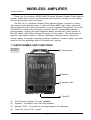
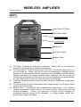
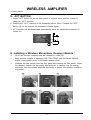
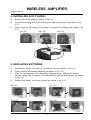
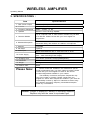
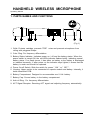
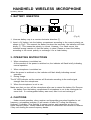
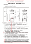
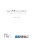
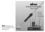
MA-705
Instruction Manual
ELECTRONICS CO., LTD.
Electronics Co., Ltd.
Head office: 814, Pei-Kang Road, Chiayi, 600, Taiwan.
Taipei office: 5, Lane 118, Sung-teh Road, Taipei, 110, Taiwan.
Web-http: //www.mipro.com.tw
E-mail: [email protected]
2CE196
WIRELESS AMPLIFIER
Operating Manual
Thank you for choosing a MIPRO MA-705 series Wireless Portable Public Address
System. Please take time to read these instructions carefully so that you can achieve
the best performance from the system.
The MA-705 is a Wireless Portable Public Address System, housed in a heavy
duty, ergonomically designed case. It offers 50 Watts (RMS) high fidelity output and
may be optioned with a wired microphone, up to two wireless microphones, and a CD.
The MA705 is conveniently powered by both AC and DC (rechargeable batteries)
power supplies. Applying the most advanced design techniques to each function of
MA-705 makes it the hottest wireless PA system on the market. The combination of
powerful, high fidelity sound in a flexible, lightweight package makes it perfect for
schools, places of worship, corporate meetings, exhibitions, aerobic classes, and other
small to mid size gatherings where PA systems are required.
1. PARTS NAMES AND FUNCTIONS
Front:
1
Fixed Handle
2
Speaker
3
Speaker Grille
4
Tripod Pit
(1)
Fixed Carrying Handle: For easy portability.
(2)
Speaker : A powerful 8-inch full-range speaker.
(3)
Speaker Grille : To protect the full-range speaker from damage.
(4)
Tripod Pit: Suits a 35ψ tripod.
-1-
WIRELESS AMPLIFIER
Operating Manual
Back:
5
Anti-Shock CD Player
6
DC Power Switch
B. Receiver Modules
A. Control Panel
(5)
(6)
(7)
(8)
(9)
7
Heat Sink
8
AC Input Socket
9
Battery Cover
CD Player: Featuring an anti-shock mechanism. Please refer to the instruction
manual for CD player that is included in the package.
DC Power Switch: Turns DC power on/off of the unit. The indicator glows when you
turn the power on. Please note that to avoid over-discharging or stressing built-in
batteries, it is recommended that you charge the unit immediately the LED indicator
flashes (indicating a low battery warning status). Otherwise, the unit will turn off
automatically at a preset, low DC power limit. Normal charging time is approximately
six hours and a built in protection circuit will prevent over-charging.
Heat Sink: Designed specially to cool the built-in amplifier, please keep it adequately
ventilated.
AC Input Socket: A built-in switch-mode power supply accepts for AC power inputs
ranging from 100V to 240V.
Battery Cover : To protect the built-in batteries and power supply. If you need to
change the batteries, please observe the correct polarity and always keep the
battery full-charged.
Unless you experience a battery failure, changing or
uninstalling batteries should not be necessary. If in doubt, please contact your
nearest service agent or supplier.
-2-
WIRELESS AMPLIFIER
Operating Manual
A. Control Panel
A9
A1
A2
A3
A4
A5
A6
A7
A8
(Fig.1)
(A1) Tone Control : Turn counterclockwise to increase bass or turn clockwise to
increase treble. Set at 12 o'clock for a flat response.
(A2) Master Volume Control : Simultaneously adjusts the volume of all mixed audio
inputs.
(A3) LINE IN Volume Control: Controls the volume of the Line Socket (A6).
(A4) Mic In Volume Control : Control the volume of the wired microphone (A7).
(A5) Line Out Socket : Stereo line level audio output.
(A6) Line In Socket : Allows you use an external device with an unbalanced audio
output as an input to the MA-705.
(A7) Wired Microphone Input Socket (XLR Balanced/Phone Jack Unbalanced) : Allows
you to connect a wired microphone with either a balanced XLR or unbalanced
phone jack connector.
(A8) Extension Speaker Socket : Connects to an 8 Ohm/50W speaker.
(A9) Charging Indicator: The charging indicator flashes when the system is charging.
Flashing stops when the batteries are fully charged.
B. Operating a Wireless Microphone Receiver Module
B5
B6
B7
CHANNEL NOISE
B8
RF
SCAN
ACT
SENSITIVITY
AF
VOLUME
B4
B3
B2
B1
(B1) Receiver Power Switch/Volume Control : Turns on/off of receiver module. After
power on, AF LED will flash. Turns knob clockwise to turn up volume.
(B2) Audio Signal Level Indicator: Indicate the audio signal level.
(B3) Sensitivity Adjuster: To adjust receiver sensitivity that ensures no noise output if
receiver is not receiving signals from transmitters.
(B4) ACT Button: To setup microphone frequency to match receiver frequency.
-3-
WIRELESS AMPLIFIER
Operating Manual
(B5) Scan Button: Press once to select receiving channel and autoscan the whole
bandwidth to avoid interference channel.
(B6) Channel Indicator: To display system's receiving channel.
(B7) Noise Indicator: To display if the system is under interference.
(B8) RF Signal Level Indicator: Indicate the RF signal strength received.
C. SWITCHABLE CHANNELS FUNCTIONS
1. Functions:
(a) This system incorporates advanced PLL synthesized oscillator design.
Preprogrammed with 16 switchable frequencies. Allow the user to freely select
any of the preprogrammed frequencies.
2. How To Select a Frequency:
(a) Auto Scanning Frequency Set-up: Holding down the SCAN button (B5) for 1
second. Release the button when numeric LED (B6) flashes. It will flash a total
of 6 times. To activate the AutoScan function, press the SCAN button once
within these 6 times. An open frequency will automatically be scanned and
saved/locked. *Note AutoScan function works only during numeric LED
flashing and within 6 times.
a) Pressandhold"SCAN"button
for1second.
CHANNEL NOISE
c) Press"SCAN" b uttonagainandrelease
LEDdisplayflashes.
b)
CHANNEL NOISE
RF
willautoscanforanopenfrequency.
RF
CHANNEL NOISE
SCAN
SCAN
ACT
+
SENSITIVITY
VOLUME
ACT
CHANNEL NOISE
SCAN
AF
+
SENSITIVITY
VOLUME
ACT
RF
SCAN
AF
d) Whendoneitwillautosaved/locked.
RF
+
SENSITIVITY
+
AF
VOLUME
ACT
SENSITIVITY
AF
VOLUME
(b) Manual Frequency Set-up: Holding down the SCAN button (B5) for 1 second.
Release the button when numeric LED (B6) flashes. It will flash a total of 6
times. To select any of the 16 frequencies in orderly format, press the SCAN
button and hold until the desired frequency is selected. This frequency will
automatically be saved/locked.
a) Pressandhold"SCAN"button
for1second.
CHANNEL
NOISE
RF
CHANNEL NOISE
SCAN
CHANNEL NOISE
RF
-
+
SENSITIVITY
AF
VOLUME
ACT
RF
CHANNEL
SCAN
SCAN
ACT
c) Press"SCAN"buttonandhold,
d) Whendoneitwillautosaved/locked.
frequencywillchangeeverytwoflashes.
LEDdisplayflashes.
b)
-
+
SENSITIVITY
AF
VOLUME
ACT
NOISE
RF
SCAN
-
+
SENSITIVITY
AF
VOLUME
ACT
+
SENSITIVITY
AF
VOLUME
3. Change channel when:
(a) Existing channel is being interfered or channel is malfunction.
(b) Select channel for multiple non-interference usage.
4. Caution while changing channels:
(a) When multiple channels are utilized do not change channel to avoid exiting
channel interference.
(b) When numeric knob reaches "_" it indicates an empty channel. Proceed until
a numeric number appears.
-4-
WIRELESS AMPLIFIER
Operating Manual
D. ACT BUTTON
1. Press "ACT" button (3) on the front panel of receiver once and the system is
ready for "ACT" function.
2. Position the "ACT" marking of the transmitter about 30cm. Towards the "ACT"
button (3) on the receiver as illustrated in below figure.
3. ACT function will be deactivated automatically once the transmitter frequency is
locked on.
ACT
E. Installing a Wireless Microphone Receiver Module :
1.
Up to two receiver modules may be installed in a MA-705.
2.
Each receiver module is equipped with "PILOTONE" and the latest "NOISE
LOCK" dual-squelch circuit to eliminate random noise.
3.
Unscrew the two screws from the filler panel and remove the filler panel. Insert
the receiver module into the empty slot and push it carefully into it's mating
connector. Use the screws removed previously to secure the receiver module in
to position.
A
B
C
D
E
F
-5-
WIRELESS AMPLIFIER
Operating Manual
2. INSTALLING ACD PLAYER :
A.
Remove the cover plate (as shown in fig. 3-1)
B.
Connect the linking wire to the CD player's connecting socket (as shown in fig.
3-2)
C.
Gently push the CD player in to position and tighten accordingly (as shown in fig.
3-3)
(fig. 3-1)
(fig. 3-2)
(fig. 3-3)
3. REPLACING BATTERIES
A.
Remove the screws and take off the battery cover (as shown in fig. 2-1)
B.
Gently remove the existing batteries (as shown in fig. 2-2)
C.
Slide the new batteries in to the battery compartment by aligning the battery
springs, taking care to ensure the correct polarity and terminal contact (as shown
in fig. 2-3)
D.
Replace the battery cover and screws (as shown in fig. 2-4)
(fig. 2-1)
(fig. 2-2)
(fig. 2-3)
(fig. 2-4)
-6-
WIRELESS AMPLIFIER
Operating Manual
4. HELPFUL TIPS :
1.
Please make sure the inbuilt rechargeable batteries are fully charged before and
after use. A characteristic of rechargeable batteries is that they will selfdischarging gradually over a period of time. Therefore, if the system will not be
used for a long period of time, please make sure the batteries are fully charged
before storing the MA-705. Warranty DOES NOT apply to over-discharged
batteries, hence, please ensure the batteries are recharged every 3 months.
2.
If you are operating the system from internal DC battery supply, you can expect
up to 5 hours of continuous use from a full charge on well conditioned batteries.
If you choose to operate the system from an external AC power supply, then the
internal battery supply will be charged at the same time.
3.
If the LED indicator on the power switch flashes after turning the unit ON, or
during use from the internal DC supply, you should switch to an AC power
supply immediately by using the AC power cord.
4.
Before turning the unit ON, please set all volume controls to their minimum level.
This prevents any loud "thumps" at power on. Adjust the volume controls only
after the unit is fully powered up.
5.
All audio sources can be amplified simultaneously while output volume of each
audio source can be controlled separately.
6.
During use, you may use the line level audio output to make a recording
7.
Please refer to the operating instructions for the wireless microphone for more
details on its use.
8.
MA-705 combines both a high efficient speaker and a super cardioid wireless
microphone for a clear and powerful output. So, NEVER place a microphone
right in front of speaker otherwise damaging feedback could occur (both to
operators ears and the system!).
9.
The extension speaker of MA-705 is rated at 50 watts @ 8 ohms. DO NOT short
out the speaker cables, otherwise, unwarranted damage could be done to the
system amplifier.
10.
To ensure optimal performance, the MA-705 can be installed on a stand or
placed on a platform, while microphones should be located beside or behind the
system to avoid feedback.
11.
Charging time for MA-705 is 4 hours. To ensure a long battery life, please
remove AC power plug after the system is fully charged.
12.
A rechargeable battery is an expendable item. Under normal operation, MIPRO
offers one year limited warranty.
13.
If you experience a short operating time when you know that the batteries are
fully charged, it is often a sign of aging batteries. Both rechargeable batteries
must be replaced (as a pair) at your earliest convenience.
-7-
WIRELESS AMPLIFIER
Operating Manual
5. SPECIFICATIONS :
Specifications
Item
1. Max. Power Output
50 Watts (RMS) in to a 8Ω Load
2. T. H. D.
< 0.1 %
3. Frequency Response
50Hz ~ 18 Khz ± 3 dB
4. Speaker
Built-in 8 Inch Full-range Speaker.
5. Receiver Module
Up to 2 optional UHF or VHF receiver modules may be fitted
to a MA-705. Please consult with your local supplier for
frequencies
6. Wireless Microphone
Suitable to use with MIPRO's hand held transmitter, or bodypack
transmitter fitting with lavaliere or headworn microphones
7. Antenna
Integrated
8. CD Player
Optional
9. Audio Input
Balanced/Unbalanced Mic In Jacks and Line In Jacks.
10. Power Supply
Built-in two 12 Volt 2.7 A Rechargeable Batteries and
90V ~ 264V Switching Power Supply.
11. Charging Time
Four Hours (Automatic Charging Management)
12. Dimension
400×285×225mm
13. Weight
8.8 Kg
14. Exterior Color
Black
Please Note:
Not all models are available in all markets and specific
model configurations may vary from market to market. Please
consult with your local supplier for detail of the various
models/configurations available in your market.
The suitability of wireless microphone frequencies may
vary from location to location. Please consult with your
supplier for advice about frequencies suitable in your area. No
responsibility is taken by Mipro for interference caused to/by
any wireless microphone frequency transmission/reception
under any circumstance.
Caution: Danger of explosion if battery is incorrectly replaced.
Replace only with the same or equivalent type.
-8-
HANDHELD WIRELESS MICROPHONE
Operating Manual
1. PARTS NAMES AND FUNCTIONS
1
2
3 4
5
6
7
8
9
(Fig.1)
1. Grille: Protects cartridge, prevents "POP" noise and prevents microphone from
rolling with polygonal shape.
2. Color Ring: For frequency differentiation.
3. Battery Status Indicator: Indicates power on / off and the battery status. When the
power switch is turned ON, the red LEDs indicator flashes briefly, indicating normal
battery status. If no flash occurs, it has either no battery or the battery is discharged
or installed incorrectly. If after power on the indicator stays lighted, it warns that the
battery is weak and should be replaced.
4. Power On-off Switch: Slide the switch for power " ON " or " OFF ".
5. Housing: Upper portion to be connected to capsule module and battery. Internally, it
holds transmitter PCB.
6. Battery Compartment: Designed to accommodate one 9 Volt battery.
7. Battery Cap: Covers battery in the battery compartment.
8. Anti-roll Ring: For frequency differentiation.
9. ACT Signal Receptor: Receiving ACT signal and adjusting frequency automatically.
-9-
HANDHELD WIRELESS MICROPHONE
Operating Manual
2. BATTERY INSERTION
(Fig.2)
1. Unscrew battery cap in a counter-clockwise direction (7).
2. Insert a 9V battery into the battery compartment according to the correct polarity as
shown in Fig.2. The moment the battery touches the terminals, the indicator will flash
briefly (7). This means the polarity is correct. However, if no flash occurs, this
indicates wrong insertion or that the battery is dead. Please re-insert the battery
according to its correct polarity or exchange it for a fresh battery.
3. OPERATING INSTRUCTIONS
1. When microphone is switched on:
At the moment of the power is switched on, the indicator will flash briefly indicating
normal operation.
1. When microphone is switched on:
When the power is switched on, the indicator will flash briefly indicating normal
operation.
2. During Usage:
The AF LED indicator on the receiver will illuminate according to the audio signal
strength from the microphone.
3. When the microphone is not in use:
Make sure that you turn off the microphone after use to extend the battery life. Remove
the battery from the battery compartment if microphone is not to be used again for
some time. If a rechargeable battery was used, take it out and recharge it.
4. CAUTIONS
Under normal operation, when receiver and transmitter are paired together to set
frequency, microphone indicator (3) will remain off after ACT setup the frequency.
However, if indicator (3) is flashing, it means receiver and transmitter are not in the
same frequency band. Please check the stickers on transmitter and receiver to observe
if they are sharing the same frequency bands.
- 10 -
BODYPACK TRANSMITTER
Operating Manual
1. PARTS NAMES AND FUNCTIONS
1
2
3
4
5
6
7
8
10
9
ACT
(Fig. 1)
1. AF Input Jack: Connects to either lavaliere or headset microphone. (See 5 ways of
connection on AF Input Connections)
2. Power Switch: Switch to ON position for operation. Switch to OFF position when not
in use.
3. Battery Status Indicator: Indicates the power on / off and battery status.
(a) When power switch is turned on: The LED indicator flashes briefly, indicating
normal battery status.
(b) When RED light illuminates at either power on or during usage: The battery level
is low, therefore, a new battery replacement is thus necessary.
4. Transmitting Antenna: 1/ 4 λ transmitting antenna.
5. Transmitter Housing: Packages the PCB and battery.
6. ACT Signal Receptor: Receiving ACT signal and adjusting frequency automatically.
7. Gain Control: Adjusts the desirous input gain.
8. GT/MT Level Select Switch: Switch GT position for electric guitar usage and "Line
In". Gain Control is irrelevant for "GT". Switch to "MT" for condenser microphone
or wired microphone. Gain Control works in "MT" for input sensitivity adjusting.
- 11 -
BODYPACK TRANSMITTER
Operating Manual
9. Battery Compartment and Cover: Accommodates one 9 Volt battery.
10.Detachable Belt Clip: Allows 360 degrees rotating to suit transmitting angles. To
detach simply use a screwdriver at a 45 degree angle to unfasten. see diagram.
2. OPERATING INSTRUCTIONS
1. To adjust GT/MT Switch (8), and Gain Control (7), simply push down both snap
locks on the sides of battery cover and flip it backwards to expose the adjustment
panel.
2. Before power on, ascertain if same channel was set up for both receiver and
microphone. If not adjust to same channel accordingly.
3. The LED indicator flashes briefly when power on indicating normal battery status. If
no flash occurs it has either no battery, the battery is drained or installed incorrectly.
Change accordingly.
4. Plug the microphone connector into the input jack (1) and tighten the connector
screw by clockwise direction as shown in (Fig. 2).
CapsuleConnector
Pleaseaim of t h e
fillister
andinsert the
connector
Headset
Lavalier
4
1
3
2
(Fig.2)
- 12 -
BODYPACK TRANSMITTER
Operating Manual
3. AF 4-PIN INPUT CONNECTION METHOD
(1) 2-Wire Electret Condenser Microphone Capsule
PIN
1
SHIELD
AUDIO
2
4
1
3
2
3
4
(2) 3-Wire Electret Condenser Microphone Capsule
SHIELD
PIN
1
2
AUDIO
4
1
3
BIAS
3
2
4
(3) Dynamic Microphone
2
1
SHIELD PIN
1
3
2
AUDIO
4
1
3
3
2
4
(4) Electric Guitar
SHIELD
PIN
1
2
AUDIO
4
3
1
2
3
4
(5) Line-in (Impedance 8KΩ ATT. 10dB)
SHIELD
AUDIO
PIN
1
2
4
1
3
3
2
4
- 13 -
BODYPACK TRANSMITTER
Operating Manual
4. BATTERY INSTALLATION
1. Pushing down both snap-locks on the sides of battery cover to open battery cover.
(Fig. 3).
2. Insert a 9V battery into the battery compartment observing the correct polarity as
shown in Fig. 4). Then push up to close the battery compartment as shown in Fig.
4).
(Fig.3)
(Fig.4)
PS: When the microphone is not in use:
Make sure the power to the microphone is switched off. If the microphone will not
be used for some time, please remove the batteries from the battery compartment to
avoid battery leakage and damaged battery springs and circuitry.
-14 -