1
1'Se'arsl
i
i i
iii
owners
manual
MODEL NO.
113.243401
SAW ON LY
MODEL NO.
113.243411
SAW WITH LEGS
AND MOTOR
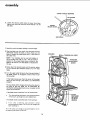
Serial
Number
Mode{ and serial
number may be found
at the right-hand
of the frame.
side
You should record both
model and serial number
in a safe place for
future use.
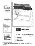
12-INCH BAND SAW/
SANDER
CAUTION:
Read GENERAL and
ADDITIONAL
SAFETY
INSTRUCTIONS
• assembly
carefully
Sold
PartNo. 69098
by
• operating
SEARS,
ROEBUCK
• repair
parts
AND
Chicago,
CO.,
IL.
60684
U.S.A.
Printed In U.S.A.
i
FULL ONE YEAR WARRANTY
If within one year from the date of purchase, this
workmanship,
Sears will repair it, free of charge.
WARRANTY
OR SERVICE
SERVICE
CENTER
IS AVAILABLE
THROUGHOUT
This warranty
state.
gives you specific legal rights,
SEARS,
general
ROEBUCK
AND
ON CRAFTSMAN
Craftsman
BY SIMPLY
THE UNITED
and you
CO., Sears Tower,
13,
4. REMOVE
ADJUSTING
Cluttered
must not
6. AVOID
areas
and
and align-
17. AVOID
Floor
Make
in.
ENVIRONMENT
All visitors should
8. MAKE WORKSHOP
-- with
keys.
9. DON'T
padlocks,
19. NEVER STAND
from work area.
or by removing
starter
10. USE RIGHT
better
at the rate for which
or attachment
to do a job
it was not
11. WEAR PROPER APPAREL
Do not wear loose clothing, gloves, neckties or jewelry
(rings, wristwatches)
to get caught
in moving
parts.
NONSLIP
footwear
is recommended.
Wear protective
hair covering
to contain
long hair. Roll long sleeves
above the elbow.
12. USE SAFETY
GOGGLES
21. DIRECTION
are NOT
safety
(Head Protection)
glasses."
Also,
plugging
ACCESSORI ES
is tipped
or if the
PARTS
OF FEED
Feed work into a blade or cutter against
rotation of the blade or cutter only.
the direction
of
22. NEVER LEAVE TOOL RUNNING
UNATTENDED
Wear safety goggles (must comply with ANSI Z87.1 ) at all
times.
"Everyday
eyeglasses
only have impact resistant
lenses, they
before
Before further
use of the tool, a guard or other part that
is damaged should be carefully checked to ensure that it
will operate properly and perform its intended function.
Check for alignment of moving parts, binding of moving
parts, breakage of parts, mounting,
and any other conditions that may affect its operation.
A guard or other
part that is damaged should be properly
repaired or
re placed.
TOOL
Don't
force tool
designed for.
position
ON TOOL
20. CHECK DAMAGED
and safer
as
Do not store materials
above or near the tool such that
it is necessary to stand on the tool to reach them.
FORCE TOOL
It will do the job
it was designed.
such
STARTING
is in "OFF"
Serious injury could occur if the tool
cutting tool is accidentally
contacted.
KID-PROOF
master switches,
ACCI DENTAL
sure switch
accessories
Consult the owner's manual for recommended
accessories.
Follow the instructions
that accompany
the accessories.
The use of improper accessories may cause hazards.
AWAY
be kept a safe distance
changing
18. USE R ECOMMENDED
Don't use power tools in damp or wet locations or expose them to rain. Keep work area well lighted, Provide
adequate surrounding work space.
7. KEEP CHILDREN
CARE
TOOLS
before
servicing;
when
blades, bits, cutters, etc.
be slippery due to wax or sawdust.
DANGEROUS
TOOLS WITH
16. DISCONNECT
CLEAN
accidents.
and balance at all times.
Keep tools sharp and clean for best and safest perform.'
ance. Follow
instructions
for lubricating
and changing
accessor ies.
KEYS AND WRENCHES
invite
tools
SECURE WORK
15. MAINTAIN
benches
vary from state to
IL 60684
Keep proper footing
Form habit of checking to see that keys and adjusting
wrenches are removed from tool before turning it on.
5. KEEP WORK AREA
STORE
14. DON'T OVERR EACH
IN PLACE
and in prGper adjustment
or
Use clamDs or a vise to hold work when practical. It's
safer than using your hand, frees both hands to operate
tool.
This tool
is equipped
with an approved
3.conductor
cord and a 3-prong grounding type plug to fit the proper
grounding type receptacle.
The green conductor
in the
cord is the grounding wire. Never connect the green wire
to a live terminal.
order,
SEARS
rights which
Chicago,
in material
mask if cutting operation is dusty, and ear protectors
(plugs or n_uffs) during extended periods of operation.
ALL TOOLS
-- in working
ment.
BSC 41-3,
NEAREST
for power
POWER TOOL
3. KEEP GUARDS
THE
may also have other
Read the owner's manual carefully.
Learn its application
and limitations
as well as the specific potential
hazards
peculiar to this tool.
2. GROUND
Band Saw fails due to a defect
CONTACTING
STATES.
safety instructions
1. KNOW YOUR
BAND SAW
Turn power
off.
complete stop.
use face or dust
2
Don't
leave
tool
until
it comes
to
a
additional safety instructions for band saw/sander
Safety
is a combination
of
alertness
at all times when
to keep blade breakage to a minimum,
maximum
support
for blade.
operator
common
sense and
the band saw is being used.
When cutting
a large piece of material,
is supported
at table height.
h°
WARNING:
FOR YOUR OWN SAFETY,
DO NOT
ATTEMPT TO OPERATE YOUR BAND SAW UNTIL IT
IS COMPLETELY
ASSEMBLED
AND INSTALLED
ACCORDING TOTHE INSTRUCTIONS , .. AND UNTIL
YOU
HAVE
READ
AND
UNDERSTOOD
THE
FOLLOWING:
PAGE
1. General Safety Instructions for Power Tools
2. Getting To Know Your Band Saw/Sander
3. Basic Band Saw Operation
......
........
Hold
j.
Do
not
example
permitted
of Machine
11
cut
pieces
of material
too
small
to
hold
o.
by
P.
Avoid
could
awkward
hand positions
where a sudden slip
cause a hand to move into the blade or the
sanding belt.
d.
f.
q.
Never turn your band saw "ON"
before
table
of all Objects
(tools,
scraps of
except for the workpiece
devices for the operation
e°
and related
planned.
clearing the
wood,
etc.)
cutting.
the
blade
when
cutting
off
table
round
and
not
material
be
such
Turn
up the kerf.
off
the
If this happens:
band
saw . . . remove
plug
from
adjust
tension
correctly
belt being used...
for
Never leave the band saw work area with the power
on before the machine
has come to a complete
stop,
or without
removing
and storing the switch key.
Never operate
on the unused
the band saw with protective
cover on
shaft end of the motor removed.
Do not perform
layout,
assembly,
or setup
on the table while the cutting
tool is rotating.
Remove
plug
from
power,
before installing
or removing
ment.
work
and turn
saw "OFF"
an accessory or attach-
feed or support
Make sure the blade runs downward
toward the table
in the right direction.
Always
adjust tracking
wheel
correctly
so that the blade does not run off the
wheels.
Always
sanding
while
power
source
outlet
. . . remove
cover from
band saw. Insert a screwdriver
or wedge in the
kerf..,
rotate the wheels by hand while backing
up the workpiece.
n.
c.
fast
Eyes, Hands, Face, Ears, Body
Wear safety goggles that comply
with ANSI Z87.1 and
a face shield if operation
is dusty. Wear ear plugs or
muffs during extended
periods of operation.
Do not
wear gloves..,
roll long sleeves above the elbow.
Do not
hand.
too
When backing up the workpiece,
the blade may bind
in the kerf (cut) .,. this is usually caused by sawdust
m.
The band saw should be positioned
so neither the operator nor a casual observer is forced to stand in line with
the blade. This band saw is intended
for indoor use only.
b.
material
the table.
as dowel
rods, or tubing.
They have a tendency
to
roll
while being
cut causing
the blade to "bite".
Always
use a "V"
block,
or clamp round material
to a miter gauge.
6. Location
a.
the
against
should
lay flat
on the
to rock while being cut.
Use caution
22
clogging
7. Protection:
feed
firmly
sure it
Use caution
when
cutting
off
material
which
is
irregular in cross section which could pinch the blade
before the cut is completed.
A piece of molding
for
k°
2
Your band saw must be bolted securely to a stand or
work bench. In addition, if there is any tendency for the
band saw to tip over or move during certain operations
such as cutting long heavy boards, bolt your bandsaw to
the floor.
the work
make
Only feed the material
fast enough so that
will cut. Keep fingers away from the blade.
21
4. Maintenance ...............................
5. Stability
i.
18
....................
and to provide
the
blade
8. Should any part of this band saw be missing, or bend, or
fail in any way, or any electrical
component
fail to
perform
properly,
shut off power switch,
and remove
power
supply
cord
from
power
supply.
Replace
damaged,
missing,
and/or
failed parts before
resuming
operation.
or
g. Always adjust the upper blade guide and blade guard
to just clear the workpiece
to protect
the operator,
9. Think Safety.
Safety is a combination of operator common sense and
alertness whenever the band saw/sander is in operation.
additional safety instructions
for band saw/sander
WARNING:
THE 5" BAND SAW PULLEY AND THE
2-1/2" MOTOR PULLEY FURNISHED, WILL RUN THE
BLADE AT APPROXIMATELY
900 RPM (OR 2700
FEET PER MINUTE)WHEN
USED WITH A 1725 RPM
MOTOR. NEVER SUBSTITUTE THESE PULLEYS TO
INCREASE THIS SPEED BECAUSE IT COULD BE DANGEROUS.
WEAR
WARNING:
DO NOT ALLOW FAMILIARITY
(GAINED
FROM FREQUENT
USE OF YOUR BAND SAW) TO
BECOME COMMONPLACE. ALWAYS REMEMBER THAT
A CARELESS FRACTION OF A SECOND IS SUFFICIENT TO INFLICT SEVERE INJURY.
YOUR
"['he operation
of any power
tool can result in foreign
objects
being thrown
into the eyes, which
can result in
severe eye damage. Always
wear safety goggles complying
with ANSI Z87.1
(shown on Package) before commencing
power tool operation.
Safety Goggles are available at Sears
retail or catalog stores.
READ AND FOLLOW THE INSTRUCTIONS
THE FRONT OF THE BAND SAW/SANDER.
APPEARING
ON THE INSTRUCTION
4
ALWAYS
CLEARS
ADJUST
UPPER
WORKPIECE
PLATE ON
GUIDE
SO THAT
IT JUST
S MINff_E
INJURY POTENTIAL
OF CONTACT
WITH
SAW BLADE OR SANDING
SELT BY KEEPtNG
6
12
INCH
i
f
f
FINGERS
MAINTAIN
A SAFE DISTANCE
AWAY
CONTROL
OF THE WORKPfECE
AT
HITTff_GEND OF SLOT _NINSERT. OR JAMMING
SLOT
BAND
SAW-
SANDER
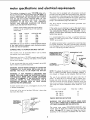
motor specifications and electrical requirements
This machine is designed to use a 1725 RPM motor only.
Do not use any motor that runs faster than 1725 RPM. It is
wired for operation on 110-120 volts, 60 Hz., alternating
current. (TOOL MUST NOT BE CONVERTED TO OPERATE ON 230 VOLT EVEN THOUGH SOME OF THE
RECOMMENDED
MOTORS
ARE DUAL
VOLTAGE.
CHANGING
TO 230 VOLT WILL
NOT CONSERVE
ENERGY
AND REQUIRES
CHANGING
THE POWER
CORD PLUG AND MOTOR RECEPTACLE.
THESE
CRAFTSMAN
MOTORS
FOUND
TO BE ACCEPTABLE
THIS TOOL.
HP
1/2
1/2
1/2
1/2
3/4
RPM
1725
1725
1725
1725
1725
HAVE BEEN
FOR USE ON
TO POWER SOURCE
This machine
must be grounded
the operator
from electric shock.
while
a mating
If the outlet
you are planning
of the two prong type
DO
THE GROUNDING
PRONG
3-conductor
connect
protect
is properly
grounded,
WARNING:
IF NOT PROPERLY GROUNDED
THIS
POWER TOOL CAN CAUSE AN ELECTRICAL SHOCK
PARTICULARLY
WHEN USED IN DAMP LOCATIONS
CLOSE TO PLUMBING. IF AN ELECTRICAL
SHOCK
OCCURS
THERE
IS THE
POTENTIAL
OF A
SECONDARY
HAZARD
SUCH AS YOUR HANDS
CONTACTING THE SAW BLADE.
or cut,
or damaged
such as to a properly
grounded
outlet
MAKE SURE THIS IS
CONNECTED TO A
H
box.
GROUNDING
in any way, have
less than
150volts
ADAPTER
2-PRONG
RECEPTACLE--
------_
NOTE:
The adapter illustrated
is for use only if you already
have a properly
grounded
2-prong
receptacle.
Adapter
is
not allowed
in Canada
by the Canadian
Electrical
Code.
The use of any extension
cord will cause some loss of
power.
To keep this to a minimum
and to prevent
overheating
and motor burn-out,
use the table below to determine the minimum
wire size (A.W.G.)
extension
cord, Use
only 3 wire extension
cords which
type
plugs and 3-pole
receptacles
plug.
Cord
Length
PROPERLY
GROUNDED
have 3-prong grounding
which
accept the iools
Wire
Size
A.W.G.
it has a plug
Up to 100 Ft.
3-PRONG
PLUG
LUG
3--PRONG
PLUG
Extension
If your unit is for use on
that looks like below.
electrician
grounded
An adapter as shown below is available for connecting
plugs
to 2-prong
receptacles.
The green grounding
lug extending
from the adapter must be connected
to a permanent
ground
grounded
type
or Circuit-Saver
WARNING: DO NOT PERMIT FINGERSTO TOUCH THE
TERMINALS
OF PLUGS WHEN INSTALLING
OR REMOVING
THE PLUG TO OR FROM THE OUTLET.
If power cord is worn
it replaced immediately.
the grounding
you have a qualified
outlet
with a properly
KNOWN GROUN_:
If you are not sure that your outlet
have it check by a qualified
electrician.
type
OUTLET
in use to
Plug power cord into a 110-120V
properly
outlet
protected
by a 15-amp. time delay
fuse or circuit
breaker.
grounded
to use for this power tool is
NOT REMOVE
OR ALTER
IN ANY
MANNER.
Use an
and always
It is recommended
that
replace the TWO prong
THREE
prong outlet.
CAUTION: Do not use blower or washing machine motors
or any motor with an automatic reset overload protector
as their use may be hazardous.
CONNECTING
This plug requires
outlet as shown.
adapter as shown below
lug to known ground.
CATALOG NO.
1254
1278
1255
1279
1256
VOLTS
115
115
115
115
115
This power tool is equipped
with a 3-conductor
cord and
grounding
type plug which has a grounding
prong, approved
by Underwriters'
Laboratories
and the Canadian
Standards
Association.
The ground conductor
has a green jacket and
is attached to the tool housing at one end and to the ground
prong in the attachment
plug at the other end.
CHECK
16
100-200
Ft.
14
200-400
Ft.
10
MOTOR
ROTATION
WARNING:
FOR YOUR OWN SAFETY, MAKE SURE
PLUG IS NOT CONNECTED TO POWER SOURCE OUTLET. WHEN CHANGING MOTOR ROTATION.
OUTLET_
GROUNDING
PRONG
The
motor
viewed
from
must
rotate
COUNTERCLOCKWISE
the shaft end to which you will
mount
when
the
pulley.
,(See page 10) if it does not, change the direction
according
to the instructions
furnished
with
the motor.
unpacking and checking contents
CONTENTS
UNPACKING
ASSEMBLY
Installing
AND CHECKING
Sawdust
Assembling
Elbow
Steel
Installing
Legs
Table
Pulley
Belt
Check
Motor
Rotation
Mounting
Motor
Attaching
Belt
The
Adjusting
On-Off
Guard
8
and
Motor
10
10
..................
11
16
.......................
16
YOUR
BAND
........................
Diagrams
Scales
18
..................
Knob
18
...............
18
.......................
18
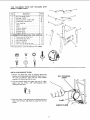
TOOLS
SCREWDRIVER
NEEDED
COMBINATION
7/16
SCREWDRIVER
COMBINATION
SQUARE
INCH
WRENCH
3/4 INCH
WRENCH
SQUARE
MUST
RE
LIGHT
A
H
/
EDGE
OF
BOARD
3/4"
THICK
THIS EDGE
MUST
BE
PERFECTLY
BE NQ
GAP
IS FLIPPED
OR
OVER
STRAIGHT
certain all items
packing material.
A
IN
HERE
DOTTED
WHEN
POSITION,
are accounted
for,
before
discarding
any
If any parts are missing, do not attempt
to assemble the
band saw, plug in the power cord or turn the switch
on
until the missing parts are obtained
and installed correctly.
ITEM
OVERLAP
Band Saw/Sander
is shipped complete
DOES NOT INCLUDE
Steel Legs or
Separate all parts from packing
materials
and check each
item with
illustration
and "Table
of Loose Parts."
Make
/
SF!OULD
18
18
18
18
18
19
19
21
21
21
22
22
22
22
22
22
23
23
Model 113.243411 Band Saw/Sander is shipped complete
in one carton and INCLUDES Steel Legs and Motor.
TRUE
ON BOARD
THIS EDGE
SQUARE
Model 113.243401
in one carton
but
Motor.
lJ _r_
WRENCH
3/8 INCH
STRAIGHT
DRAW
9
..................
12
Tension
LINE
ALONG
.
...................
Adjustment
MEDIUM
Installation
Table
Tension
SMALL
8
...................
SAW/SANDER
Table Tilting ........................
Blade Guide Adjustment ................
Lateral Guide Adjustment ...............
Blade Thrust Bearing Adjustment ..........
Guide Bar Lock Screw ..................
Guide Bar ..........................
Installing Sanding Attachment ............
BASIC BAND SAW/SANDER OPERATION
.....
Sawing ............................
Sanding ...........................
MAINTENANCE
.......................
Tires .............................
General ............................
Motor .............................
Lubrication .........................
Recommended Accessories ...............
TROUBLE SHOOTING ...................
REPAIR PARTS .......................
7
Blade
KNOW
Adjustment
................
......................
Switch
TO
6
..................
Buards
The
GETTING
....
......................
Motor
Installing
CONTENTS
B
C
D
E
F
G
H
J
TABLE
OF LOOSE
PARTS
QTY.
Basic Saw Assembly
.....................
1
Owner's Manual
........................
1
Saw Table
.............................
1
1/2 x 52-1 n. V-Belt
......................
1
Carton containing Belt Guard, Belt-Guard
Support,
Support Bracket, three Clips and three Self2
"rappi ng Screws ........................
1
1/2-1n. Sanding Belt
.....................
1
1/4-In.
Band Saw Blade
1
Sawdust Elbow
.........................
Two Bags containing
the following
items:
1
Set Screw Wrench, 1/8"
1
Set Screw Wrench, 5/32"
. ...............
1
Set Screw Wrench, 3/16"
1
Flat Washer, 1-1/8" diameter
.............
Trunnion
Locknut
1
2
Pan Hd. Mach. Screw, Self Tap, 10-32 x 3/8"
2
Pan Hd. Math. Screw, Self Tap, 8-32 x 3/8"
.
1
Soc. Hd. Setscrew, Flat Pt., 5/16-18
x 3/8"
.
1
Flat Hd. Mach. Screw, 6-32 x 7/!6"
. .......
1
Hex Nut, 6-32 .........................
1
Split Lockwasher,
No. 6 .................
Tilt Pointer
1
1
Tube Clamp
..........................
1
Rubber Gasket (strip)
...................
1
Alignment
Plate
.......................
1
Motor Pulley, 2-1/2"
. ..................
1
Sanding Platen
........................
1
Cord Clamp
..........................
Table Insert
..........................
1
1
Tilt Lock Handle (Wrench)
...............
1
Spacer ...............................
1
Blade Tension Knob
....................
2
Switch
Key ...........................
1
Flat Washer, 9/32 x 5J8 x 1/16 ............
1
Screw Truss Hal., 1/4-20 x 1 ..............
Wing Nu_, lj4-20
......................
= 1
THE
FOLLOWING
PARTS
MODEL 113.243411 ONLY.
I tern
A
A
B
C
D
E
F
G
H
J
K
INCLUDED
*Nut,
Hex Head 1/2-13
Qty.
...........
* Nut Hex 1/4-20
*Screw Truss Hd.
...............
1/4-20 x 5/8
* Lockwasher,
External
* Foot,
Motor
1/4
WITH
jJ
Description
8
......
........
32
32
32
Leveling
................
......................
Leg .......................
Channel, Support
4
1
4
2
..............
Stiffener,
Side
................
2
Stiffener,
End
...................
2
Support,
Motor
HARDWARE
L
C
A
M
N
ARE
...............
FOR MOUNTING
1
*Screw, Hex Hd. 5/16-18 x 1 ........
* Lockwasher Ext. 5/16 ...........
*Nut, Hex 5/16-18 ..............
*Washer 11/32 ID ..............
*Bolt, Carriage 5/16-18x 3/4 .......
* Parts Contained
In Loose Parts Bag Part No.
A
l
TOOL & MOTOR
B
4
8
8
8
4
K
69097
C
D
k
M
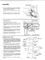
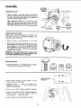
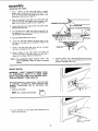
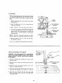
INSTALLING
1. Remove
N
SAWDUST ELBOW
the
Band
Saw
pressure on the spring
the cover by pulling
procedure
for bottom
cover
by
applying
gentle
side
tabs and release the top portion
of
it away from the frame. Repeat
portion
of cover.
SELF-THREADING
SCREW
2. Find the sawdust elbow, the clamp, the strip of rubber
gasket, and two 10-32 x 3/8" self-threading
screws
among the loose parts.
3.
Place the elbow in the opening at the bottom
left-hand
side of saw as shown, and attach the clamp with the two
screws.
CLAMP
SAWDUST
E LBOW
assembly
RUBBER GASKET
4. Peel off the protective covering from the rubber gasket
and stick it around the clamp. Make sure it extends a
little beyond each end of the clamp.
The
out.
gasket will
help
to prevent
sawdust from
leaking
For the most efficient removal of sawdust, attach a
Craftsman Home-n-Shop Vac to the sawdust elbow.
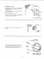
INSTALLING
TABLE TRUNNION
TABLE
Apply a coat of automobile wax to the table.
1. Place the table on the band saw so that the two
pins and the table
trunnion.
lock
bolt
go through
trunnion
the slot
in the
2. Find the 1-1/8" dia. flat washer, a sleeve 11/16" long,
the trunnion lock nut and the table lock handle from
among the loose parts.
3. Hold the head of the table lock bolt inside the band saw
with your left hand and put the 1-1/8" dia. flat washer,
the sleeve,and the handle on the bolt.
4. Screw the nut on the bolt and tighten it with the handle
while the table is in a horizontal position.
TABLE LOCK BOLT
ASSEMBLING
STEEL
TABLE LOCK HANDLE
LEGS
HEX NUT
1. Assemble the two (2) End Stiffeners and the two (2)
Side Stiffeners usingfour (4) 1/4-20 Truss head screws.
The End Stiffeners are placed on top of each Side
Stiffener as shown. Insert screws through the 9/32 inch
diameter holes and attach Iockwashers and 1/4-20 nuts
and finger tighten nuts.
2. Attach
the four
using 1/4-20
3.
Remove
(4) legs to the Side and End Stiffeners
screws, Iockwashers
the
four
(4)
Truss
screws which
were
assembled in Paragraph
No. One. Place the two (2)
Support Channels as shown, in position, align holes in
supports with holes in the Stiffeners, replace Iockwashers
and nuts. Tighten all nuts using 7/16" wrench.
SIDE
STIFFENER
_
CHANNEL
LOCKWASHE
I
,
I
SIDE STIFFENER
J
-_--_
_
I _-_:_t
R ___i
__,
._J
CHANNEL
SUPPORT
I'!'1_
SCREW -, '1
/
', /_
I, .l
./
_
[ }
LEGS/I'
SCREW
Assemble the motor support to steel legs with 1/4-20
screws and nuts. Motor
support
can be mounted
to
either
5.
END
__
/
4.
LOCKWASHER
_ _--
_
STIFFENER
SUPPORT
and nuts as shown.
head
SCREW
end of
stand. Tighten
nuts.
Install leveling feet as shown. To level Leg Set, loosen
nut on inside of leg and turn nut on outside to raise or
lower feet. Adjust all four levelers, if necessary, and then
tighten
/
l uT
su""°"
"--_.- U
I/
nuts on inside of leg.
I i
1\ \.OTOR
LOCKWASHER
!Ii,,
NOTE:
justment.
These
levelers
are not
intended
for
height
ad-
LEVELING
....
rcc.
_
__
LTj'\
_
e------_
\
1/2-B
HEX NUT
assembly
MOUNTING
BAND SAW/SANDER
ON FLOOR STAND
NOTE:
For illustrative
purposes, the Band Saw is shown
mounted
on the Craftsman Catalog No. 9-22:236 Steel Leg
Set. This Leg Set is included with Model No. 113.243411.
LEFT
FOOT
1. Remove
the
Band
Saw
pressure on the spring
of the cover by pulling
procedure
for bottom
NOTE: Check
Saw as shown.
cover
by
applying
gentle
tabs and release the top
it away from the frame.
portion
RIGHT
FOOT
side
portion
Repeat
of cover.
CHECK BOLTS
FOR
the bolts which hold the feet to the Band
Make sure they are tight.
o
O
O
O
O
2. Place the Band Saw on the Steel
and align the mounting
with those in the END
in the illustration).
Legs, position
as shown,
holes in the feet of the Band Saw
STIFFENERS
(marked with an X
;o0
0Oo
o O
©O
O
MOTOR
MOTOR PULLEY BELT GUARD AND MOTOR
INSTALLATION
MOUNTING
1. Place
facing
motor
on
your
with
THIS
END
the
shaft
you.
If you are using a double
shaft must be facing you.
2. A_ach
screws,
workbench
AT
THREAD CUTTING
SCREWS
BELT GUARD
the
SUPPORT
guard support
furnished
with
shaft
motor,
to the bracket
the guard.
the
5/8"
with
the
alia.
two
NOTE: The holes in the bracket are not threaded, but the
screws are "thread cutting screws" and will cut a thread as
they are tightened.
BELT
SUPPORT
GUARD
BRACKET
BELT GUARD
SUPPORT
assembly
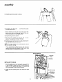
MOUNTING
SETSCREW
WRENCH
PULLEY
|
_
-
'
3/16x
3/16 KEY
1. Loosen setscrew in the motor pulley and place the
pulley on the shaft with the hub flush with the end of
the shaft. Insert the motor shaft key and tighten the
setscrew with 5/32" setscrewwrench.
\
When installing the pulley on a 1/2" diameter motor
shaft, make sure that the adapter sleeve and 3/16"
square key furnished with your motor are in place.
Then tighten the setscrewwith a 5/32" setscrew wrench.
MOTOR
SHAFT
KEY
FLUSH HERE
CHECK MOTOR ROTATION
NOTE: Motor supplied with Model No. 113.243411 only.
The motor must rotate COUNTERCLOCKWISE
when
viewed from the PULLEY end.
1. Place the motor on your workbench or on the floor.
2. Stand clear of the motor and plug the cord into a properly grounded outlet (See page 4). Notice the rotation
of the pulley. If it is not turning COUNTERCLOCKWISE, REMOVE the plug from the outlet, and change
the rotation of the motor according to the instructions
furnished with the motor.
WARNING:
FOR YOUR OWN SAFETY, MAKE SURE
PLUG IS NOT CONNECTED TO POWER SOURCE OUTLET WHEN CHANGING MOTOR ROTATION.
MOUNTING
MOTOR
I. Find four 5/16"-18 x 1" carriage bolts, flat washers,
lockwashers and nu_ supplied with the base.
L3
2. Insert the bolts through the holes marked "X"
behind the motor mount bracket.
MOTOR MOUNT
BRACKET
from
O
[]
[]
3. Attach the motor . . . place a flat washer and a
Iockwasher on each bolt . . . screw on the nuts but
DON'T TIGHTEN them.
4. Loosen the two BELT GUARD
SUPPORT SCREWS.
5. Loosen the two MOTOR BASE CLAMP SCREWS and
rotate the motor so that the ventilation holes are
facing downward..,
tighten the screws.
& Tighten the BELT GUARD
SUPPORT SCREWS.
I0
",
ADAPTER
SLEEVE
1/2 I_IA. MOTOR
SHAFT
RD SUPPORT
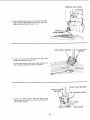
ATTACHING
BELTGUARDS
1. Remove the pulley from the band saw, using the 5/32"
setscrew wrench to loosen the screw. Be careful not to
lose the shaft key.
Attach
nished
NOTE:
the
with
belt guard support
the guard.
The support
bracket
with
the three screws
fur-
is not required.
The holes for attaching
the support
but
the screws are "self-threading"
thread
as they
are screwed
in.
are not threaded,
and will
cut
a
/
SELF-THREADING
"
2: Replace the
the shaft.
pulley
with
the
hub
flush
with
the end
FLUSH
LONG
three
clips
long tabs pointing
4.
Insert
guard
on the belt guard 90 ° apart
AWAY
from
the round
one looped end of the belt all
so that it will be below the motor
HERE
of
POINTED
3. install
SCREW
TAB
THiS
WAY
with the
opening.
the way
pulley.
into
the
o
_;_'-- _"
1'1
SPRi90NG
CLIPS
(SET
° APART)
assembly
5, Snap the guard into position as shown.
6. Look down into the guard . . . pull the belt upwards
onto the motor pulley.
7. Insert the belt into the open end of the second belt
guard, and out the round opening. Place the belt onto
the band saw pulley by rotating the pulley.
8. Snap the belt guard into position.
9. Move the motor sideways so that the belt is in the
center of the opening in the top of the base.
10. PUSH downward on the motor to apply tension to the
belt and tighten the motor bolt nuts.
NOTE: It is only necessary to tension the belt so that it
does not slip while running.
If you cannot obtain sufficient tension with the motor
pushed a!l the way down, remove the four motor bolts
and insert them in the LOWER set of holes.
TENSION
STUD
POINTER
INSTALLING
THE BLADE
1. Find the blade tension knob among the loose parts. Put
a dab of grease or_vaseline on the end of the knob and
screw it on the tension stud. Screw it on only a few
turns, just enough to start moving the pointer.
2. Loosen the two mounting screws and remove the blade
guard.
GUARD
MOUNTING
SCREWS
12
GUIDE
BAR LOCK
SCREW
GUIDE
3.
Loosen the guide
bar lock screw and position
guide assembly
approximately
three inches
table as shown and tighten the lock screw.
the upper
above the
UPPER
4.
Loosen
the two setscrews which
lock
guides and separate them about 1/8".
the
upper
Do that same thing
to the lower guides beneath
table. See Page 14 Step 6 for location
of setscrew.
THRUST
BEARING
I I II1/8"SETSCREW
blade
the
_'_ _ _--"
I
ADJ. KNOB
\
5.
Loosen
the
setscrew
which
bearing and turn the knob
the way back as shown.
until
locks
the
the thrust
BAR
upper
bearing
thrust
is all
13
/_
II
UPPER
THRUST
II /
i i]
_ [-_
/
/1/8"
_SCREWS
SETSCREW
/
BEARING
WRENCH
assembly
LOWER
THRUST
BEARING
SETSCREW
6. Loosen the setscrew which locks the lower thrust bearing and turn the knob until the thrust bearing is all the
way back.
LOWER
BLADE GUIDE
SETSCREW
7. Carefully uncoil the blade, holding it at arms length.
8, Place the blade over the wheels with the teeth pointing
downwards toward the table as shown. Make sure the
blade is between the blade guides and is in the center of
the rubber tires.
POINTER
--_---TENSION ADJ. KNOB
NOTE: Your bandsaw can be used with blades of
various widths from 1/8" to 1/2"'. The saw must be
adjusted to the proper blade tension setting for the
blade to be used. A 1/4" wide blade is included with
this saw.
TRACKING
SCREW
9. Screw down the tension knob until the pointer points
to 1/4. This will put sufficient tension on a 1/4" wide
blade.
10. Turn the upper wheel by hand a few times and notice if
the blade remains in the approx, center of the tire on
the top wheel.
If the blade moves away from the center of the wheel
while you are turning it, the blade is not TRACKING
properly.
The top wheel shaft is hinged which allows the wheel to
be tilted so that the blade can be TRACKED. By
turning the tracking adjustment screw, the wheel will be
tilted. (see illustration).
If the blade moves toward
a.
of the band saw:
BLADE
CENTERED
ON TIRES
OF BOTH
WHEELS
Turn the tracking adjustment screw clockwise about
1/4 of a turn, as though you were tightening it.
If the blade moves toward
a.
the front
the back of the band saw:
Turn
the
tracking
adjustment
screw
counterclockwise
about 1/4 of a turn as though you
were loosening it.
Turn the screw
the approximate
just enough to cause the blade to run in
center of the tire.
14
THRUST
The thrust bearings support the blade from the rear and
will rotate when the blade is pushed against them while
you
are cutting,
As soon as you stop cutting,
the
bearings
should
ADJ.
THRUST
BEARING
KNOB
BEARIN(
stop rotating.
11. To be sure the thrust bearing is properly supporting the
blade, turn the thrust bearing adjustment knob so that
the bearing moves toward the blade and almost touches
it.
12. While turning
the upper wheel
adjust the thrust
bearing
until
blade and starts to rotate. Now
slightly,
until
it
bearing setscrew.
stops
rotating.
to the right by hand,
it barely touches
the
move the bearing back
Tighten
the
thrust
13. Adjust the lower thrust bearing the same way.
NOTE: The upper and lower blade guides support the blade
and keep it from twisting
during operation.
An adjustment
is necessary when blades are changed or replaced,
G
14. To adjust the upper blade guides loosen the setscrew
which locks the blade guide holder (see illustration).
APPROX.
1/32"
BLADE
15. Turn the blade guide adjustment knob, so that the
guides move toward the blade. Move them until the
"ledge" is about 1/32" from the deepest part of the
blade teeth. This deep part is called a "gullet". Tighten
the setscrew.
16. Adjust
the lower
KNOB
SETSCREW
guides the same way.
BLADE
17. Press the two guides evenly
against the sides of the
blade, but don't pinch the blade. Release the guides and
rotate
the upper wheel a little
bit, moving the blade
downward.
Make sure one guide
is not farther
away
from the blade than the other. Tighten
both setscrews.
18. Adjust
the lower
Y__---U
21. Locate
table.
22. Replace
GUIDE
HOLDER
SAW
BLADE
PPER
BLADE
GUIDE
guides the same way.
19. Rotate the upper wheel a few times by hand, and check
the guides and thrust bearings. Make readjustments if
necessary.
20. Replace
GUIDE
ADJ.
the blade guard on the upper
I
guide support.
the table insert and place it in the opening
in the
TRUSS
HEAD SCREW
AND WlNGNUT
the cover.
15
assembly
ADJUSTING
THE TABLE
1.
Find a 1/4-20 x 1 inch truss head screw, a regular
washer, and a 1/4-20 wing nut among loose parts. Insert
the screw into the hole in the table top as shown in the
illustration at the bottom of page 15.
2.
From
wing
tight.
3.
4.
the underside
of the table,
screw the washer
and
nut onto the truss head screw and tighten
finger
This will keep the table fiat and in alignment.
Locate among the loose parts a 5/16"-18
head flat point setscrew.
This setscrew
acts as a 90 ° stop. Screw
x 3/8" socket
5/32"' SETSCREW WRENCH
it partially
into
the tapped hole in the top of the table on the left side.
Use the 5/32" setscrew wrench.
5.
Raise the blade guides all the way up.
6.
Loosen the table lock slightly and push down on the
left side of the table until it touches the frame of the
band saw.
7.
Screw in the stop screw and notice
the frame, the table will start to tilt.
8.
Place a square on the table against the blade and
continue
to screw in the stop screw until the table =s
square with the blade. Tighten the table lock.
"NOTE:
The
combination
start of "assembly"
method."
square
must
section
that
POINTE
as it touches
be "true"--
see
9.
on pg. 6 for checking
ON-OFF SWITCH
WARNING:
DON'T CONNECT POWER CORD
TO ELECTRICAL
OUTLET
IN YOUR
SHOP
UNTIL YOU ARE SURE THAT MOTOR ROTATION IS CORRECT. (SEE PAGE 10).
The On-Off Switch has a locking feature. THIS FEATURE
IS INTENDED
TO PREVENT
UNAUTHORIZED
AND
POSSIBLY
HAZARDOUS
USE BY
CHILDREN
AND
OTHERS•
1. Insert key into switch.
NOTE:
Key is made of yellow
plastic
q_J
2. To turn machine on, insert finger under switch lever and
pull end of switch out.
16
Find the pointer
and a pan head thread cutting
screw
8-32 × 3/8 inches long and attach the pointer.
Set it at
0 degrees and tighten the screw.
3. To turn
Never
machine
OFF
leave the machine
to a complete
...
PUSH
unattended
lever in.
until
it has come
stop.
4. To lock switch in OFF position , . . hold switch IN
with one hand . . . REMOVE key with other hand.
WARNING:
FOR YOUR OWN SAFETY,
ALWAYS LOCK THE SWITCH "OFF"
WHEN
MACHINE
IS NOT IN USE . .. REMOVE KEY
AND KEEP IT IN A SAFE PLACE...
ALSO
• . . IN THE EVENT OF A POWER FAILURE
(ALL
OF YOUR
LIGHTS GO OUT) TURN
SWITCH OFF... LOCK I'r AND REMOVE THE
KEY. THIS WILL PREVENT THE MACHINE
FROM STARTING
UP AGAIN WHEN THE
POWER COMES BACK ON.
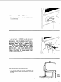
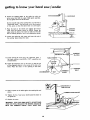
INSTALLING
MOTOR
\
PULL
CORD CLAMP
1. Find the cord clamp and one 8-32 x 3/8 pan hd. self
threading screw and install below the motor-cord outlet
as shown.
CLAh
17
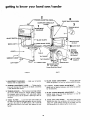
getting to know your band saw/sander
2
8
TENSION ADJUSTING
GUIDE BAR LOCK SCREW
KNOB--_
COVER RETAINING
CLIP
3
"_
1
.......
ON-OFF
ADJUSTMENT
DIAGRAMS
TENSION SCALE
(Inside)
(4-Used)
SWITCH -_
BLADE GUARD
<--UPPER
WORK LIGHT
)TOR CORD
OUTLET
BLADE GUIDE
GUIDE
COVER
1
•
,,WOUSTE,.BO
t
"7
TABLE
TILT SCALE
TILT POINTER
LEFT FOOT /
_'---R
IGHT FOOT
BAR
THRUST
BEARING
ADJ. KNOB
(Lower Knob
Not Shown)
TI LT LOCK
HANDLE
SAW PULLEY
BLADE GUIDE
ADJ. KNOB
(Lower Knob Not Shown)
BA CK
FRONT
1. ADJUSTMENT DIAGRAMS . . . Help you
familiar with the adjustments.
to become
5.
2. TENSION ADJUSTMENT
KNOB . . . Tightening the
knob will increase the tension on the blade. Loosening
it will decrease the tension.
6,
3. TENSION SCALES...
The fractional markings indicate
the correct blade tension for various widths of blades.
For example, when installing a 1/4" wide blade, tighten
the tension knob until the pointer is pointing to the 1/4
marking.
7,
4. TABLE TILTING ... Loosen the table lock handle, tilt
the table to the desired angle and tighten the lock handle.
To return the table to the 90 ° position, tilt it until the
90 ° stop screw rests on the frame, then tighten the lock
handle.
8,
18
BLADE GUIDE ADJUSTMENT
. . • Turning the knob
moves the guides in or out for various widths of blades.
LATERAL BLADE GUIDE ADJUSTMENT
• • • The
guides can be adjusted sideways and locked in position
by the setscrews.
BLADE THRUST BEARING ADJUSTMENT..
• Turning the knob moves the thrust bearings in or out for
various widths of blades.
GUIDE BAR LOCK SCREW...
The upper blade guides
should just clear the workpiece while cutting. Always
adjust the guides before turning on the band saw and
lock the guide bar by tightening the thumb screw.
9. GUIDEBAR
When the upper guides are raised or lowered, they must
not deflect the blade sideways. This means that the guide
bar must be parallel
to the blade, or square with the
table.
=------_-_-_-_____=
__
SCREW
1. Remove the blade guard, cover, blade, and the upper
guide assembly.
(4 Total)
_¢"_"_'_
2. Lower the guide bar until the end is approximately
1-3/4" from the table.
3.
Hold
a square
on
the
table
against
the
guide
4.
If the bar is not square with the table, lock
bar and loosen
the four
screws in the
support
with a 3/16"
setscrew wrench. To
lower left screw, it will be necessary to tilt
wheel outward.
_°il
J-
,3/16"
SETSCREW
W.ENCH
bar.
GU,OE
BAR
the guide
guide bar
reach the
the upper
NOTE:
The holes in the guide bar support
are larger
than the screws. This allows the support
to be moved.
5. Move the guide bar until
then tighten the screws.
6. Be sure to
INSTALLING
replace
SANDING
it is square
the blade
guard
with
before
the
table,
operation.
\
ATTACHMENT
II
WARNING:
FOR YOUR OWN SAFETY, TURN SWITCH
"OFF" AND ALWAYS REMOVE PLUG FROM POWER
SOURCE OUTLET BEFORE INSTALLING
SANDING
ATTACHMENT.
1. Remove the blade guard, the table insert, and the table
alignment screw.
2. Remove the cover, release the blade tension and remove
the blade.
HEX.
HD.
SCREW_K((_))I"_---UPPER
BLADE
ASSEMBLY
3. Remove the upper blade guide assembly. Use a 7/16"
wrench to remove the screw.
4. Loosen the setscrew that locks the lower thrust bearing,
and move the bearing as far back as it will go.
5. Loosen the two setscrews that lock the lower blade
guides. Spread them apart so that the end of each guide
is inside the holder.
19
GUIDE
getting to know your band saw/sander
6. Attach the sanding platen to the guide bar with the
same screw that held the upper blade guide assembly.
Do not tighten the screw at this time.
On the smooth side of the sanding belt, you will find a
"directional arrow". The belt must run in the direction
of this arrow so that the splice does not come apart.
7. Place the belt on the wheels and tighten the tension
knob until the pointer points to SAND. Rotate the
upper wheel by hand a few times to make sure that the
belt is tracking properly and is not rubbing the guides.
4-- SANDING
PLATEN
8. Loosen the guide bar lock screw and lower the end of
the sanding platen below the table.
.<p-=-
JCENTER OF SLOT L_
I
9. Locate among the loose parts, the alignment plate, a
flat head machine screw 6-32 x 7/16", asmall hex nut
SANDING
PLATEN
TABLE INSERT
and Iockwasher.
t0. Attach the alignment plate to the insert so that the end
of the alignment plate is in the center of the slot in the
insert. Place the insert in the opening in the table.
/
/
_'
/_LAT__..D..
SCREW
_
i
Y@ALIGNMENT
LOCKWASHE
_,
/
J/
r----"
PLATE
-,-----SANDING
BELT
AND PLATEN
1 1. Hold a square
platen.
12.
on the table against the sanding
Tighten the hex.
the guide bar.
belt and
_,TION SQUARE
head screw
which
holds the platen
to
13. Replace the cover.
• _,RNING:
FOR YOUR OWN SAFETY, DO NOTSAND
IRON OR STEEL BECAUSE THE SPARKS COULD IGNITE THE SAWDUST INSIDE
YOUR
BAND SAW.
20
basic band saw/sander
BASIC BAND SAW/SANDER
operation
OPERATION
A band saw is basically a "curve cutting"
machine.
It differs
from a saw in two respects. It is capable of cutting thicker
material
and it cuts faster. Unlike
a saw, it is not capable
of doing inside cutting.
Your Craftsman
Band Saw/Sander
is not only capable of
the usual band saw operations,
but it can be converted
into
a sander as well. You can finish wood, certain compositions
and plastics and non-ferrous
metals.
SAWING
3. The smallest diameter
1. Adjust the upper guides to just clear the workpiece.
2. Use both hands while feeding the work into the blade.
Hold the workpiece
firmly
against the table. Use gentle
pressure, and do not force the work, but allow the blade
to cut.
BLADE
BLADE
SIZE
SELECTION
1"
3"
GUIDE
FOR
MINIMUM
CIRCLE
1"
rapidly.
Practice
with
some
you attempt
to sand your
1. Press the workpiece
gently
against
the sanding
and keep moving it until the edge is smooth.
can be cut out
CUTTING
3"
SANDING
The sanding
belt cuts very
scraps of wood
first
before
actual workpiece.
that
is determined
by the width
of the blade. For example,
a 1/4"
wide
blade will cut a minimum
diameter
of approximately
1-1/2".
(See Chart)
belt,
21
1"
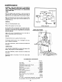
maintenance
WARNING:
FOR YOUR OWN SAFETY, TURN SWITCH
"OFF"
AND REMOVE PLUG FROM POWER SOURCE
OUTLET BEFORE MAINTAINING
OR LUBRICATING
YOUR BAND SAW.
MOTOR OUTLET
ON-OFF SWITCH
TIRES
Pitch and sawdust that accumulate on the tires should be
removed with a stiff brush or scraped off with a piece of
wood. Do not use a sharp knife or any kind of solvent.
C A
When the tires become worn they should be replaced. When
replacing the tires, stretch them around the wheels but do
not glue them on.
t
GENERAL
L rJWHI'ElWH'TE --- I
pOA_E!CLORD
_1
GREEI
GREEN
===
GROUND
Ill
Keep your Band Saw/Sander clean.
Remove the sawdust from the inside.
Wl RING
Do not allow pitch to accumulate on the table, the insert,
the guides or the thrust bearings. Clean them with Craftsman Gum and Pitch Remover. CAUTION: Do not immerse
tke thrust bearings.
WHEEL NOT SHOWN
FOR PICTURE
CLARITY
Apply a thin coat of automobile-type wax on the table so
that the wood slides easily while cutting.
MOTOR
Frequently blow out any sawdust from the motor.
If the power cord is worn or cut, or damaged in any way,
have it replaced immediately.
For motor maintenance, follow instructions furnished with
the motor.
GUIDE RODS
/
LUBRICATION
All of the BALL BEARINGS are packed with greaseatthe
factory. They require no further lubrication.
For motor lubrication, follow instructions furnished
the motor.
with
Periodically apply a few drops of oil to the upper wheel
guide rods.
RECOMMENDED
ACCESSORIES
Item
Cat. No.
Floor Base .........................
Miter
BLACK
9-22213
Gauge ........................
Hold-Down
Clamp
Stop-Rods
for Miter
Rip Fence
.........................
9-29929
for Miter
Gauge
Gauge ..............
9-29926
9-29924
9-23433
Blades and Sanding Belts ............
Steel Leg Set .......................
Circle
Table
Cutting Attachment
..............
Extension
.....................
Speed
Power
Reducer .....................
Tool Know How Handbooks
Radial
Saw
Table Saw
........
........................
See Catalog
9-22236
9-24301
9-24302
9-238961
9-2917
.........................
9-2918
The above recommended
accessories are current
were available at the time this manual was printed.
22
and
DIAGRAM
L
mII
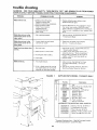
trouble shooting
WARNING:
FOR YOUR OWN SAFETY, TURN SWITCH "OFF" AND REMOVE
SOURCE OUTLET BEFORE TROUBLE SHOOTING YOUR BAND SAW/SANDER.
PROBABLE
TROUBLE
Motor will not run.
1. Defective
Defective
CAUSE
REMEDY
On-Off switch.
switch cord.
1. Replace defective parts before using
Band Saw/Sander again.
Defective
switch box receptacle.
2. Motor protector
open,
(only if your motor is
equipped
with an
overload protector).
Other cause.
Blade does not run in the
1. Not
tracking
2. Consult Sears Service. Any attempt
to repair
this motor may create a HAZARD
unless
repair is done by a qualified
service technician.
Repair service is available at your nearest Sears
Store.
properly.
1. Adjust tracking,
see Assembly
"Installing
the Blade."
not positioned
shaft.
1. Reposition
the wheel, see Assembly
Section, "Installing
the Blade."
approximate center of the
upper wheel.
Blade does not run in the
approximate center of the
lower wheel.
Band Saw slows down when
1. Lower wheel
correctly
on
1. Belt too loose.
pivots
3. Cutting
4.
Blades breaking.
in motor
base.
too small a radius.
3. Stop feeding, and back up the material
slightly, until the band saw speeds up.
4. Replace blade.
Dull blade.
1. Too
much tension.
2. Kink in blade caused by cutting
too small a radius or turning the
material too fast when cutting.
FIGURE
Section,
1. Adjust belt tension, see Assembly
Section,
"Attaching
Belt Guards."
2. Tighten motor base clamp screws. See
Assembly
Section, "Motor
Installation".
cutting.
2. Motor
PLUG FROM POWER
1
1. Adjust tension. See Getting To Know
Your Band Saw!Sander,
"3 Tension
Scales."
2. Use correct cutting technique.
See Basic
Band Saw/Sander
Operation
SUPPLIED WITH MODEL
Section.
113.243411
ONLY
Key
No,
1
2
3
4
5
7
8
10
11
12
I
_.,.
2
Part No.
62614
60314
STD541025
STD551225
68060
68059
62615
68061
STD541050
803835
69097
HARDWAREFOR
STD523110
STD551131
STD541231
STD551031
STD532507
Description
Leg
t'Screw
Truss Hd. 1/4-20 x 5/8
t'Nut
Hex 1/4-20
t*Lockwasher,
1/4 External
Channel, Support
Stiffener,
Side
Stiffener,
End
Support,
Motor
t'Nut,
Hex Hd. 1/2-13
t Foot, Leveling
*Bag of Loose Parts
MOUNTING
TOOL
& MOTOR
t'Screw,
Hex Hd. 5/16-18
t*Lockwasher
Ext. 5/!6
x 1
t'Nut,
Hex Jam 5/16-18
t'Washer
11/32 x 11/16
x 1/t6
t'Bolt,
x 3/4
Carriage
5/16-18
10
* Standard
Hardware
1- All Parts Contained
23
Item -- May Be Purchased
In Loose Parts Bag
Locally
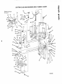
CRAFTSMAN
12-INCH
BAND SAW/SANDER,
MODEL
113.243401
& 113.243411
"O
Q
no
/
2
"O
31 30
SEE FIGURE
FOR
EXPLODED
VIEW
29
15
32
\
I
11 27
14
3:3
/
/
\
43 ..-.--._ m
38
37
36
1
3
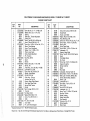
CRAFTSMAN
12-INCH BAND SAW/SANDER,
Always
order
by Part Number
FIGURE
KEY
NO.
PART
NO.
1
2
3
4
5
6
7
8
9
10
11
12
13
14
15
69069
41815
38524
37158
41711
STD315228
69028
41-812
60256
69085
60251
38884
STD601105
STD580104
STD503105
16
38450
17
18
60255
60252
19
20
STD304520
30646
21
22
60254
60253
Frame with
- not
Trim
Screw, Self-Locking
Ring, Retaining 5/8
Washer, Spring
Bearing, Ball
Wheel, Upper Drive
Ring Internal
Retaining
1-3/8
Key, Switch
Clip
Bearing, Ball
Ring, Internal
Retaining
1-11/16
*Screw Type 23, 10-32 x 1/2, Pan Hd.
*Key, Square 3/16 x 1-1/4
*Screw, Set, 5/16-18 x 1/2, Soc. Hd.,
Cup Pt.
tPulley,
1/2 V Groove, 5" x 5/8
Bore, Keyed with Set Screw
Clip, "S"
Guard, Belt
tBelt "V" Type, 1/2 x 52
tPulley,
1/2 V Groove, 2-1/2"
Bore, Keyed with Set Screw
Bracket, Support
Support,
Belt Guard
x 5/8
113.243401
& 113.243411
by Key Number
2 PARTS LIST
KEY
NO.
DESCRIPTION
Cover,
Tire
MODEL
PART
NO.
23
24
25
26
453068
69084
STD541031
STD522503
27
28
29
3O
31
32
33
34
35
36
37
38
39
40
41
42
43
44
69023
65013
69004
STD601103
69078
69059
69058
69025
60272
37887
60096
37911
69062
133427
69005
STD551106
STD541Q06
69037
69098
69086
69088
DESCRI PTION
*Screw, 5/16-18 x 3/4, Sems, Hex, Hd.
Foot, Frame
*Nut, Square, 5/16-18
*Screw Mach., 1/4-20 x 3/8, Truss
Hd., Slotted.
Spacer, Bearing
Elbow
Clamp,
*Screw,
Gasket,
Wheel,
Shaft,
Lens
Tube
Mach., 10-32
Foam
Lower Drive
Lower Wheel
x 3/8,
Pan Hd.
tBlade, Band Saw, 1/4 x 80
tWrench,
Hex., "'L", 1/8
tWrench,
Hex., "L", 5/32
tWrench,
Hex., "'L", 3/16
Platen, Sanding
*Screw, Mach., 6-32 x 7/16, Flat
Hd.
Plate, Sanding Alignment
* Lockwasher,
No. 6
*Nut, Hex., 6-32
tBelt, Sanding, 1/2 x 80
Owner's Manual (Not Illustrated)
Bag Asm. Loose Parts (Not Illustrated)
Bag Asm. Loose Parts (Not Illustrated)
i|
*Standard
tStock
Hardware Item - May Be Purchased Locally.
Item - May be secured through the Hardware Department
of most Sears or Simpsons-Sears Retail Stores or Catalog Order Houses.
CRAFTSMAN
12-1NCH BAND SAW/SANDER,
MODEL
113.243401
& 113.243411
fl
le
'10
==
O_
CRAFTSMAN
12-INCH
BAND SAW/SANDER,
FIGURE
KEY
NO.
PART
NO.
MODEL
113.243401
& 113.243411
3 PARTS LIST
KEY
NO.
DESCRI PTION
PART
NO.
DESCRI PTION
ll,
i
1
2
3
4
5
6
7
8
9
10
11
12
13
14
15
16
17
18
19
20
21
22
23
24
25
STD522503
STD551050
63266
69031
30613
STD600803
60321
STD502502
69042
69046
69047
69048
69049
69021
STD541037
69077
69072
STD551037
38724
69070
STD551131
9416187
69029
STD572507
69068
26
27
28
29
30
31
32
33
34
35
36
37
38
41426
69022
69019
69089
STD533725
69057
STD541625
STD551025
60323
69094
STD571203
69063
69O24
*Screw Hex Hd, Ty "T", 1/4-20 x 3/8
Washer, Plain, 1/2 x 1-1/4 x 1/8,
Bushing
Knob Assy., Tension Adjustment
Clamp, Cord
*Screw, Type 23, 8-32 x 3/8 Pan Hd.
Screw, Thumb 5/16-18 x 1-1/2
*Screw, Set, 1/4-20 x 1/4 Soc. Hd., FI. Pc.
Sleeve, Thrust Bearing
Screw, Thrust Adjustment
Washer, 1/4 x 1-13/32 x 1/16
KNob, Lower Guide
Screw, Guide Adjustment
Pin, Trunnion
*Nut, Hex. 3/8-16
Spacer
Wrench
*Washer, Plain, 3/8 x 1-1/8 x 7/64
Pointer, Tilt
Frame Assy., (Incl. Key Nos. 14 & 36)
* Lockwasher Ext. 5/16
*Screw, Hex. Hd. 5/1618 x 3/4
Bumper, Upper Wheel
Pin Roll 1/4 x 3/4
Guide Assy., Fulcrum
(includes Key No. 24)
Bracket, Upper Wheel Support
Rod, Upper Wheel Guide
Spring, Wheel Tension
Pointer
*Bolt, Carriage, 3/8-16 x 2-1/2
Trunnion
*Nut Wing 1/4-20
*Washer 9/32 x 5/8 x 1/16
Screw, Truss Hd 1/4-20 x 1
Table
*Pin, Roll 1/8 x 5/16
Insert Table
Pin, Lower Guide Support
39
4O
41
42
43
44
45
46
47
48
49
50
51
52
53
54
55
56
57
58
59
61
62
60190
69039
69045
STD551031
STD581031
STD502505
STD512505
STD315505
69038
STD522508
STD551125
69041
STD601103
69044
69043
69035
216278
69036
69034
69012
30682
STD551225
STD522512
STD372252
63
64
65
66
67
68
69
70
71
72
73
74
75
76
69014
STD551208
STD510802
69009
STD600603
STD551206
447845
69010
60257
69082
69026
STD375006
69027
37875
60
Screw, Self-Locking, 5/16-18 x 3/8
Guide, Blade
Guide, Lower Blade
*Washer, Plan, 5/16 x 9/16 x 1/16
Ring, Retaining, 5/16
*Screw, Set, 1/4-20 x 3/4, Soc. Hd., FI. Pt.
*Screw, Mach., 1/4-20 x 1/2, Pan Hd.
Bearing, Ball
Guide, Upper Blade
*Screw, Mach., 1/4-20 x 7/8, Hex. Hd.
*Lockwasher, 1/4
Support, Upper Blade
"Screw, Type 23, 10-32 x 5/16, Pan Hd.
Guard
Knob Upper Guide
Bar, Guide
*Screw, Cap, 1/4-20 x 1/2, Socket, Hd.
Support, Guide Bar
Spring, Guide Bar
Spacer
*Nut, Speed
* Lockwasher, External Tooth 1/4
*Screw, Mach., 1/4-20 x 1-1/4, Pan Hd.
*Bulb, Light 115/125V, 25 Watt, Dbl.
contact, Bayonet Base,Appliance
Socket, Light
* Lockwasher No. 8
*Screw Mach., Pan Hdo 8-32 x 1/4
Relief, Strain
*Screw, 6-32 x 3/8, Pan Hd.
Lockwasher, Int. 6
Screw, Type T, 1/4-20 x 1/2, Pan Hd.
Box Assy., Switch
Switch, Locking
Gasket, Switch Box
Cord Assembly
*Connector, Wire, 14-18
Outlet Assembly
Relief, Strain
*Standard Hardware Item - May Be Purchased Locally.
fStock
Item - May be secured through the Hardware Department
of most Sears or Simpsons-Sears Retail Stores or Catalog Order Houses.
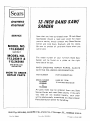
]Sears[
12-INCH BAND SAW/
owners
manual
SANDER
SERVICE
Now
that
you
Saw/Sander
parts
or
Center
MODEL NO.
113.243401
have
purchased
should
service,
and
Be
sure
call
or visit.
The
model
a
to
need
simply
most
your
ever
contact
Sears,
12-Inch
exist
any
Roebuck
provide
all
pertinent
number
of
your
Band
for
Sears
and
repair
Service
Co.
facts
stores.
when
you
SAW ON LY
MODEL NO.
113.243411 &
113.243440
Sander
hand
SAW WITH LEGS
AND MOTOR
will
be
found
side of the
on
12-Inch
a
plate
Band
Saw/
the
right-
at
saw.
WHEN
ORDERING
REPAIR
PARTS,
GIVE THE FOLLOWING
INFORMATION"
HOW TO ORDER
REPAIR
PARTS
PART NUMBER
PART DESCRIPTION
MODEL NUMBER
113.243401
113.243411
NAME OF
ALWAYS
ITEM
12-Inch Band Saw/Sander
or
113.243440
All
parts
Service
you
SEARS,
Part No. 69098
ROEBUCK
may
and
are
not
be electronically
Parts
by
Center
need
will
Sold
listed
Distribution
AND
Form
CO.,
No. SP4432-6
be
most
ordered
Sears
stocked
from
stores.
Chicago,
for
If the
Sears
parts
locally,
your
order
to
a Sears
Repair
transmitted
Center
any
handling.
IL.
60684
Printed
U.S.A.
in U,S.A,
5/81