1
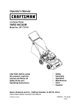
I::RRF rSM FIN
5 Horsepower
22 inch Dual Stage
120V, Electric Start
SNOWTHROWER
MODEL NO=
536.886122
Caution:
Readand follow all Safety
Rules and Operating
Instructionsbefore first use
of this product.
SEARS, ROEBUCK AND CO., Hoffman Estates 60179 U.S.A.
760015 08102/96
Table of Contents
Warranty
Safety Rules
Contents of Shipping Carton
Assembly
Operation
Maintenance
LIMITED
TWO-YEAR
Service and Adjustments
Storage
Troubleshooting
Repair Parts
Engine Repair Parts
Spanish(EspaSol)
Parts Ordering/Service
2
2-4
4-5
5-8
8-14
14-16
WARRANTY
ON CRAFTSMAN
SNOW
17-21
22
23
24-32
33-37
38-62
Back Cover
THROWER
For two years from the date of purchase, when this Craftsman Snow Thrower is maintained, lubricated, and tuned up according to the operating and maintenance instructions in the owner's manual, Sears will repair, free of charge, any defect in material or
workmanship°
If this Craftsman Snow Thrower is used for commercial or rental purposes, this warranty applies for only 90 days from the date of purchase.
This warranty does not cover the following:
• Items which become worn during normal use, such as spark plugs, drive belts and
shear pins.
• Repairs necessary because of operator abuse or negligence, including bent crank
shafts and the failure to maintain the equipment according to the instructions contained in the owner's manual.
WARRANTY SERVICE IS AVAILABLE BY RETURNING THE CRAFTSMAN SNOW
THROWER TO THE NEAREST SEARS SERVICE CENTEPdDEPARTMENT IN THE
UNITED STATES. THIS WARRANTY APPLIES ONLY WHILE THIS PRODUCT IS tN
USE IN THE UNII1ED STATES°
._
This warranty gives you specific legal rights, and you may also have other rights which
may vary from state to state.
Sears, Roebuck and Co., D817WA, Hoffman Estates, IL 60179
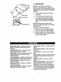
Look for this symbol to point out important safety precautions, it means--ATTENTION!!! Become alert!!! Your safety is involved.
CAUTION: Always disconnect spark
plug wire and place wire where it cannot
contact spark plug to prevent accidental
starting when setting-up, transporting,
adjusting or making repairs.
IMPORTANT:
Safety standards require
operator presence controls to minimize the
risk of injury° '(our snow thrower is
equipped with such controls. Do not attempt
to defeat the function of the operator
presence control under any circumstances.
TRAINING
1. Read the operator's manual carefully.
Be thoroughly familiar with the controls
and the proper use of the snow thrower.
Know how to stop the snow thrower and
disengage the controls quickly.
2. Never allow children to operate the snow
thrower and keep them away while it is
operating. Never allow adults to operate
the snow thrower without proper instruction. Do not carry passengers.
Keep the area of operation clear of all
persons, particularly small children and
pets.
3_
.
Exercise caution to avoid slipping or
falling, especially when operating in
reverse.
PREPARATION
1_ Thoroughly
inspect the area where the
snow thrower is to be used and remove
all doormats, sleds, boards, wires and
other foreign objects.
2.
Disengage all clutches
engine (motor).
before
starting the
3.
Do not operate the snow thrower
without wearing adequate winter outer
.
garments,Wear footwear that will
improve footing on slippery surfaces.
Handle fuel with care; it is highly
fl_immable.
(a) Use an approved fuel container.
(b) Never remove fuel tank cap or add
fuel to a running engine or hot
engine.
(c) Fill fuel tank outdoors with extreme
care. Never fill fuel tank indoors.
(d) Replace fuel tank cap securely and
wipe up spilled fuel.
(e) Never store fuel or snow thrower
with fuel in the tank inside of a
building where fumesmay reach an
open flame or spark.
(f) Check fuel supply before each use,
allowing space for expansion as the
heat of the engine (motor) and/or sun
can cause fuel to expand.
5. Use extension cords and receptacles as
specified by the manufacturer for all
snow throwers with electric drive motors
or electric starting motors.
1_, Adjust the snow thrower height to clear
gravel or crushed rock surfaces,
7. Never attempt to make any adjustments
while the engine (motor) is rL]nning
(except when specifically recommended by the manufacturer).
13°Let engine (motor) and snow thrower
adjust to outdoor temperatures before
starting to clear snow.
_. Always wear safety glasses or eye
shields during operation or while
performing an adjustme_nt or repair to
protect eyes from foreign objects that
may be thrown from the snow thrower.
OPERATION
1. Do not operate this machine if you are
taking drugs or other medication which
can cause drowsiness or affect your
ability to operate this machine.
Z. Do not use this machine if you are
mentally or physically unable to operate
this machine safely.
3. Do not put hands or feet near or under
rotating parts. Keep clear of the
discharge opening at all times.
$. Exercise extreme caution when
operating on or crossing gravel drives,
walks, or roads. Stay alert for hidden
hazards or traffic_
3. After striking a foreign object, stop the
engine (motor), remove the wire from
6.
7.
8.
9.
the spark plug, disconnect the cord on
electric motors, thoroughly inspect the
snow thrower for any damage, and
repair the damage before restarting
and operating the snow thrower.
If the snow thrower should start to vibrate
abnormally, stop the (motor) and check
immediately for the cause. Vibration is
generally a warning of trouble.
Stop the engine (motor) whenever Y
leave the operating position, before °u
unclogging the auger/impeller housing or
discharge guide, and when making any
repairs, adjustments, or inspections.
When cleaning, repairing, or inspecting,
make certain the augedimpeller and all
moving parts have stopped. Disconnect
the spark plug wire and keep the wire
away from the plug to prevent accidental
starting.
Take all possible precautions when
leaving the snow thrower unattended.
Disengage the auger/impeller, stop
engine, and remove key.
10. Do not run the engine indoors, except when
starting the engine and for transporting the
snow thrower in or out of the building. Open
the outside doors; exhaust fumes are
dangerous (containing CARBON
MONOXIDE, an ODORLESS and
DEADLY GAS).
11. Do not clear snow across the face of
slopes. Exercise caution when changing
direction on slopes. Do not attempt to
clear steep slopes.
12. Never operate the snow thrower without
proper guards, plates or other safety
protective devices in place.
13. Never operate the snow thrower near
glass enclosures, automobiles, window
wells, drop-offs, and the like without
proper adjustment of the snow discharge
angle. Keep children and pets away.
14. Do not overload the machine capacity by
attempting to clear snow at too fast a
rate.
15. Never operate the snow thrower at high
transport speeds on slippery surfaces.
Look behind and use care when backing.
16. Never direct discharge at bystanders or
allow anyone in front of the snow
thrower.
17. Disengage power to the auger/impeller
when snow thrower is transported or not
in use.
18. Use only attachments and accessories
approved by the manufacturer of the
snow thrower (such as tire chains,
electricstart kits, etc.)°
19. Never operate the snow thrower
"without good visibility or light. Always be
sure of your footing, and keep a firm
hold on the handles. Walk; never run.
\
WARNING;
The engine exhaust
from this product contains chemicals
known to the State of California to cause
cancer, birth defects or other reproductive
tlarm.
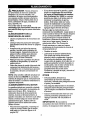
MAINTENANCE
/_
.
AND STORAGE
WARNING:
This snow thrower is for
use on sidewalks, driveways and other
ground level surfaces.
Check shear bolts and other bolts
frequently for proper tightness to be
sure the snow thrower is in safe working
condition.
Caution should be exercised while using on
steep sloping surfaces. DO NOT USE
SNOW THROWER ON SURFACES
ABOVE GROUND LEVEL such as roofs of
residences, garages, porches or other such
structures or buildings.
2. Never store the snow thrower with fuel
in the fuel tank inside a building where
ignition sources are present Such as hot
water and space heaters, clothes
dryers, and the like. Allow the engine to
cool before storing in any enclosure.
3. Always refer to operator's manual
instructions for important details if the
snow thrower is to be stored for an
extended period.
4. Maintain or replace safety and instruction labels, as necessary°
5. Run the snow thrower a few minutes
after throwing snow to prevent freezeup of the auger/impeller.
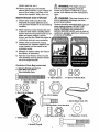
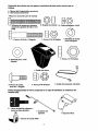
Contents of Parts Bag (actual size)
1 - Owner's Manual (not shown)
2 - Parts Bags (not shown)
*Non-Assembly Parts
*2 - Spare Spacers
*2 - Spare 1/4-20 Hex Nuts
(1/4-20 x 1-3/4 In.)
DG
1- Nut, 5/16-18 Reghex
1-Nut,
1/2-13 Hexjam
1 - Starter Motor Cord 10Ft.
3 -Carriage
Bolts, 5/16-18xl .00 In.
DG
3 -Hex Nylon Nuts, 5/16-18
1- Shifter Knob
I
_-_
4 - Flatwashers 11/32 In.
}
1 -Washer_ Hvsptlk
1- Screw, 5!16-18 x 2 In.
4
Parts packed separately in carton (not shown full size)
2 - Ignition Keys
(Attached
to engine in plastic bag)
1 - container 5W30 oil
=,
1 - Snow Chute Assembly
A
/_
CAUTION: Always wear safety
glasses or eye shields while assembling
snow thrower.
TOOLS
REQUIRED
FOR ASSEMBLY
1 - Knife to cut carton and plastic ties
2 - 1/2 inch wrenches (or adjustable
wrenches)
2 _ 9/16 inch wrenches (or adjustable
wrenches)
2 - 3/4 inch wrenches (or adjustable
wrenches)
1 - Pliers (to spread cotter pin)
1- Screwdriver
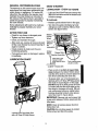
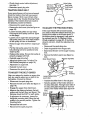
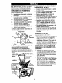
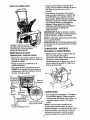
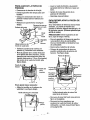
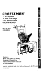
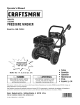
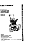
The figure below shows the snow thrower
completely assembled.
References to the right or left hand side
of the snow thrower are from the viewpoint
of the operator's position behind the unit,
Auger drive lever
assembly
Shifter
lever
1 - Measuring tape or ruler
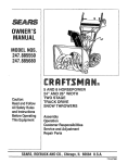
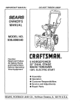
The figure below shows the snow thrower in
the shipping carton.
Lower
Clutch
Height
adjust
Upper
handle
assembly
drive lever
........
deflec_r
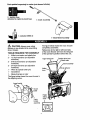
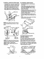
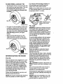
TO REMOVE SNOW THROWER
FROM CARTON
= Locate and remove container of 5W30 oil.
= Locate all parts packed separately and
remove from the carton.
- Remove and discard the packing material
from around the snow thrower.
• Cut all four corners of the carton from top
to bottom and lay the panels flat.
° Roll the snow thrower off the carton by
pulling on the lower handle. CAUTION:
DO NOT back over cables.
- Remove the packing material from
handle assembly and plastic protector on
top of auger housing°
. Cut ties securing the clutch control cables
to the lower handle and lay cables back
away from the motor frame.
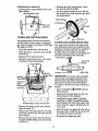
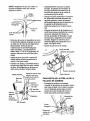
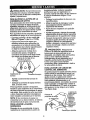
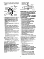
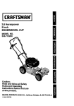
TO INSTALL THE UPPER HANDLE
AND CRANK ASSEMBLY
Reinstall flatwasher and adapter. Install
eye bolt through lower hole in the left
hand side of the handle. See figure below.
Install the 3/8" flatwasher and the 3/8" nylon Iocknut on the eye bolt as shown in
figure below.
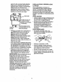
Carefully remove cotter pin, clevis pin and
universal joint pin from yoke end of crank
rod assembly as shown in second figure
below.
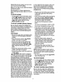
, Place universal joint into end of worm
gear lining up large holes. Insert universal
joint pin (ensure opening in pin is in line
with small openings in universal joint)°
• Place yoke end of crank rod around universal joint, lining up openings. Insert
clevis pin through assembly and secure
with cotter pin. Spread ends of cotter pin
to lock in place. See figure below.
Adjust nuts to move
bolt in or out
,, Loosen, but do not remove the screws,
flatwashers, lockwashers and hex nuts in
the upper holes of the lower handle. See
next figure.
° Raise upper handle into operating position. Upper handle should be to the
outside of the lower handle.
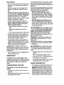
NOTE: Make sure the cables are not
caught between the upper and lower
handle.
Install hardware supplied in the parts bag
(Screw, flatwasher, lockwasher, and hex
nut) into middle hole on right hand side of
handles. Do not tighten until all bolts are
in place.
Locate crank assembly removed earlier
and remove the 3/8" nylon iocknut and
flatwasher from the eye bolt assembly.
Check to make sure the two 3/8" jam nuts
are tight. The jam nuts should be 2.75
inches from the end of the eye bolt. See
figure on next column.
Iocknut
flatwasher
Bolt
Flatwasher
• Tighten nut on eye bolt, keeping eye in
line with the rod while tightening the inside securely.
• Tighten all handle bolts.
! t
_\'\
| 1
. Upper handle
!
Crank Rod
_1Clevispin
Assembly
t u JA
11/32" Flatwasher
5/16" hex Nu
Screw
5/!6" Lockwasher
_
Universaljoint
I \Worm Mounting
Bracket
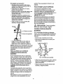
TO INSTALL SHIFTER LEVER KNOB
TO ASSEMBLE
Thread the hex nut found in the parts bag
onto shifter lever. Thread the shifter lever
knob onto the threaded end of the shifter
lever until it is snug against the hex nut
and the lip is pointed away from the engine. Tighten hex nut against the bottom
of the shifter lever knob. See figure below.
,,
\
SNOW CHUTE
• Turn crank assembly counterclockwise
until it stops.
• Locate three carriage bolts, flatwashers
and nuts (found in parts bag) for snow
chute flange. DO NOT remove carriage
bolt over worm gear.
- Position snow chute on snow chute flange
and align the three holes in the snow
chute with holes in the snow chute flange
as shown in figure below.
, Install carriage bolts from inside of chute
as shown in figure below, flatwashers and
nuts.
Knob
Nut
Shifter Lever
Tighten all four nuts on snow chute flange
securely. See figure below.
Locknut
NOTE: If the cables have become disconnected, reinstall spring as shown in figure
below.
4" Lg free state
Traction drive
s
Chute
3" Lg free state
Auger drive
ing
Snow Chute Flange
Bolts
d
TO CHECKJADJUST
CONTROL CABLES
drive
spring lever
Au
drive
spring cable
CLUTCH
The control cables attached to the auger
clutch lever and traction clutch lever as
shown in figure below may need to be adjusted before you use your snow thrower.
NOTE: if the cables have become disconnected from the clutch levers, reinstall the
cables as shown in figure below.
NOTE: Position cable through slots on
shifter plate.
For instructions on checking or adjusting the
control cables, (See To Adjust Clutch Control
Cables paragraph on page17).
TractionClutchLever
Auger ClutchLever
"Z" fitting
7
\:v
Controlcables ¢
ON
4" CHECKLIST
Flatwasher Locknut
Before you operate your new snow
thrower, to ensure that you receive the
best performance and satisfaction from this
quality product, please review the following
checklist:
All assembly instructions have been
completed.
Chute
Snow Chute Flange
e Bolts
Auger Drive Lever - Starts and stops the
auger and impeller (snow gathering and
throwing).
Traction Drive Lever - Propels the snow
thrower forward and in reverse.
Speed Shifter Lever - Selects the speed of
snow thrower (6 speeds forward and 2
speeds reverse),
Crank AssemblyChanges the direction of
snow throwing through the discharge chute.
Chute Deflector - Changes the distance
the snow is thrown,
Discharge Chute - Changes the direction
the snow is thrown.
Height Adjust Skids - Adjusts the ground
clearance of the auger housing,
,f
,#
The discharge chute rotates freely.
No remaining loose parts in carton,
except for extra shear bolt assembly
parts. Keep in safe place for replacement.
While learning how to use your snow
thrower, pay extra attention to the following
important items:
_',f Engine oil is at proper level.
,#/ Make sure gas tank is filled properly
with clean, fresh, unleaded gasoline.
_'#" Become familiar with all controls-their
location and function. Operate controls
before starting engine.
Ignition Key- Must be inserted to start the
engine.
Recoil Starter Handle - Starts the engine
manually.
Choke Control - Used to start a cold engine.
Primer Button - Injects fuel directly into the
carburetor manifold for fast starts in cold
weather.
Throttle Control - Controls the engine
speed.
Electric Starter Button - Used to start the
engine using the 120 V electric starter.
Shear Bolt -, Shear bolts are designed to
break (to protect the machine) if an object
becomes lodged in the auger housing. Use
of a harder bolt wiU destroy the protection
provided by the shear boll
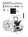
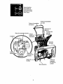
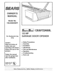
KNOW YOUR SNOW THROWER
READTHIS OWNER'SMANUALAND SAFETYRULESBEFOREOPERATING",(OUR
SNOWTHROWER.Comparethe illustrationswith yeurSNOWTHROWER to familiarize
yourself with the location of various controls and adjustments. Save this manual for future
reference.
Engine
Start
Engine
Run
Drive Clutch
Off
Choke Off
Fast
Slow
Stop
Fuel
Oil
Primer
Button
Ignition Key
insert to run
pull out to stop
Auger Clutch
Auger Drive Lever
Traction Drive Lever
Crank Assembly
Chute Deflector
Electric Starte
ignition
Speed
Shifter
Lever
Chute
Control
Recoil Starter
Height
Skids
She r Bolt
ScI_
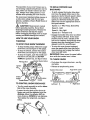
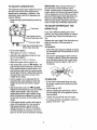
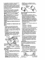
TO MOVE FORWARD AND
BACKWARD
The operation of any snow thrower can result in foreign objects being thrown into the
eyes, which can result in severe eye damage. Always wear safety glasses or eye
shields while operating the snow thrower.
• To shift, release the traction drive lever
and move the speed shifter lever to the
speed you desire. Ground speed is determined by snow conditions. Select the
speed you desire by moving the speed
shifter lever into the appropriate area on
the speed selector.
Speeds 1, 2 -Wet, Heavy, Extra Deep
Speed 3 - Light
Speed 4 -Very Light
Speeds 5, 6 -Transport only
° Engage the traction drive lever as shown
in figure below, left hand. As the snow
thrower starts to move, maintain a firm
hold on the handles, and guide the snow
thrower along the clearing path. Do not
attempt to push the snow thrower,
- To move the snow thrower backward,
move the speed shifter lever into first or
second reverse and engage the traction
drive lever (left hand).
IMPORTANT: Never move the speed shifter
lever while the traction lever is down.
We recommend standard safety glasses or
a wide vision safety mask for over your
glasses, available at Sears Retail Stores or
Service Centers.
L_
CAUTION: Read owner's manual
before operating machine. Never direct
discharge toward bystanders. Release the
auger control bar and stop the engine
before unclogging discharge chute or auger
housing and before leaving the machine.
HOW' TO USE YOUR SNOW
THROWER
TO STOP YOUR SNOWTHROWER
• "lrbstop throwing snow, release the auger
drive lever (see last figure on this page).
• To stop the wheels, release the traction
drive lever (see last figure on this page).
- To stop the engine, push the throttle control lever to off and pull out (DO NOT
TURN) the ignition key, see figure below.
TO THROW SNOW
Push down the auger drive lever,
ure below,
Release
to stop throwing snow.
Traction Drive Lever
conlml
/f "_
Throttle_ontr_
!OffIt/
o.k,..
_'__
' Rec6il starter
handle
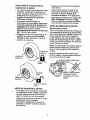
TO CONTROL SNOW DISCHARGE
Left hand
Turn tile crank assembly to set the direction of the snow throwing,
Loosen the wing knob on the chute deflector and move the deflector to set the
distance. Move the deflector (UP) for
more distance, (DOWN) for less distance.
Then tighten the wing knob, see figure
below.
knob
\
lO
see fig-
m,_
.... ._
\
Auger Drive Lever
_Off
....
.
_
Right hand
For extreme cold operating conditions of
O°F and below, use a partial synthetic
OW30 motor oil for easier starting.
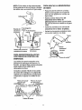
TO USE WHEEL LOCKOUT
PiN
• -The left hand wheel is secured to the axle
with a klick pin see figure below. This unit
was shipped with this klick pin in the
locked position (klick pin through hole
in
I).
NOTE: S.A.E. 5W30 motor oil may be used
to make starting easier in areas where the
temperature is 20 ° E or lower,
Fill/Dipslick
Locked
Position
Klick Pin
r[,,z.-'__..$_Y'
(O'_)Y
2-Wheel Drive
NOTE: Oil level must be
between full and add
mark.
FILL GAS
,
For ease of maneuverability
in light snow
WARNING: Experience indicates that alco,
hoi blended fuels (called gasohol or those
using ethanol or methanol) can attract
moisture which leads to separation and formation of acids during storage. Acidic gas
can damage the fuel system of an engine
while in storage.
conditions, disconnect
the klick pin from
the wheel locked position and push into
the single wheel drive (kllck pin through
axle hole only) position (see figure
below).
:
• Make sure that the klick pin is in the
single wheel drive position of the axle
only and not through
To avoid engine problems, the fuel system
should be emptied before storage for 30
days or longer, Start the engine and let it
run untilthe fuel lines and carburetor are
empty. Use the carburetor bowl drain to
empty residual gasoline from the float
chamber. Use fresh fuel next season (see
Storage instructionson page 22 for additional information).
Never use engine or carburetor cleaner
products in the fuel tank or permanent
damage may occur,
Fill the fuel tank with clean, fresh, unleaded
grade automotive gasoline. Be sure that the
container you pour the gasoline from is
clean and free from rust or other foreign
particles. Never use gasoline that may be
stale from long periods of storage in the
container.
the locked position.
Unlocked
Position
Klick Pin
Single Wheel Drive
BEFORE STARTING THE ENGINE
FILL OIL
This snow thrower was shipped with a container of 5W30 motor oil. This oil must be
added to the engine before operating. Remove the oil fill cap/dipstick and fill the
crank case to (FULl.) line on dipstick (20
ounces) (see next figure). NOTE: Engine
may already contain some residual oil
Check frequently when filling the crankcase, Do not over fill
Tighten the fill capldipstick securely
time you check the oil level.
CAUTION: Gasoline is flammable and
caution must be used when handling or storing it.
Do not fill fuel tank while snow thrower is
running, when it is hot, or when snow
thrower is in an enclosed area.
Keep away from open flame or an electrical
spark and DO NOT SMOKE while filling the
fuel tank.
each
NOTE: Oil must be changed after the first 2
hours of operation to extend engine life.
11
NEVER fill the tank completely. FILL THE
TANK to within 1/4" - 1/2" from the top to
provide space for expansion of fuel.
Alwaysfill fuel tank outdoorsand usea funnel or spoutto preventspilling.
Makesure to wipe up any spilledfuel before
startingthe engine.
Store gasolinein a clean,approvedcon-
on the engine first, then plug the other end
into the three-hole grounded receptacle.
When disconnecting
power cord, always
unplug the end in the three-hole grounded
receptacle first.
tainer and keep the cap in place on the container.
Plug the other end of the power cord into
a three-hole, grounded 120 volt A,C.
receptacle,
Push the primer button while covering the
vent hole as follows: (Remove finger
from primer button between primes).
See figure on page 9 for location,
Do not prime if temperature is above
50OF.
TO STOP ENGINE
To stop e==ngine,move the throttle control
lever to I_i (STOP) position and remove
key. Keep the key in a safe place. The
engine will not start without the key.
NOTE:
DO NOT turn key.
TO START ENGINE (Electric Starter)
Two times iftemperature is 50°F to 15°F.
Four times if temperature is below 15°F,
- Push down on the starter button untilthe
engine starts. Do not crank for more than
10 seconds at a time. This electric starter
is thermally protected, if overheated it will
stop automatically and can be restarted
only when it has cooled to a safe temperature (a walt of about 5 to 10 minutes
is required).
= When the engine starts, release the
starter button and slowly rotate the choke
to (OFF) position. If the engine falters,
rotate the choke to(FULL) and then
gradually to (OFF).
° Disconnect the power cord from the
receptacle first and then from the switch
box on engine.
NOTE: Allow the engine to warm up for a
few minutes because the engine will not develop full power until it reaches operating
temperature.
Be sure that the engine has sufficient oil.
The snow thrower engine is equipped with a
120 volt A.C. electric starter and recoil
starter. Before starting the engine, be certain that you have read the following information:
COLD START
- Be sure the auger drive and traction drive
levers are in the disengaged (released)
position.
- Move the throttle control to ,_ (FAST)
position. See figure on page 9.
, Remove the keys from the plastic bag°
Insert one key into the ignition slot, Be
sure it snaps into place. DO NOT TURN
KEY, Keep the second key in a safe
place,
• Rotate the choke knob to (FULL) choke
position° See figure on page 9.
• Connect the power cord to the switch box
on the engine.
CAUTION: This starter is equipped
with a three-wire power cord and plug
and is designed to operate on 120 volt AC
household current, It must be properly
grounded at all times to avoid the possibility
of electrical shock, which may be injurious
to operator. Follow all instructions carefully
as set forth in the "To Start Engine" section.
Determine that your house wiring is a threewire grounded system. Ask a licensed electrician if you are not sure. If your house wire
system is not a three-wire system, do not
use this electric starter under any conditions, if your system is grounded and a
three-hole receptacle is not available at the
point your starter will normally be used, one
should be installed by a licensed electrician.
When connecting 120 volt AC power cord,
always connect the cord to the switch box
- Run the engine at full throttle ,_ (FAST)
when throwing snow.
TO STOP ENGINE
To stop engine, move the throttle control
lever to t_ (STOP) position and remove
key. Keep the key in a safe place. The
engine will not start without the key.
NOTE: DO NOT turn key.
TO START ENGINE (Recoil Starter)
Be sure that the engine has sufficient oil.
The snow thrower engine is equipped with
a recoil starter. Before starting the engine,
be certain that you have read the following
information:
12
COLD START
• . Be sure the auger drive and traction drive
levers are in the disengaged (released)
position.
,
Move the throttle control to '_ (FAST)
positton. See figure on page 9 for location.
. Remove the keys from the plastic bag. tnsert one key into the ignitionslot. Be sure
it snaps into place. DO NOT TURN KEY.
Keep the second key in a safe place.
. Rotate the choke control to (FULL) choke
position. See figure on page 9.
- Push the primer button, see figure on
page 9, while covering the vent hole as
follows: (Remove finger from primer
button between primes).
Do not prime if temperature is above
50°F.
Two times if temperature
15oR
is 50°F to
Four times if temperature
is below 15°1.
• Pull the recoil starter handle rapidly. Do
not allow the handle to snap back, but allow it to rewind slowly while keeping a
firm hold on the starter handle.
-
As the engine warms up and begins to
operate evenly, rotate the choke control
slowly to the (OFF) position. If the engine
falters, return to (FULL) choke, then
slowly
To help prevent possible freeze-up of recoil
starter and engine controls, proceed as lotlows after each snow removal job.
• With the englne running, pull the
starter rope hard with a continuous full
arm stroke three or four times. Pulling of
starter rope will produce a loud clattering
sound. This is not harmful to the engine
or starter.
With the engine not running, wipe all
snow and moisture from the carburetor
cover in area of control levers. Also move
throttle control, choke control, and starter
handle several times.
/_
CAUTION: Never run engine indoors
or in enclosed, poorly ventilated areas.
Engine exhaust contains CARBON MONOXIDE, AN ODORLESS AND DEADLY
GAS. Keep hands, feet, hair and loose
clothing away from any moving parts on engine and snow thrower.
WARNING: Temperature of muffler and
nearby areas may exceed 150 ° F. Avoid
these areas.
DO NOT allow children or young teenagers
to operate or be near snow thrower while it
is operating.
move to the (OFF) position.
NOTE: Allow the engine to warm up for a
few minutes because the engine will not develop full power until it reaches operating
temperature,
,
tf the starter still fails to turn engine, repeat
the two previous steps until the starter engages. Then continue with the directions for
cold start.
Run the engine at full throttle
when throwing snow.
_
(FAST)
WARM START
if restarting a warm engine after a short
shutdown, leave choke at (OFF) and do not
push the primer button. If the engine fails to
start, follow the Cold Start instructions
above.
FROZEN RECOIL STARTER
if the starter is frozen and will not turn
engine:
° Pull as much rope out of the starter as
possible.
• Release the starter handle and let it snap
back against the starter.
,/_
CAUTION: Do no attempt to remove
any item that may become lodged in
auger without taking the following precautions:
• Release auger drive and traction drive
levers.
.
•
•
.
Move throttle lever to stop position°
Remove (DO NO] TURN) ignition key.
Disconnect spark plug wire.
Do not place your hands in the auger or
discharge chute. Use a pry bar.
SNOWTHROWlNG
TIPS
For maximum snow thrower efficiency in
removing snow, adjust ground speed,
NEVER the throttle. Go slower in deep,
freezing, or wet snow. If the tracks slip,
reduce forward speed. The engine is designed to deliver maximum pedormance
at full throttle and should be run at this
power setting at all times. Most efficient
snow blowing is accomplished
snow is removed immediately
fails.
• After the snow throwing job has been
completed, allow the engine to idle for a
few minutes, which will melt snow and
accumulated ice off the engine.
• Clean the snow thrower thoroughly after
each use.
° Remove ice and snow accumulation and
all debris from the entire snow thrower,
and flush with water (if possible) to re-,
move all salt or other chemicals. Wipe
snow thrower dry.
when the
after it
,
For complete snow removal, slightly over-,
tap each path previously taken,. Use
more overlap in deep snow to prevent
overloading.
-
The snow should be discharged down
wind whenever possible. In windy conditions, lower the chute deflector to direct
discharged snow close to the ground,
where it is less likely to blow into unwanted areas,
PR.,,ODUCT SPECIFICATIONS
HORSE POWER:
5HP
= For normal usage, set the skids so that
the scraper bar is 1/8" above the skids.
For extremely hard-packed
snow surfaces, adjust the skids upward so that the
scraper bar touches the ground.
DISPLACEMENT:
GASOLINE
o On gravel or crushed rock surfaces, set
the skids at 1-1/4" below the scraper bar
(See To Adjust Skids Height paragraph
on page 17). Stones and gravel must not
be picked up and thrown by the machine.
12.04 cu. in.
CAPACITY:
2 quart
(unleaded)
OIL (20 oz. Capacity)
:
SPARK
Champion
PLUG:
RJ19LM
(Gap .030) or
Equivalent
VALVE CLEARANCE:
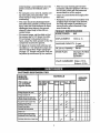
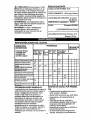
CUSTOMER
5W_0
Intake: .010 In.
Exhaust: .010 In.
RESPONSIBILITIES
SCHEDULE
SERVICE
RECORDS
Fill in dates as
you complete
regular service
As
',first 2 Each
Every Every Each
Neede¢ 10
! Hours Use
ChangeEngineOil Level
_
Change EngineOil
p,_
'Tigh_enaliscrew__d nuts
CheckTractionClutchCable
P#
Adjustment(S_ _b]e Adj)
_
Before
Season Storage
25
Hours Hours
p_.
_,
/J
p_'
P#'
_
Replace Spark Plug ............
.............. v _ ......../J
iCheck Drive Belts
Lubricate aft pivotpoinis
SERVICE
DATES
t
....
p,_
-
p_
p_
v"
iChe_ AugerClutchc_]e
Adjustment(See CabteAdj)
=
/,J
v_
i,, =
LubricateDiscDrivePlateZerk
-
_
...................
i i
14
, ....
p_'
GENERAL
RECOMMENDATIONS
SNOW THROWER
The-warranty on this snow thrower does not
cmier items that have been subjected to operator abuse or negligence_ To receive full
value from the warranty, the operator must
maintain the snow thrower as instructed in
this manual. The above chart is provided to
assist the operator in properly maintaining
the snow thrower.
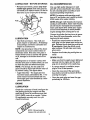
LUBRICATION
FIRST
or before storage.
To Lubricate:
°
Position speed
u
selector
lever in first gear.
Turn disc drive plate clockwise by hand
until grease zerk is clearly visible at front
center. See figure below.
USE
•
•
,
•
Check for any loose or damaged parts.
Tighten any loose fasteners.
Check and maintain the auger.
After each use, remove all snow and slush
off the snow thrower to prevent freezing of
auger or controls.
° Check controls to make sure they are
functioning properly.
• if any parts are worn or damaged, replace
immediately.
LUBRICATION
25 HOURS
Lubricate Disc Drive Plate eve ry twenty-five
(25) hours and atthe end of the season and/
Some adjustments will need to be made periodically to properly maintain your snow
thrower.
AFTER
- EVERY
Friction
Shaft
Wheel
Disc
(Require
No
LubricatiOn)
Friction
Wheel
Bearing
Piacecoinin gap
betweenfriction
wheel and disc drive
_/'plate
[
1
[_Grease
Zerk
CHART
Pointatwh
grease
shouldbe visible
• Place a coin or (a shim of equal thickness) between the rubber friction wheel
and disc drive plate to prevent rubber friction wheel contacting the drive disc.
- To grease zerk, use a hand grease gun,
lubricate with a Hi Temp EP Moly grease
See inset of second figure on this page.
DO NOT over fill or allow grease to come
in contact with the disc drive plate or friction wheel or damage will result. Fill zerk
only until grease becomes visible below
bearing assembly located under grease
zerk. See insert in figure above.
IMPORTANT: Remove coin and ensure that
a gap exists between friction wheel and disc
drive plate.
NOTE: Clean all excess grease found on
friction disc hub.
CAUTION: Do not allow grease to contact
friction wheel and disc drive plate.
Lubricate
Plate Zerk
with a Hi Temp EP Moly Grease°
t5
LU BRICATION
- BEFORE
STORAGE
OIL RECOMMENDATION
Remove both wheels, grease (any automotive type grease) both axles (see figure below) and replace wheels. Do this at
least once a year and/or prior to storage.
Only use high quality detergent oil rated
with API service classification SG, Select
the oil's viscosity grade according to your
expected operating temperature:
NOTE: For extreme cold operating conditions of 0° and below, use a partial synthetic
0W30 motor oil for easier starting.
Axle
NOTE: Although muJti-viscosity oils improve
starting in cold weather, these multi-viscosity
oils will result in increased oil consumption
when used above 32°F. Check your engine
oil level more frequently to avoid possible
engine damage from running low on oil.
Change the oil after first two hours of operation, every 25 hours thereafter, and at the
beginning of each season.
• Position the snow thrower so that the oil
drain plug is at the lowest point on the engine. Remove the oil drain plug and the oil
fill cap/dipstick. Drain the oil into a suitable container. Oil will drain more freely
when warm.
LUBRICATION
• Hex Shaft and Gears- Hex shaft and
gears require no lubrication. All bearings
and bushings are lifetime lubricated and
require no maintenance,
NOTE: Any greasing or oiling of the above
components can cause contamination of
the friction wheel, tf the disc drive plate or
friction wheel comes in contact with grease
or oil, damage to the friction wheel will resuit.
° Replace the oil drain plug and tightense..
curety,
SPARK PLUG
° Make sure that the spark plug is tightened
securely into the engine and the spark
plug wire is attached to the spark plug.
Should grease or oil come in contact with
the disc drive plate or friction wheel, be sure
to clean the plate and wheel thoroughly.
NOTE: For storage, the hex shaft and
gears should be wiped with 5W-30 motor oil
to prevent rusting. See figure above.
, Auger Gear Box - The auger gear box
has been factory lubricated for life. If for
some reason lubricant should leak out,
have auger gear case checked by a competent repairman.
• If a torque wrench is available, torque
plug to 18 to 23 foot pounds,
- Clean the area around the spark plug
base before removal to prevent dirt from
entering the engine.
• Clean the spark plug and reset the gap
periodically at ,030 inch,
ENGINE
LUBRICATION
Check the crankcase oil level (see figure be.,
low) before starting the engine and after
each five (5) hours of continuous use. Add
SoA,E. 5W30 motor oil as needed, Tighten
fil! cap/dipstick securely each time you
check the oil level.
[
•k_
-o_=_
NOTE: Oil level must be ,
between full and add mark
16
CAUTION;
Always
disconnect
• Loosen the carriage bolts and nuts securing the scraper bar to the auger housing.
the
spark plug wire and tie back away from
the plug before making any adjustments
or repairs.
Adjust the scraper
tion.
• Tighten the carriage bolts and nuts, making sure that the scraper bar is parallel
with the working surface.
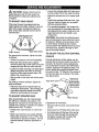
TO ADJUST SKID HEIGHT
This snow thrower is equipped w_h two
height adjustment skids, located on the outside of the auger housing (see figure below). These skids elevate the front of the
snow thrower.
• For extended operation, the scraper bar
may be reversed. If the scraper bar must
be replaced due to wear, remove the carriage bolts and nuts and install a new
scraper bar.
Nuts
CAUTION:
Be certain to maintain proper
ground clearance for your particular area to
be cleared. Objects such as gravel, rocks
or other debris, if struck by the impeller,
may be thrown with sufficient force to cause
personal injury, property damage or damage to the snow thrower.
O
Au
bar to the proper posi _
_rHousing
ust Skids
TO ADJUST THE CLUTCH CONTROL
For normal hard surfaces, adjust the skids
as follows:
CABLES
• Checktire
Periodic adjustment of the cables may be
required due to normal stretch and wear on
the belts° To check for correct adjustment,
the control lever must be in the full forward
pressure
(14 to 17 pounds).
• Place the extra shear bolts supplied
(found in parts bag) under each end of the
scraper bar near but not under the skid.
position, resting on the plastic bumper. The
control cables are correctly adjusted when
the center of the "Z" fitting is in the center of
the hole and there is no droop in the cable.
See figure below_
° Loosen the skid mounting nuts (see figure
above) and adjust the skids up to bring
the front of the snow thrower down. Retighten the mounting nuts°
° Set the skid on the other side at the same
Control Lever
height.
For rocky or uneven
skids as follows:
surfaces,
Auger Drive
adjust the
must be in full
forward position
"Z" Fitting
Raise the front of the snow thrower by
moving the skids down. This will help prevent rooks and other debris from being
picked up and thrown by the auger.
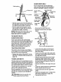
TO ADJUST
SCRAPER
plasticbumper)
whenchecking
BAR
per
After considerable
use, the metal scraper
bar will have a definite wear pattern. The
scraper bar may have to be returned to its
original lower setting to maintain the original
performance
level. To adjust:
° Position the snow thrower on a level surface.
If adjustment
• Remove
on end.
w
is necessary:
fuel from tank, and stand blower
Disconnect
the "Z" fitting from drive lever.
Pull rubber boot off the
Push the cable through
first figure on page 18)
threaded portion of the
Make sure both tires are equally inflated°
Proper tire pressure is 14 to 17 PSI. See
side of tire for maximum inflation. Do not
exceed sidewall maximum pressure on
tire.
17
top of the spring.
the spring (see
to expose the
cable.
AUGER
" Cable
DRIVE
BELT
if your snow thrower will not discharge
snow, and the auger drive belt (see figure
below) is damaged, replace it as follows:
spririg
end
Traction
Auger Drive Belt
Drive
Pulley
Traction
Locknut
Pulley
Drive Belt
Guide
(Left Hand)
(Right Hand)
Traction
Idler
- Hold the square end of the threaded portion with pliers and adjust the Iocknut in or
out until the excess slack is removed°
.
Augq
Pulley
Pull the cabJe back through the spring
and connect the cable. Do the same for
the other lever cable, if needed.
NOTE:
Whenever
the traction
" Disconnect the spark plug wire.
Remove the belt cover (see figure
below),
drive or au-
ger belts are adjusted or replaced,
cables will need to be adjusted.
N
the
TO ADJUST BELTS
AUGER DRIVE BELT
Belt Cover
if your snow thrower will not discharge
snow, check the control cable adjustment.
If
it is correct, then check the condition of the
auger drive belt. It may be loose or damaged° If it is damaged, replace it (see To
Replace Belts paragraph on page 18).
TRACTION
DRIVE
/
X 1/2
self-tapping Screw
BELT
• Loosen the belt guides (see first figure
this column) and pull away from the engine drive pulley.
The traction drive belt (see second figure
on this page) has constant spring pressure
and does not require adjustment.
- Loosen nut on the auger idler pulley (see
first figure, this column) and pull idler pulley away from the belt.
. Replace the traction drive belt if it is slipping (see To Replace Belts paragraph on
page 18).
° Remove top two botts that secure auger
housing to motor mount fi'arne. Loosen
bottom two bolts. Auger housing and motor mount frame will separate, hinged by
bottom two bolts.
TO REPLACE BELTS
The drive belts on this snow thrower are of
special construction and should be replaced
with original equipment belts available from
your nearest Sears Store or Service Center.
"Youwill need the assistance of a second
person while replacing the belts.
• Remove
ley.
,
Drain the gasoline from the fuel tank by removing the fuel line at the carburetor, Drain
the gas into a container and reinstall the
fuel line.
old belt from the auger drive pul-
install the original equipment replacement
belt in reverse order of removal.
• Position drive belt onto the auger drive
pulley.
• Adjust the belt guides (see To Adjust The
Belt Guides paragraph on page 19).
CAUTION:
Drain the gasoline outdoors, away from fire or flame.
s
18
Reinstall
the belt cover.
° Check clutch control cable adjustment,
see page 17.
• Reconnect spark plug wire.
TRACTION
DRIVE
Drive Pulley
Belt Guide
3/32 Inch
Belt Guide
f
(Left Hand)
3/32 Inch
BELT
If your snow thrower will not move forward,
check the traction drive belt (see second
figure on page 18) for wear (Check other
causes also in the Trouble Shooting Points
section). If the traction drive belt needs to
be replaced, proceed as follows:
• Disconnect the spark plug wire.
° Remove the belt cover (see last figure on
page 18).
,, Loosen the belt guides and pull away
from engine drive pulley (see first figure
on this page).
• Loosen nut on auger idler and pull auger
idler pulley away from belt. Note location
of idler pulley for later re-installation.
o Remove auger drive belt from engine pulley.
° Pull the idler pulley away from the drive
be_t, allowing belt to be positioned onto
engine pulley.
° Release idler pulley. Ensure idler pulley is
properly engaged with belt.
° Reinstall auger drive belt.
TO ADJUST THE FRICTION WHEEL
If the snow thrower will not move forward,
you need to check the traction drive belt, the
traction drive cable or the friction wheel, if
the friction wheel is damaged, it will need to
be replaced (see the To Replace Friction
Wheel paragraph on page 20). If the friction
wheel is not worn, check the adjustment, as
follows:
° Disconnect
the spark plug wire.
• Drain the gasoline
• Stand
end.
from the gas tank.
snow thrower
on the auger housing
° Remove the bottom panel (see figure be-
low).
Motor Mount Frame
Remove Top Bolts
• Adjust belt guides (see To Adjust The
Belt Guides paragraph on page 19).
Adjust idler on auger belt.
Reinstall the belt cover°
°
o
o
Reconnect
Panel
the spark plug wire.
Auger
Housing
TO ADJUST THE BELT GUIDES
After you replace the traction or auger drive
belt, you need to adjust one or both of the
belt guides. Proceed as follows:
o Disconnect the spark plug wire.
° Remove the belt cover (See last figure on
page 18).
• Engage the auger drive clutch lever.
° Measure the distance between the belt
guides and the belt (See next figure). The
distance should be 3/32" for each guide.
Loosen Bottom
(each side)
o
°
Position the shifter lever in first (1) gear.
Note the position of the friction wheel on
the disc drive plate. The right outer side of
the disc drive plate should be 3" from the
center of the friction wheel (See figure be-
low).
Shaft
° tf adjustment is necessary, loosen the
belt guide mounting bolts. Move the belt
guides to the correct position. Tighten the
mounting bolts.
• Reinstall the belt cover.
\
\
, Reconnect the spark plug wire.
>
_'_
\
19
<
If adjustment
is necessary:
Remove right side bearing plate. Leave
hex shaft in original position.
Remove friction wheel from hub. Slip friction wheel off hex shaft towards right side.
See figure below.
• Loosen bolts in speed selector lever (see
figure below).
Speed SelectorLever
Friction Wheel
====------_--__L'_Bolts
Lockwasher
to be
Shaft
%_-' _
TO REPLACE
FRICTION
loosened
Bolt
WHEEL
Nut Lockwasher
If the snow thrower will not move forward,
and the friction wheel is worn or damaged,
you need to replace it as follows: (First allow
the engine to cool).
TO REPLACE
AUGER
SHEAR
BOLT
The augers are secured to the auger shaft
with special bolts (see figure below) that are
designed to break (to protect the machine) if
an object becomes lodged in the auger
housing, Use of a harder bolt wilt destroy the
protection provided by the shear bolt.
° Drain the gasoline from the fuel tank.
° Drain the fuel in a container and reinstall
the fuel line.
° Disconnect the spark plug wire.
• Stand the snow thrower up on the auger
housing end (see figure below).
Friction
Bearing
Plate Bolts
IMPORTANT:
To ensure safety and performance levels, only originalequipment shear
bolts shouldbe used°When replacingshear
bolts, be sure to replace shear bolt spacers.
To replace a broken shear bolt, proceed as
follows:
Plate
Fasteners
Bolts,
- Move the throttle to t_t (STOP) and turn
off all controls.
Disconnect the spark plug wire. Be sure
all moving parts have stopped.
Lubricate the auger shaft by squirting
Lubriplate or a fiber impregnated grease
into the shear bolt hole in the auger shaft.
Then rotate the auger to distribute the oil
in the shaft.
- Remove the bottom panel (see second
figure on page 19).
- Align the hole in the auger with the hole in
the auger shaft. Install the new shear bolt
and shear bolt spacer provided.
° Reconnect the spark plug wire.
o Remove the three (3) fasteners securing
the friction wheel to the hub (see second
figure above).
- Remove the four bolts securing the bearing plates (both sides), (see second figure above).
20
TO ADJUST CARBURETOR
IMPORTANT:
Never tamper with the engine governor; which is factory set for
proper engine speed. Overspeeding
the
engine above the factory high speed setting
can be dangerous,
tf you think the enginegoverned high speed needs adjusting, contact your nearest Sears Service Center,
which has the proper equipment and experience to make any necessary adjustments.
The carburetor (see figure below) has been
pre-set at the factory and readjustment
should not be necessary. However, if the
carburetor does need to be adjusted, proceed as follows:
• Close the high speed adjusting screw by
hand.
TO ADJUST OR REPLACE
Carburetor
SPARK PLUG
if you have difficulty starting your snow
thrower, you may need to adjust or replace
the spark plug. Follow the instructions betow.
Idle Adjusting Screw
finger tight only)
Replace the spark plug if the electrodes
pitted or burned or if the porcelain is
cracked.
Carburetor Bowl
High Speed Adjusting Screw
(Close finger tight only)
-
Clean the spark plug by carefully scraping
the electrodes (do not sand blast or use a
wire brush).
1-1/2turns.
Close the idte adjusting
Do not over-tighten.
• Then open it 1-1/4to
• Start the engine
• Set the throttle
screw by hand.
Be sure the spark plug is clean and free
of foreign material. Check the electrodes
gap (see figure below) with a wire feeler
gauge and reset the gap to .030 inch if
necessary.
1-1/2turns_
and let it warm up.
control
to '_
(FAST).
are
TO ADJUST:
Do not over-tighten.
, Then open it 1-1/4to
THE
Ad-
just the high speed adjusting screw in until the engine speed or sound alters. Adjust the screw out until the engine speed
sound alters. Note the difference between
the two limits and set the screw in the
middle of the range.
TO REPLACE:
,, Let the engine run undisturbed for 30
seconds after each setting to allow the
engine to react to the previous adjustment.
- if you need a new spark ptug, use only
the proper replacement spark plug (See
page 14).
• Set the gap to .030.
° Before installing the spark ptug, coat its
threads lightly with oil or grease to insure
easy removal.
. Tighten the plug firmly into the engine.
- If a torque wrench is available, torque the
plug to18 to 23 ft_- tbs,
Set the throttle control to _
(SLOW).
Adjust the idle adjusting screw in until the
engine speed drops, then adjust the
screw out until the engine speed drops.
Note the difference between the two limits and set the screw in the middle of the
range.
If the engine tends to stall under load or
does not accelerate from low speed to
high speed properly, adjust the high
speed screw out in 1/8 turn increments
until the problem is resolved. Let the engine run for 30 seconds between settings.
21
Z_CAUTION:
= If you do not want to remove gasoline,
Never store your snow
a
fuel stabilizer (such as Craftsman Fuel
Stabilizer No. 33500) may be added to
any gasoline left in the tank to minimize
gum deposits and acids, tf the tank is almost empty, mix stabili7er with fresh
gasoline in a separate Container and add
some to the tank.
thrower
indoors or in an enclosed, poorly
ventilated area if gasoline remains in the
tank. fumes may reach an open flame,
spark or pilot light from a furnace, water
heater, clothes dryer, cigarette, etc.
To prevent engine damage (if snowthrower is
not used for more than 30 days) follow the
steps below.
Always follow instructionson stabilizer container. Then run engine at least 10 minutes
after stabilizer is added to al!ow mixture to
reach carburetor. Store snow thrower in a
safe place. See Warning above.
SNOW THROWER STORAGE
o Thoroughly clean the snow thrower.
- Lubricate all lubrication points (See the
Maintenance section on pages 14-16).
, Be sure that all nuts, bolts and screws are
securely fastened.
Inspect all visible moving parts for damage, breakage and wear,,
Replace if necessary.
You can keep your engine In good operating
condition during storage by:
• Changing oil (See page 16).
• Lubricating the piston/cylinder area. This
can be done by first removing the spark
plug and squirting a few drops of clean
engine oi! into the spark plug hole. Then
cover the spark plug hole with a rag to
absorb oil spray. Next, rotate the engine
by putling the starter rope fully out two or
three times. Finally, reinstall spark plug
and attach spark plug wire.
° Touch up all rusted or chipped paint surfaces; sand lightly before painting.
• Coverthe
bare metal parts of the blower
housing auger and the impeller with rust
preventative,
such as a spray lubricant.
NOTE: A yearly checkup or tune-up by a
Sears Service Center is a good way to insure that your snow thrower will provide
maximum performance
for the next season.
OTHER
ENGINE STORAGE
-
Gasoline must be removed or treated to prevent gum deposits from forming ih the tank,
filter, hose, and carburetor during storage.
Also during storage, alcohol blended gasoline that uses ethanol or methanol (sometimes called gasohol) attracts water. It acts
on the gasoline to form acids which damage
the engine.
If possible, store your snow thrower indoors and cover it to give protection from
dust and dirt.
• if the machine must be stored outdoors,
block up the snow thrower to be sure the
entire machine is off the ground.
• Cover the snow thrower with a suitable
protective cover that does not retain
moisture. Do not use plastic or vinyl.
- To remove gasoline, run the engine until
the tank is empty and the engine stops.
Then drain remaining gasoline from carburetor by pressing upward on bowl drain
located on the bottom of carburetor (see
first figure on page 2t).
IMPORTANT:
while engine
warm,
22
Never cover snow thrower
and exhaust
areas are still
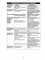
TROUBLE
"
Difficult starting
i
CAUSE
Defective spark plug
Water or dirt in fuel system
CORRECTION
Replace defective plug
Use carburetor bowl drain to
flush and refill with fresh fuel
Engtne runs erratically
Blocked fuel line or low on fuel
Clean fuel line; check fuel supply; add fresh gasoline (gasoline/oil mixture ff 2-cycle engine)
Engine stalls
Unit Rfnning on CHOKE
Move choke lever to OFF position
Engine runs erratically;
Water 0r_
Use carburetor bowl drain to
flush and refill with fresh fuel
in fuel system
or
Loss of power
Carburetor out of adjustment
Adjust carburetor
Excessive
vibration
Loose parts; damaged impeller
Stop engine immediately and
disconnect spark plug wire.
Tighten all bolts and make all
necessary repairs, tf vibration
continues, have the unit serviced by a Sears service repair..
man
Units fails to
propel itself
Drive belt loose or damaged
Replace
Incorrect adjustment of auger control cable
Adjust traction drive cable
Worn or damaged friction wheel
Repair friction wheel
Auger drive belt loose or damaged
Replace auger belt
Auger control cable not adjusted
correctly
Adjust
Shear bolt broken
Discharge chute clogged
Replace shear bolt,
Unit fails to
discharge snow
drive belt
auger control
cable
Stop engine immediately and
disconnect spark plug wire.
Clean discharge chute and inside of auger housing.
Foreign object lodged in auger
23
Stop engine immediately and disconnect spark plug wire. Remove
object from auger.
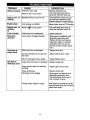
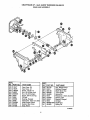
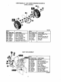
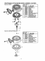
CRAFTSMAN
22" - 5H.P. snow THROWER
ELECTRIC START ASSEMBLY
REF
NO.
PART NO.
6
33o783
7
8
9
6216
6217
6219
760015
i
536.886122
PART NAME
M0toi:,Electric Starter
Screw, 114-20x.50
Screw #6-32x2.50
Cord, Starter Motor
Owner's Manual Eng/Sp
319051B
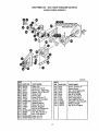
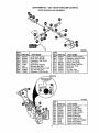
ENGINE ASSEMBLY
L,t_.
ENGINE MOUNTS TO FRONT HOLES
ON THE FRAME
!
\
326928D
REF
NO.
PART NO,
PART NAME
REF,
NO. PART NO.
,,l i,i .,.
10
ENGINE
12
13
31
33
34
41
43
44
5t
710024
120638
3949
120638
578733
3949
120638
578733
579855
Model 143.975001
(See Engine pages)
Screw, 5/16-18
Washer, Hvspttk
Guide, Rod Belt RH
Washer, Hvsptlk
Screw, 5/!6-24x_625
Guide, Rod Belt LH
Washer, Hvsptlk
Screw, 5/16-24x.625
Washer, Crankshaft
Note: Always use original equipment parts, Use of
service/replacement parts other than originai parts
may voidyour warranty,.
24
52
53
57
58
59
60
63
67
68
69
579861
579854
579932
73840
586251
586253
581264
313826
120382
39573
PART NAME
i
Flatwasher o765x1.12x.06
Pulley Half V3L
Belt, V 3L 33.13Lg
Flatwasher .765xl. 12xo06
Spacer, Sleeve
Pulley, Engine
Belt, V 4L
Flatwasher
Washer, Regsptlk
Screw, 3/8-24xl o00
All unnumbered items are
interchangeable with opposite side
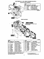
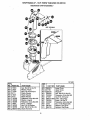
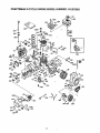
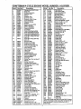
CRAFTSMAN22"- 5H.P.SNOWTHROWER536.886122
FRAMEASSEMBLY
339392(3
REF.
NO. PART
80
88
90
91
100
103
104
105
106
107
108
i09
110
112
NO.
340578-854
35497
583031-830
310169
336657
340604
335587
41529
340682
340579
340373
340869
180124
313843
REF°
NO, PART NO.
PART NAME
i i,,15
41529
!133 313854
Frame Assembly
Screw, 5/16-18x.50 Tap.
Panel, Bottom
Screw, 1/4-20x.63 Tap,
Plate, Clutch Arm Mtg..
Arm-Clutch
Bolt, 3/8-16 Shoulder
Nut, 3/8-16 Hxctrikjam
Clip, Cable
Bracket,Compact CableMtg
Cable, Auger Clutch Cont.
Shield, Cable
Screw, 3/8-16xl .25
Idler Pulley
! 14o 579872
!141
180077
1142 73795
ii 143 579865
144 71038
i 145 313854
' 146 18O124
313843
149 41529
16o 580772
161 310169
162 120392
_,,,,,,:
25
PART NAME
318-16 Hxctdkjam
Spring, Tension Return
Lever, Idler Arm Traction
Screw, 5/16-18x.75
Ratwasher ..328x..125x.075
Bushing, Idler Lever
Nut, 5/16-18 HexcLrlk
Idler Spring
Screw, 3/8-16xl .25
Idler Pulley
Nut, 3/8-16 Hexctdkjam
Belt Cover
Screw, 1/4_20x_63Tap
Flatwasher °28lx.63xo06,_
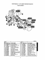
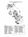
CRAFTSMAN
22" - 5H+P. SNOW THROWER 536.886122
DRIVE ASSEMBLY
\
@
REF,
NO. PART NO.
579941
313853
137185
313919
579937
11871
1502
_83163.-830
583206
583155
85501
71074
73811
580969
43846
58097O
580961
580965
1084
120.380
180020
334163
313995 I
REF.I
PART NAME
'N0,
231
232
235
240
243
244
245
246
247
249
250
255
256
257
270
271
275
276
277
278
Lever, Shaft Tract. Clutch
Bearing, Flanged
Cotter Pin +125xl +00
Return Spring
Lever, Spring Trac Cl+
Screw, 1/4-20x+63
Nut, 1/4-20 Reghexctrtk
Disc, Assy Fric Wheel
Zer, Grease
Shaft, Hex Traction
Bearing, Trunion
Bearing, Trunion
Ring, Retaining
Ratwasher .680x1+12x.060
Bearing, Ball
Key, Square
Pulley, V3L
Wave Washer
Flatwasher +281xl +00x.063
Washer, Regsptik
Screw, 1/4-20x+75
Bearing & Retainer Assy+
26
PART NO.
35497
120638
579858
579897
462
71074
337029
313883
11871
303008
579858
334163
35497
120638
334163
35497
579893
334163
35497
579867
PART NAME
Screw, 5/i6-18x150 Tap+
Washer, Hvsptlk
Washer, Sp. +502x+75x.0605
Hex, Assy #.40-8
Ring, Retex
Flatwasher .53x 1.00x.063
Beating, Trunion CI. Releas_
Wheel Assy. Friction Disc
Screw, 1/4-20x+63
Nut, 1/4-20 HexKeps
Washer, Sp .502x+75x.0605
Bearing & Retainer Assy+
Screw, 5/16-18x_50 Tap+
Washer, Hvsptlk
Bearing & Retainer Assy+
Screw, 5/16-18x.50 Tap.
Jack Assy #41-36T&ST
Bearing & Retainer+Assy
Screw, 5/16-18x.50 Tap.
Chain, Roller #42
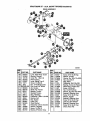
CRAFTSMAN
..........................
REF,
NO. PART NO,
300
10577
301 10576
303
180020
304 46931
305 303008
306 9344
310 9566
31 t 50304
3t2
9346
313 340284
314 51279
1315 51405
22" - 5H.P. SNOW THROWER
GEAR CASE ASSEMBLY
536.886122
,j,, ,,j,, ,
REF.
NO. PART NO.
PART NAME ....
PART NAME
,,,,H,i
Gear Case, RH
Gear Case, LH
Screw, 1/4-20x.75
Nut, 114-20 Mac-Lock
Nut, 1/4-20 Hexkeps
Screw, 3/8-16x.50 Tap°
Oil Sea!
Bearing, Flanged
Flatwasher _752x1,24x_,093
Shaft, Auger Output
Gasket, Gear Case
Gear Worm
316
320
321
322
!323
324
'325
Z326
327
340
34t
431787
50221
583125
580295
454565
9346
313828
50304
9566
585598_830
454565
Key, Woodruff #61
Bearfng, Flanged
Shaft, Worm Imp
Thrust Collar
Spring Pin
Flatwasher ,,752x1,24x ,093
Bearing, Roll
Bearing, Flanged
Oil Seal
Impel Assy
Spring Pin
313996B
27
CRAFTSMAN
22" - 5H. P. SNOW THROWER 536.886122
AUGER HOUSING ASSEMBLY
500 IS A WELDMENT AND
INCLUDES TWO SIDE PANELS
@
;3,39972C
'REF
NO. PART NO.
48O
481
i482
485
490
491
493
499
500
502
504
505
506
5t0
511
514
520
521
S ta4 ....
577400
71371
334514
582960
43846
180077
710026
340967-854
311087
71003
120382
1499
581395-830
323825
51335
340525-830
340520-830
PART NAME
PART NO.
NO___L.
522 9524
523 3943
524 1502
525 9517
8619
526
527 9357
540
1161
541 70993
542
120393
543
120638
544
120376
Pulley, V4L
Screw 5!16-18x.63
Square Key+ 18Sqx+88Lg
Spacer, Slev +676xlx+53
Retainer, Ball
Bearing, Ball
Screw, 5116-18x+75
Nut, 5/16-t8 Hexwdfllk
Housing Assy+
Ratchet Fastener'
Screw, 3/8-16x+75
Washer, Regsptlk
Nut, 3/8-16 Reghexctrlk
Blade, Scraper 24"
Catr+ Bolt, 1t4-20x+75
Nut, 1/4+20 Whiz-lk
Auger Assy RH
Auger' Assy LH
_
28
PART NAME
Screw, 114+20xl+75
Spacer Sleeve
Nut, 1/4-20 Reghexctdk
Flanged Bearing
Nut, 5116-18 Wdfl
Screw, 5/16.-18x+75
Skid, Height Adjust
Oarr. Bolt 5f16-18x+75
FlaP_asher .344x°69x+065
Washer, Hvspflk
Nut, 5/!6-18 Reghex
CRAFTSMAN
22" - 5H.P. SNOW THROWER 536.886122
DISCHARGE CHUTE ASS EMBLY
337160D
REF.
NO.
PART NO.
582
583
584
588
592
593
594
595
596
597
598
599
600
cart...............
70993
Bolt 5/16-18xo75
12021
Washer, Plastic
71038
Nut, 5116-18 hexnylon
6711
Plastic Washer
12021
Plastic Washer
6711
Plastic Washer
120393
Flatwasher .344x.69x065
120638
Washer, Hvsptlk
120393
Flatwasher o344x.69x.065
13527
Knob, T 2 Blade
120376
Nut, 5!16-18 Reghex
126358
Carro Bolt 5/i 6-18x 1.,00
760016-.830 Chute Assembly
__=
REF.
NO.
PART NO. PART NAME
S00-1 585501
Lower Chute
500-2 11780
Upper Chute
PART NAME
_00-3
_01
302
303
306
307
308
309
310
311
29
305216
586280
120393
71.038
585214-830
180020
120392
1502
337227
585193
Hinge Pin
Carr. Bolt 5t16_18xl.00
Flatwasher .344xo69x.065
Nut, 51t6-18 Hexnyl
Collar, Chute RecL
Screw, 1/4-20xo75
Ftatwasher .281x,63xo065
Nut, 1/4-20 Reghexctdk
Retainer, Ring Inner
Retainer, Ring Outer
CRAFTSMAN
22"- 5H.P. SNOW THROWER 536.886122
HANDLE ASSEMBLY
339622B
iREFI
NO, PART NO.
720
724
725
i726
727
728
730
731
733
_,734
i739
741
743
9552-830
11234
120393
120638
120376
11261
334195
334195
1058
353.5
4049
1579
579869
ii
PART NAME
Upper Ha.nd{e
Screw, 5/16-18x2_75
Flatwasher ._344x,69x_065
Washer', Hvsptlk
Nut, 5/16-18 Reghex
Stop, Red Plastic
Kit for RH Handle Assy
Kit for LH Handle Assy,
Pivot Pin
Nut, Push On
Bumper, Rect.
Cable, Clutch
Spr_ng,Tension
NO. I
744 I
745 i
746 I
750 I
7511
752 !
753 I
754 I
755 I
756 I
757 !
L
...............
PART NO.
i
PART NAME
ill
1673
1502
308146
339541-830
180079
120638
120376
309436
337407-830
180087
56021
Spring, Auger Clutch
Nut, 1/4-20 Reghexctdk
Boot, Clutch Spdng
Handle, Lower
Screw 5/16-18x 1_00
Washer, Hvsptlk
Nut, 5/16-18 Reghex
Pushnut, 5/16
Brkt, Gear Selector
Screw, 5/16-18x2.00
Screw, 114-14x.75 Tap.
CRAFTSMAN
22" - 5H.P.
SNOW
THROWER
536.886122
WHEEL ASSEMBLY
\
318542E
REF.
NO.
650
6-52
653
654
655
656
PART NO.
580883
583012
73839
1502
581730
579867
671173840
REF.
NO. PART NO.
PART NAME
6731585591
Shaft, Axle Wheel/mid
Sprkt & Hub Assy.
Screw 14-20x2o25
Nut, 1/4-20 Reghxctrtk
Bearing, Flanged
Chain, Roller #42x40P
Flatwasher o765x t. 12xO6
675
676
677
678
! 318504
! 577015
11502
1239
PART NAME
Bushing, Wheel 4"Lg
Tire & Rim
Screw Shr 1/4-20xl.75
Nut, 1/4_20 Reghxct.rlk
Ring, Ret.
Pin, Klik
679 173842
SHIFT YOKE ASSEMBLY
REF.
NO. PART NO,
790
791
792
795
796
800
801
8O2
811
812
813
i581631-830
51332
1502
318486
!304438
i581630
51332
1502
579944
581795
1499
PART NAME
Screw, 1t4_20x.63
Nut, 1/4-20 Reghexctrlk
Nut, 1/2-13 Hexjam
Knob, Shift
Lever, Spring
Screw, 1/4-20xo63
Nut, 1/4-20 Reghexctdk
Bearing, Flanged
Rod, Assy Yoke
Nut, 3/8-16 Reghexctdk
319053C
31
CRAFTSMAN 22"- 5H.P. SNOW THROWER 536.886122
CHUTE CONTROL ROD ASSEMBLY
L
\\
•
334215C
!REF.!
NO.
PART NO.
585426
t850
;854 307399
i855
3O9312
1856 578159
L860 = 71457
148
i861
862
308145
i863
124829
[864.
120394
.
,i
i
iR EF.I
N0.1 PART NO.
PART NAM E
Crank Assy, W/yoke
Chute Crank Handle
Flatwasher, .39x.70x.35
Ring, Ret. E.
Eye Bolt 3/8-16x5.00
Grommet Eye Bolt
Boot, Eye Bolt Chute Crank
Nut, 3/8-16 Hexjam
Flatwasher'.406x.81x.065 i
uL,_
865 I 309344
!866 i 120394
1867 i 71O46
87O ! 585195
1871 i 585196
872 ! 578063
873 I 578309
18741578060
579493
PART NAME
Adapter, Boot to Hanclle
Flatwasher .406x31x.065
Nut, 318-16 Hexnyl
Bracket, Worm Mtg
Worm, Gear Chute Rot
Block Univ. Pivot
Clevis Pin
Pin, Univ. Joint
Cotter Pin 06x50
,i,i
DECALS
314OO5E
REF.!
NO.
PART NO.
822 i 302487
823i7014I
824
313892
825 ] 302922
826 _ 308766
827 !334151
828 i 337443
829 !3902
830 !3903
831
340047
32
_ .
PART NAME
Decal,
Decal,
Decal,
Decal,
Decal,
Decal,
Decal,
Decal,
Decal,
Decal,
9" Impeller
Danger Auger
Danger Chute
Danger English
Craftsman
El Start 5/22
Danger Chute
Traction Dr_ Engage
Gear Selector
Gear Selector
CRAFTSMAN
4-CYCLE ENGINE MODEL NUMBER: 143.975001
307/O
41
!
396
_A"
170,
274
365,
384,,
262
260
184/<_
370C
P_
S
'' 185181
-
,%
285
33
-_,
93p,/_/
287 390
,370G
_
370K
f
I
CRAFTSMAN
Psrt No,
1
2
4
5
14
15
16
17
18
19
20
25
25A
26
26A
30
40
40
4O
4t
41
36469A
26727
30968
30969
28277
31334
31510
31335
650.548
31426
32600
36552
35883
41
36072
42
42
42
43
36076
36077
45
46
48
49
50
60
61
62
63
64
64A
65
69
70
72
75
80
81
82
83
86
89
90
92
93
100
101
102
103
110
! 10A
!19
120
125
125
126
126
650802
650926
34740
36073
36074
36075
36070
36071
36078
20381
32875
32610A
27241
32654
33158
29745
3_126
65076o
28545
30063
8345
65O 128
27677A
34674C
27642
27897
30574A
30590A
3,3591
30588A
650488
610981
611199
650815
650816
34443A
610118
650872
651007
35557
35285
364
36441
36471
36472
32644A
32645A
127
650691
130
6021A
130A 650694A
130B 650818
135 35395
4-CYCLE ENGINE MODEL NUMBER: 143.975001
Part No.
Description
_g'O.............
Cylinder (lncl 2;20.72,125)
Dowel Pin
oil Draln Extension
Extension Cap
Washer
Governor Rod
Governor Lever
Governor Lever CIamp
Screw 8-32x5/16"
Extension Spring
Oil Seal
Blower Housing Baffle
Baffle Extension
Screw t!4-20x5/8"
Screw 8-32x21164"
Crankshaft
Piston,Pin,&Ring Set(Std)
Piston,Pin,&Ring Set(.010")
Ptston,Pin,&Ring Set(.020")
Piston&Pin Assy(Std(tncl.43)
Piston&Pin Assy(,010" OS)
(ind. 43)
Piston&Pin Assy(.020" OS)
(Incl. 43)
Ring Set (Std)
Ring Set (,010" OS)
Ring Set (,020 "OS)
Piston Pin Retaining Ring
Connecting Rod A_y
(Incl. 46 & 49)
Connecting Rod Bolt
Valve Lifter
Oil Dipper
Camshaft (BCR)
Blower Hsing Extension
Grommet Mtg Bracket
Screw 8.32x3/8"
Grommet
Screw Torx T-30 1/4-20x112"
Washer
Screw 10-24xlt2"
Cylinder Cover Gasket
Cylinder Cover (tnc175-83)
OI! Drain Plug
Oil Seal
Governor Shaft
Washer
Governor Gear Assy.(tnct 81)
Governor Spool
Screw. 1/4-20x1-1/4"
Flywheel Key
Flywheel (w/ring gear)
BelleviIle Washer
Flywheel Nut
Solid State ignition
Spark Plug Cover
Solid State Mting Stud
Screw Torx T-15 10-24x15!16
Ground Wire
Ground Wire
Cylinder Head Gasket
Cylinder Head (Ind !31)
Exhaust Valve (std)!lnc1151)
Exhaust Valve(I/32 OS)
(Inc!. 151)
Intake Valve (std}(tncL 151)
Intake Valve (1/32" OS)
(Incl. i51 )
Washer
Screw 5f16-18x1-1/2"
Screw 5116-18 x 2`°
Screw 5/16,-18 x 1-1/2"
Resistor Spark Plug(R J19LM)
151
169
170
171
172
173
174
178
181
182
183
184
185
186
200
203
204
2O6
209
209A
215
219
31673
27234A
27666
31410
34146
35350
30200
29752
650870
6201
34583
26756
336gl
32698
33858A
31342
650549
i610973
!650139
;30322
35440
,34582
220
35438
222
28820
223
650664
224
33673A
26O
35656A
650737
262
267
34212
268
30200
274
33670A
275
35771
650327
277
285
36467A
287
650926
30705
290
292
26460
298
650665
300
35584
35355
301
305
35554
307
35499
3O8
355-39
310
35556
313
34080
35593
328
610973
329
335
35072
338
650257
340
36247
342
30063
342A 650675
345
33344
350
570682
351
32180C
355
590574
364
33333
365
650735
370A
36261
370C
36501
370D
35878
370G
35282
36695
370K
380
632107A
390
590707
396
33290D
Description
VaJveSpring
Valve SpringCap
Valve CoverGasket
BreatherBody
BreatherElement
Valve Cover
BreatherTube
Screw I0-24 x 9t16"
Nut & LockWasher 1/4-28"
Screw1/4-20 x 1-11/16"
Screw114-28x 7/8"
ChokeBracket
CarburetorTo Intake PineGskt
IntakePipe
GovernorLink
ControlBkt(IncL 203-209A)
CompressionSpring
Screw5-40x7/16"
Terminal
Screw8-32 x 3/4"
l_o_nut
8-32
Control Knob
Choke Rod
ChokeKnob
Screw10-32 x 1/2_
Screw 1t4-20 x 1-19/32"
Intake Pipe Gasket
BlowerHousing
Screw 1/4-20 x 112"
Hold DownBracket
Screw 10-24 x 9/16"
ExhaustGasket
Muffler(incL274)
Screw 114-20x 2-27164"
StarterCup
Screw8_32x21164"
Fuel Une
Fuel Une Clamp
Screw 114-15x 3/4"
Fuel Tank (ind 292 & 30!)
Fuel Cap
Oil Fill Tube
"(3" Ring
FillTube Clip
Dipstick
Spacer
Ignition Key
Terminal
Carburetor Cover
Screw8-32 x 5/16"
Fuel Tank Bracket
ScrewTorx T-30 114-20xlt2"
Washer
Heat Baffle
Primer Assy
Primer Line
Starter Handle(Mitten Grip)
Carburetor Cover Bracket
Screw 10-24 x 3/8"
LubricationDecal
PrimerDecal
WarningDeca!
ChokeDecal
StarterDecal
Carburetor(incL 184)
RewindStarter
ElectdcStarterMotor(110 Volt}
(Optional)
Gasket Set
400
36444
This engine could have been built with 590742 starter,
Refer to the design of the rope pulley strength ribs for
)art identification. Individual starter parts do not
interchange.
34
CRAFTSMAN
4-CYCLE
ENGINE MODEL NUMBER: 143.975001
Starter No. 590707
REF_ PART
NO.,,!,, NO.
i0
1590707
11 1590599A
PART NAME
R_oiI sta_er
....
spring Pin (Incl. 4)
! 2 159o6oo Washer
Retainer
13
1590696
i 4 159o6o1 Washer
I 5 1590697 Brake Spring
16
J590698
Starter Dog
! 7. 1590699
Dog_Spring
I B _"15907o9Pulley & Rewind Sprg Assy
Starter Housing Assy
11t
159.0708
Starter Rope
t 12 1590535 (Length 98"x9/64" dia)
Mitten Grip_Handle(not
included with starter)
L__.J 590574
12
13
7-'_
11_7
O
4
O
R
Starter No. 590742(OPTIONAL)
U
REF. PART
NO. NO.
,u
l i|
590742
590740
t2
13
_8
._
j..=-7
35
8
tl
12
590616
590617
590645A
590647
590535
13
590574
14
590741
PART NAME
Rewind Starter
Retainer
Starter Dog
Dog Spring
Pulley, & Rewind Spring
Starter Hsing Assy
Starter Rope
(Length 98"x9/64" dial)
Mitten Grip Handle
(Not included wlstarter)
Locking Tab
CRAFTSMAN
4-CYCLE ENGINE MODEL NUMBER: 143.975001
Carburetor No.632107A
2
_5
t
I
1
t
I
27
i
I
REF:I
P I
REF. PART
NO.
0
1
2
16
7
10
14
i15
16
17
18
20
21
22
23
25
27
NO.
PART,NAME
632107A Carburetor (ind 184 on engine)
631615
Throttle Shaft & Lever Ass'y.
631767
Throttle Return Spring
Throtter Shutter
631036
Shutter Screw
650506
632108
Choke Shaft & Lever Assy
Choke Shutter
631815
630735
Choke Positioning Spring
631807
Fuel Fitting
650417
Throttle Crack Screw/Idle
Speed Screw
630766
Tension Spring
idle Mixture Screw
631838
630766
Tension Spring
630739
idle Mixture Screw Washer
630740
Idle Mixture Screw "O" Ring631951
Roat Bowl Assy (lnc132&33)
631024
Roat Shaft
O. J NO,
I
PART NAME
.......
1632019 !Float
9
0
! Float Bowl "O" Ring
_tnlet Needle, Seat & Clip
i(Inc131)
I SpringClip
I BowlDrain Assembly
i Drain Plunger Gasket
I Main Adj. Screw Assy(ind 41-44)
I HighSpeed Mixture Screw "O"
Rin
/
!
I Washer
143
/
144
147
148
60
1630738
|
127110
|630748
1631027
31840
I High Speed Mixture Screw
I Tension Spring
I Bowl Nut Washer
I Welch Rug, Idle Mixture Well
I Welch Plug, Atmospheric Vent
Repair Kit
t
2
3
0
1
36
........
1631028
1631021
!
]631022
|27136A
127554
131839
1630740
CRAFTSMAN 4-CYCLE ENGINE MODEL NUMBER: 143.975001
Starter Motor No. 33290D
is
2_
\,
\
10
I
REF.
PART
NO.
C)
t
2
3
14
5
6
7
8
9
10A
13
14
15
NO.
33290Di
31749
33522
33769
33524
35911
35461
35450
35912
35459A
35452A
590500
33441
35453
16A
24
25
27A
30
31
35454
35462
35456
650819
32450B
650759
*
PART NAME
Electric Sta_er (110 Volt)
Retainer Ring
Spring Retainer
Anti-drift Spring
Nut and Gear
Thrust Washer
Drive End Cap Assy (Incl 7)
"O" Ring
Armature
Housing Assembly
Brush & Spring Card Assy.
Thrust Washer
Ground Screw
Commutator End Cap Assy.
(Incl 7)
Switch Box Assy (tnct 21 )
Case Bolt
Grounding Screw
Screw 6-32 x 2-1/2"
Extension Cord 10"6")
Screw Torx T-30 1/4-20x23/32"
37
REMOVEDORA DE NIEVE
Operacion
Mantemiento
Servicio y Ajustes
Almacenamiento
So]ucion de prob[emas
Pedido/Servicio de Piezas
Tabla de contenidos
38
Garantia
38
Reglas de seguridad
38-40
Contenido del paquete con articulos de
ferreteria
41
Montaje
42-45
GARANTIA
LIMITADA
CRAFTSMAN
DOS
:{E LA REMOVEDORA
45-52
52-54
55-60
61
62
64
DE NIEVE
Durante dos aSos a partir de la fecha de compra, cuando esta Rernovedora de nieve
Craftsman sea manten[dad, lubricada y afinada de acuaredo con las instrucc[ones en el
manual del propietario, SEARS reparar_., sin recargo alguno, cualquier defecto en
materiales y mano de obr_
Siesta Removedora de nieve Craftsman se usa para prop6sltos comerciales o de
arrendamiento, esta garantia es v&lida durante 90 dfas a partir de la fecha de compra.
Esta garantfa no cubre 1osiguiente:
• Elementos fungibles los cuales se gastan durante el uso normal, tales como bujfas,
correas de transmisi6n y clavijas de seguro por esfuerzo cortante.
- Reparaciones necesarias debido al abuso o negligencia del operador, incluyendo
cig0efales doblados y la falta de mantenimiento del equipo de acuerdo con fas
instrucciones contenidas en el manual det proptetario.
EL SERVlCIO DE GARANTIA SE PUEDE OBTENER AL DEVOLVER LA REMOVEDORA
DE NIEVE CRAFTSMAN AL CENTRO/DEPARTAMENTO
DE SERVlCIO SEARS MAS
CERCANO EN LOS ESTADOS UNIDOS. ESTA GARANTIA ES VALIDA SOLO CUANDO
ESTE PRODUCTO SEA USADO EN LOS ESTADOS UNIDOS.
Esta garantia le otorga derechos legaies especfficos, y asimismo es posible que tenga
otros derechos los cuales vaflan de estado a estado.
Sears Roebuck and Co.
Hoffman Estates IL 60179
_
usque
este simbolo para destacar
precauclones
de segurldad
importantes.
Esto
significa---!!!ATENCION!!!
t!!ESTE!!!
U seguridad
esta de por
medio.
/_
PRECAUCION: Siempre desconecte
el alambre de la bujia y coloquelo donde no
haga contacto contacto con el bujia para
evitar un arranque accidental al montar,
transportar, ajustar o efectuar reparaciones,
IMPORTANTE: Los estandares de sugridad
requieren la presencia del operador en los
controtes para mintmizar el riesgo de
heridas. Su removerdora de nieve esta
equipada con d[chos controles. No intente
pasar pot alto la func[on det control de
presencia del operador bajo ninguna
circumstancia.
CAPACITACION
2. Nunca permita a niSos operar la
removedora de nieve y mantengalos
fuera del alcance de la misma mientras
se encuentra en operaci6n° Nunca
permita que aduitos operen la
removedora de nieve sin instrucciSn
apropiada. No Iteve pasajeros.
3. Mantenga el &rea libre de personas,
especialmente nifos pequefios y
mascotas.
4. Tenga precauci6n a fin de evitar
deslizamientos o cafdas, especialmente
al operar la removedom de nieve en
retroceso.
PREPARACION
1. Lea el manual del operador
1. lnspeccione completamente el &rea
cuidadosamente. Famitiaricese
donde se usar& la removedora de nieve
completamente con los controles y el uso
retire todas las esteras, trineos, tableros
apropiada.Sepa c6mo detener la
alambres, y otros objetos extraSos.
removedora de nieve y desenganchar los
controtes r_pidamente.
2. Desenganche todos los embragues y
38
cambie a neutro antes de arrancar el
motor.
3. Nb opere la removedora de nieve sin
vestir las prendas de !nvierno
adecuadas para ambJentes exteriores.
Vista calzado q ue mejore su estabilidad
en superficies hsas.
4. Maneje el combustible con cuidado; es
altamente inflamable.
(a) Use un contenedor para combustible
aprobado.
db) Nunca retire la tapadera del tanque
e combustible o aSada combustible a
un motor en marcha o a un motor
caliente°
(¢) Llene el tanque para combustible at
aire libre, con cuidado extremo. Nunca
Ilene el tanque en ambientes interiores.
(d) Cotoque nuevamente la tapadera del
tanque para combustible de manera
segura y limpie el combustible
derramado.
(e) Nunca almacene combustible o la
removedora de reeve con combustible
en el tanque dentro de un edificio donde
los vapores pudiesen entrar en contacto
con una llama desprotegida o una
chispao
(f) Verifique las existencias de combustible antes de cada uso, permitiendo
espacio para expansi6n puesto que el
calor del motor y/o el sot pueden causar
la expansi6n del combustibleo
5. Use cables de extensi6n y recept&culos
de la manera especificada por et
fabricante para todas las removedoras
de nieve con motores accionados por
energ|a el6ctrica o motores de arranque
el_ctrico.
2. Prestare la massima attenzione
quando si carica o scarlca la machina
quando viene usato un rimorchio o un
camion per il trasporto.
3. No colaque las manos o los pies cerca o
bajo piezas rotativas. Mant6ngase a
distancia de la abertura para descarga
todo el tiempo.
4. Tenga precauci6n extrema la operar
sobre o al cruzar cam!nos, aceras, o
calles de grava. Mantengase aterta en
caso de peligros ocultos o tr&fico.
5. Despu_s de golper un objeto extraSo,
pare el motor, retire el alambre de la
bujla, desconecte el cable en motores
el_ctricos, inspeccione completamente la
removedora de nieve a fin de encontrar
cualquier daSo, y reparar dicho daSo
antes de arrancar y operar la removedora
de nieve nuevamente°
6. En el caso de que la removedora de
nieve comience a vibrar fuera de Io
normal, pare el motor y revise la m&quina
inmediatamente para en.contrar la causa.
Generalmente, la vibraclon es una
advertencia de problemas.
7. Pare el motor dondequiera que deje la
posici6n de operacion, antes de
desobstruir e|alojamiento del barreno/
propulsor o gu[a de descarga, y cuando
efect_e cualesquiera reparaciones,
ajustes, o inspecctones.
8. A! limpiar, reparar, o inspeccionar la
m&qu!na aseg_rese de que el barreno/
propulsor y toda parte movil se hayan
detenido. Desconecte el alambre de la
bujla y mant6ngalo alejado de la bujfa
para evitar un arranque accidental.
9. Tome todas las precauciones posibles ai
dejar la removedora de nieve
6. Aiuste la altura de la removedora de
desatendida. Desenganche el barreno/
n=eve para pasar sobre superficies de
propulsor, cambie a neutro, pare el
grava o piedra triturada.
motor, y retire la Ilave.
7. Jam_.s intente efectuar ning_n ajuste
10. No ponga en marcha el motor en ambientes
mlentras el motor se encuentra en
interk}res, excepto al arrancar el motor y
marcha (excepto cuando el fabricante Io
para transportar la removedora de nieve
recomiende asf especificamente).
hacia adentro o hacia afuera del edificio_
8. P ermita que el motor y la removedora
Abra las puertas exteriores; el humo del
de nieve se ajusten a tas temperaturas
escape es peligroso (contiene MONOXIDO
exteriores antes de comenzar a retirar la
DE CARBONO, un GAS INODORO y
nieve.
LETAL).
9. Siempre use galas de seguridad o
11. No limpie nieve perpendicularmente a la
protectores para los ojos durante la
direcciSn de pendientes. Tenga
operacfon o mientras se efectea un
precauci6n al cambiar de direcci6n en
ajuste o reparacion para proteger sus
pendientes. No intente limpiar
ojos de objetos extraSos que pudiesen
pendientes pronunciadas.
set lanzados par la removedora de
12. Nunca opere la removedora de nieve sin
nieve.
_ue los resguardos, placas u otros
OPERACION
ispositivos de seguridad se
encuentren
en su lugar.
1. Prestare attenzione ai traffico quando so
13oNunca
opere
la removedora de nieve
attraversana carreggiate o si usa il
trattorino in prossim[t& di esse.
39
cerca de recintos de vidrio, autom6viles,
huecos
de ventanas,
sitios de cargaJ
descarga, y similares
sin el ajuste
-aproplado del &ngulo de descarga
reeve. Mantenga
niSos y mascotas
alejados.
3.
de la
14. No sobre cargue ia capacidad
de la
m&quina al intentar limpiar nieve a una
velocidad demasiado
r_pida.
15.Nunca
opere la removedora de nieve a
altas velocidades
de transporte
sobre
superficies
resbalosas.
Mire hacia atr&s
y tenga cuidado al retroceder.
16. Nunca descargue
directamente
sobre
espectadores
ni permita a nadioe frente
a la removedora
de nieve.
17. Desenganche
la fuerza motdz al
barreno.propulsor
cuando Ia
removedora
de nieve sea trasportada
est_ fuera de uso.
o
18. Utilice _nicamente
aditamentos
y,
accesodos
aprobados
por el fabncante
de la removedora
de nieve (tales como
cadenas antiderrapantes
para las
tlantas, juegos de arranque el_ctrico,
etc.).
4.
5.
1.
2.
Mantenga la removeclora de nieve en
marcha unos cuantos minutos despu_s
de tirar la nievepara
evitar el
congelamiento
det barreno/propuisor.
ADVERTENClA:
Las emanaciones.
de escape producldas por este motor
_.
contiienen qut'micos reconocidos
.por el
Estado de California como carcinogenos,
tambi_n pueden produeir defectos en los
recien naclods o causar otros daSos a[
sistema reporductivo.
,A
ADVERTENClA:
Esta removedora
de
nieve se usa para aceras, caminos de
entrada, y otras superficies
de terreno
planas. Se debe tenet mucha
PRECAUCION
al utilizarla en superficies
con pendiente pronunciada. NO USAR LA
REMOVEDORA
DE NIEVE SOBRE
SUPERFICIES
POR ENCIMA DEL NIVEL
DEL TERRENO, tales como techos de
residencias,
cocheras, porches u otras de
tales estructuras o edificios.
19.Nunca opere la removedora
de nieve -,
sin buena visibilidad o iluminaci6n.
Siempre est_ seguro de su estabilidad,
y mantenga
un agarre firme de las
manijas. Camine; jamas corra.
MANTENIMIENTO
Siempre refi6rase alas instrucciones
de!
manual del operador para consulta de
los detalles importantes
si la
removedora
de nteve set& almacenada
durante un periodo de tiempo
prolongado.
Mantenga o cotoque de nuevo las
etiquetas de seguridad e instrucciones,
de acuerdo a Io que sea necesario.
Y ALMACENAMIENTO
Revise los pernos de seguro por
esfuerzo cortante y otros pernos que
frecuentemente
no est& en condiciones
segu radas de trabajo.
Nunca almacene
la removedora de
nieve con combustible
en el tanque
para combustible
dentro de un edificio
en et cual se encuentran
presentes
fuentes de ignici6n tales como agua
caliente y calentadores
de espacl'o,
secadoras de ropa, y similareso
Permita que el motor se enfrie antes de
alamcenarlo
en cualquier recinto.
49
Contenido de la bolsa con las partes, mostradas del ta_o real a menos que se
indique
1 - Manuel del Propietario(no
2 - Una bolsa{no muestran)
muestran)
• Piezas no necesarias para el montaje
*2- Espacio de reuesto *2 - Tuerca hexagonal 1/4-20
*2-Pernos de seguropo[ esfuerzo
col"ante de repuesto (1/4 20 x 1,,-3/4
pulg)
DG
1-Arandela de muelle
5/16-18 Pulgada
1- Tuerca, 5/16-18 Reghex
1- Pernos, 5/16-18 x 2 Pulgada
1- Tuerca, 1t2-13 Hex _am
4- Arandela plana 11132
Pulgada
1- Perilla con rosca
D%
3- Pernos de coche,
5/16-18 x I Pulgada
Partes empaquetadas
tama_o real)
3- Tuerca, 5/16-i8 Nylon
1 - Cueda del arrancador elbctricio
en forma separada en ia caja de cartdn(no se muestran del
2 - Llavas de ignici6n adjuntas a
motor en bolsa pldsticia
i_
cigiJe_al
1 - Envase de aceite 5W30
4t
1 - Canal de Nieve
PARA RETIRAR LA REMOVEDORA
_
PRECAUCION: Siempre use galas
protectoras o protectores para los ojos
cuando monte ta removedora de nieve.
DE NIEVE DE LA CAJA
, Localice y retire el contenedor de aceite
de motor 5W30.
, Localice el conjunto del cigL_eSaly canal
de nieve y col6quel o a un lado.
• Retire y descarte todo el material de
empaque alrededor dela unidad.
• Corte cada una de las cuatro esquJnas de
ta caja desde la parte superior hasta el
fondo y acueste los paneles.
• Haga rodar a la removedora de nieve
fuera de la caja, halando de la manija
inferior. PRECAUClON: NO retroceda
sobre los cables.
- Remueva el material de empaque de las
manijas superiore inferior.
• Corte las amaras que fijan los cables de
control det embrague a la manija inferior,
y coloque los cables ejos de la cubierta
del motor.
HERRAMIENTAS
REQUERIDAS
PARA EL MONTAJE
1 - Nanaja(para cortar cart6n y ataduras
pl&sticas)
2 - Llaves de tuercas de 1/2 pulgada(o
llaves de tuercas ajustables)
2 - Ltaves de tuercas de 9/16 pulgada(o
Ilaves de tuercas ajustables)
2 - Llaves de tuercad de 3/4 pulgada(o
tlaves de tuercas ajustabtes)
1 - Tenazas o desatornillador(para
extender ia chaveata de dos patas)
1 - Cinta o regla pare medir
La figura abajo mestra la removedora de
nieve en la popsici6n de envio.
COMO INSTALAR SU
REMOVEDORA DE NIEVE
• Este equipo cuenta con una corredera de
apoyo (yea dos figura a la pagina 42)
colocada en la parte exterior del
alojarniento del barreno. Para ajustar fa
corredera de apoyo a condiciones
diferentes, consu|te la seccidn "Ajuste de
la corredera de apoyo en la pagina 55).
COMO INSTALAR
LA MANIJA DE
DIRECClON
Y EL CONJUNTO
DEL
mbrague
__
Conjuntodela
manija
superior
La figura abajo mestra la removedora de
nieve completamanete montada.
La referencia de los ladios derecho e
izquierdo de la removedora de nieve se
hace desde la posici6n del operador en la
manija,
Palanca de
tracciondel
barreno
ClGOERAL
del avarice
embrague
Con}untode la
Palanca €
carnbios
\
Desviador
de descarga
de ap
42
• Afloje pero no remueva los tornillos,
arandelas planas, arandelas de mueUe y
tuercas hexagonales de los orificios de
arriba de ta manija inferior. Vea pfimero
figura p&gina 43.
• Eleve la manija superior a la posici6n de
operaci6n. La manija superior debe estar
del lado de afuera de la manija inferior.
• Instale la quincaila en la media hoya
sobre el lado derecho de manjano. No
apriete los tornillos enforma de T hasta
todos los pernos estan en sitio.
NOTA: Aseg(=rese de que los cables
queden enreda.dos entre las manijas
superior e inferior.
no
- Cuidadosamente remueva la clavija
hendida, el pasador de horquilla y el
pasador pefforado del extremo de la
horquilla del conjunto de la varitla de
arranque(vea figura abajo).
1_11/3 Ma'rlija
, Co!oque la junta universal en el extremo
del engranaje helicoidal alineando los
agujeros grandes. Inserte el pasodor
perforado (asegOrese que la abertura en
el pasador est6 alineada con las
aberturas pequefias en la junta universal).
superior
2" Arandela plana
5/'
Hexago
"I6 X 2"
Pemo
• Coloque el extremo de la horquilla en ta
varilla de arranque alrededor de ta junta
universal, alineando las aberturas.
lnserte el pasador de horquilla a trav6s
del conjunto y asegfirelo con la clavija
hendida. Separe los extremos de la
clavija hendida para asegurarlo en su
lagar. Vea figura abajo.
• Apriete los pernos de la manija.
5t16" Arandela de
mueile
, Remueva ta tuerca de seguridad de nylon
de 3mm(318 pulgada) del grupo del perno
en anilto (en el conjunto de! cigi.)eSal ya
desm6ntado). Verifique que las
contratuercas de 3mm(3/8 pulgada)
est6n ajustadas. Las contratuercas
deben estar a 7 cm (2,75 pulgadas) del
extremo dei perno en anillo(vea figura
abajo).
o instale el perno en anillo a trav6s del
orificio inferior al lado izquterdo de la
manija. Vea figura abajo.
- Cotoque sin ajustar, la arandela plana y
la tuerca de seguridad de nylon, ambas
de 3ram (3/8 pulgadas) en et perno en
anitlo como muestra la figura abajo.
Clavija hendida
Pasador de horqutlla
Oonjunto del
cig0efial
Pasador perforado
Manija su!
Manivela
de
Ajuste las tuercas para
mover el perno en
anitlo hacia adentro
hacia afuera
Junta universal
PARA INSTALAR LA PERILLA DE LA
PALANCA DE CAMBIOS
Enrosque la perifla en et extreme
roscado de ta patanca de cambios, hasta
que haga contacto con la tuerca hexagonal y ta leng0eta apunte ejos el motor.
Apriete la tuerca hexagonal contra el
rondo deta perilla (yea figura abajo).
tuerca
de nylon
arandela
en anil!o
Guia de
suj_
de la
manivela
_tador
de desoarga
3/8"
Palanca de
cambio de
vilocdades
43
PARA MONTAR LA REMOVEDORA
DE NIEVE
NOTA: Si los cables se han desconectado
de las palancas de los embragues,
reinstate
loscables
como se muestra en figura abajo.
• Ponga el canal de nieve en su brida y
alinee los tres agujeros en el canal de
nieve con los agujeros en la brida, vea
figura abajo.
- Instale a colocar laos pernos (se
encuentran an ia bolsa de
piezas)portadores desde ta parte interior
del canal tal como se muestra en la figura
abajo.
, lnstale {as arandelas y las tuercas (se
encuentran en la bolsa de piezas).
Aditamento "Z"
4" de elongacion
ra!
mecanismo
3" de elongacion
de avarice
natural
Resorte del
• Apriete los tres pernos portadores hasta
que queden seguros, vea abajo.
,de la
1 del
X
Tuerca
Palanca
resorte del
mecanismo de avance
dordelcanal
descarga
Cabl_
traccion
del barreno
PARA INSPECCIONAR/AJUSTAR
LOS CABLES DE CONTROL
DEL
coohe_
EMBRAGUE
Los cables de control
palancas del
tracci6n, yea
ajuste antes
removedora
conectados
alas
embrague del barreno y la
figura abajo, pueden necesitar
de que ested use ta
de nieve.
Consutte la secciSn "Ajuste de los cables
de control dei embrague en la p&gina 55)
respecto alas instrucciones a seguir para
insepccionar o ajustar los cables de control.
Palanca de propul- Palanca de propulsion de or]Jga
sion det barreno
ENCENDIDO I
.---Z'_ ENCENDIDO
\ --....j ,,
Cables de control
44
,/' LISTA DE REVISION
AI mismo tiempo que aprende a usar su
removedor de nieve, preste atencion
especial a los items de improtancia a
continuacion:
Antes de opetar y disfrutar de su
removedora de nieve nuevo, deseamos
garantizarle que reciba el mejor rendimiento
y la mayor satisfaccion de este producto de
calidado
V'
Todos las instrucciones
para el
montaje han sido completadas.
4'
Et canal de descarga
4'
No quedan
carton.
V'e" E! aceite det motor estb al nivet
adecuado.
#',f Aseg_rese que el estanque de
gasolina sin plomo, nueva y limpia.
_V" Familiaricese con todos los controlessu ubicaci6n y funci6n. Opere los
controles antes de hacer arrancar el
motor.
rota libremente.
partes sueltas
en la caja de
Manija del arrancador de retroceso Arranca el motor manualmente.
Palanca de propulsion del barreno Arranca y detiene et barreno y el propulsor
(regoido y lanzamiento de nieve).
Palanca de propulsion de oruga - Impulsa
la removedora de nieve hacia delante yen
retroceso.
Palanca de camblo de velocidades Seleccione la velocidad de la removedora
de nieve(6 velocidades hacia adelante y 2
velocidades en retroceso.)
ConJunto del clgLte_al - Cambia la
direcci6n del lanzamiento dela nieve a
trav6s del canal de descarga.
Desviadora del canal de descarga - Cambia la distancfa de lanzamiiento de ta nieve.
Control de estrangutacion - Se usa para
arrancar un motor frfo_
Boton cebo- Injecta el combustible
directamente dentro del carburador o
distribuidorpara un arranque r_.pidoen
climafrfo.
Control de ia aceleracion - Controla la
ve!ocidad del motor.
Boron de arrancador electrico - Se usa
para arrancar et motor usando el
arrancador et6ctrico de 120V°
Pernos de seguridad por esfuerzo
cortante- pernos especialesque est&n
diseSados para romperse (para proteger la
m_quina) si un objeto se atora en el
alojamiento del barreno. E! uso de un perno
mas duro destruida la protecci6n provista
pot el perno de seguro pot esfuer'zo
cortante.
Canal de descarga- Cambia la direcci6n
de lanzamiento de la nieve.
Correderas de asiento para ajustar la
altura - Ajustan la distancia iibre entre el
terreno y el alojamiento del barreno.
Llave de ignicion - Deber6 ser insertada
para arrancar el motor.
CONNOZCA
SU REMOVEDORA
DE NIEVE
LEA ESTE MANUAL DEL PROPIETARIO Y I_AS REGLAS DE SEGURIDAD ANTES DE
OPERAR SU REMOVEDORA DE NIEVE Compare las ilustraciones con su removedora
de nieve para familarizarse con tas posiciones de los diversos controles y ajustes. Guarde
este manual para referencia en el futuroo
Aranque Motor en
Motor
Marcha
Palancade
propulsion de oruga
Detencion Arranque en Rapido Despacio
Motor
frio
Palancade propulsion
Boton cebo
del barreno
45
Parar Carburante
Presion
Aceite
Uave de ignicion
para arrancar el
motor inserte llave
para parar el motor
retire la llave
Palanca de propulsion
Palanca de propulsion
del barreno
de oruga
unto del
OeSa!
Boron de
' eiectrico
Le igr" "
Desviadar <:tel
canal de
Palanca
cambio
velocidades
_nal de
descarga
Control de
estrangulacion
Col
la
Manija del
arrancador de
retroceso
Pemos de
seguridad
por esfuerzo
cortante
Ajustar de
la altum
Barra raspadora
46
(ABAJO) para una distancia menor.
Luego apriete la manecitla de pariposa,
vea figura abajo.
Manecilla de
mariposa
La operaci6n
de cualquier removedora
de
nieve puede ocasionar
que objetos
extrar3os sean lanzados dentro de sus ojos,
to cual podria resultar en daSos severos a
los ojos. Use siempre gafas de seguridad o
protectores
para los ojos mientras opere la
removedora
de nieve.
Se recomiendan las gafas de seguridad
est&ndar o la m&scara de seguridad de
visi6n amplia para usarla sobre los
anteojos disponibtes en todas las tiendas
SEARS o Center de Servicio SEARS.
PAPA MOVERSE HACIA ADELANTE Y
HACIA ATRAS
• Para cambiar de velocidad, suelte la
palanca de propulsi6n de oruga y mueva
la palanca de cambio de velocidad
deseada. La velocidad en el terreno
estard determinada por las condiciones
de la nieve. Seleccione la velocidad que
desea moviendo la palanca de cambio de
velocidades dentro del &rea apropiada
del panel de control.
Velocidades 1,2 - HOmeda, pesada,muy
profunda
Velocidade 3 - Moderada
Velocidade 4 _ Muy ligera
PRECAUClON: Lea el manual del
propietario antes de operar la maquinao
Jamas dirija la descarga hascia
espectadores. Pare el motor antes de
desobstruir et canal de descarga o el
alojamienato del barreno y antes de dejar la
maquina.
COMO USAR SU REMOVEDORA
DE
NIEVE
PARA DETENER SU REMOVEDORA DE
NIEVE
• Para parar el lanzamiento
de nieve,
suelte la palanca de propulsiSn del
barreno (vea _ltimo figura en la pagina).
, Para parar la oruga, su_Ite la palanca de
propulsiSn de oruga (vea 51timo figura en
la pagina)o
, Para parar el motor, empuje la patanca
de control de la aceteraci6n
a apagado
"APAGADO"
(OFF) y hale hacia afuera
(NO ROTE) la llave de igniciSn, vea
figura
abajo.
Boron cebo
Velocidade 5, 6 - Para transporte solamente
- Enganche ia palanca de propulsiSn de
oruga (vea figura abajo) A medida que la
removedora de nieve comienza a
moverse, mantenga un agarre firme de
las manijas, y gufe la removedora de
nieve a io largo del camino a despejar.
No intente empujar la removedora de
nieve°
• Para mover la removedora de nieve en
retroceso, mueva la palanca de cambio
de velocidades a la primera o segunda
velocidad del retroceso y enganche la
palanca de propulsibn de oruga (mano
izquierda).
IMPORTANTE: Nunca mueva fa palanca
de cambio de velocidades mientras la
palanca de propulsion de la oruga esta
abajo.
PARA LANZAR NIEVE
Boton de arrancador
retroceso
Llave de
igni "
Control de"
estrangulacion
boron Control _
aceleracion
PARA CONTROLAR
DE NIEVE
a del
arrancador
de retroceso
• Empuje la palanca de propulsion del
barreno hacia abajo, vea figura abajo.
• S_lte la para parar de lanzar nieve.
Palanoa de propulsion Palanca de propulston
de oru"a
del
barreno
y= _
_pagado
LA DESCARGA
• D_ vuelta al conjunto del cigGe_al para
determinar la direcci6n del tanzamiento
de la nieve.
• Afloje la manecilta de mariposa en el
desvlador del canal de descarga y
mueva el desviador para establecer la distancia. Mueva et deflector hacia
(ARRIBA) para mayor distancia, hacia
f
Apagad__]
Mano izquierda _
47
(_i"
,,/
Mano derecha
COMO USAR EL PASADOR
DE EN
• Aseg0rese de que todos tos pasadores
est_n firmes.
GANCHE DE.LA RUEDA
• ia rueda izquierda est& asegurada al eje
mediante un pasador de enganche en
anilto. Vea figura abajo. Esta unidad rue
despachada con el pasador en la
posiciSn de enganche (a trav_s del
orifi¢io de la rueda).
• Para mayor maniobrabilidad en
condiciones de nieves ligera, desconecte
el pasador (s&quelo de la posici6n de
enganche de la rueda) e introdOzcalo en
el orificlo para traccibn sencilla
(desenganche solamente el orificio del
eje), Vea dos figura abajo.
, AsegOrese de que el pasador est_ en la
posiciSn de avance normal (tracci6n
sencilla) del eje solarnente, y no en la
posicibn de enganche.
. Aseg_rese de que Ias correderas de
apoyo est_n ajustadas correctamente
(consulte la secciSn "Ajuste de la
¢orredera de apoyo" en la pagina 55).
. lnspeccione la presibn de las ruedas (de
228 a 227 kgtcm _6 de 14 a 17' PSI).
Observe los timites de presi6n indicados
en la cara de la rueda: no los exceda.
ANTES DE ARRANCAR EL MOTOR
Afiada acelte al motor:
Estar removedora de nieve fue enviada con
un contenedor de aceite para motor 5W30.
Este aceite debera ser anadido el motor an..
tes de operarlo. Remueva ia tapadera/
varilla medidora del nivel de aceite y Ilene
la caja del cig_eSal hasta la linea ' LLENO"
(FULL) en la varilla medidora del aceite (20
onzas) (vea figura abajo).
NOTA: El motor podrt'a ya contener algo de
aceite residual. Revise con frecuencia al
Ilenar la caja del cig0efial. No exceda la
rnedida.
Posicion de
enganche
Apriete la tapadera/varilla
medidora del
nivel de aceite en forma seguara cada vez
que revise el nivel de aceite.
Pasador de
enganche
Tapadera/varillamedidora del
Traccion en 2
ruedas
L..y____
t_'_
_('_:_
Posicion
libre
Pasador
enganche
Avance en una sofa
rueda
ANTES DE ENCENDER EL MOTOR
• Si necesRa mover la rn&quina removedora
sin encender el motor, resultar& rn&s f&cil
moverla hal&ndola hacia atr&s rnientras
agarra la manija, en vez de ernpujarta°
• Antes de dar servicio o encender et motor,
familiarfcese con su m&quina
removedora. Aseg_rese de conocer la
ubicaci6n y entender la funci6n de todos
los controles.
48
_-,_'_y/NOTA: El niveldei aceite
_ deber_ estar entrela
marca |llenoiy la marca
agregar
NOTA:
NUNCA Ilene el tanque completamente.
Llene el tanque hastas el nivel entre 1/4-1/2
pulgada desde la parte superior para
proporcionar espacio para la expansion del
combustible.
El aceite deber& ser cambiado
despu_s de las primeras 2 horas de
operaci6n para prolongar la vida 5til del motor.
Para condiciones
de operaci6n de frio
extremo de 0 ° F y por debajo de _sta, use
un aceite de motor OW30 parcialmente
sint_tico para un arranque m&s f&ciL
Siempre Ilene el tanque en ambientes
exteriores y use un embudo o boquilla para
prevenir e! derrame.
Asegurese de limpiar cualquier combustible
derramado antes de arrancar el motor.
TIPO DE COMBUSTIBLE
Utilice gasolina sin plomo para autombviles,
nueva y limpia. Aseg_rese de que el
recipiente que contiene la gasolina a
utilizar, est_ limpio y sin 6xido u otras
part_culas extrafias. Nunca use gasolina
vencida debido a su prolongado
almacenamiento.
Almacene la gasolina en un contenedor,
limpio y aprobado, y mantenga la tapadera
del contenedor en su lugar.
PARA PARAR EL MOTOR
.
NOTA: Cuando [a temperatura
a[cance 6,7 ° C (20°F) o menos, puede usar aceite
deltipo S.A.E. 5W-30 para faci[itar en
encendido det motor.
Par parar la marcha del motor, mueva la
palanca de control de la aceleraciOn a la
posici6n !_ (PARAR) y retire la Iiave.
Mantenga la Ilave en un lugar seguro,
NOTA: NO ROTE LA LLAVE,
PARA ARRANCAR
(Arrancador
ADVERTENCIA: La experiencia indica que
_fos combustibles mezcfados con alcohol
(llamado gasohol o usando etanol o
metanol) pueden atraer humedad la cua!
conduce a la separaci6n y formaci6n de
dcidos durante el almacenamiento. Los
gases acfdicos pueden daSar el sistema de
combustible de un motor mientras se
encuentra en alamcenamientoo
EL MOTOR
eldctrico)
Aseg(3rese de que el motor tenga suficiente
aceite. El motor de la removedora
de nieve
est& equipado
de 120 voltios
de retroceso.
asegt3rese de
siguiente:
con un arrancador el6ctrico
corriente atterna y arrancador
Antes de arrancar el motor,
haber te|do la informaci6n
ARRANQUE
EN FRIO
Para evitar problemas del motor, el sistema
de combustible debe vaciarse antes del
atmacenamiento
durante 30 dias o mayor.
Arranque el motor y d_jelo en marcha hasta
que las I(neas de combustible y el
carburador est_n vacios. Use el drenaje de
• Aseg(_rese de que las palancas de
propulsion del barreno y de propulsibn de
oruga estdn en la posici6n
desenganchada
"SUELTA" (RELEASED).
• Mueva el control de la aceleraciSn a la
la vasija del carburador p ara vaciar la
gasoUna residual de la camara die flotador
• Remueva las Ilaves de la bolsa pt&stica.
lnserte una Ilave en la ranura de ignici6n.
NO ROTE LA LLAVE. Mantenga ia
segunda llave en un lugar seguro.
posiciSn '_p (RAPIDO).
(Vea la figura,en pagina 60). Use gasotina
fresca la sigulente temporadao(vea
ia
"lnstrucc_ones
para almacenamiento"
para
obtener inform aci6n-adicional).
Nunca use productos de limpieza de motor
o carburador en el tanque de combustible,
de Io contrario podrfa causar daSo
=Pn_a
rmanente"
• Rote la manecilta de estrangulaci6n
a la
posLcion estrangulaci6n
"TOTAL" (FULL).
• Conecte el cable de atimentacidn
-
PRECAUOION:
La gasolina es
mable y se deber& tener mucho cuidado
al manipulara o alamcenarta.
el_ctrica
motor.
a la caja de interruptores
Enchufe
el otto extremo
en el
del cable de
alimentaci6n el_ctrica en un recept_culo
trifilar de 120 voltios y cordente atterna
con polo a tierra.
No Itene el tanque de combustible
mientras
la removedora
de nieve se encuentra en
marcha, cuando esta cliiente, o cuando ta
removedora de nieve se encuentra en un
area cerrada.
• Empuje el bot6n cebo mientras cubre el
agulero de ventilaciSn de la manera
siguiente: (Remueva el dedo del bot6n
cebo entre cebados).
No efect_e el cebado
est sobre 50 ° F,
Mantengase alejado(a) de llamas abiertas o
chispas etectricas y no fume mientras ltena
el tanque de combustible.
si la temperatura
Dos veces si la temperatura
50°F to 15°F.
49
est& entre
"
Cuatrovecessi la temperaturase
encuentraper debajode 15°F.
. Empujeel bot6ndel arrancadorhacia
abajo hastaque el motorarranque.No
intentarel arranqueper masde 10
sergundosala vez.Estearrancador
el_ctricoest,. protegidotermalmente.Si
se sobre calienta se detendr&
autom&ticamente
y puede ser arrancado
nuevamente
solo cuando se ha enfriado
hasta una temperature
segura (se
requiere una espera de 5 a 10 minutes
aproximadamente).
• Cuando et motor arranca, suelte el bot6n
det arrancador y lentamente rote el
estrangulador
a la posici6n "APAGADO"
(OFF). Si et motor falla, rote la
estrangulaci6n
a "TOTAL"(FULL)
y tuego
gradualmente
a "APAGADO"(OFF).
. Desconecte el cable de alimentaci6n
el_ctrica desde el recept_.culo primero y
luego desde la caja de interruptores en el
motor.
NOTA: Permita que el motor caliente per
unos cuantos minutes puesto que el motor
no desarrollar& una potencia complete sine
hasta que alcance la temperatura
de
operaci6n.
° Opere el motor a toda velocidad ._
(RAPIDO)
al removerdora
nieve,
ARRANQUE
EN CALIENTE
Si est& arrancando un motor caliente despu_s
de un apag6n corto, deje el estrangulador
en
"APAGADO"
(OFF) y no pulse el bot6n cebo.
,_
PREOAUCION:
Este arrancador esta
equipado con un cable de alimentaoion
trifilar y esta diseSado para operar en
corriente alterna domicitiar de 120 voltios.
De ber& ester conectado a tierra de manera
adecuada en todo mornento para evitar la
posibilidad de un cheque etectr[co, el cuai
podria causar heridas al operador. Siga las
instrucciones
cuidadosamente
de la manera
en que se detallan en la seccion "Para
arranca el motor." Verifique que el
alambrado de su casa sea trifilar con polo a
tierra. Pregunte a un electricista autorizado
si no se encuentra seguro. Si et sistema de
alambrado de su casa no es un sistema
trifilar, no use el arrancador electrico bajo
ninguna condicion. Si su sistema tiene polo
a tierra y no se encuentra disponible un
receptacula trifil_r en el punto en que su
arrancador
sera usado normalmente,
se
debe instalar uno per un eleotricista
autorizado, AI conectar el cable de
alimentacion
etectrica de corfiente alterrla
iuego enchufe el otro extreme en el
receptaculo trifilar con polo a tierra. AI
desconectar el cable de alimentacion
electrica, siempre des enchufe el extreme
en el receptaculo con polo a tierra primero.
PARA PARAR EL MOTOR
,, Para parar la marcha del motor, mueva la
palanca de control de la aceleraci6n _1
(PARAR) y retire la Ilace. Mantenga la
Ilave en unlugar seguro. Elmotor no"
arrancara sin la llave.
PARA ENCENDER EL MOTOR
(Retroceso Manual)
Cercibrese de que el motor tiene suficiente
aceite. Antes de encender el motor,
aseg_rese de leer toda la informaci6n
siguiente:
ARRANQUE EN FRIO (Yea figura,
pagina 44)
• Aseg_rese de que las palancas de
propulsi6n dei barreno y de propulsi6n de
oruga est.&n en la posiciSn desenganche
"SUELTA (RELEASED).
° Mueva el control de la aceleraci6n a la
posici6n _ (RAPIDO).
= lntroduzca la Ilave en la ranura del
encendido y aserg_rese de que calce
bien, NO LA HAGA GIRAR. Coloque la
llave adicional proporcionada en un lugar
seguro.
, Rote la manecilla de estrangulaci6n a la
posici6n estrangulaci6n "TOTAL" (FULL).
• Empuje el bot6n cebo mientras cubre el
agujero de ventilaci6n de la rnanera
siguiente: (Remueva el dedo del bot6n
cebo entre cebados).
No efect_e el cebado si la temperatura
esta sobre 50°R
Dos veces s[ la temperatura est& entre
50°F hasta15°F.
Cuatro veces si la temperatura se
encuentra por debajo de15°F.
° Hale la manivela del arranque con un
movimiento seguro y r&pido. No deje que
la inercia del encendido hale la cuerda
del arranque con violencia. Permita que
vuelva a enroltarse suavemente mientras
sostiene la manivela.
- A medida que el motor se caliente y
comience a funcionar en form_ parefa,
mueva con lentitud el control de
estrangulaci6n hasta ]a posici6n
"APAGADO" (OFF). Si el motor falla,
regrese si estrangulador a "TOTAL"
(FULL); luego mu_valo tentamente a la
de 120 voltios, siempre conecte et cable ala
caja de interruptores
en el motor, primero,
so posici6n "APAGADO" (OFF).
PISTAS SOBRE LANZAMIENTO
NOTA: Permita que el motor caliente por
unos cuantos minutos puesto que et motor
no desarrolIar& una potencaa completa sino
hasta q.ue alcance la temperatura de
operaclon.
o Opere el motor a toda velocidad
(RAPIDO) al remover nieveo
NIEVE
-
Para mayor eficiencia de lanzamiento
de
nieve durante la remocion de la misma,
uste la velocidad en el terreno, NUNCA
a aceleraci6n. Avance lentamente en
nieve profund a, conge/ada, o htlmeda. Si
la oruga desliza, reduzca la velocidad
hacia adelante. El motor esta disefado
para brindar un rendimiento
m&ximo bajo
aceleraci6n total y debe ser operado en
este valor de potencia en todo momento.
° El lanzamiento de nieve es m_.s efixcente
si la remoc_6n de la misma se efectOa
ARRANQUE EN CALIENTE
Si est& arrancando un motor caliente
despu@sde un apag6n corto, deje el
estrangulador en "APAGADO" (OFF) y no
pulse el botSn cebo.
ARRANQUE
DE
CONGELADO
Si el arrancador est6 congelado y no
arranca el motor;
inmediatamente
despu_s
de su ca[da,
- Para una remoci6n completa de ia nieve,
traslape ligeramente cada camino
adoptado previamente.
En nieve
profunda, superponga los barridos entre
sf para evitar sobrecargar
la m&quina.
. Hale tanta longiatud de cuerda del
arrancador como sea posible,
, Suelte la manija del arrancador y d6jela
enrollarse de nuevo contra el arrancador.
Si el motor todavia no arranca, repita estos
pasos hasta que togre encnederlo.
Para ayudar a evitar la posibilidad de
congelamiento del arrancador de retroceso
y los controles del motor, proceda de la
manera siguiente despu6s de cada trabajo
de remoci6n de nieve.
• La nieve deberia ser descargada
en la
direccJbn del viento siempre que sea
posible.
• Para uso normal, posicione las
de apoyo de manera tal que la
raspadora se encuentre 1/8 de
sobre las correderas de apoyo.
superficies de nieve dura
• Con el motor en marcha, hale ta cuerda
de arranque endrgicamente con un
alargamiento de brazo continuo tres o
cuatro veces. El halado de la cuerda de
arranque producir& un sonido de
repiqueteo fuerte. Esto no causa da_o ni
al motor ni al arrancador.
correderas
barra
pulgada
Para
extremadamente
compacta, ajuste las
correderas de apoyo hacla arriba de
manera que la barra raspadora haga
contacto con el terreno.
, En superficies de grava o roca triturada,
posiclone las correderas
de apoyo a
1-1/4 pulgadas por debajo de la barra
raspadora (Vea el parrafo "C6mo ajustar
la altura de las correderas
de apoyo" en
ta p&g!na 55). Las rocas y grava no
deberan ser recogidas y lanzadas por la
m_,quina.
, Con el motor parado, iimpie toda ta
nieve y humedad de la cubierta del
carburador en el &rea de las palancas de
control. Asimisrno, mueve et control de
aceleraci6n, control de estrangulaciSn, y
manija del arrancador varias veces y deje
e! estrangulador en la posici6n, "TOTAL"
(FULL) y la palanca de aceleraci6n el la
,_sici6n
(RAPIDO).
• Si la parte delantera de la removedora
de nieve tiene la tendencia de elevarse
reduzca la veloc[dad sobre el terreno y
enganche el sistema de transferencia
de
peso.
PRECAUCION: No intente remover
cuatquier elemento que resulte atorado en
barreno si tomar las precauciones
siguientes:
• Suelte las palancas de propulsion del
barreno y de propulsion de orugao
o Mueva la palanca de control de la
aceleracion a la posicion parar.
o Remueva (no rote) la Ilave de igniciono
° Desconecte el alambre de la bujia.
° No coloque las manos en el barreno o
canal de descarga. Use una barra de
apatancamiento.
• Despu_s de que se haya completad 9 el
lanzamiento de nieve, permita que el
motor se encuentre en reposo por unos
cuantos minutos, Io cuai derretir_, la
nieve y hielo acumulado
del motor.
- Efect0e una limpieza completa de fa
removedora
de nJeve ]uego de cada uso.
• Remueva la acumulaci6n
de hielo y
ieve y todo material extraSo
eterogeneo de ta removedora
de nieve
en su totalidad, y lave con agua (si fuese
posible) para remover toda sal u otras
substancias qulmicas. Seque la
removedora
de nieve.
51
enZ_mPRECAUCION: Nunca ponga el motor
archa en-ambientes interiores o en areas encerradas, mat ventiladas. Et escape
del motor contiene monoxido de carbono, un
gas inodoro y letal. Mantenga las manos,
pies, cabello y vestimenta floja alejados de
cualesquiera piezas moviles en el motor yen
la removedora de nieve.
ADVERTENClA: Las ternperaturas del escape y areas cercanas podrian exceder los
150°F. evite estas areas.
NO PERMITA a n[5os o adolescentes
jovenes operar o estar cerca de ta
removedora de nieve mientras esta se
encuentra en operacion.
CABALLOS DE FUERZA: 5CV
DESPLAZAMIENTO:
CAPACIDAD
12,04 pulg. ci3bicas
DE GASOLINA:
2 cuatros
(sin plomo)
ACEITE
(20 oz. capacidad)
BUJIA:
•
5W-30
ChampTon RJ19LM
( ENTREHIERRO.030
PULG.)
HOLGURA DE VALYLAS: Entrada: .010
_..................Escape: .010 in.
RESPONSABILIDADES
DEL CLIENTE
PROGRAMA
REGISTROS
DE SERVICIO
Llene las fechas
a medlda que
complete su
servlclo regular
r
I=]L'
FECHAS DE
.. SERVICIO
De
!Cada -Cada
Antes
de
',acuerdo 10
25
primeras cada ',alo
Horns Horas
2 horas uso
necesado
_Js
='P'l'l
.......
Inevisarel dvel aceitede1motor- _
3_biar el aceitedei motor
p#
a,pretar todos los tornilloSy
Primero Antes
de cada del
tempor, almacenamlento
ada
_
: _u
'"" '"
...............
_
"
.
''"
.
.I
..................
Revtsar el ajUs[e del cabl_"_'_J........................
smbrague de la oruga
P_
Iv#
Heemptazar ta bujla
Reemptazar _rreas impulsora,,
_
LUb_icar
t_JOSlos puntospivote
._
p_'
........................
p,4
p,t
......
_
" "
v"
Hev_sar el a|us[e -det cadiz-" o-el ...........
=......
embraguedei barreno
p_"
Lubricar
et adizamentozerk del isco
tl,_ Pt_t,_.i/tn
p_
pj
RECOMENDACIONES
GENERALES
DESPUES DE USARLA POR PRIMERA
La garantia de esta removedora de nieve no VEZ
cubre elementos que hart estado sujetos a
- Examine todas las piezas para ver si
abuso o negligencia del operador. Para
est&n sueltas o daSadas.
recibir el valor total de la garantia, el
- Ajuste todos los pernos que est_n flojos.
operador deber& dar mantenimento a la
• Inspeccione y d_ mantenimiento al
removedora de nieve de acuerdo a las
barreno.
instrucciones contendias en este manual.
• Cada vez que la use, retire de la
Se necesitar& efectuar algunos ajustes
removedora cualquier resto de nieve o
peri6dicamente para mantener
fango para evitar la congelacion del
apropiadamente su removedora de nieve.
barreno y los controles.
Todos los ajustes en la secci6n. Servicio y
. Inspeccione los controles y verifique su
buen funcionamiento.
ajustes de este manual deberian set
verificados por io menos una vez durante la
• Si existe alguna parte desgastada o
estaciSn.
s2 daSada, reempl&zar inmediatamente.
:rABLA DE LUBRICACION
Coloque una moneda o curia de iguat
grosor, entre ia rueda de friccibn de goma
y e_disco de tracci6n para evitar su
contacto.
Para efectuar el engrase, utilice grasa
Moly para alta temperatura y presiSn (Hi
Temp EP Moly) vea Ilamada interna en
figura abajo). NO permita que la grasa
desborde o entre en contacto con el disco
o la rueda de friccibn, ya que podrtan
da_arse. Ponga grasa en cant_dad
suficiente y s61o hasta que sea visible al
nivel del rodamiento debajo del
aditamento zed<.
IMPORTANTE: Retire la moneda o cuSa y
aseg_rese de que existe un espacio entre la
rueda de friccton y el disco de tracci6n.
NOTA: Limpie todo exceso de gras del cubo
de la rueda de fricciSn.
PRECAUCION: No permitaque la grasa entre
en contacto con la rueda de friccibn o el disco
de traccibn.
Lubr.ique a tray, s de la toma
de engrase del disco de tracci6n, usando
grasa Moly para alta tempemtura y
presi6n (Ht-Temp Moly EP.
REMOVEDORA
LUBRICACION
LU BRICACION - ANTES DE
GUARDAR LA REMOVEDORA
DE NIEVE
Retirer ambas ruedas y engrase los dos
ejes con cualquier grasa para
autom6viles (yea figura abajo); vue[va a
colocar las ruedas. Haga este
mantenJmJentopot Io menos una vez at
aSo y/o antes de guardar ta m&quina al
final de la temporada.
- CADA 25 HORAS
. Grasa disco de tracciSn cada 25 horas, al
final de la temporada fr[a y/o antes de
guardar la unidad.
, Ponga la palanca de cambios en ta
primera ve!ocldad.
- Haga girar el disco manualmente en el
sentido de las agujas del reloj hasta que
el aditamento zerk sea visible a! frente y
at entro. Vea figura abajo.
Eje
Eje
engm_najes
Rueda
de
friccion
no necesita
engrase)
Rueda
de
friction
\
Disco de
,tracciort
LUBRICACION
Zerk Grupo de
rodamiento
Espacio entre la
rueda de friction yet
s,,code tracclon
1
''/
.....
[__ditamento
'_6n
de la
grasa (debe ser visible)
Eje hexagonal y engranajes - No requier
en lubricaciSn alguna. Todas las partes
mbviles est_,n lubricadas de por vida y no
necesitan mantenimiento. Vea figura
arriba.
NOTA: Si pone grasa o aceite en los
conpomentes mencionados, la misma
puede contaminar la rueda de fricciSn. Si el
disco de traccibn o la rueda de friccibn se:
contaminan con grasa o aceite, pueden
productrse darios a }a rueda de friccibn.
zerk
53
Si cae aceiteo grasasobre el disco de
tracci6no la ruedade fricci6n,aseg6resede
limpiarloscuidadosamente.
NOTA: Cuandovaya a guardarla unidad,
pase unatolla impregnadaen aceitede motor 5W30 por el eje hexagonaly los
engranajespara evitarsu oxidaci6n.
• Caja de engranajedel barrena- La caja
de engranajesde la barrenase lubricaen
la fabricay no debe necesitarlubricaciSn
adicionaloSi por alguna raz6n el
NOTA: Aungue los aceites de visocosidad
mOltiple faciititan el arranque en clima frfo,
estos aceites de vlscosidad multiple resultan
en un incrernento en el comsumo de aceite
al usarse sobre 32°E Verifique el nivel del
aceite de su motor con mayor frecuencia
para evitar posibtes dafios al motor
causados por operaci6n con un nivel bajo
de aceite.
Cambie et aceite despu_s de las primeras
dos horas de operacion y cada 25 horas en
!o sucesivo o at menos una vez al afio si la
removedora de nieve no se usa durante 25
horas.
lubricante se fuga o si la caja de
engranajes de la barrena ha recibido
servicio, agregue Lubriplate No. 630-AA o
su equivalente. Se debe usar un m_imo
de 3-1/4 onzas. Remueva el tap6n del
relleno una vez at afio. Vea figura abajo.
Si hay grasa si es necesario. Vuelva a
instalar el tap6n del relleno de la caja de
engranajes.
o Coloque la removedora de nieve de
manera tal que el tapSn de drenaje del
aceite sea el punto m&s bajo d et motor.
Remueva el tap6n de drenaje del aceite y
tapadera/varilla medidora del nivel del
aceite. Drene et aceite en un contedor
apropiado. E! aceite fluir& mejor al
encontrarse catiente.
MOTOR
LUBRICACION
• Coloque nuevamente el tap6n de drenaje
del aceite y apri6teio en forma segura.
Llene nuevamanete la caja del cig0efiaJ y
apriete en forma segura. Llene
nuevamente ]a caja del cig0efial con
aceite de motor S.A.E. 5W30.
Revise el nivel de aceite de la caja del
cigiJefial(vea figura abajo) antes de arrancar
el motor y despu@s de cada cinco (5) horas
de uso continuo. Agregue aceite de motor
S.A.E. 5W30 de acuerdo con Io que se
requiera. Apriete la tapadera/variila de
medicion del aceite en forma segura cada
vez que revise el nivet det aceite. Cuando la
temperatura baje a -6,7°C (20°F) o menos,
puede usar aceite del tipo S.AE. 5W30 para
facilitar el encendido del motor.
BUJIA
• Aseg_rese de que la bujia est6 apretada
en forma segura en el motor y que el
alambre la buj[a est_ conectado a 6sta.
° Si se encuentra disponible una Ilave de
torsi6n, aplique un momento de 18 a 23
pies-libra a la bujia.
, Limpie el &rea alrededor de la base de la
bujia antes de removerla para evitar que
entre suciedad en el motor.
: Et nivel del aceite
estar entre la marca
• Limpie la buj[a y restaure el entrehierro
peri6dicamente a 0.030 pulgadas.
la marca agregar
RECOMENDAClON
DE ACEtTE
Use solamente aceite detergente de atta
calidad calificado con la clasificaci6n SSG
ser¢icio API. Seleccione el grado de
viscosidad del aceite de acuerdo a la
temperatura de operaci6n esperada.
NOTA: En condiciones de fHo extremo,
-17,7°O (0°F) o menos, use aceite de motor
parcialmente sint@tico 0W30 para facilitar el
encendido.
54
Z_ PRECAUCION: Siempre desconecte
el alambre de la bujfa y amarre!o alejado
de la bujfa antes de efectuar cualesquiera
ajustes y reparaciones.
PARA AJUSTAR LA ALTURA DE LA
CORREDERA DE APOYO
Esta removedora de nieve est_s equipada
con dos correderas de apoyo de altura
ajustable, ubicadas en e/lado exterior del
a_lojamiento del barreno, vea figura abajo.
Estas correderas de apoyo etevan la parte
delantera de la removedora de nieve.
Para superficies duras normales, ajuste las
correderas de apoyo de la forma siguiente:
• Examine la presi6,,n de las ruedas (de
228 a 277 kg/cm= 6 de 14 a 17 PSI).
° Coloque los pernos de seguro por
esfuerzo cortante extra proveidos (se
encuentran en ta boisa de piezas) baja
cada extremo de la barra raspadora pero
no bajo las correderas de apoyo.
• Afloje los pernos de montaje de la
corredera de apoyo y empuje las
correderas de apoyo hacia abajo hasta
que entren en contacto con el terreno°
Tuercas de montaje de las
correderas,
_oyo
desg_ste definido. La barra raspadora
podriatener que ser regresada a su
posicion original m&s baja a fin de mantener
el nivel de rendimiento original. Para
ajustarlo:
• Coloque la removedora de nieve en una
superficie plana.
, Afloje los pernos de carruaje y tuercas
q ue aseguran la barra raspadora al
al0jamiento del barreno.
o Ajuste la barra raspadora a la posici6n
apropiada.
° Apriete los pernos y tuercas de carruaje,
ase,gur&ndose de que la barra raspadora
este paralela con la superficie de trabajo.
• Despu_s de operaci6n extensa, la barra
raspadora podria invertirse. Si la barra
raspadora deber& ser reemplazada
debido a desgaste, remueva los pernos y
tuercas de carruaje e instale una barra
raspadora nueva.
/_
PRECAUCION:
Asegurese de
mantener la distancia adecuada hacia et
terreno para su area particular a ser
despejacta. Los objetos tales como grava,
rocas u otros materiales extraSos
heterogeneos, de ser golpeados por el
impulsor, podria tirados Con suficiente
fuerza como para causar heridas
personales, dafio a propiedades o daSo a
la removedora de nieve.
PARA AJUSTAR LOS CABLES DE
CONTROL DEL EMBRAGUE
Se podrfa requerir el ajuste peri6dico de los
cables debido al estiramiento normal y el
desgaste en las correas. Para verificar el
ajuste correcto, la palanca de control
deber& estar comptetamente en la posici6n
hacia adelante, descansando en el
parachoque s pl&stico. Los cables de control
est&n ajustados correctamente cuando el
centro del aditamento "Z" esta en el centro
det agujero y no hay holgura en el cable.
Yea figura abajo.
Corredera de apoyo
baJTeno
Apriete nuevamente las tuercas de
montaje,
, Coloque la corredera de apoyo del otto
lado, al mismo nivelo
Para superficies rocosas o irregulares,
tevante la parte delantera de la removedora
de nieve mov[endo las correderas de apoyo
m&s abajo. Esto ayudar& a evitar que rocas
u otros materiales extraSos heterog_neos
sean recogidos y lanzados pot el barreno.
NOTA: Si las correderas de apoyo se
encuentran en su altura m_.xima, el sistema
de transferencia de peso no funcionar&.
PARA AJUSTAR LA BARRA
RASPADORA
Palanca de
La palanca de
control deber&
estar en la
propulsion de oruga
"Z" Aditamento
adelantada
(Justarnent
haciendo
parachoques
pldstico) al
verfflcar
Despu_s de uso considerable, la barra.
raspadora de metal tendr& un patron de
plastic_
55
Si el ajuste
es necesario:
p&rrafo "Para reemplazar correas" en la
pagina).
° Extraiga toda !a gasolina del tan_que.
Coloque la maquina apoyada sobre el
extremo de la barrena.
° Desconecte
el aditamento "Z" de la
palanca de propulsi6n.
PARA REEMPLAZAR
Las correas de propulsibn en esta
removedora de nieve son de construccibn
especial y deben ser reemplazadas con
correas de equipo original disponibles en su
Tienda SEARS o Centro de Servicio
SEARS m&s cercano°
Necesitar& la asistencia de un,_segunda
persona mientras reemplaza las correas.
Drene la gasolina del tanque de combustible removiendo la I|nea de combustible.
Drene la gasolina • ins'talenuevamente la
l_nea de combustible.
° Empuje el cable a tray,s det resorte, vea
figura abajo para exponer la porci6n
roscada del cable.
• Sostenga el extremo cuadrado de la
porci6n roscada con tenazas y ajuste la
tuerca de seguridad hacia adentro o
hacia afuera hasta que la holgura an
exceso sea removida.
- Hale el cable de nuevo a trav_s del
resorte
y conecte
CORREAS
el cable.
PRECAUCION:
Drene lagasolina
alaire libre, lejos de fuego o llamas.
CORREA
PROPULSORA
DE
BARRENO
Si su removedora de nieve no descarga
nieve, y ta correa de propuIsibn del barreno
est& dafiada, reempl&ce la de la siguiente
manera:
° Desconecte
el alambre
de la bujia.
• Remueva la cubierta de la correa (yea
figura abajo).
. Haga 1o mismo para el otro cable de
palanca, si fuese necesado° Haga 1o
mismo con el otro cable de la palanca.
\
NOTA: Siempre que el paroputsor de oruga
o las correas det barreno sean ajustadas o
reemplazadas,
los cables deber&n ser
ajustados.
Arandela
plana
Cubierta
correa
PARA AJUSTAR LAS CORREAS
CORRA DE PROPULSION DEL
BARRENO
Si su removedora de n[eve no descarga
nieve, verifique el ajuste del cable de control. Si est,. correcto entonces verifique la
condici6n de la correa de propulsi6n del
barreno. Podr/a estar floja o dafiada. Si
esta dafiada, reempl_.cela (Vea el p&rrafo
"Para reemplazar correas" en la p&gina).
CORREA DE PROPULSION DE LA
ORUGA
1/4X
ajustable
• Afloje las gu[as de la correa (yea primero
figura en la pagina 57) y al_jelas de la
polea de tracciSn.
° Afloje la tuerca de la polea tensora
barreno y saque la correa.
La correa de propulsi6n de la oruga tiene
presi6n constante de resorte y no requiere
ajuste. Verifique e! ajuste del cable del controt del embrague antes de reemplazar la
correa.
Reemplace la correa de propulsi6n de la
oruga si a_n est,. resbalando (vea la el
56
del
Correa de
propulsion
de la'oruga
de
_ropulsion del
barreno
de la oruga
de
correa(mane
Guia de
(marie
• Saque ta correa de tracci6n.
, Enganche la nueva correa de tracci6n
atrededor de la polea de tracci6n.
, Hale ta polea tensora alej&ndola de la
correa, asi pedrO,cotocar la correa en la
polea del motor.
° Libere la polea tensora, asegur&ndose de
que enganche correctamente con la
correa.
• Instale de nuevo la correa de tracciOn del
barreno.
, Ajuste las guias de la ¢orrea (vea la
secci6n "Ajuste de las gufas de la correa"
m&s abajo.
° Ajuste la tensi6n sobre la corea del
barreno.
det barreno
• Afloje dos pernos de la parte de abajo del
alojamiento del barreno. Esta se
separar_, de la cubierta det motor,
girando atrededor d e los dos pernos.
-
Remueva la correa de ta polea de
tracci6n det motor.
-
Instale una correa original de reemplazo
en orden inverse al de extracci6n.
-
Coloque la correa
del barreno.
• Reinstale el guarda correas.
° Conecte el alambre de la bujia.
AJUSTE DE LAS GUIAS DE LA
CORREA
Cuando usted cambie la oruga o la correa
de tracci6n del barreno, ser& necesario
ajustar una o las dos gu[as de la correa.
Proceda de la manera sigulente:
• Desconecte el alambre de la bujia.
- Remueva el guardacorreas (Yea segundo
figura en pagina 56).
• Accione la palanca del embrague del
barreno°
• Mida la distancia entre la correa y sus
guias (yea dos figura abajo). Esta
distancia debe ser de 2,4ram (3/32
pulgada) para cada gufa.
en la polea de tracci6n
- Ajuste las gufas de la correa (vea la
secci6n "Ajuste de las gut'as de ta correa"
en la p&gina).
- Coloque
nuevamente
el guarda
correas.
= Inspeccione
la tensibn del cable de control del embrague.
o Conecte nuevamente
el alambre de ta
bujia°
CORREA
PROPULSORA
DE LA
ORUGA
Si su removedora de nieve no se mueve
de tmnsmision
Guia de correa
3132
hacia adelante, revise la correa propulsora
de la oruga para averiguar su desgaste. Si
la correa propulsora de la oruga necesita
ser reemplazada, proceda de la siguiente
manera:
Guia de
(mane izquierda)
pulgada
Polea tensora
enganchada
° Desconecte el alambre de la bujia.
• Remueva la cubierta de la correao (vea
segundo figura en la p&gina 56).
, Afloje las gufas de la correa (yea primero
figura, en la p&gina) y al_jelas de la polea
del motor.
• Si requieren de ajuste; afloje los pernos
de sost_n de ias guias; mueva las guias
a la posici6n correcta y apriete los pernos
nuevamente.
° Afloje la tuerca de la polea tensora y
al_jeta de la correa.
- Remueva la correa de tracci6n del
barreno, de la polea del motor.
;, Separe la polea tensora de la correa de
tracciOn.
• Coloque nuevamente
• Conecte
57
el guarda correas.
el atambre de la buj[ao
PARA AJUSTAR
FRICCION
LA RUEDA
DE
, Desconecte el alambre de la bujfa.
, Drene la gasolina del tanque para cornbustible.
Coloque la removedora de nieve en
posici6n vertical sobre el extrerno del
barreno.
Rernueva el panel inferior (vea figura
abajo).
Rernuevalos pemos
Cubiertaclelmotor
delantems(en cada
lado)
t,
Panel
det
fondo
Afloje los pemos
fondo (en cada tado)
del
barreno
o Lleve la rueda de fricci6n a la posici6n
apropiada como se indic6 en el paso anterior:
• Apriete de nuevo los pernos de la
palanca de velocidad.
• Reinstale el panel inferior.
PARA REEMPLAZAR
LA RUEDA DE
FRICClON
Si la removedora de nieve no avanza hacia
adelante, y la rueda de fricciSn esta
gastada o deSada, deber& reemplazarla, de
la siguiente manera: (Primero permlta que
enfrie el motor).
PRECAUCION: Drene la gasolina al aire
libre, lejos de fuego o llamas.
. Drene la gasolina del tanque de gasolina
rernoviendo la linea de combustible.
Drene el combustible y reinstale
de combustible.
- Desconecte
Coloque la palanca de carnbios en
primera (1) velocidad hacia adelante.
Nota la posici6n de la rueda de fdcci6n
en el platillo del disco impulsor. El lado
derecho m&s hacia afuera del disco de
el alambre
la linea
de la buj_a.
• Co!oque la removedora de nieve en
posici6n vertical sobre el extremo del
barreno. Vea figura abajo.
Rueda de friction
tracci6n debe estar a 7,6 cm (3 pulgadas)
del centro de la rueda de friccibn (vea
figura abajo).
Rueda de ,_
friccion
illo del
disco
irnpulsor
Pernos del
Pemos del
inete
co
Pasadores
(Tornitlos
del barreno
muelle y
tuercas)
Si un aJuste fuese necesario:
° Afloje los tornillos en la palanca de
velocidad (vea figura abajo).
Unidad colocada sobre et extremo del
alojamiento del barreno
Varilla selector' de la velocidad
Remueva el panel del fondo (yea pirrnero
figura en ia pagina).
==="=
flolar
pemos
Remueva los tres pasadores que
sostienen la rueda de fricoi6n al cubo y
col6quelos a un lado. (vea pirmero figura
en la pagina 59).
Remueva los cuatro pernos que fijan los
cojinetes, a ambos lados (vea uno figura
ab_jo).
Pemos de
seguridad pot ]_[
esfuerzo cortante _
Eje
Rueda de |ri
mo
Espacio de
,._--.-reuesto
Hexagonal
de
barreno
mlJei
Tu_erca
IMPORTANTE:
Para garantizar ia seguridad
y los nieveles de rendimiento, se debe usar
solamente pernos de seguridad pores fuerzo
cortantede equipo original.
Para reemplazar un perno de seguridad
por esfuerzo cortante roto, proceda de la
siguiente manera:
o Mueva la aceleraci6n a I_ (PARAR) y
apague todos los controles.
• Desconecte el alambre de la bujla.
Aseg0rese de que todas las piezas
m6viles se han detenido.
de mue]le
- Remueva el cojinete derecho, dejando el
eje hexagonal en su postci6n original.
• Retire ia rueda de fricci6n del cuba y
s_quela hacia el lado derecho del eje
hexagonal. (Vea cuarto figura en la
paglna 58)
• Coloque la nueva rueda de friccion en el
cubo.
- Remueva el perno de seguro por
esfuerzo cortante roto.
• Lleve los cojinetes a sus posiciones
originales. Aseg0rese de que el eje hexagonal enganche en ambos cojinetes.
Asegure los cojinetes usando los pernos
sacados anteriormente.
, Lubrique el eje del barreno tnyectando
aceite a trav_s del orificio del pemo de
seguro por esfuerzo cortante en el eje del
barreno. Luego, haga rotar el barreno
para distribuir el aceite en el eje.
• Fije la rueda de tricci6n al cuba, usando
los pasadores sacados anteriormente.
Aseg_rese de que et eje hexagonal gire
libremente.
• Alinee el agujero en el barre.no con el
agujero en el eje de transmlsiSn del
barreno. Instale el nuevo perno de
seguridad por esfuerzo cortante y la
tuerca provistos.
, Reconecte el alambre de la buji'a.
• Si la rueda de fricci6n requiere ajuste,
(consulte la secci6n "Ajuste de la rueda
de fricci6n" en ia p&gina 58).
PARA AJUSTAR EL CARBURADOR
NOTA: Aseg_rese de que la rueda y el
disco de fricci6n no tengan grasa alguna.
• Coloque de nuevo el panel del fondo.
El carburador (vea figura uno pagina 60) ha
sido preconfigurado en la fdbrica y los
reajustes no deberl'an ser necesarios. Sin
embargo, si el carburador de hecho
necesita ser ajustado, proceda de la
manera siguiente:
• Cierre el tomillo de ajuste de alta
velocidad a mano.
PARA REEMPLAZA EL PERNO DE
SEGURO POR ESFUERZO
CORTANTE DEL BARRENO
Los barrenos est_.n asegurados al eje de
transmisi6n det barreno con pernos
especiales(vea figura abajo) que est&n
dise5ados para romperse (para proteger la
m&quina) si un objeto se atora en el
alojamiento del barreno. El uso de un perno
mas duro destruiria la protecci6n provista
por el perno de seguro por esfuerzo
cortante.
- No !o apriete en exceso.
• Luego ,_brato 1-1/4 a 1-1/2 vueltas.
• Cierre e! tornillo de ajuste de marcha en
reposo al darle vuelta en el sentido
horario manualmente. No aprete en
exceso.
- Luego &bralo 1-1/4to 1-1/2 vueltas.
• Arranque el motor y d4_jelocalentar.
• Col_que et control de la aceleraci6n
en'_ (RAPIDO). Ajuste el tornillo de
59
ajuste de atta velocidad hacia adentro
haste que |a velocidad de! motor o el
sonido se altera. Ajuste el tornillo hacia
afuera hasta que el sonido de la
velocidad del motor se altera. Nota la
diferencia entre los dos limites y fije el
tornil[o en la mitad de ese rango.
drenaje
PARA AJUSTAR O REEMPLAZAR
LA BUJIA
Si tiene dificultades al arrancar su
rernovedora de nieve, podria necesitar
ajustar o reemplazar la bujfa. Siga las
instrucciones que se presentan abajo:
Reempiace la bujfa si los electrodos est_.n
picados o quemados o si la porce[ana estd
rajada.
PARA AJUSTAR:
- Limpie la bujfa al rasper cuidadosamente
los electrodos (no la limpie a chorro de
arena ni use un cepillo metdlico).
• AsegSrese de que la bujfa est_ limpia y
]ibre de materia extraSa. Revise el
entrehierro de los electrodos con un
instrumento medidor y restaure el
entrehierro a 0,030 pulgadas si fuese
necesario.
PARA REEMPLAZAR:
° Si necesita una bujfa nueva, use
solamente el reemplazo apropiado de
bujfa (vea figure abajo).
dedos (micamente)
• Coloque el contarol de la aceleraci6n en
(DESPACIO) ajuste el tornillo de
ajuste de marcha en repose hacla
adentro hasta que la velocidad
dismin'uya, luego ajuste el tornillo hacia
afuera hasta que el sonido de ta
velocidad se attere. Nota la diferencia
entre los dos Ifmites y fije el tornillo en la
mitad de ese rango.
• Si el motor tiende a apagarse bajo carga
o no acelerar desde ia velocidad baja a la
alta apropiadamente, ajuste e] tornilto de
alta vetocidad en incrementos de 1/8 de
vuelta haste que el problema se resuelva.
, Deje que el motor est_ en marcha sin
perturbaciones durante 30 segundos
entre ada posicibn para permitir que el
motor reaccione a los ajustes previos,
IMPORTANTE: Nunca experimente con el
gobernador del motor, el cual esta
configurado de fabrica pare la velocidad
apropiada del motor. El exceso de
velocidad det motor por encima del ajuste
de alta velocidad de fabrica puede ser
epligroso. Si usted cree que la alta
velocidad gobernada por el motor necesita
ser ajustada, pongase en contacto con su
centro de servicio SEARS mas cercano, el
cual tiene el equipo y la experiencia
apropiado pare efectuar los ajustes
necesarios.
. Coloque el entrehierro 0,030,
• Antes de instalar la bujfa recubra su
rosca ligeramente con aceite o grasa
pare asegurar su f_cil remoci6n.
• Apriete la buj{a firmement en el motor.
- Si se encuentra disponible una llave de
torsiSn, aplique un momento de 18 a 23
pies-libra ala buj{a.
60
_PRECAUCION:
Nunca almacene
su removedora de nieve en ambientes
interiores o en un area cerrado, mal
ventilada si el tanque aun tiene gasolina.
Los vapores podrian alcanzar una llama
desprotegida, chispa o llama piloto de un
homo, calentador de agua, secadora de
ropa, cigarrillo, etc.
Para evitar daSo al motor (si la
removedora de nleve estar_ fuera de uso
por rods 30 dias) siga los pasos detallados
Si no desea remover ia gasolina, podda
a_adir un estabilizador de combustible
(tal como el Estabilizador de combustible Craftsman No. 33500) a cualquier
gasolina que deje en el tanque para de
minimizar los dep6sitos de goma y
&cidos. Si el tanque est& casi vacfo,
mezcle e! estabilizador con gasolina
fresca en un contenedor separado y
agregue alguna de _sta ai tanque.
Siempre siga las instrucciones en el
contenedor del estabilizador. Luego opere e!
motor surante al menos 10 minutos despues
de que se haya afiadido el estabilizador
para permitir que la mezcla alcance el
carburador. Almacene ta removedora de
nieve en un lugar seguro. Vease la
advertencia arriba_Vea Precaucion..
Puede mantener su motor en buenas
condiciones de funcionamiento durante el
almacenamiento al:
° Cambiar el aceite.
abajo.
ALMACENAMIENTO
REMOVEDORA
DE LA
DE NIEVE
- L!mpie completamente la removedora de
nleve,
• Lubrique todos los puntos de lubricacibn
(yea Mantenimiento del cliente en p&ginas
52-54).
• Aseg_rese de que todos las tuercas,
pernos y tornillos est&n sujetados de
manera segura. Inspeccione todas tas
piezas mSviles visibles para detectar
dafios, roturas y desgaste. Efect_e
reemplazos si fuese necesario.
• Retoque todas las superficies de pintura
oxidaclas o desgarradas; tije antes de
apticar pintura.
, Cubra las piezas de metal al desnudo det
compresor del alojamiento del barreno y
el impulsor con un material para prevenir
la corrosi6n, tal como un lubricante en
aersol.
Lubricando el &rea del pist6n/citindro.
Esto puede ser hecho removiendo
primero la buj{a y satpicando el agujero
de ia buj{a con aceite de motor limpio.
Luego cubra el agujero de la buj_'acon un
pa_o para absorber el roc_o de aceite. A
continuaci6n, rote el motor al halar de la
cuerda de arranque hasta sacarla
compietamente dos o tres veces.
Finalmente, reinstale la bujia y conecte et
alambre de la bujta.
NOTA: Una revisi6n o afinado anuat por un
Centro de Servicio SEARS es una buena
manera de asegurar que su removedora de
nieve le brindar& et m_imo rendimiento ia
siguiente temporada.
ALAMCENAMIENTO
DEL MOTOR
OTROS
- Si fuese posible, atmacene su
removedora de nieve en ambientes
inter[ores y cl_brala para protegerla contra
el polvo y la suciedad.
o Si la m&quina deber_, estar en el exterior,
col6quela sobre bloques para garantizar
que la m&quina no estar& en contacto con
el terreno.
Cubra la removedora de nieve con una
cubierta protectora apropiada que no
retenga humedad. No use pl&stico ni
vinilo.
La gasolina deber& ser removida o tratada
para prevenir la formacibn de depSsitos de
goma en el tanque, filtro, manguera, y
carburador durante el almacenamiento.
Asimiso, durante el almacenamiento, la
gasolina mezclada con alcohol la cual utiliza
etanol o metanot (algunas veces llamado
gasohol) atrae agua. Acat_a sobre la
gasolina para formar _.cidos los cuales
da5an el motor.
IMPORTANTE:
Nunca cubra la
removedora de nieve mientras las areas del
motor y e[ escape aun esten calientes.
• Para remover la gasolina, mantenga el
motor en marcha hasta que el tanque
est_ vacfo y el (yea uno figura en la
pagina 60).
6t
PROBLEMA
,
, , ,,,,,
Dificultad
de
CAUSA
CORRECCiON
Reemplazar bujfa defectuosa.
Usar vasija de drenaje del
carburador para lavar ay rellenar
con combustible fresco,
Bujia defectuosa
Agua o suciedad en el sistema de
combustible
arranque
El motor funciona
ierrdticamente
Linea de combustible bloqueada
poco combustible
Limpiar la Iinea de de combustible;
revisar la existencta de combustible;
agregar combustible fresco (mezcla
gasolina/aceite
si es motor de
dos tiempos)
o
FEI motor
se apaga
Unidad funcionando en el modo
ESTRANGULACION(CHOKE)
Colocar la palanca de estrangulaci6il
(choke) en la poslclSn RAPIDO
(FAST)
El motor
funciona
Agua o sucledad
combustible
Usar vasija de drenaje del
carburador para lavar y reUenar con
combustible fresco
arrdticamente;
perdida de
potencia
Vibracl6n
excesiva
Carburador
en el sistema de
desajustado
Ajustar carburador
Piezas flojas; impulsor da_ado
Parar el motor inmediatamente y
desconectar el alambre de la bujta.
Apretar todos los pernos y efectuar
las reparaclones necesadas. Si la
vibraci6n continua, solicite a un
reparador competente que le d6
serviclo a ia unidad
.........
La unidad no se
Correa impulsora floja o dar3ado
puede propulsar a
Ajuste incorrecto del cable impuisor
si misma
de ia oruga
La unidad no
descarga
nieve
Reemplazar
........................
Ajustar cable de propulsi6n de la
oruga
Rueda de fdcciOn gastada o dafada
Reempfazar
la rueda de fricciOn
Correa propulsora
o daSada
Reemplazar
del barreno.
la correa de propulsi6n
del barreno floja
Cable de control del barreno no
ajustado correctamente
Ajustar el cable de control del
barreno
Perno de seguridad
cortante roto
Reemplazar el pemo de seguridad
pot esfuerzo cortante
por esfuerzo
Parar el motor inmediatamente y
desconectar el alambre de la bujia.
Limpiar canal de descarga y dentro
del alcjamiento del barreno
Canal de descarga obstruido
Parar el motor lnmedlatamente
y
desconectar el alambre de la bujla.
Remover ebjeto del barreno.
Objeto extrafto atorado en barreno
......
La unidad rueda
sobre la nieve
, ,,,,,,,
la correa de impulsibn
Transferencia de peso
desenganchada
i
........................
Enganchar
de peso
, ,,
,
.............
.............
,
el pedal de transferencia
63
For the repair or replacement parts you
need delivered directly to your home
Call 7 am-7 pm, 7 days a week
1=800=366=PART
(1-800-366-7278)
Para ordenar piezas con entrega
a domicilio -1=800-659-7084
For in-house major brand repair service
Call 24 hours a day, 7 days a week
1-800-4=REPAIR
(1=800-473-7247)
Para pedir servicio de reparaci6n a
domiciiio - 1-800-676-5811
For the location of a Sears Parts and
Repair Center in your area
Call 24 hours a day, 7 days a week
1=800-488=1222
,,=,==--.
mBBam
For information on purchasing a Sears
Maintenance Agreement or to inquire
about an existing Agreement
Call 9 am -5pro, Monday-Saturday
1=800-827-6655
When requesting service or ordering
parts, always provide the following
information:
• Product Type
• Part Number
, Model Number • Part Description
America's
Repair
Specialists
Printed in U.SA,