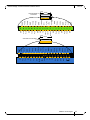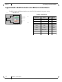
1
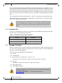
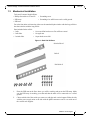
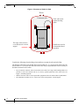
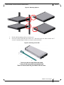
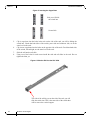
SwitchX-2 60 Port Ethernet Hardware System Installation Guide P/N: MSX1024B-1BFS, MSX1024B-1BRS, MSX1024B-2BFS, MSX1024B-2BRS www.mellanox.com Rev 1.0 NOTE: THIS HARDWARE, SOFTWARE OR TEST SUITE PRODUCT (“PRODUCT(S)”) AND ITS RELATED DOCUMENTATION ARE PROVIDED BY MELLANOX TECHNOLOGIES “AS-IS” WITH ALL FAULTS OF ANY KIND AND SOLELY FOR THE PURPOSE OF AIDING THE CUSTOMER IN TESTING APPLICATIONS THAT USE THE PRODUCTS IN DESIGNATED SOLUTIONS. THE CUSTOMER'S MANUFACTURING TEST ENVIRONMENT HAS NOT MET THE STANDARDS SET BY MELLANOX TECHNOLOGIES TO FULLY QUALIFY THE PRODUCTO(S) AND/OR THE SYSTEM USING IT. THEREFORE, MELLANOX TECHNOLOGIES CANNOT AND DOES NOT GUARANTEE OR WARRANT THAT THE PRODUCTS WILL OPERATE WITH THE HIGHEST QUALITY. ANY EXPRESS OR IMPLIED WARRANTIES, INCLUDING, BUT NOT LIMITED TO, THE IMPLIED WARRANTIES OF MERCHANTABILITY, FITNESS FOR A PARTICULAR PURPOSE AND NONINFRINGEMENT ARE DISCLAIMED. IN NO EVENT SHALL MELLANOX BE LIABLE TO CUSTOMER OR ANY THIRD PARTIES FOR ANY DIRECT, INDIRECT, SPECIAL, EXEMPLARY, OR CONSEQUENTIAL DAMAGES OF ANY KIND (INCLUDING, BUT NOT LIMITED TO, PAYMENT FOR PROCUREMENT OF SUBSTITUTE GOODS OR SERVICES; LOSS OF USE, DATA, OR PROFITS; OR BUSINESS INTERRUPTION) HOWEVER CAUSED AND ON ANY THEORY OF LIABILITY, WHETHER IN CONTRACT, STRICT LIABILITY, OR TORT (INCLUDING NEGLIGENCE OR OTHERWISE) ARISING IN ANY WAY FROM THE USE OF THE PRODUCT(S) AND RELATED DOCUMENTATION EVEN IF ADVISED OF THE POSSIBILITY OF SUCH DAMAGE. Mellanox Technologies 350 Oakmead Parkway Suite 100 Sunnyvale, CA 94085 U.S.A. www.mellanox.com Tel: (408) 970-3400 Fax: (408) 970-3403 Mellanox Technologies, Ltd. Beit Mellanox PO Box 586 Yokneam 20692 Israel www.mellanox.com Tel: +972 (0)74 723 7200 Fax: +972 (0)4 959 3245 © Copyright 2013. Mellanox Technologies. All Rights Reserved. Mellanox®, Mellanox logo, BridgeX®, ConnectX®, CORE-Direct®, InfiniBridge®, InfiniHost®, InfiniScale®, PhyX®, SwitchX®, UFM®, Virtual Protocol Interconnect® and Voltaire® are registered trademarks of Mellanox Technologies, Ltd. Connect-IB™, FabricIT™, MLNX-OS™, MetroX™, MetroDX™, ScalableHPC™, Unbreakable-Link™ are trademarks of Mellanox Technologies, Ltd. All other trademarks are property of their respective owners. Mellanox Technologies Document Number: 4180 Rev 1.0 SwitchX 40GigE 1U Ethernet Switch Installation Guide Table of Contents Table of Contents . . . . . . . . . . . . . . . . . . . . . . . . . . . . . . . . . . . . . . . . . . . . . . . . . . . . . . . . . . . . . . . . . 3 List of Figures . . . . . . . . . . . . . . . . . . . . . . . . . . . . . . . . . . . . . . . . . . . . . . . . . . . . . . . . . . . . . . . . . . . . 3 Revision History . . . . . . . . . . . . . . . . . . . . . . . . . . . . . . . . . . . . . . . . . . . . . . . . . . . . . . . . . . . . . . . . . . 3 About this Manual . . . . . . . . . . . . . . . . . . . . . . . . . . . . . . . . . . . . . . . . . . . . . . . . . . . . . . . . . . . . . . . . 4 Intended Audience . . . . . . . . . . . . . . . . . . . . . . . . . . . . . . . . . . . . . . . . . . . . . . . . . . . . . . . . . . . . . . . . . Related Documentation . . . . . . . . . . . . . . . . . . . . . . . . . . . . . . . . . . . . . . . . . . . . . . . . . . . . . . . . . . . . . . Document Conventions . . . . . . . . . . . . . . . . . . . . . . . . . . . . . . . . . . . . . . . . . . . . . . . . . . . . . . . . . . . . . . Mellanox Part Numbering Legend . . . . . . . . . . . . . . . . . . . . . . . . . . . . . . . . . . . . . . . . . . . . . . . . . . . . . Chapter 1 Mechanical Installation . . . . . . . . . . . . . . . . . . . . . . . . . . . . . . . . . . . . . . . . . . . . . . . . . 3 1.1 1.2 1.3 1.4 1.5 1.6 Chapter 2 Installation Safety Warnings . . . . . . . . . . . . . . . . . . . . . . . . . . . . . . . . . . . . . . . . . . . . . . . . . . . . . . . . . . 3 1.1.1 Installation Kits. . . . . . . . . . . . . . . . . . . . . . . . . . . . . . . . . . . . . . . . . . . . . . . . . . . . . . . . . . . . 6 Package Contents. . . . . . . . . . . . . . . . . . . . . . . . . . . . . . . . . . . . . . . . . . . . . . . . . . . . . . . . . . . . . . . . . . . 6 Mechanical Installation . . . . . . . . . . . . . . . . . . . . . . . . . . . . . . . . . . . . . . . . . . . . . . . . . . . . . . . . . . . . . . 7 Grounding the Switch . . . . . . . . . . . . . . . . . . . . . . . . . . . . . . . . . . . . . . . . . . . . . . . . . . . . . . . . . . . . . . 11 Power Connections and Initial Power On . . . . . . . . . . . . . . . . . . . . . . . . . . . . . . . . . . . . . . . . . . . . . . . 11 Battery Replacement . . . . . . . . . . . . . . . . . . . . . . . . . . . . . . . . . . . . . . . . . . . . . . . . . . . . . . . . . . . . . . . 12 Configuring the Switch . . . . . . . . . . . . . . . . . . . . . . . . . . . . . . . . . . . . . . . . . . . . . . . . 14 2.1 2.2 Chapter 3 4 4 4 6 Configuring the Switch for the First Time . . . . . . . . . . . . . . . . . . . . . . . . . . . . . . . . . . . . . . . . . . . . . . 14 Rerunning the Wizard . . . . . . . . . . . . . . . . . . . . . . . . . . . . . . . . . . . . . . . . . . . . . . . . . . . . . . . . . . . . . . 19 Connecting to the Switch Platform. . . . . . . . . . . . . . . . . . . . . . . . . . . . . . . . . . . . . . . 20 3.1 3.2 Starting an SSH Connection to the Switch (CLI) . . . . . . . . . . . . . . . . . . . . . . . . . . . . . . . . . . . . . . . . . 20 Resetting the Switch . . . . . . . . . . . . . . . . . . . . . . . . . . . . . . . . . . . . . . . . . . . . . . . . . . . . . . . . . . . . . . . 20 Appendix A QSFP Interface . . . . . . . . . . . . . . . . . . . . . . . . . . . . . . . . . . . . . . . . . . . . . . . . . . . . . . . 22 Appendix B RJ45 Console and Ethernet Interfaces. . . . . . . . . . . . . . . . . . . . . . . . . . . . . . . . . . . . 24 Appendix C Replacement Parts Ordering Numbers . . . . . . . . . . . . . . . . . . . . . . . . . . . . . . . . . . . 25 Mellanox Technologies 3 Rev 1.0 List of Figures Figure 1: Rack Rail Kit Parts . . . . . . . . . . . . . . . . . . . . . . . . . . . . . . . . . . . . . . . . . . . . . . . . . . . . . . . 7 Figure 2: Placement of Switch in Rack . . . . . . . . . . . . . . . . . . . . . . . . . . . . . . . . . . . . . . . . . . . . . . . 8 Figure 3: Mounting Options . . . . . . . . . . . . . . . . . . . . . . . . . . . . . . . . . . . . . . . . . . . . . . . . . . . . . . . 9 Figure 4: Screwing on the Rail . . . . . . . . . . . . . . . . . . . . . . . . . . . . . . . . . . . . . . . . . . . . . . . . . . . . . . 9 Figure 5: Inserting the Caged Nuts . . . . . . . . . . . . . . . . . . . . . . . . . . . . . . . . . . . . . . . . . . . . . . . . . 10 Figure 6: Slide the Rail into the Rail Slide . . . . . . . . . . . . . . . . . . . . . . . . . . . . . . . . . . . . . . . . . . . 10 Figure 7: Two Power Inlets - Electric Caution Notifications . . . . . . . . . . . . . . . . . . . . . . . . . . . . . 12 Figure 8: Console Port . . . . . . . . . . . . . . . . . . . . . . . . . . . . . . . . . . . . . . . . . . . . . . . . . . . . . . . . . . . 14 Figure 9: Reset Button . . . . . . . . . . . . . . . . . . . . . . . . . . . . . . . . . . . . . . . . . . . . . . . . . . . . . . . . . . . 21 3 Mellanox Technologies Rev 1.0 SwitchX 40GigE 1U Ethernet Switch Installation Guide Revision History Table 1 - Revision History of this Installation Guide Revision 1.0 Date February 2013 Details Initial release Mellanox Technologies 3 Rev 1.0 About this Manual This manual describes the installation and set-up instructions of the Mellanox switch family. Intended Audience This manual is intended for users and system administrators responsible for installing and setting up the switch platform. Related Documentation The documentation set accompanying the top of rack switch platform includes the following: Table 2 - Reference Documents Document Name Description Switch Hardware User Manual This document contains HW descriptions, LED assignments and HW specifications among other things. Switch Product Release Notes For possible hardware issues see the switch support product page. This requires a customer support login. Look up the relevant SwitchX®-based switch system/series release note file. Mellanox MLNX-OS Software User Manual This document contains information regarding configuring and managing Mellanox Technologies Switch Platforms. MLNX-OS™ Software Command Reference Guide Command Reference Guide for MLNX-OS™ listing all of the commands available through MLNX-OS™ with explanations and examples. All of these documents can be found on the Mellanox Website. They are available either through the product pages or through the support page with a login of user and password. Document Conventions When discussing memory sizes, MB and MBytes are used in this document to mean size in mega bytes. The use of Mb or Mbits (small b) indicates size in mega bits. This symbol makes recommendations to the user. 4 Mellanox Technologies Rev 1.0 SwitchX 40GigE 1U Ethernet Switch Installation Guide This symbol indicates information that is helpful to the user. This symbol indicates a situation that can potentially cause damage to hardware or software. BEWARE! This symbol indicates a situation that can potentially cause personal injury or damage to hardware or software. Mellanox Technologies 5 Rev 1.0 Mellanox Part Numbering Legend Place Field M Decoder Mellanox Technologies SX System Type SwitchX® switch Family P Data Transfer Protocol 1 = Ethernet R Size of box 0 = 1U 1 = 1.5U 2 = 2U FF 40 Gb/s equivalent throughput 16 = 640Gb/s 24 = 960Gb/s 35 = 2880 Gb/s Light version of the Management software 36 = 2880 Gb/s C Data Rate X = 10Gb/s Ethernet B = 40Gb/s Ethernet - Separator P # Power Supplies 0=0, 1=1, 2=2.... M Depth of the Unit S = standard depth, B = short depth Y Air Flow direction R= Connector side to Power side airflow F= Power Side side to Connector side airflow R Chip Generation R – SwitchX S – SwitchX-2 6 Mellanox Technologies Rev 1.0 SwitchX 40GigE 1U Ethernet Switch Installation Guide 1 Mechanical Installation Installation and initialization of the switch platform are straightforward processes, requiring attention to the normal mechanical, power, and thermal precautions for rack-mounted equipment. 1.1 Installation Safety Warnings For Safety Warnings in French, German, and Spanish see the User Manual (you can download it from the mellanox.com website MSX1024 product page). 1. Installation Instructions Read all installation instructions before connecting the equipment to the power source. 2. Over-temperature This equipment should not be operated in an area with an ambient temperature exceeding the maximum recommended: 45°C (113°F). Moreover, to guarantee proper air flow, allow at least 8cm (3 inches) of clearance around the ventilation openings. 3. Stacking the Chassis The chassis should not be stacked on any other equipment. If the chassis falls, it can cause bodily injury and equipment damage. 4. Redundant Power Supply Connection - Electrical Hazard This product includes a blank cover over the space for the redundant power supply. Do not operate the product if the blank cover is not securely fastened or if it is removed. 5. During Lightning - Electrical Hazard During periods of lightning activity, do not work on the equipment or connect or disconnect cables. 6. Copper Cable Connecting/Disconnecting Copper cables are heavy and not flexible, as such they should be carefully attached to or detached from the connectors. Refer to the cable manufacturer for special warnings and instructions. Mellanox Technologies 3 Rev 1.0 Mechanical Installation 7. Rack Mounting and Servicing When this product is mounted or serviced in a rack, special precautions must be taken to ensure that the system remains stable. In general you should fill the rack with equipment starting from the bottom to the top. 8. Equipment Installation This equipment should be installed, replaced, or serviced only by trained and qualified personnel. 9. Equipment Disposal Disposal of this equipment should be in accordance to all national laws and regulations. 10. Local and National Electrical Codes This equipment should be installed in compliance with local and national electrical codes. 11. Hazardous Radiation Exposure Caution – Use of controls or adjustment or performance of procedures other than those specified herein may result in hazardous radiation exposure. CLASS 1 LASER PRODUCT and reference to the most recent laser standards: IEC 60 825-1:1993 + A1:1997 + A2:2001 and EN 60825-1:1994+A1:1996+ A2:2001 12. UL Approved AC Power Cords For North American power connection, select a power supply cord that is UL Listed and CSA Certified 3 - conductor, [18 AWG], terminated in a molded on plug cap rated at 125 V, [15 A], with a minimum length of 1.5m [six feet] but no longer than 4.5m For European connection, select a power supply cord that is internationally harmonized and marked “<HAR>”, 3 - conductor, minimum 0,75 mm2 wire, rated at 300 V, with a PVC insulated jacket. The cord must have a molded on plug cap rated 250 V, 10 A. 4 Mellanox Technologies Rev 1.0 SwitchX 40GigE 1U Ethernet Switch Installation Guide 13. Do Not Use the Switch as a Shelf or Work Space Caution: Slide/rail mounted equipment is not to be used as a shelf or a work space. 14. WEEE Directive According to the WEEE Directive 2002/96/EC, all waste electrical and electronic equipment (EEE) should be collected separately and not disposed of with regular household waste. Dispose of this product and all of its parts in a responsible and environmentally friendly way. Mellanox Technologies 5 Rev 1.0 Mechanical Installation The switch platform can be rack mounted and is designed for installation in a standard 19” rack. The power side of the switch includes a hot-swap power supply module, a blank cover for an optional second PS unit for redundancy, and 2 hot-swap fan trays. There are two possible air flow directions. Be sure that the switch air flow direction is compatible with your system, rack, and PS units. The connector side of the switch has the ports, system LEDs, and management connection ports. The switch platform contains auto-sensing 100 - 240 VAC connections for all possible PS units. The installer should use a rack capable of supporting the mechanical and environmental characteristics of a fully populated platform. The rack mounting holes conform to the EIA-310 standard for 19-inch racks. Take precautions to guarantee proper ventilation in order to maintain good airflow at ambient temperature. Cable routing in particular should not impede the air exhaust from the chassis. 1.1.1 Installation Kits There are two Installation kit options. One long and one short. Both the standard and the short switches can be mounted using the long rail kit. Table 3 - Installation Kit According to Rack Size 1.2 Kit OPN Rack Size MSX60-BKIT 40-60 cm deep MSX60-SKIT 60-80 cm deep Package Contents Before you install your new switch, unpack the system and check to make sure that all the parts have been sent, check this against the parts list below. Check the parts for visible damage that may have occurred during shipping. The switch comes packed with the following items: •1 X – switch •1 X – installation kit • X – power cable one for each PS unit – Type C13-C14 • A single power cord for each power supply unit can be ordered at no extra charge •1 X – Harness • HAR000028 – Harness RS232 2M cable – DB9 to RJ-45switches •1 X – Quick Start Guide •1 X – China RoHS statement If anything is damaged or missing, contact your customer representative immediately. For customer support go to: www.mellanox.com =>Support => Customer Support Portal Login 6 Mellanox Technologies Rev 1.0 SwitchX 40GigE 1U Ethernet Switch Installation Guide 1.3 Mechanical Installation Tools and Customer Supplied Parts: • Phillips Screwdrivers #1 and #2 • ESD strap • ESD mat • Grounding screw • Grounding wire sufficient to reach a valid ground. For racks from 60cm to 80cm deep either use the standard depth switches with the long rail kit or the short switches with the long rail kit. Parts included in the rail kit: • 2 rails • 2 rail slides • 2 switch slides • 16 recessed flat head screws You will have extras! • 10 caged nuts • 10 pan head screws M6 Figure 1: Rack Rail Kit Parts Switch slide x2 Rail x2 Rail slide x2 1. 2. Place the ESD mat on the floor where you will be working and put on the ESD strap. Make sure the ESD strap is touching your skin and that the other end is connected to a verified ground. Choose which side of the switch you want even with the rack vertical support. Either the side with the power supply units or the side with the QSFP connectors can be even with one of the vertical rack supports. Mellanox Technologies 7 Rev 1.0 Mechanical Installation Figure 2: Placement of Switch in Rack Doors Connector side Cable with recommended bending radius 19" (482.6mm) Switch This edge of the switch is even with the rack vertical support Insufficient room for recommended bending radius Power / Spine side Doors Consider the following when deciding where and how to mount the rails and rail slides: The distance between the rack and the door can be as little as 1.57” (4 cm) on one side of the rack and as much as 7”(18 cm) on the other side of the rack. Keep in mind that there can be as many as 60cables connected to the switch. 8 • Do you want the connector side recessed in the rack to allow for a larger cable bending radius? It is possible to recess the connector side by 2” (5cm) by optional placement of the switch rails. See Figure 3,“Mounting Options”. • Will the connector side be recessed past other equipment in the rack and will this be problematic? • The installation kit allows for a 2” (5cm) recess of the switch past the vertical support. Mellanox Technologies Rev 1.0 SwitchX 40GigE 1U Ethernet Switch Installation Guide Figure 3: Mounting Options 3. 4. Decide which mounting option you want to use. Screw the switch slides onto the switch. Use 5 flat head screws for short switches and 7 screws for standard depth switches, to connect each switch slide. Figure 4: Screwing on the Rail 5 screws per side are needed for the short switch. 7 screws per side are needed for the standard switch. There are 16 screws in the kit; you will have left over screws. Mellanox Technologies 9 Rev 1.0 Mechanical Installation Figure 5: Inserting the Caged Nuts Side you will slide the switch into Second side 5. 6. 7. 8. Clip 6 caged nuts into the holes in the rack on the side of the rack you will be sliding the switch into. Check that both sides of the switch, power side and connector side, are at the same level in the rack. Clip 4 more caged nuts into the holes on the opposite side of the rack. Check that both sides of the switch, left and right, are the same level in the rack. Slide the rail into the rail slide. Using two of the bolts for each corner install the rails and rail slides in the rack. Do not tighten the bolts yet. Figure 6: Slide the Rail into the Rail Slide This side of the rail kit goes on the side of the rack you will slide the switch into. This is the same side of the switch that will be next to the vertical support. 10 Mellanox Technologies Rev 1.0 SwitchX 40GigE 1U Ethernet Switch Installation Guide 9. 10. 11. 12. 13. 14. Slide the switch into the rails. Tighten the bolts to 9.2 Nm or 81.5 pound inches. Put the switch into place and screw the bolts into the nuts. Tighten the bolts to 9.2 Nm or 81.5 pound inches. Ground the switch. Plug in the power cables. Check the Status LEDs and confirm that all of the LEDs show status lights consistent with normal operation. Status LEDs 5 Minutes After Power On PS UID RST Warning: Any yellow or red status LEDs are cause for concern and must be dealt with immediately. It can take up to 5 minutes to boot up, during which time the status LED may indicate red. 15. 1.4 You can start connecting all of the cables to the switch. Grounding the Switch Check to determine if your local or national electrical codes require an external ground to all IT components. If so, connect a ground wire to one of the casing screws and connect the other end to a valid ground. If you choose to not use the ground screw, make sure that the rack is properly grounded and that there is a valid ground connection between the chassis of the switch and the rack. Test the ground using an Ohm meter. Some national and/or local codes may require IT components to be bonded and externally grounded (not including the power cord ground). You must follow all national and local codes when installing this equipment. 1.5 Power Connections and Initial Power On The switch platform ships witone or twoh power supply units. For switches with only one unit installed, a second PS unit may be installed at a later time. Each supply has a separate AC recep- Mellanox Technologies 11 Rev 1.0 Mechanical Installation tacle. The input voltage is auto-adjusting for 100 - 240VAC, 50-60Hz power connections. The power cords should be standard 3-wire AC power cords including a safety ground and rated for 15A or higher. Caution: The switch platform will automatically power on when AC power is applied. There is no power switch. Check all boards, power supplies, and fan tray modules for proper insertion before plugging in a power cable. Caution: After inserting a power cable and confirming the green system status LED light is on; make sure that the Fan Status indicator shows green. If the fan status indicator is not green then unplug the power connection and check that the fan module is inserted properly and that the mating connector of the fan unit is free of any dirt and/or obstacles. Caution: When turning off the switch, make sure ALL Connector LEDS are off to ensure a powered down status. Do not hot swap the power supply if your switch has only one power supply. You must power down the system to replace the power supply unit when there is only one PS unit in the switch. Figure 7: Two Power Inlets - Electric Caution Notifications CAUTION ACHTUNG Risk of electric shock and energy hazard. The two PS units are independent. Gafahr des elektrischen Schocks. Entferrnen des Netzsteckers elnes Netzteils spannungsfrei. Um alle Einhieten spannungsfrei zu machen sind die Netzstecker aller Netzteile zu entfernen Disconnect all power supplies to ensure a powered down state inside of the switch platform. 1.6 ATTENTION Risque de choc et de danger e’lectriques. Le de’branchment d’une seule alimentation stabilise’e ne de’branch uniquement qu’un module “Alimentation Stabilise’e”. Pour isoler completement le module en cause, Il faut de’brancher toutes les alimentations stabilise’es. Battery Replacement Mellanox Technologies does not support battery replacement. Customer removal of the switch cover will void the warrantee. Only Remove the cover to comply with WEEE directives or to disassemble for environmentally approved disposal. 12 Mellanox Technologies Rev 1.0 SwitchX 40GigE 1U Ethernet Switch Installation Guide Customer removal of the switch cover will void the warrantee. Mellanox Technologies 13 Rev 1.0 2 Configuring the Switch Configuring the Switch The procedures described in this chapter assume that you have already installed and powered-on your switch according to the instructions in the Switch Installation Guide, this document. 2.1 Configuring the Switch for the First Time Connect the host PC to the Console (RJ-45) port of the switch system using the supplied cable. The Console ports for systems are shown below as examples. Step 1. Figure 8: Console Port SX1024 6 57 58 59 60 Connect the host PC to here Mellanox Make sure to connect to the Console RJ-45 port of the switch and not to the (Ethernet) MGT port. No remote IP connection is available at this stage. Configure a serial terminal program (for example, HyperTerminal, minicom, or Tera Term) on your host PC with the settings described in Table 4. Step 2. Table 4 - Serial Terminal Program Configuration Parameter 14 Setting Baud Rate 9600 Data bits 8 Stop bits 1 Parity None Mellanox Technologies Rev 1.0 SwitchX 40GigE 1U Ethernet Switch Installation Guide Table 4 - Serial Terminal Program Configuration (Continued) Parameter Flow Control Setting None Step 3. Login (from a serial terminal program) as admin and use admin as password. This starts the Mellanox configuration wizard. Step 4. Go through the Mellanox configuration wizard. Table 5 shows an example of a wizard session. Table 5 - Configuration Wizard Session - IP Configuration by DHCP (Sheet 1 of 2) Wizard Session Display (Example) Comments Mellanox configuration wizard Do you want to use the wizard for initial configuration? yes You must perform this configuration the first time you operate the switch or after resetting the switch. Type ‘y’ and then press <Enter>. Step1: Hostname? [switch-1] If you wish to accept the default hostname, then press <Enter>. Otherwise, type a different hostname and press <Enter>. Step 2: Use DHCP on mgmt0 interface? [no] Perform this step to obtain an IP address for the switch. (eth0 is the management port of the switch.) If you wish the DHCP server to assign the IP address, type ‘yes’ and press <Enter>. If you type ‘no’ (no DHCP), then you will be asked whether you wish to use the ‘zeroconf’ configuration or not. If you enter ‘yes’ (yes Zeroconf), the session will continue as shown in Table 6. If you enter ‘no’ (no Zeroconf), then you need to enter a static IP, and the session will continue as shown in Table 7. Step 3: Enable IPv6? [yes] yes The management interface will be able to use IPv6 addresses. Step 4: Enable IPv6 autoconfig (SLAAC) on mgmt0 interface? [no] no This turns on autoconfiguration of the IPv6 addresses. This is unsuitable for DHCPv6. Mellanox Technologies 15 Rev 1.0 Configuring the Switch Table 5 - Configuration Wizard Session - IP Configuration by DHCP (Sheet 2 of 2) Wizard Session Display (Example) Step 5: Admin password (Press <Enter> to leave unchanged)? <new_password> Step 6: Confirm admin password? <new_password> Comments To avoid illegal access to the machine, please type a password and then press <Enter>. Then confirm the password by re-entering it. Note that password characters are not printed. You have entered the following information: 1. Hostname: <switch name> 2. Use DHCP on mgmt0 interface: yes 3. Enable IPv6: yes 4. Enable IPv6 autoconfig (SLAAC) on mgmt0 interface: no 5. Admin password (Enter to leave unchanged): (CHANGED) To change an answer, enter the step number to return to. Otherwise hit <enter> to save changes and exit. Choice: <Enter> Configuration changes saved. To return to the wizard from the CLI, enter the “configuration jump-start” command from configuration mode. Launching CLI... <switch name> [> 16 Mellanox Technologies The wizard displays a summary of your choices and then asks you to confirm the choices or to re-edit them. Either press <Enter> to save changes and exit, or enter the configuration step number that you wish to return to. Note: To run the command “configuration jump-start” you must be in Config mode. Rev 1.0 SwitchX 40GigE 1U Ethernet Switch Installation Guide Table 6 - Configuration Wizard Session - IP Zeroconf Configuration Wizard Session Display - IP Zeroconf Configuration (Example) Mellanox configuration wizard Do you want to use the wizard for initial configuration? y Step 1: Hostname? [switch-112126] Step 2: Use DHCP on mgmt0 interface? [yes] no Step 3: Use zeroconf on mgmt0 interface? [no] yes Step 4: Default gateway? [For example:192.168.10.1] Step 5: Primary DNS server? Step 6: Domain name? Step 7: Enable IPv6? [yes] yes Step 8: Enable IPv6 autoconfig (SLAAC) on mgmt0 interface? [no] no Step 9: Admin password (Enter to leave unchanged)? Step 9: Confirm admin password? (Enter to leave unchanged)? You have entered the following information: 1. Hostname: switch-112126 2. Use DHCP on mgmt0 interface: no 3. Use zeroconf on mgmt0 interface? [no] yes 4. Default gateway: 192.168.10.1 5. Primary DNS server: 6. Domain name: 7. Enable IPv6: yes 8. Enable IPv6 autoconfig (SLAAC) on mgmt0 interface: no 9. Admin password (Enter to leave unchanged): (unchanged) To change an answer, enter the step number to return to. Otherwise hit <enter> to save changes and exit. Choice: Configuration changes saved. To return to the wizard from the CLI, enter the "configuration jump-start" command from configure mode. Launching CLI... switch-1 > Mellanox Technologies 17 Rev 1.0 Configuring the Switch Table 7 - Configuration Wizard Session - Static IP Configuration Wizard Session Display - Static IP Configuration (Example) Mellanox configuration wizard Do you want to use the wizard for initial configuration? y Step 1: Hostname? [switch-112126] Step 2: Use DHCP on mgmt0 interface? [yes] n Step 3: Use zeroconf on mgmt0 interface? [no] Step 4: Primary IP address? [for example 192.168.10.4] Mask length may not be zero if address is not zero (interface eth0) Step 5: Netmask? [0.0.0.0] 255.255.255.0 Step 6: Default gateway? [for example 192.168.10.1] Step 7: Primary DNS server? Step 8: Domain name? Step 9: Enable IPv6? [yes] yes Step 10: Enable IPv6 autoconfig (SLAAC) on mgmt0 interface? [no] no Step 11: Admin password (Enter to leave unchanged)? You have entered the following information: 1. Hostname: switch-112126 2. Use DHCP on mgmt0 interface: no 3. Use zeroconf on mgmt0 interface: no 4. Primary IP address: 192.168.10.4 5. Netmask: 255.255.255.0 6. Default gateway: 192.168.10.1 7. Primary DNS server: 8. Domain name: 9. Enable IPv6: yes 10.Enable IPv6 autoconfig (SLAAC) on mgmt0 interface: no 11.Admin password (Enter to leave unchanged): (unchanged) To change an answer, enter the step number to return to. Otherwise hit <enter> to save changes and exit. Choice: Configuration changes saved. To return to the wizard from the CLI, enter the "configuration jump-start" command from configure mode. Launching CLI... switch-1 > Step 5. Before attempting a remote (for example, SSH) connection to the switch, check the mgmt0 interface configuration. Specifically, verify the existence of an IP address. To check the current mgmt0 configuration, enter the following commands: sx-43 [standalone: master] > enable sx-43 [standalone: master] # show interfaces mgmt0 18 Mellanox Technologies Rev 1.0 SwitchX 40GigE 1U Ethernet Switch Installation Guide The following is an example of the output: Interface mgmt0 state Admin up: yes Link up: yes IP address: 192.168.10.43 Netmask: 255.255.255.0 Speed: 1000Mb/s (auto) Duplex: full (auto) Interface type: ethernet Interface source: physical MTU: 1500 HW address: 00:02:C9:11:2A:AE Comment: RX bytes: 1343502058 TX bytes: 313920869 RX packets: 17589211 TX packets: 992717 RX mcast packets: 0 TX discards: 0 RX discards: 0 TX errors: 0 RX errors: 0 TX overruns: 0 RX overruns: 0 TX carrier: 0 RX frame: 0 TX collisions: 0 TX queue len: 2.2 1000 Rerunning the Wizard If you want to rerun the wizard run the following commands: sx-43 [standalone: master] > enable sx-43 [standalone: master]# configure terminal sx-43 [standalone: master]# configuration jump-start Mellanox Technologies 19 Rev 1.0 Connecting to the Switch Platform 3 Connecting to the Switch Platform 3.1 Starting an SSH Connection to the Switch (CLI) Step 1. Set up an Ethernet connection between the switch and a local network machine (“the remote machine” henceforth) using a standard RJ-45 connector. Step 2. Connect to the remote machine (rem_mach1 is used as an example). Step 3. Start a remote shell to the switch using the following command using <switch_IP_address> is the IP address of the switch. rem_mach1 > ssh -l <username> <switch ip address> Mellanox MLNX-OS Switch Management Password: Last login: Thu Apr 28 11:24:13 2011 from 192.168.10.1 Mellanox Switch sx-43 [standalone: master] > Step 4. 3.2 You can enter any supported command now. Resetting the Switch On the connector side panel under the system LEDs is a reset button. This reset button requires a tool to be pressed. DO NOT use a sharp pointed object such as needle or push pin for pressing the Reset button. Sharp objects can cause damage, use a flat object to press this reset button. 20 Mellanox Technologies Rev 1.0 SwitchX 40GigE 1U Ethernet Switch Installation Guide Figure 9: Reset Button Press the reset button to reset the main and management CPUs and to delete the existing password. ! 1 2 PS1 PS2 ! UID RST This button resets both the CPU of the switch device and the CPU of the management module. It thereby resets all of the ports by bringing them down and powering them up when the button is pushed. A quick push of this button performs this reset. When the button is held down for 15 seconds the switch is reset and the password is deleted. You will then be able to enter without a password and make a new password for the user admin. The SwitchX Series User Manuals can be found at: http://www.mellanox.com Mellanox Technologies 21 Rev 1.0 Connecting to the Switch Platform Appendix A: QSFP Interface 20 21 22 23 24 25 26 27 28 29 30 Rx2n 18 Rx2p Rx1p 17 GND GND 16 Rx4n Rx3n Rx4p Rx3p GND GND ModPrsL SDA IntL SCL VccTx Vcc Rx Vcc1 ResetL LPMode 32 GND GND ModSelL 15 14 Ground Tx2n Transmitter Inverted Data Input 3 Tx2p Transmitter Non-Inverted Data Input 10 4 GND Ground 9 5 Tx4n Transmitter Inverted Data Input 8 6 Tx4p Transmitter Non-Inverted Data Input 7 7 GND 6 8 ModSelL Module Select 5 4 9 ResetL Module Reset 10 Vcc Rx +3.3 V Power supply receiver 12 11 Tx3n 35 GND Tx4n GND 36 Tx1p Tx2p 3 Tx1n GND Tx2n 2 1 Mellanox Technologies Signal Description GND Tx4p GND Connector Connector Pin Pin Name Number 2 Tx3p 38 Table 8 - QSFP Connector Pinout 1 13 34 37 22 GND Rx1n 31 33 19 GND Ground 11 SCL 2-wire serial interface clock 12 SDA 2-wire serial interface data 13 GND Ground 14 Rx3p Receiver Non-Inverted Data Output 15 Rx3n Receiver Inverted Data Output 16 GND Ground 17 Rx1p Receiver Non-Inverted Data Output 18 Rx1n Receiver Inverted Data Output 19 GND Ground 20 GND Ground 21 Rx2n Receiver Inverted Data Output 3 22 Rx2p Receiver Non-Inverted Data Output 3 23 GND Ground 24 Rx4n Receiver Inverted Data Output 3 25 Rx4p Receiver Non-Inverted Data Output 3 26 GND Ground 27 ModPrsL 28 IntL 29 Vcc Tx +3.3 V Power supply transmitter 30 Vcc 1 +3.3 V Power Supply 31 LPMode 32 GND Module Present Interrupt Low Power Mode Ground 33 Tx3p Transmitter Non-Inverted Data Input 34 Tx3n Transmitter Inverted Data Input 35 GND Ground 36 Tx1p Transmitter Non-Inverted Data Input 37 Tx1n Transmitter Inverted Data Input 38 GND Ground SDA GND RX3p RX3n GND SCL RX1n ResetL RX1p 15 GND 14 VccRx 13 19 12 ModSelL 20 GND 21 RX2n 22 RX2p 23 GND 24 RX4n 25 RX4p 26 GND 27 ModPrsL 28 IntL 29 VccTx 30 Vcc1 31 LPMode 13 12 11 1 0 9 8 7 6 5 4 3 2 1 GND 11 1 0 9 18 8 17 7 16 6 GND 14 TX2n 32 GND 15 TX2p 33 TX3p GND 5 TX4p 16 TX4n 34 TX3n TX4p 4 TX4n GND 19 18 17 ModSelL 35 GND ResetL 3 GND SCL 36 TX1p SDA 2 TX2p GND 37 TX1n RX3p 1 TX2n GND 3 8 TX1n 3 7 TX1p 3 6 GND 3 5 TX3n 3 4 TX3p 3 3 GND 3 2 LPMode 3 1 Vcc1 30 RX3n VccRx GND RX1n RX1p GND 38 GND Top 18.35 Top 18.35 View into Rear of Connector VccTx 29 IntL 28 ModPrsL 27 GND 26 RX4p 25 RX4n 24 GND 23 RX2p 22 RX2n 21 GND 20 GND Rev 1.0 SwitchX 40GigE 1U Ethernet Switch Installation Guide 8.50 View into Front of Cage 8.50 23 Mellanox Technologies Rev 1.0 Connecting to the Switch Platform Appendix B: RJ45 Console and Ethernet Interfaces The RJ45 Console and Ethernet interfaces uses the EIA 568A standard wiring color coding. J34 CO NSO LE Table 9 - RJ45 Pinout TXD+ TXDRXD+ GND GND RXDGND GND R J45_R T S # R J45_D T R # R J45_T X D GND GND R J45_R X D GND GND P in 1 Connection Signal Pin# Color TXD+ RJ45_RTS# 1 G/W TXD- RJ45_DTR# 2 G RXD+ RJ45_TXD 3 O/W GND GND 4 Bl GND GND 5 Bl/W RXD- RJ45_RXD 6 O GND GND 7 Br/w GND GND 8 Br P in 8 L o o k in g in to th e S o c k e t 24 Mellanox Technologies Rev 1.0 SwitchX 40GigE 1U Ethernet Switch Installation Guide Appendix C: Replacement Parts Ordering Numbers Table 10 - Replacement Parts Ordering Numbers Part Description OPN I2C DB9 or RJ45 to USB Adapter MTUSB-1 Fan module with power supply side to connector side air flow MSX60-FF Fan module with connector side to power supply side air flow MSX60-FR 300W Power Supply w/ Power Supply Side to Connector side air flow MSX60-PF 300W Power Supply w/ Connector side to Power Supply side air flow MSX60-PR Power cord Type C13-C14 ACC000500 Installation Kit for short switches in racks 40-60 cm deep MSX60-BKIT Installation Kit for short or standard switches in racks 60-80 cm deep MSX60-SKIT Mellanox Technologies 25