1
IMPORTANT
MANUAL
DO NOT THROW
AWAY
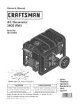
OWNER'S
MANUAL
MODEL NO.
536.886540
Caution:
Read and Follow
All Safety Rules
and Instructions
Before Operating
This Equipment
®
5 HORSEPOWER
22" DUAL STAGE
SNOW THROWER
120V. ELECTRIC START
® Assembly
O Operation
O Customer Responsibilities
• Service and Adjustments
® Repair Parts
SEARS,
ROEBUCK
AND CO., Hoffman
Estates,
IL 60179
U.S.A.
SAFETY
RULES
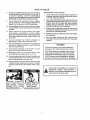
PLACE
WIRE
WHERE
IT CANNOT
CONTACT
SPARK
PLUG
CAUTION:
ALWAYS
DISCONNECT
SPARK
PLUG WIRE
AND
TO PREVENT
ACCIDENTAL
STARTING
WHEN
SETTING-UP,
TRANSPORTING,
ADJUSTING
OR MAKING REPAIRS.
&
&
IMPORTANT
SAFETY
STANDARDS
REQUIRE
OPERATOR
PRESENCE
CONTROLS
TO MINIMIZE
THE
RISK OF INJURY.. YOUR SNOW THROWER
IS EQUIPPED
WITH SUCH CONTROLS.
DO NOT
ATTEMPT
TO DEFEAT THE FUNCTION
OF THE OPERATOR
PRESENCE
CONTROL
UNDER
ANY CIRCUMSTANCES.
TRAINING
1,
6.
Read the operator's manual carefully° Be
thoroughly familiar with the controls and the
proper use of the snow thrower. Know how to
stop the snow thrower and disengage the
controls quickly.
2o Never allow children to operate the snow thrower
and keep them away while it is operating Never
allow adults to operate the snow thrower without
proper instruction, Do not carry passengers.
7,, Never attempt to make any adjustments whilethe
engine (motor) is running (except when
specifically recommended by the manufacturer)_
8.
Let engine (motor) and snow thrower adjust to
outdoor temperatures before starting to clear
snow.
9.
Always wear safety glasses or eye shields during
operation or while performing an adjustment or
repair to protect eyes from foreign objects that
may be thrown from the snow thrower.
3o Keep the area of operation clear of all persons,
particularly small children, and pets.
4_ Exercise caution to avoid slipping or falling,
especially when operating in reverse..
PREPARATION
1. Thoroughly inspect the area where the snow
thrower is to be used and remove all doormats,
sleds, boards, wires, and other foreign objects°
2.
Disengage all clutches and shift into neutral
before starting the engine (motor).
3.
Do not operate the snowthrower without wearing
adequate winter outer garments. Wear footwear
that will improve footing on slippery surfaces.
4.
Handle fuel with care; it is highly flammable,
OPERATION
1. Do not put hands or feet near' or under rotating
parts. Keep clear of the discharge opening at all
times_
2.
4_
(b) Never remove fuel tank cap or add fuel to a
running engine or hot engine.
(d) Replace fuel tank cap securely
spilled fuel.,
and wipe up
_e) Never store fuel or snow thrower with fuel in
the tank inside of a building where fumes may
reach an open flame or spark_
(f)
.
Check fuel supply before each use, allowing
space for expansion as the heat of the engine
(motor) and/or sun can cause fuel to expand.
Use extension cords and receptacles as specified
by the manufacturer
for all snow throwers with
electric drive motors or electric starting motors.
Exercise extreme caution when operating on or
crossing gravel drives, walks, or roads. Stay alert
for hidden hazards or traffic.
After striking a foreign object, stop the engine
(motor), remove the wire from the spark plug,
disconnect the cord on electric motors,
thoroughly inspect the snow thrower for any
damage, and repair the damage before restarting
and operating the snow thrower.
(a) Use an approved fuel container..
(c) Fill fuel tank outdoors with extreme care..
Never fill fuel tank indoor&
Adjust the snow thrower'height to clear gravel or
crushed rock surfaces.
If the snow thrower should start to vibrate
abnormally,
stop the (motor)
and check
immediately for the cause° Vibration is generally
a warning of trouble.
5._ Stop the engine (motor) whenever you leave the
operating position, before unclogging the auger/
impeller housing or discharge guide, and when
making any repairs, adjustments, or inspections.
6.
When cleaning, repairing, or inspecting, make
certain the auger/impeller and all moving parts
have stopped_ Disconnect the spark plug wire
and keep the wire away from the plug to prevent
accidental starting.
7.
Take all possible precautions when leaving the
snow thrower unattended. Disengage the auger/
impeller, shift to neutral, stop engine, and
remove key..
SAFETY
8,
9o
RULES
MAINTENANCEAND
DO not run the engine indoors, except when starting
the engine and for transporting the snow thrower in
or out of the building.
Open the outside doors;
exhaust fumes are dangerous (containing CARBON
MONOXIDE, an ODORLESS and DEADLY GAS)°
1t.
1..
Check shear bolts and other boils frequently
for
improper tightness to be sure the snow thrower
is in sate working condition_
2o
Never store the snow thrower with tuel in the fuel
tank inside a building where ignition sources are
present such as hot water and space heaters,
clothes dryers, and the like.. Allow the engine to
coot before storing in any enclosure..
3
Always refer to operator's
manual instructions
for important details if the snow thrower is to be
stored tor an extended period,
Do not clear snow across the face of slopes.
Exercise caution
when changing
direction
on
slopes. Do not attempt to clear steep slopes_
10. Never operate the snow thrower without proper
guards, plates or other safety protective
devices
in place..
Never operate
the snow thrower
near glass
enclosures,
automobiles,
window
wells,
drop-offs,
and the like wit hour proper adjustment
of the snow discharge
angle Keep children and
pets away.
12o Do not overload
the machine
capacity
attempting
to clear snow at too fast a rate.
4o Maintain or replace safety
as necessary.
and instruction
5,.
a tew minutes
after
freeze-up of the auger/
by
13. Neveroperate
the snow thrower at high transport
speeds on slippery surlaces.
Look behind and
use care when backing.
14.. Never direct discharge
at bystanders
anyone in front of the snow thrower..
STORAGE
Run the snow thrower
throwing snow to prevent
impeller°
labels,
WARNING
This snow thrower is for use on sidewalks,
driveways,
and other ground level surfaces.
or allow
15. Disengage
power to the auger/impeller
when
snow thrower is transported
or not in use.
CAUTION should be exercised
while using on
steep sloping surfaces.
DO NOT USE SNOW
THROWER ON SURFACES ABOVE GROUND
16. Use only attachments
and accessories
approved
by the manufacturer
of the snow thrower (such
as tire chains, electric start kitS, etc )
LEVEL such as roofs of residences,
garages,
porches or other such structures
or bulldingso
'17. Never operate the snow thrower
without good
visibility
or light,. Always be sure ot your footing,
and keep a firm hold on the handles Walk; never
run..
LOOK FOR THIS SYMBOL
_
IMPORTANT
SAFETY
MEANS--ATTENTION!!!
YOUR SAFETY
CAUTION:
ING
AUGER,
_LOTH1NG
AWAY!
DISCHARGE
CHUTE!
3
TO POINT OUT---]
PRECAUTIONS_
BECOME ALERT!!! IT !_
IS INVOLVED_
/
PRODUCT
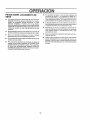
CONGRATULATIONS
on your purchase of a Sears
Craftsman Snow Thrower
It has been designed, engineered and manufactured to give you the best possible
dependability and performance
Should you experience any problem you cannot easily
remedy, please contact your nearest Sears Service
Center/Department
Sears has competent, wetHrained
technicians and the proper tools to service or repair this
unil
Please read and retain this manual The instruclions will
enable you Io assemble and maintain your snow thrower
]roperly, Always observe the "SAFETY RULES/
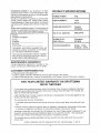
MODEL
NUMBER
HORSE
SPECIFICATIONS
POWER:
5 hp
DISPLACEMENT:
12.04
cu_ in.
GASOLINE
2 quarts
CAPACITY:
Unleaded
OIL (21 oz. Capacity):
SAE 5W-30
SPARK PL.UG :
Champion
RJ19LM
536 886540
SERIAL
NUMBER
DATE OF
PURCHASE
(GAP .030 in.)
VALVE CLEARANCE:
THE MODEL AND SERIAL NUMBERS WILL BE
FOUND ON A DECAL ATTACHED TO THE REAR
OF THE SNOW THROWER HOUSING
Intake: .010 In,
Exhaust:
.010 In.
YOU SHOULD RECORD BOTH SERIAL NUMBER
AND DATE OF PURCHASE AND KEEP IN A SAFE
PLACE FOR FUTURE REFERENCE
MAINTENANCE
AGREEMENT
A Sears Mainlenance
Agreement is available on this
product Contact your nearest Sears Slore for details
CUSTOMER
RESPONSIBILITIES
• Read and observe the safety rules
o Follow a regular schedule in maintaining, caring to_ and using your snow thrower
• Follow the instructions under "Customer Responsibilities
and "Storage
sections ot this owners
manual
TWO YEAR LIMITED WARRANTY ON CRAFTSMAN
SNOW THROWER
For lwo years from the date of purchase, when this Craftsman Snow Thrower is maintained, lubricated
and tuned-up according to the instructions in the owner s manual, Sears will repair, free of charge, any
detecl in material and workmanship
1I this Craftsman Snow Thrower is used Ior commercial
90 days from the date of purchase
This warranty
,, Expendable
pins
t
or renlat purposes,
this warranty
applies !or only
does not cover the following:
ilems which become worn during normal use, such as spark plugs, drive belts and shear
Repairs necessary because ol operator abuse or negligence, including benl crankshalts and lhe lailure
to maintain the equipment according to the instructions contained in the owner's manual
WARRANTY SERVICE IS AVAILABLE BY RETURNING THE CRAFTSMAN SNOW THROWER TO THE
NEAREST SEARS SERVICE CENTER/DEPARTMENT
IN THE UNITED STATES
THIS WARRANTY
APPLIES ONLY WHtLE THIS PRODUCT IS IN USE IN THE UNITED STATES
This warranly gives you specific legal rights, and you may also have other rights which may vary from
state !o slate,
SEARS. ROEBUCK
AND CO Department
4
Di817WA
Hoflman
Estates_
IL 60179
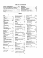
TABLE OF CONTENTS
OPERATION
................................................... 10-14
SERVICE AND ADJUSTMENTS
..............18-24
STORAGE .....................................................
25
TROUBLE
SHOOTING
.................................
26
SAFETY RULES ....................................................2,3
PRODUCT
SPECIFICATIONS
..............................
4
CUSTOMER
RESPONSIBILITIES
.......4,15-!7
WARRANTY
.......................................................................
4
TABLE OF CONTENTS
.............................................
5
REPAIR PARTS (SNOW THROWER).,.
28-37
INDEX ........................................................................................
5
REPAIR PARTS (ENGINE) ....................
38-42
ASSEMBLY
.............................................................6-9
PARTS ORDERING/SERVICE
..........................44
INDEX
A
F
Adjustment:
Auger Shear Bolt ...................................
23
Fuel, Type ......................................................
4, 12
Belt .....................................................................
19,20
Belts ..................................................
19,20
Fuel, Storage .................................!2, 25
Belt Guide .................................................
21
Friction Wheel:
Friction Wheel ................................
21,22
Cable .......................................................
19
S
Adjustment .............................................
21
Carburetor ..............................................
23
Safety Rules .................................................
2, 3
Replacement ........................................
22
Friction Wheel ...............................2o,2I
G
Service and Adjustments:
Spark Plug .....:...........................................
23
Gears:
Auger Housing Height ..................
7, 18
Traction and Auger ........................
19,20
Auger Shear Bolt .......................................
23
Auger Gear Box ...............................I7
Assembly:
Belts .........................................................
19-20
Hex Shaft ..................................................
17
Belt Guide ..................................................
21
Crank Assembly .......................................
8-9
H
Shifter Lever ............................................
9
Belt Replacements ...............................
20
Handle, Upper and Lower ........................
7
Skid Height Adjustment ................7, 19
Cable
7, 9, 19
Height Adjust Skids ..........................
7, 18
Unpacking .................................................
7
Hex Shaft ........................................................
t7
Carburetor ...............................
13,23, 25
B
I
Friction Wheel ............................21, 22
Belts:
Spark Plug ....................................... 24
Ignition, Key .................... 10, 11, I3, 14
Service Recommendations .................
25
Adjust Belts .....................................
19,20
Index .........................................................
5
Bett Guide Adjustment ....................21
L
Spark Plug ...........................................
17, 24
Replace Belts ..................................20
Levers:
Specifications ..................................................
4
C
Speed Governor ............................. 23
Auger Drive Ctutch .............
7, 10, tl, 19
Cables, Ciutch ..................................
7, 9, 19
Starting the Engine:
Choke ................................
!0, tl, 13, 14
Carburetor: ......................................................
24
Recoil Start ...............................................
13
Shifter ..............................................
9, 10, 11
Choke .................................10, tl, 13,14
Stopping the Engine ......................13, 14
Throttle Control ..................
I0, t 1, I3, t4
Clutch, Levers .........................................
1O,11
Traction Drive Clutch .... 7, 10, ! I, 19
Stopping the Snow Thrower ................
11
Controls:
Lubrication:
Shipping Carton ............................ 6, 7
Engine ....................................
10, 11, 13, 14
Skid Height ................................... 7, 18
Auger Gear Box ......................................
17
Snow Thrower .....................................
t0
Shifter Lever ...........................................
9-11
Auger Shaft ................................................
16
Crank:
Shear Bolts ...................................... 23
Disc Drive Plate ...........................................
16
Adjusting Rod ....................................
8, 18
Storage .................................................25
Engine .......................................
12,17,25
T
Assembly .....................................................................
8
Hex Shaft and Gears ............................
17
Table of Contents ....................................
5
Operation .............................................................
11
Customer Responsibilities ...........
4,15-17
O
Trouble Shooting Chart ..........................
26
Agreement ....................................................
4
Oil:
Toolsfor Assembly ...............................
6
Auger Gear Box .....................................
17
Traction Drive Belt ..................
19, 20
Engine .........................................
4, 12, 17
Tire Pressure .................................
18
Auger Shaft .........................................
16
Extreme Cold Weather .................
12,17
Engine ................................................t 7
Storage ..........................................................
25
General Recommendations ................
16
W
Type .....................................................
4, 12, 17
Hex Shall and Gears ............................
I7
Warranty .........................................................
4
Operation:
Wheel, Lockout Pin ............................ t2
Engine Controls ................
10, 11, 13,14
D
Operating Snow Thrower.., tt, 12, 15
Drive, Auger ....................................................
1t
Lockout Pin, Wheel ...............................
12
Drive, Traction ...........................................
11
Operating Tips .......................................
14
Deflector, Snow Chute .............................
11
Starling the Engine, Electric ...............
t3
Starting the Engine, Recoil .................
14
E
Snow Thrower Controls ....................
10-12
Engine:
Control ................................
10, 11, I3, 14
P
Oil Cap ....................................................
12, t7
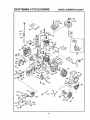
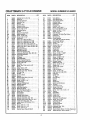
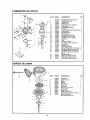
Paris ..............................................................
28-42
Oil Change ...................
_
................16
Primer Button .............................
10, 1t, 13
Oil Level .......................
:_....................
12, 17
R
Oit Type .................................................
4, 12, 17
Repair/Replacement Parts ............28-42
Speed Governor ........................................
26
Recoil Starter .....................................13
Starling, Electrically .........................13
Replacements:
Starling, Manually ..................................
t4
Storage ...................................................
25
...................................................
5
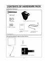
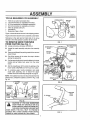
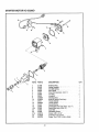
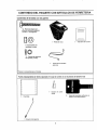
RE PACK
CONTEN rs OF HAR
CONTENTS
OF PARTS
BAG
*2 - Spare Shear Bolts
(1/4-20 x I-3/4 In)
D@
1 - Knob With Threads (not shown actua! size)
"2 - Spare Spacers
*2 - Spare 1/4 - 20 Locknuts
1 _ Owner's manua!
actual size)
"Non-Assembly
Parts packed
(not shown
1 - Starter Motor Cord (not
shown ac_ua_size)
Parts,
separately
in carton (not shown
full size)
q
I
l
r
I
I
1 - Parts Bag
I - 5W30 container oil
2 - Ignition
Keys (Attached
t - Crank Assembly
6
to engine
in plastic
bag)
ASS
TOOLS
REQUIRED
LY
FOR ASSEMBLY
i
i
iii,i i
i
LOWEF
122 2111-
Knife (to cut carton and plastic ties)
1/2 inch wrenches (or adjustable wrenches)
9/16 inch wrenches (or adjustable wrenches)
3/4 inch wrenches (or adjustable wrenches)
P_iers(to spread cotter pin)
Screwdriver
Measuring Tape or Ruler
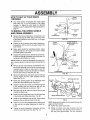
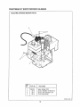
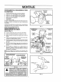
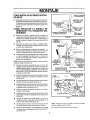
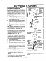
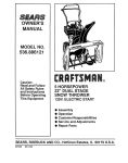
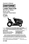
Figure 1 shows the snow thrower in the shipping position.,
SHIFTER
PLATE
UPPER
HANDLE
ASSEMBLY
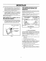
Figure 2showsthe snowthrower completely assembled.
Reference to the right and left hand side of the snow
thrower is from the operator's position at the handle,
TO REMOVE SNOW THROWER
FROM CARTON (See Fig. 1)
®
FIG. 1
Locate and remove container of 5W30 oil
TRACTION
®
Locate the crank assembly and place the assembly
aside
®
Remove anddiscardthe packing material from around
snow thrower.
®
Cut all four corners of the carton from top to bottom
and lay the panels fiat,
®
Cut ties securing the clutch control cables to the lower
handle and lay cables back away from the motor
frame
®
Roll the snowthrower off the carton by pulling on the
lower handle,, CAUTION: DO NOT back over cable
®
To complete upper handle installationand install
chute crank assembly, see To Install The Upper
Handle and Crank Assembly paragraph on page 8
AUGER DRIVE
LEVER
SHIFTER
LEVER
CHUTE
DEFLECTOR
NOTE: Ifthe cables have become disconnected from the
clutch levers, reinstall the cables as shown in Fig 3 and
Fig, 3A,,
4" LG FREE
STATE
TRACTION
DRIVE,.
_
"t_,
FIG. 2
/
""-
HEIGHT ADJUST
SKID
3" LG FREE
STATE
[ r%
DRIVEll _/_
DRIVE
LEVER
/
,q
H
--
AUGER
DRIVE
- $ '_L_.4"'DR_VE
SPRING_
_
LEVER
If
FION
DRIVE
LEVER
"Z'FITTING
SPRING
°ABLE
FIG. 3A
,_
SNOW FROM
CAUTION:
IF ANY
YOUGRAVELED
ARE REMOVING
OR UNEVEN SURFACE, RAISE THE FRONTOF
THE SNOW THROWER BY MOVING THE
SKIDS DOWN° THIS WILL HELP TO PREVEN_
STONES AND OTHER DEBRIS FROM BEING
PICKED UP AND THROWN BY THE AUGER.
FIG. 3
7
ASSEMBLV
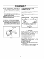
HOW TO SET UP YOUR SNOW
THROWER
UPPER
@ Your snow thrower is equipped with height adjust
skids (See Fig 2) on the outside of the auger
housing, To adjust the skid height for different
conditions, see To Adjust Skid Height paragraph on
page 18,
11f32"
X 2-3/4'"
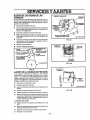
TO INSTALL THE UPPER HANDLE
AND CRANK ASSEMBLY
•
•
5/16"
LOCKWASHER
Remove the screws, flatwashers, Iockwashers, and
hex nuts securing the shifter plate in the lower holes
of the tower handle and move shift lever to 3rd gear
(See Fig 4A)
Raise upper handle into operating position Upper
handle should be to the outside of the lower handle
and shifter plate to the inside
I
Replace the right hand screw, flatwasher,iockwasher,
and hex nut throughthe handle and shifter plate Do
not tighten until all bolts are in place.
Remove the plastic bag, the plastic cap, the cotter pin
and the washer from the crank assembly and set
aside (See Fig 5)
I
Rotate the notched section of the discharge chute
toward the crank-adjusting rod (See Fig, 5),
ADJUST
NUTS TO
MOVE EYE BOLT IN
OUT
UPPER
HANDLE'_,
EYE
BOLT
NOTE: Unless you have the assistance of another per'son, it may be easier to install one side of the handle at a
time
i
Remove the 3/8" nylon Iocknut and flatwasher from
the eye bolt assembly (on the chute crank assembly
removed earlier). Check to make sure the two 3/8"
jam nuts are tight The jam nuts should be 2 75 inches
from the end o{ the eye bolt (See Fig 4B)
•
PLATE
FIG 4A
Loosen, but do not remove, the screws, flatwashers,
Iockwashers, and hex nuts in the upper holes of the
lower handle
I
FLATWASHER
NYLON
LOCKNUT
3/8 4
FLATWASHER
BOOT
ADAPTER
318""
FLATWASHER
FIGo 4B
PLAST,C
\
CAP
.NOTC.E{ SECTiON
\
COTTERtt,,,,'_ t18
- PiN
INCH CLEARANCE_
_,,_
@ Install the wormed end of the crank throughthe hole
in the adjusting rod and secure the end with the
flatwasher and cotter pin, as shown in Fig 5
@ Bend the ends of the cotter pin around the rod and
reinstall the plastic cap.
FLA
L<.
i
_
\, ".. .//S"'._
_/zINCH
•
install eye bolt throughlower hole in theleft hand side
of the handle and shifter plate (See Fig 4B)
I
install the 3/8" tlatwasher and the 3/8" nylon Iocknut
loosely on the eye bolt as shown in Fig 4B
RG_ 5
I
Tighten nut on eye boft installedearlier, keeping eye
in line with the rod while tightening the inside securely
NOTE: Make sure the cabtes are not caught between the
upper and lower handle
•
Tighten two upper handle bolts
i
Tighten the screw, flatwasher, lockwasher and hex
nut at the tower right hand hole (See Fig 4A)
•
8
Rotate the chute crank fully clockwise and tully
counter-clockwise The discharge chute should rotate futly with approximately 1/8 inch clearance
ASSE
LY
TO CHECK/ADJUST
CONTROL CABLES
@ Rotate the chute crank fully clockwise and fully
counter-clockwise. The discharge chute should rotate fully with approximately 1/8 inch clearance betweenthe worm and the bottom of the notch (See Fig.
The control cables, Fig. 7, attached to the auger clutch
lever and traction clutch lever may need to be adjusted
before you use your snow thrower.
5)
®
If the chute crank needs to be adjusted, go to lhe
Service and Adjustments section on page 18.Screws
securing chute clips at the base of the chute should
be slightly loose for easy rotation.
For instructions on checking or adjusting the control
cabies, see ToAdjust Clutch Contro_Cables paragraph on
page 19.
NOTE: Be sure the crank does not touch the side of the
engine or the cover will be scratched
TO INSTALL SHIFTER
®
CLUTCH
TRACTION CLUTCH LEVER
AUGER CLUTCH LEVER
LEVER KNOB
Thread the shifter lever knob ontothe threaded end
of the shifter lever until it is snug against the hex nut
and the lip is pointed toward Ihe engine. Tighten the
hex nut against the bottom of the shift lever knob (See
Fig. 6)..
CONTROL CABLES
SHIFTER KNOB
FIG.7
4'
CHECKLIST
BEFORE YOU OPERATE AND ENJOY YOUR NEW
SNOW THROWER, WE WISH TO ASSURE THAT YOU
RECEIVE
THE BEST
PERFORMANCE
AND
SATISFACTIONFROM THISQUALt7-YPRODUCT
LEVER
PLEASEREVIEW THEFOLLOWING CHECKLIST:
FIG. 6
,l
A_Iassemblyinstructions
have been completed
/
The discharge
chute rotates freely
carton
WHILE LEARNING HOW TO USE YOUR SNOW
THROWER, PAY EXTRA ATTENTION TO THE
FOLLOWINGIMPORTANTITEMS
/
No remaining loose parts in
/,/' Engine oilis at proper level
/4' Make sure gas tank is filled properly with clean, fresh,
unleaded
gasoline,
v'/ Become familiar with all controls-their ]ocation and
function Operate controls before starting engine
9
u,l/,
OPERATION
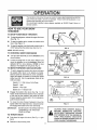
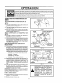
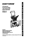
KNOW YOUR SNOW THROWER
READ THIS OWNER'S
MANUAL AND SAFETY RULES BEFORE OPERATING
YOUR SNOW
THROWER_
Compare the illustrations with your snow thrower to familiarize yourself with the location of various
controls and adjustments. Save this manual for future reference,
TRACTION DRIVE
LEVER
LEVER
SPEED SHIFTER
LEVER
CRANK
ASSEMBLY
CHUTE DEFLECTOR
--..
IMER BUTTON
STARTER
DISCHARGE,
CHUTE
KEY
STARTER
HANDLE
CHOKE CONTROL
THROTTLE CONTROL
SCRAP ER BAR
ADJUST SKIDS
FIG. 8
SEARS SNOW THROWERS conform to the safety standards of the American National Standards Institute, B71,,3-1984
DISCHARGE CHUTE - Changes the direction the snow
is thrown
HEIGHT ADJUST SKIDS- Adjusts the ground clearance
of the auger housing.
IGNITION KEY - Must be inserted to start the engine,
RECOIL STARTER HANDLE- Starts the engine manually
CHOKE CONTROL - Used to start a cold engine
PRIMER BUTTON - injeclsfuel directiy into the carburetor manifold for fast starts in cold weather
THROTt-LE CONTROL - Controls the engine speed
AUGER DRtVE LEVER * Starts and stops the auger and
impeller (snow gathering and throwing),
TRACTION DRIVE LEVER- Propels the snow thrower
forward and in reverse
SPEED SHIFTER LEVER - Selects the speed ol the
snow thrower (6 speeds forward and 2 speeds reverse).
CRANK ASSEMBLY - Changes the direction of snow
throwing through the discharge chute
CHUTE DEFLECTOR - Changes the distance the snow
is thrown,_
10
OPE
TlO
The operation of any snow thrower can result in foreign objects being thrown into the
eyes, which can result in severe eye damage Always wear safety glasses or eye
shields while operating the snow thrower.
We recommend standard safety glasses available at SEARS Retail Stores or
Service Centers.
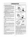
HOW TO USE YOUR SNOW
THROWER
WING KNOB
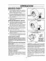
TO STOP YOUR SNOW THROWER
@ To stopthrowing snow, release the augerdrive lever
(See Fig° 11).
@ To stop the traction drive, release the traction drive
lever. (See Figure 1!)
®
To stop the engine, push the throttle control lever to
STOP and pull out the ignition key (See Fig 10)
FIG, 9
NOTE: DO NOT turn key.
ELECTRIC
TO CONTROL
•
SNOW
PRIMER BUTTON
\
DISCHARGE
BUTTON
Turn the crank assembly to set the direction of the
snow throwing
O
Loosen the wing knob on the chute deflector and
move the deflector to set the distance. Move the
deflector UP for more distance, DOWN for less
distance° Then tighten the wing knob (Fig 9).
TO MOVE FORWARD
AND BACKWARD
0
To shilt, release the traction drive lever and move
the speed shifter lever to the speed you desire.
Ground speed is determined by snow conditions.
Select the speed you desire by moving the speed
shifter lever left into the appropriate notch on the
shift lever plate:
CONTROL
/
THROTTLE
CONTROL
STARTER
HANDLE
FIG, 10
TRACTION DRIVE
LEVER
Speeds 1,2 _Wet, Heavy, Extra Deep
AUGER DRIVE
LEVER
Speed 3 - Light
Speed 4 - Very Light
Speeds 5, 6 - Transport only
O
®
Engage the traction drive lever (See Fig. 11, teft
hand), As the snow thrower starts to move, maintain
a firm hold on the handles, and guide the snow
thrower along the clearing path Do not attempt to
push the snow thrower
ON
LEFT
HAND
To move the snow thrower backward, move the
speed shifter lever right into first or second reverse
and engage the traction drive lever (left hand)
IMPORTANT:
TO THROW
FIG. 11
NEVER MOVE THE SPEED SHIFTER
LEVERWHILE THE TRACTION
LEVER IS DOWN
CAUTION: READ OWNER'S MANUAL
BEFORE
OPERATING
MACHINE.
NEVER DIRECT DISCHARGE TOWARD
BYSTANDERS_ STOP THE ENGINE BE-,
FORE UNCLOGGING
DISCHARGE
CHUTE OR AUGER HOUSING AND BEFORE LEAVING THE MACHINE,
SNOW
O
Push down the auger drive lever (See Fig 11, right
hand)
O
Release to stop throwing snow
'_
11
OPERATION
TO USE WHEEL LOCKOUT
PIN
•
The left hand wheel issecured to the axle with a klick
pin (See Fig., 12A), This unit was shipped with this
klick pin in the locked (through wheel hole) position
•
•
Forease of maneuverability in light snowconditions,
disconnect the klick pin fromthe wheel locked position
and push into the single wheel drive (unFockedaxle
hole only) position (See Fig, 12B)
II
KLICK PIN
Make sure that the klick pin is in the single wheel
drive position of the axle only and not through the
locked position
BEFORE
•
LOCKED
POSITION
STARTING
2-WHEEL
THE ENGINE
If the snow thrower must be moved without the aid of
the engine, it is easier to putlthe snow thrower by the
handles rather than pushing
KUCK PIN
Before you service or start the engine, familiarize
yourself with the snow thrower, Be sure you
understand the function and location of all controls
UNLOCKED
POSITION
NOTE: Check tension of clutch cables before starting the
engine (See To Adjust The Control Cables paragraph on
page 19),
•
Be sure that all fasteners are tight
•
Make sure the height adjust skids are properly
adjusted (See To Adjust Skid Height paragraph on
page 18),
•
Check tire pressure (14 to 17 pounds) See side of
tirefor maximum inflation Do not exceed maximum
pressure
DRIVE
FIG. 12A
SINGLE WHEEL DRIVE
FIG+ 12B
OIL FILL CA'PID|PSTICK
FILL OIL:
This snow thrower was shipped with a container of
5W30 oil This oil must be added to tile engine before
operating Remove the oil fill cap!dipstick and fill the
crankcase to FULL line on dipstick (21 ounces) (See Fig
NOTE: OIL LEVEL MUST
BE BETWEEN FULL
AND ADD MARK
14)
NOTE: Engine may already contain some residual
oil Check frequently when filling the crankcase, Do
not over.fill
FIG.13
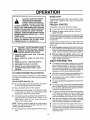
WARNING: Experience indicates that alcohol blended
fuels (called gasohot or those using ethanol or methanol)
can attract moisture which leads to separation and formation of acids during storage the fuel syslem of an engine
while in storage Acidic gas carl damage the fuel system
of an engine while in storage,
Tightenthe fill cap/dipstick securely each time you check
the oil level
NOTE: Oil must be changed after the first 2 hours of
operation to extend engine life
To avoid engine problems, the fuel system should be
emptied before storage for 30 days or longer, Start the
engine and let it run until the fuel lines and carburetor are
empty Use the carburetor bowl drain to empty residual
gasoline from the float chamber (Fig, 37, page 25) Use
fresh fuel next season (See Storage instructions on
page 25 for additional information,)
For extreme cord operating conditions of 0°F and below,
use a partial synthetic 0W30 motor oil for easier starting.
FILL GAS:
Fill the fuel tank with clean, fresh, unleaded grade
automotive gasoline Be sure that the container you pour
the gasoline from is clean and free from rust or other
foreign particles, Never use gasoline that may be stale
from long periods of storage in the container
Never use engine or carburetor cleaner products in the
fuel tank or permanent damage may occur
12
O E ATION
TO STOP ENGINE
O
CHOKE
CONTROL
To stop engine, move the throttle control lever to
STOP position and remove key. Keep the key in a
safe place. The engine will not start without the key.
TO START ENGINE
(Electric
•
START
ELECTRIC
BUTTON
Starter)
Be sure that the engine has sufficient oil The snow
thrower engine Jsequipped with a 120 voll AC. electric
starter and recoil starter_.Before starting the engine, be
certain that you have read the following intormatfon:
COLD
PRIMER
BUTTON
IGNITION
KEY
(See Fig. 14)
RECOIL
STARTER
THROTTLE CONTROL
Be sure the augerdrive and traction drive levers are
in the disengaged RELEASED position.
FIGo14
@ Move the throttle control to RUN position
O
Remove the keys from the plastic bag. Insert one
key intothe ignition slot Be sure it snaps into place
DO NOT TURN KEY Keep the second key in a safe
place
_
AND CAUTION MUST BE USED WHEN
AUTION: GASOLINE IS FLAMMABLE
HANDLING OR STORING IT,
DO NOT FILL FUEL TANK WHILE SNOW
THROWER IS RUNNING,WHEN IT IS HOT, OR
WHEN SNOW THROWER IS IN AN ENCLOSED
AREA,
@ Rotate the choke knob to FULL choke position
O
Connect the power cord to the switch box on the
engine.
O
Plug the olher end of the power cord into a threehole, grounded 120 volt A.C. receptacle.
KEEP AWAY FROM OPEN FLAME OR AN ELECTRICAL SPARK AND DO NOT SMOKE WHILE
FILLING THE FUEL TANK,
O
Push the primer button while covering the vent hole
as follows: (Remove finger from primer button
between primes).
NEVER FILL THE TANK COMPLETELY, FILL
THE TANKTOWlTHIN 1/4"-1f2" FROMTHETOP
TO PROVIDE SPACE FOR EXPANSION OF FUEL
Do not prime if temperature is above 50°F
ALWAYS FILL FUEL TANK OUTDOORS AND
USE A FUNNEL OR SPOUT TO PREVENTSPILL.
ING,
Two times if temperature is 50°F to 15°F.
Four times if temperature is below 15°F.
MAKE SURE TO WIPE UP ANY SPILLED FUEL
BEFORE STARTING THE ENGINE,
@ Push down on the starter button until the engine
starts.. Do not crank for more than 10 seconds at a
time., This electric starter is thermally protected I1
overheated it will stop aulomatically and can be
restarted only when it has cooled to a safe
temperature (a wait of about 5 to 10 minutes is
required).
O
When the engine starts, release the starter button
and slowly rotate the choke to OFF position. If the
engine falters, rotate the choke to FULL and then
gradually to OFF
•
Disconnect the power cord from the receptacle first
and then from the switch box on engine,.
STORE GASOLINE IN A CLEAN, APPROVED
CONTAINER AND KEEP THE CAP IN PLACE ON
TH E CONTAINER.
NOTE: Allow the engine to warm up for a few minutes
because the engine will not develop full power until il
reaches operating temperature
O
Run the engine at fufi throttle RUN when throwing
snow,
13
iiiii,
OPERATION
WARM
CAUTION: NEVER RUN ENGINE
START
If restarting a warm engine alter a short shutdown, rotate
choke to OFF instead of FULL and do not push the
primer button.
,_
INDOORSVENTILATED
OR IN ENCLOSED,
POORLY
AREAS.
ENGINE EXHAUST CONTAINS
CARBON MONOXIDE, AN ODORLESS AND
DEADLY GAS. KEEP HANDS, FEET, HAIR AND
LOOSE CLOTHING AWAY FROM ANY MOVING
PARTS ON ENGINE AND SNOW THROWER.
WARNING: TEMPERATURE OF MUFFLER AND
NEARBY AREAS MAY EXCEED 150° F. AVOID
THESE AREAS°
DO NOT ALLOW CHILDREN OR YOUNG TEENAGERS TO OPERATE OR BE NEAR SNOW
THROWER WHILE IT IS OPERATING.
FROZEN
STARTER
If the starter is frozen and will not turn engine:
@ Pull as much rope out of the starter as possible.
@ Release the starter handle and let it snap back
against the starter.
If the engine still fails to start, push the primer button two
or three times again and repeat the two previous sleps
until the engine starts Then continue with the directions
for cold start
To help prevent possible freeze-up of recoil starter and
engine controls, proceed as follows after each snow
removal job
CAUTION: DO NOT ATTEMPT TO REMOVE ANY ITEM THAT MAY BECOME
LODGED IN AUGER WITHOUT TAKING
THE FOLLOWING PRECAUTIONS:
•
With the engine running, pull the starter rope hard
with a continuous full arm stroke three or four times
Pulling of starter rope will produce a loud clattering
sound. This is not harmful to the engine or starter.
• RELEASE AUGER DRIVE AND TRACTION
DRIVE LEVERS.
•
With the engine not running, wipe all snow and
moisture from the carburetor cover in area of control
levers Also move throttle control choke control, and
starter handle several times.
• MOVE THROI3FLE LEVER TO STOP POSITION,
SNOW THROWING TIPS
• REMOVE (DO NOT TURN) IGNITION KEY,
• DISCONNECT SPARK PLUG WIRE.
®
For maximum snow thrower efficiency in removing
snow, adjust ground speed, NEVER the throttle= Go
slower in deep, freezing, or wet snow. If the track
slips, reduce forward speed The engine is designed
to deliver maximum pedormance at full throttle and
should be run at this power setting at aUtimes.
TO START ENGINE (Recoil Starter)
•
Be sure that the engine has sufficient oil. Belore starting
the engine, be certain that you have read the following
information:
Most elficient snow throwing is accomplished when
the snow is removed irnmediately after it falls..
•
For complete snow removal, slightly overlap each
path previously taken
COLD START (See Fig. 14)
•
The snow should bedischarged down wind whenever
possible.
•
For normal usage, set the skids so that the scraper
baris 1/8" above the skids. Forexlremely hardpacked
snow surfaces, adjust the skids upward so that the
scraper bar louches the ground
• DO NOT PLACE YOUR HANDS IN THE
AUGER OR DISCHARGE CHUTE. USE A
PRY BAR°
•
Be sure the auger drive and the traction drive levers
are in the disengaged RELEASED position
O
Move the throttle controlto RUN position
O
Pull the starter handle rapidly Do not allow the handle
to snap back, but allow it to rewind slowly while
keeping a firm hold on the starter handle.
•
As the engine warms up and begins to operate eve nly,
rotate the choke knob slowly to OFF position If the
engine falters, return to FULL choke, then slowly
move to OFF choke position
On gravel or'crushed rock surfaces, set the skids at
1-1/4" below the scraper bar (see To Adjust Skid
Height paragraph on page 18) Stones and gravel
musl not be picked up and thrown by the machine.
•
After the snow throw!ng job has been completed,
allow the engine to idle for a few minutes, which will
melt snow and accumulated ice off the engine.
®
•
Clean the snow thrower thoroughly after' each use.
Remove ice and snow accumulation and all debris
from the entire snow thrower, and flush with water (if
possible) to remove all salt or other chemicals Wipe
snow thrower dry
•
NOTE: Allow the engine to warm up for a few minutes
because the engine will not develop full power until it
reaches operating temperature
•
Run the engine at or neat thetop speed whenthrowing
snow
14
GUSTO E
ES
PaN
S
B/IIII'IIIIIII/Ij1/11¸¸¸¸1111
ii LmTm
ES
ii iiiiiiiiiiii i iiiiiii
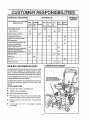
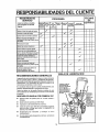
SERVICE
RECORDS
Fill in dates as you complete
regular service
SCHEDULE
SERVICE
DATES
iiiii
IIHIL II II
After Before As
Every Every Every Each
Before
First 2 Each Needed 5
t0
25
Season Storage
hours Use
Hours Hours Hours
Check Engine Oi! Level
,_
Change Engine Oil
,I_
Tighten All Screws and Nuts
_
_
_
V _'
!.,"
Lubricate All Pivot Points
v"
Lubricate Auger Shaft (See Shear
iBolt Replacement)
........
i.
Lubricate Disc Drive Plate Zerk (See
ICustomer Responsibilities}
Check Auger Clutch Cable
It'
Adjustment (See Cable Adjustment)
Check Traction Clutch Cable
Adjustment (See CableAdjustment)
Adjust Drive Belts
V 'I
,
,
Check Fuel
Drain Fuel
V,#
Replace Spark Plug
_
LUBRICATION CHART
GENERAL RECOMMENDATIONS
The warrantyon this snow thrower does not cover items
that have been subjected to operator abuse or negligence, To receive full value from the warranty, operator
must maintain snow thrower as instructed inthis manual,
Some adjustments will need to be made periodically to
properly maintain your snow thrower
Lubricate auger shafL
Coat with a clinging type
grease such as Lubr|plate or
fiber impregnated grease.,
All adjustments in the Service and Adjustments section of
this manual should be checked at least once each
season
AFTER
FIRST
USE
o
Check for any loose or damaged pads
®
Tighten any loose fasteners
•
Check and maintain the auger_
•
After each use, remove all snow and slush off the
snowthrowerto prevent freezing of auger or controls
®
Check controls to make sure they are functioning
properly,
•
tf any parts are worn or damaged,
immediately
replace
t5
=
l_
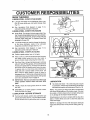
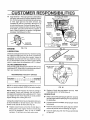
CUSTOMER RESPONSIBILITIES
lull
,JJl,i
SNOW THROWER
LUBRICATION
- EVERY
i
II
i
II i,illl
i lll
i _LL-
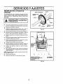
FIVE HOURS
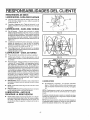
®
Lubricate the flange on the discharge chute every
five (5) hours during use and before storage (See
Fig 17),
•
See Lubrication Chart diagram on page 15 for
lubrication points and type of lubricant
LUBRICATION
- EVERY TEN HOURS
•
Auger Shaft- For storage, lubricate auger shaft ( See
Fig 16) with a clinging type grease such as Lubriplate,
When replacingshear bolts, remove shear bolts and
lubricate auger shaft (see To Replace Shear Bolt
paragraph on page 23)
•
The chute control rod, used to change the direction
of the snow discharge, needs to be lubricated
frequently and before storage (See Fig 17)
•
See Lubrication Chart diagram on page 15 for
lubricationpoints and type of lubricant
LUBRICATION
- EVERY
Position
•
Place a coin or (a shim of equal thickness) between
the rubber friction wheel and disc drive plate to
FIG. 15
LUBRICATEAUGER'SHAFT
FIG. 16
the friction disc
Disc Drive Plate- Using a hand grease gun lubricate
wit h a Hi Temp EP Moly grease, zerk iocated beneath
the disc drive plate (See Fig 18 inset) every 25 hours
and at the end of the season and/or before storage.
To grease zerk, turn disc drive plate clockwise by
hand until zerk is clearly visible at front cer_ter DO
NOT overfill or allow grease to come in wheel or
damagewill result Fill zerkontyuntiigrease
becomes
visible below bearing assembly located under grease
zerk See Lubrication Chart on page 15
CHUTE
FLANGE
FIG. 17
LUBRICATION
plate.
•
NOTE: Clean
disc hub.
t)
CAUTION: Do not allow grease to contact friction
wheel and disc drive plate
LUBRICATION
all excess
- BEFORE
grease
CONTROL
ROD
DISCHARGE
CHUTE
IMPORTANT: Remove coin and ensure that a gap
exists
between
friction
wheel and disc drive
®
®
AXLE _
speed selector lever in first gear
prevent friction wheel contacting
II
AXLE
25 HOURS
•
•
_
lound on friction
Hex Shaft and Gears - Hex shaft and gears requ[re
no lubrication All bearings and bushings are lifetime
lubricated and requireno maintenance (See Fig, 18),
NOTE: Any greasing or oiling of the above components
can cause contamination of the friction wheel If the disc
drive plate or friction wheel come in contact with grease
or oil, damage to the friction wheel will result
STORAGE
Remove both wheels, grease (any automotive type
grease) both axles (See Fig 15) and replacewheets.
Do this at least once a year and/or prior to storage,
Should grease or oil come in contact with the disc drive
plate or friction wheel, be sure to clean the plate and
wheel thoroughly.
NOTE: For storage, the hex shalt and gears should be
wiped with 5W-30 motor oil to prevent rusting (See Fig
18)
16
CUSTO
®
E
PONSI
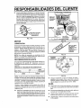
Auger Gear Box - The auger gear box is lubricated at
the factory and should not require additional lubrication if for some reasonthe lubricatant should leak out,
or if the auger gear box has been serviced, add
Lubfiplate No 630-AA or equivalent Maximum 3 1/4
ounces shouldbeused, Removefillerplug (Figure 17A) once a year,,If grease is visible, do not add If grease
is not visible, use a piece of fine wire like a dipstick, to
check if there is grease in the gearbox Add grease if
necessary Reinstall gear box filler
LITI
HEX SHAFT AND GEARS
WHEEL
(Require No
Lubrication)
DRIVE
PLATE
FRICTION
WHEEL
GREASE
ZERK
GAP BETWEEN
=RICTtON WHEEL
AND DISC DRIVE
GEAR
°
_
ENGINE
" FILLER
BOX
PLATE
-_' .........
I
PLUG
i
........
_GREASE
Point
BEARING
ZERK
FIG. 17-A
ASSEMBLY
at which
grease should
be visible
........
FIG. 18
LUBRICATION
Check thecrankcase oil level (See Fig 19) before staring
the engine and after each five (5) hours o! continuous
USerAdd SAE. 5W-30 motor oil as needed Tighten lilt
cap/dipstick securely each time you check the oil level
S_A,E, 5W-30 motor oil may be used to make starting
easier in areas where the temperature is 20° F or lower,,
_IL
.,/
_"
COLDER (€
5W30
VISCOSITY
32 °
I
1
"1_'_'3_'
-0_
"_eF"
MUST BE BETWEEN
FULL AND
f"
ADD
MARK
FIG. 19
OIL RECOMMENDATION
Only use high quality detergent oilrated with API service
classification SG Select the oil's viscosity grade according to your expecled operating temperature:
RECOMMENDED
LEVEL
OIL FILL CAP/
DIPSTICK
GRADES
)_WARMER
SAE30
NOTE: For extreme cold operating conditions of 0 ° F and
below, use partial synthetic 0W30 oil for easier starting
FIG. 20
O Replace oil drain plug and tighten securely, Refill
crankcase with S,A E 5W30 motor oil
NOTE: Although multi-viscosity oils improve starting in
cold weather, these mufti-viscosity oils will result in
increased oil consumption when used above 32_'F Check
your engine oil level more frequently to avoid possible
engine damage from running low on oil
SPARK
o
Change the oil after first two hours of operation and every
25 hours thereafter or at least once a year if the snow
thrower is not used for 25 hours (See Fig 20)
Make sure that the spark plug is tightened securely
into the engine,and the spark plug wire is attached to
the spark plug
o
If a torquewrench is available, torque plug to 18 to 23
foot pounds..
•
O
Clean the area around the spark plug base before
removal to prevent dirt from entering the engine
0
Clean the spark plug and reset the gap periodically
at 030 inch
Position snow thrower so that the oil drain ptug is
_owestpoint on the engine Remove oH drain plug
and oil fill cap/dipstick Drain oil into a suitable
container Oil will drain more lreely when warm
I7
PLUG
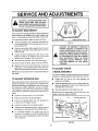
SERVICE AND ADJUSTMENTS
CAUTION: ALWAYS DtSCONNECTTHE
SPARK PLUG WIRE AND TIE BACK
AWAY FROM THE PLUG BEFORE MAKING ANY ADJUSTMENTS
OR REPAIRS.
SKID MOUNTING Nu_rs
TO ADJUST SKID HEIGHT
This snow thrower is equipped with two height adjustment
skids, located on the outside of the auger housing (See
Fig 2!)These
skids elevate the front of the snow thrower
For normal hard surfaces, adjust the skids as follows:
AUGER
HOUSING
iii
•
Check tire pressure (14 to 17 pounds) See sicle of tire
for maximum inflation Do not exceed maximum pressure on side of tire
•
Place the extra shear bolts supplied (found in parts
bag) under each end of the scraper bar near but not
under' the skid
•
Loosen the skid mounting nuts (See Fig 21) and
adjust the skids up to bring the front of the snow
thrower down Re-tighten the mounting nuts
Q
Set the skid on the other side at the same height
CAUTION:
BE CERTAIN TO MAINTAIN
PROPER GROUND CLEARANCE
FOR
YOUR PARTICULAR
AREA
TO BE
CLEARED. OBJECTS S UCH AS GRAVEL,
ROCKS OR OTHER DEBRIS, IF STRUCK
BY THE IMPELLER,
MAY BE THROWN
WiTH SUFFICIENT
FORCE TO CAUSE
PERSONAL
INJURY, PROPERTY
DAMAGE OR DAMAGE
TO THE SNOW
THROWER.
Raise the front of the snow thrower by moving the
skids down.. This will help prevent rocks and other
debris from being picked up and thrown by the auger
TO ADJUST CHUTE
CRANK ASSEMBLY
NOTE: Be sure that snow thrower is set at same height on
both sides
TO ADJUST
SCRAPER
If you cannot rotate the chute crank fully to the left and to
the right, you need to adjust the chute crank (See Fig 22)
BAR
After considerable use, the metal scraper bar will have a
definite wear pattern The scraper bar in conjunction with
the skids should always be adjusted to allow 1/8' between
the scraper bar and the sidewalk or area to be cleaned
The scraper bar may have to be returned to its original
lower setting to maintain the original performance level To
adjust:
•
Position the snow throweron a level surface
•
Make sure both tires are equally inflated
•
Loosen the carriage bolts and nuts securing the
scraper bar to the auger housing
i
Adjust the scraper bar to the proper position
•
Loosen both 1/2" nuts on the crank adjusting
(using 314" wrenches)
rod
•
Rotate the adjusting rod in or out to allow about 1/8"
clearance between the notch in the flange and the
outer diameter of the worm
•
Once this clearance
is set, tighten the nuts
NOTE: Be sure the crank does not touch the side of the
engine or the cover will be scratched.
PLASTIC _
CAP COTTERJ'_
@ Tighten the carriage bolts and nuts, making sure that
the scraper bar is parallel with the working surface
•
ADJ UST SKID
FIG. 21
For rocky or uneven surfaces, adjust the skids as follows:
•
HEIGHT
=l u=uu,
FL
For extended operation, the scraper bar may be
reversed If the scraper bar must be replaceddue fo
wear, remove the carriage bolts and nuts and install a
new scraper bar
PIN
1
NOTCHEDSECTION
" "_,_
\
18IN_..
_J"
LEARANCE
\'k.J'_.._I'2',NCH
FIG. 22
18
"_.
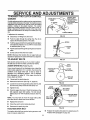
TO ADJUST THE CLUTCH C6'N'TROL
CABLES
CONTROL LEVER
MUST BE IN FULL
FORWARD POSITION
(Just Contacting
Plastic Bumpor) WHEN
CHECKING
AUGER
LEVER
Periodic adjustment of the cables may be required due to
normal stretch and wear on the belts, To check for correct
adjustment, the control lever must be in the full forward
position, resting on the plastic bumper,, The control
cables are correctly adjusted when the center of the "Z"
fitting is between the center and top of the hole in the
clutch lever and there is no droop in the cable (See Fig.
23)°
"Z"
FITTING
PLASTICBUMPER
If adjustment is necessary:
O
O
®
FIG. 23
Disconnect '_" Fitting from drive lever
Push the cable through the spring (See Fig 24) to
expose the threaded portion of the cable.
SPRING
Hold the square end of the threadedportion with pliers
and adjust the Iocknut in or out untilthe excess slack
is removed (See Fig,,24),,
®
Pullthe cable back throughthespring and connect the
cable.
O
Do the same for the other lever cable,
SQUARE
END
"LOCKNUT
NOTE: Whenever the traction drive or auger belts are
adjusted or replaced, the cables willneed tobe adjusted.
TO ADJUST
BELTS
FIG. 24
Belts stretch during normal user If you need to adjust
the belts due to wear or stretch, proceed as follows:
_
AUGER
DRIVE
BELT
_,_.
If your snow thrower will not discharge snow, check the
control cable adjustment, If it is correct, then check the
condition of the auger drive bell it may be loose or
damaged° If it is damaged, replace it, See To Replace
Belts paragraph on page 20 If the auger drive belt is
loose, adjust as follows:
@
AUGER
IDLER_
PULLEY
) _._.,_',_._
I/2INCH
.,
Disconnect the spark plug wire
/.,--. IMPELLER
_,,,.J
@ Remove the belt cover (See Fig, 27, page 20)°
®
DRIVE
(See Fig. 26)
PLILLEY
illlllllll
ii,,llll,i i
ii
i j
i
i
FIG. 25
Loosen the nut on the auger idler pulley (See Fig, 26)
and move the pulley toward the belt about t/8'L
AUGER
DRIVE BELT
@ Tighten the nut.
@ Press the auger drive lever Check the tension on the
belt (opposite auger idler pulley). The belt should
deflect about 1/2" with moderate pressure (See Fig.
25),
.TRACTION DRIVEBELT
BELT GUIDE
(Left Hand)
DRIVE
IDLER PULLEY
BELT GUIDE
(Right Hand)
NOTE: You may have to move the auger idler pulley
more than once to obtain the correct tension.
_ER IDLER
PULLEY
@ Replace the belt cover,
@ Check the clutch control cable adjustment.
@ Reconnect the spark plug wire
TRACTION
DRIVE
FIG. 26
BELT
®
The traction drive belt has constant spring pressure and
does not require adjustment
!9
Replace the tractiondrive belt if it is slipping (see To
Replace Belts paragraph on page 20)
TO REPLACE
BELTS
The drive belts on this snow thrower are of special
construction and should be replaced with original
equipment belts available from your' nearest Sears Store
or Service Center.
BELT
COVER
You will need the assistance of a second person while
replacing the belts,
/
Drain the gasoline from the fuel tank by removing the fuel
line.. Drain the gas and reinstall the fuel line.
i
5/8 INCH
CAUTION: DRAIN THE GASOLINE OUT- 1
DOORS, AWAY FROM FIRE OR FLAME.
X 112 INCH SELF
TAPPING SCREW
I
AUGER
DRIVE
FIG. 27
Hll
BELT
TRACTION DRIVE
j
iji
TRACTION DRIVE BELT
If your snow thrower will not discharge snow, and the
auger drive belt is damaged, replace it as follows:
•
•
DRIVE
BELT
Disconnect the spark plug wire._
Remove the belt cover (See Fig 27)
®
Loosen the belt guides (See Fig 28) and pull away
from the engine drive pulley
®
Loosen the nut on the auger idler pulley (See Fig 28)
and pull idler pulley away from the belt
•
Remove belt from engine drive pulley
•
Remove top two bolts securing auger housing to
motor mount frame. Loosen bottom two bolts, (See
Fig. 30, page 21).
•
BELT GUIDE
Remove brake arm from housing Do not remove
spring
•
Remove old belt from the auger drive pulley.
•
Install new replacement belt of the same type onto the
auger pulley.
•
Reinstall brake arm into housing Ensure brake arm is
fully inserted into housing and brake pad is riding in
pulley groove.
IDLER
PULLEY
TRACTION DRIVE
IDLER PULLEY
FIGo 28
Auger housing and motor mount frame will separate,
hinged by bottom two bolts.
•
DRIVE
PULLEY
BELT GUIDE
(Right Hand)
0
Disconnect the spark plug wire.
O
Remove the belt cover
O
Loosen belt guides and pull guides away from the
engine drive pulley.
0
Loosen nut on auger idler and pull auger idler pulley
away from belt.
O
Remove auger drive belt from engine pulley
O
Pull the traction drive belt idler pulley away fromthe
drive belt.
•
Position belt onto engine drive pulley°
O
Remove drive belt.,
®
Adjust the augerdrive belt (see ToAdjustAuger Drive
Belt paragraph on page 19).
0
Position new replacement belt ol the same type onto
traction pulley.
•
Adjust the belt guides (see ToAdjust The Belt Guides
paragraph on page 21)
O
®
•
Replace top two bolts Re-tighten bottom two bolts
Reinstall the belt cover,
Pull idler pulley away from belt, allowing belt to be
positioned onto engine pulley
O
Release idler pulley Ensure idler pulley is property
engaged with belt.
•
Checkthe clutch control cable adjustment (see page
19).
O
Reinstall auger drive belt on engine
O
Adjust belt guides and tighten the mounting screws
(see To Adiust The Belt Guides paragraph on page
2f).
O
Readjust auger idler to adjust beet.See page 19
0
Reinstall the belt cover.
@
Reconnect the spark plug wire
®
Reconnect the spark plug wire.
TRACTION
DRIVE
BELT
(See Fig. 28)
If your snow thrower will not move forward, check the
traction drive belt for wear, (Check other causes also in
the Trouble Shooting Points section.) 1Ithe traction drive
belt needs to be replaced, proceed as follows:
2O
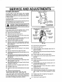
S RVIC AN
TO ADJUST
TS
THE BELT GUIDES
MOTOR MOUNT FRAME
e
Disconnect the spark plug wire,
e
Remove the belt cover by removing the screw and
flatwasheron the leftand right hand sides, See Fig, 27
page 20,
e
Engage the auger drive clulch lever
e
Measurethe distance between the belt guides andthe
belt (See Fig. 29), The distance should be 3/32" for
each guide.,
@
if adjustment is necessary, loosen the belt guide
mounting bolts° Move the belt guides to the correct
position. Tighten the mounting bolts
k
PANEL
AUGER
HOUSING
REMOVE
TOP
BOLTS
(EACH
SIDE)
\
LOOSEN BOTTOM BOLTS
(EACH SIDE)
(Botlom View)
,Lij
@
Reinstall the bell cover,
o
®
If adjustment is necessary, loosen the belt guide
mounting bolts, Move the belt guides to the correct
position, Tighten the mounting bolts
Reinstall the belt cover
O
Reconnect the spark plug wire.,
....
ADJU TM
_
_,,_f..._./1
It `
.................
FIG. 30
®
Move frictionwheel to proper positionas indicatedin
previousstep (Fig° 31A).,
O
Re-tightenbelts in speed selector level
®
Reinstallthe bottom panel
FRICTION
AUGER DRIVE PULLEY
DISC DRIVE
PLATE
BELT
O0,D
wtg.,.o.,)
if
/i / /J,.
,=,NO.
.._.L_..
{--"
_.._IMPELLER
)
PULLEY
FIG. 31A
FIG. 29
SPEEDSELECTOR
LEVER
TO ADJUST THE FRICTION WHEEL
If the snow thrower will not move forward, you need to
check the t raction drive belt, the traction drive cable orthe
frictionwheel If the friction wheeiis damaged, itwill need
to be replaced, See To Replace Friction Wheel paragraph on page 22 tf the friction wheel is not worn, check
the adjustment, as follows:
@
BOLT S
TO BE
Disconnect the spark plug wire,
OOSENED
@ Drain the gasoline from the gas tank,
•
(RearView t
Stand snow thrower on the auger housing end.
FIG. 3'1B
@ Remove the bottom panel (See Fig.,30).
•
Position the shifter lever in first (1) gear.
•
Note the position of the friction wheel on the disc drive
plate,.The right outer side of the disc drive plate should
be 3" from the center of the friction wheel (See Fig.
31A),
If 3dJustment Is necessary:
•
Loosen bolts in speed selector lever (See Fig 31B)
21
.qFRVICF AND A_r}JUSTMENFS
FR|CTION
WHEEL
TO REPLACE FRICTION WHEEL
Ifthe snowthrower will not move forward,and the friction
wheel is worn or damaged, you need to replace it as
follows: (First allow the engtne to cool.)
BOLT
LOCKWABHER
HEX
SHAFT
AWAY FROM FIRE OR FLAME,
!
BOLT
•
Drain the gasoline from the fueltank by removing the
fuel line Drain the fuel and reinstall the fuel line.
•
Disconnect the spark plug wire
•
Stand the snow thrower up on the auger housing end
(See Fig 33).,
•
Rerr_ve the bottom panel (See Fig,,30, page 21).
FIG. 32
®
Remove the three (3) fasteners securing the fnction
wheel to hub (See Fig..32) and set fasteners aside
FRICTION
•
Remove the four bolts securing the bearing plates
(both sides)
•
Remove right side bearing plate Leave Hex shaft in
original position (See Fig..33).
Rernove fdction wheetfrom hub Slipfrictionwheel off
hex shaft towards right side (See Fig 33)
®
•
Position new friction wheel onto hub,
•
Install bearing plates to original position Ensure hex
shaft is engaged with both bearing plates,
•
Secure bearing plates using bolts removed earlier.
•
Secure friction wheel to hub using fasteners removed
earlier. Ensure hex shaft turns freely,
LOCKWASHER
HUB
HUB
HEX SHAFT
FASTENERS
(screws,
Iockwashers
and nuts)
Replace bottom panel
•
Lowerthe snow thrower ontothe tires
RING
PLATES
;
NOTE: Ensure frictionwheel and friction disc are free
from grease or oil.
•
NUT
0
"\
•
//
i,....................................................................
ous,NG
(UNIT STANDING ON
AUGER HOUSING END)
j
Hi,ll
===ul,Jlu
FIG. 33
22
SE
CE
ADJUST
TS
TO REPLACE AUGER SHEAR BOLT
The augers are secured to the auger shaft with special
bolts (See Fig° 34) that are designed to break (to protect
the machine) if an object becomes lodged in the auger
housing. Use of a harder bolt will destroy the protection
provided by the shear boll
IMPORTANT; TO INSURE SAFETY AND
PERFORMANCE LEVELS, ONLY
ORIGINAL EQUIPMENT SHEAR
BOLTS SHOULD BE USED, WHEN
REPLACING SHEAR BOLTS, BESURE
TO REPLACE SHEAR BOLT
SPACERS.
AUGER
SHAFT
FIG, 34
To replace a broken shear bolt, proceed as iollows:
®
Move the throttleto STOP and turn off all controls,
®
Disconnect the spark plug wire. Be sure all moving
parts have stopped.
•
Remove the broken shear bolt.
•
Lubricate the augershaft by squirting oil into the shear
bolt hole in the auger shaft Then rotate the auger to
distribute the oil on the shaft..
e
Align the hole in the auger with the hole in the auger
shaft. Installt he newshearbolt, shearbolt spacer, and
locknut provided in parts bag
j
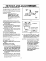
DLE ADJUSTING SCREW
(Close finger tight ordy)
@ Reconnect the spark plug wire_
TO ADJUST
BOWL DRAIN
CARBURETOR
Close the high speed adjusting screw by hand.
e
Do not over-tighten.
®
@ Close the idle adjusting screw by hand. Do not overtighten,.
Then open it 1-1/4 to 1-1/2 turns.
®
Start the engine and let it warm up.
@ Setthe throttle control to RUN Adjust the high speed
adjusting screw In until the engine speed or sound
alters_Adjust the screw out until the engine speed
sound alters.. Note the difference between the two
limits and set the screw in the middle of the range_
•
Let the engine run undisturbed for 30 seconds after
each setling to allow the engine to react 1othe previous adjustment.
®
Set the throttlecontrot to IDLE. Adjust the idleadjusting screw in until the engine speeddrops, then adjust
the screw out until the engine speed drops. Note the
difference between the two limits and set the screw in
the middle of the range.
If the engine tends to stall under toad or does
notacceterate from low speed to high speed
properly, adjust the high speed screw out in 1/8 turn
increments until the problem is resolved Let the
engine run for 30 seconds between settings..
IMPORTANT:
@ Then open it I-1/4 to 1-1/2 turns
®
HIGH SPEED ADJUSTING
SCREW
(Close finger tight only)
FIG. 35
The carburetor (See Fig. 35 and Fig 37(page 25) has
been pre-set at the factory and readjustment should not
be necessary. However, ifthecarburetor does need to be
adjusted, proceed as follows:
•
CARBURETOR
23
NEVER TAMPER WITH THE ENGINE
GOVERNOR, WHICH IS FACTORY
SET FOR PROPER ENGINE SPEED,.
OVER-SPEEDING THE ENGINE
ABOVE THE FACTORY HIGH SPEED
SETTING CAN BE DANGEROUS,
IF YOU THINK THE ENGINEGOVERNED HIGH SPEED NEEDS
ADJUSTING, CONTACT YOUR
NEARESTSEARS SERVICE CENTER,
WHICH HAS THE PROPER
EQUIPMENT AND EXPERIENCE TO
MAKE ANY NECESSARY
ADJUSTMENTS
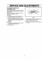
TO ADJUST OR REPLACE
THE SPARK PLUG
.030 GAP
Ifyou have difficultystartingyoursnow thrower,you may
need to adjust or replace the spark plug Follow the
instructions below°
Replace the spark plug if the electrodes are pitted or
burned or if the porcelain is cracked.
TO ADJUST:
•
Clean the spark plug by carefully scraping the electrodes (do not sand blast or use a wire brush)
FIG. 36
•
Be sure the spark plug is clean and free of foreign
material, Check the electrodesgap (See Fig 36) with
a wire feeler gauge and reset the gap to ,030 inchif
necessary
TO REPLACE:
•
If you need a new spark plug, use only the proper
replacement spark plug (See page 4)
•
Set the gap to .030.
24
•
Before installingthe spark plug, coat itsthreads lightly
with oil or grease to ensure easy removal
•
Tighten the plug firmly into the engine.
•
If a torque wrench is available, torque the plug to 18 to
23 ft - lbs,
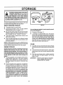
STORAGE
II_III_IUIllUI
IUI,IIIIIILU_JII
LI,IllLI,II
CAUTION: NEVER STORE YOUR SNOW
THROWER INDOORS OR IN AN ENCLOSED, POORLY VENTILATED AREA
IF GASOLINE REMAINS IN THE TANK. FUMES
MAY REACH AN OPEN FLAME, SPARK OR PILOT LIGHT FROM A FURNACE, WATER HEATER,
CLOTHES DRYER, CIGARETTE, ETCo
To prevent engine damage (if snow thrower is not used
for more than 30 days) follow the steps below,
SNOW
THROWER
FIG. 37
STORAGE
@ Thoroughly clean the snow thrower..
@ Lubricate all lubrication points (see the Customer
Responsibilities section on pages 15-17).
You can keep your engine In good operating condition during storage by:
@ Be sure that all nuts, bolts and screws are securely
fastened., inspect all visible moving parts for damage, breakage and wear. Replace if necessary.
®
Changing oil (See page 17).
e
Lubricating the piston/cylinder area,. This can be
done by first removingthe spark plug and squirtinga
few dropsof clean engine oil intothe spark plug hole.
Then cover the spark plug hole with a rag to absorb
oilspray,.Next, rotate the engine bypullingthe starter
rope fully out two or three times. Finally, reinstall
spark plug and attach spark plug wire.
@ Touch up all rusted or chipped paint surfaces; sand
lightly before painting,
e
Cover the bare metal parts of the blower housing
auger and the impeller with rust preventative, such
as a spray lubricant,.
NOTE,' A yearly checkup or tune-up by a SEARS Service
Center is a good way to insure that yoursnow throwerwill
provide maximum performance for the next season,
ENGINE
OTHER
Gasoline must be removed or treated to prevent gum
deposits from forming in the tank, filter, hose, and
carburetor during storage. Also during storage, alcohol blended gasoline that uses ethanol or methanol (sometimes called gasohol) attracts water. It acts
on the gas@line to form acids which damage the
engine.
e To remove gasoline, run the engine until the tank is
empty and the engine stops, Then drain remaining
gasoline from carburetor by pressing upward on
bowl drain located on the bottom of carburetor (See
Fig..37)°
®
e
If possible,store your snow thrower indoorswith gas
removed and cover it to give protection from dust and
dirt.
e
If the machine must be stored outdoors, block up the
snow thrower to be sure the entire machine is off the
ground.
e
Cover the snow thrower with a suitable protective
cover that does not retain moisture., Do not use
plastic or vinyl_
STORAGE
IMPORTANT:
tf you do not want to remove gasoline, a fuel stabilizer
(such as Craftsman Fuel Stabilizer No 33500) may
be added to any gasoline left in the tank to minimize
gum deposits and acids,. If the tank is almost empty,
mix stabilizer with fresh gasoline in a separate container and add some tothe tank, ALWAYS FOLLOW
INSTRUCTIONS ON STABILIZER CONTAINER,
THEN RUN ENGINE AT LEAST 10 MINUTES AFTER STABILIZER IS ADDED TO ALLOW MIXTURE TO REACH CARBURETOR. STORE SNOW
THROWER IN A SAFE PLACE. SEE WARNING
ABOVE.
25
NEVER COVER SNOW THROWER
WHILE ENGINE AND EXHAUST
AREAS ARE STILL WARM.
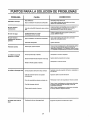
TROUBLE
CAUSE
CORRECTION
Difficult starting
Defective spark plug
Water or dirt in fuel system
Replace defective plug,
Use carburetor bowl drain to flush and refilf with fresh
fuel.
Engine runs erratically
Clean fuel line; check fuel supply; add fresh
Blocked fuel line or low on fuet
fuel (gasdiine/oil mixture if 2 cycle engine),
_,i,,,Jl,/llJl/,/
ii/,Jl,Jl,
Engine stalls
I
Engine runs erratically;
Move choke lever to OFF position
Unit running on CHOKE
JJl
U
Use carburetor bowl drain to flush and refiUwith fresh
Water or dirt in fuel system
fuel
Loss of power
Excessive vibration
Carburetor out of adjustment
Adjust carburetor
Loose parts; damaged impelter
Stop engine immediately and disconnect spark plug wire
Tighten all boils and make all necessary repairs If vibration
continues, have the unit serviced by a competent repairman
,,i
Unit fails to propel
Itself
Unitfails to
,J,l,ll,i,Jml,(i,
I,,J,L
Drive belt loose or damaged
Replace drive belt,
incorrect adjustment of traction
drive cable
Adjust traction drive cable
Worn or damaged frictionwheel
Replace friction wheel
Auger drive belt loose or damaged
Adjust auger drive belt; replace if damaged,
Auger controlcable not adjusted
Adjust auger control cable
dischargesnow
correctly
Shearbolt
broken
Replace shear boil
Discharge chute clogged
Stop engine immediately and disconnect spark plug wire
Clean discharge chute and inside of auger housing
Foreign object lodged in auger
Stop engine immediately and disconnect spark plug wire
Remove object from auger
26
NOTES
27
CRAFTSMAN 22" SNOW THROWER 536.886540
HANDLE A_-'EMBL¥
REPAIR PARTS
7
ASSEMBLY
LEFT SIDE
1
ASSEMBLY
RIGHT SIDE
12
17
_+_2 '_
t -%,"*"
I,,l_,,_Mll,
f
,
16
15
18
5
\
.,*.
.J
,.+r"
"r_+
RIGHTSIDE
NO
Z_
€
li
11
REE ITEM 1, PAGE32
LEFTSIDE
r REF+
PART NO+
9552-830
11234
120393
120638
120376
11261
307974
307974
t058
3535
4049
PART NAME
NO.
Handle, Upper
Screw, Hex, 5116-18 x 2-3/4 In
Ftatwasher, 1!/32 tn.
Lockwasher; Split 5/16 In
Nut, Hex, 5t16-18 Thd
Stop, Plastic,5/16
Traction Drive Lever; LH
Auger Drive Lever, RH
Pin, Clutch Handle Pivot
Nut, Push On Cap, 5116 In
Bumper, Handle
12
13
14
15
16
17
18
19
20
21
PART NO,+
1579
579869
1673
1502
308146
580667-830
180077
580639+854
235
330069
PARTNAME
Cable, Clutch
Spring, Drive Clutch LH
Spring, Auger Clutch RH
Nut, Hex NFI, 1/4-20 In
Boot, Clutch Spring
Handle, LowerScrew, HHC, 5/16-18 x 3/4 In
Shift Plate Bracket
Screw, HHC, 5/16-18 x 2.00 In
Owner's Manual
Indicates Standard Hardware items..
3'i 8782.314002 C
28
CRAFTSMAN
CHUTE
22" SNOW THROWER
CONTROL
536.886540
ROD REPAIR PARTS
/
5
I
7
6
\.
\
11
"\.
\
3
Ref.,Item -_°1_°
!_,. \
Page 28
19
2
18
18
\
/2
4
13
15
Page 28
_R_i
!
NO.
1
2
3
4
5
6
7
8
9
10
11
PART NO.
325608
120394
121224
104
307399
309312
578159
71457
148
308145
124829
REF.
NO.
12
_.3
14
!5
16
""7
18
19
2O
21
22
I
PART NAME
I PART NO.
_ 309344
Adapter, Boot to Handle
'. 71046
Nut, Hex Ny1318-16 Thd.
I
1162
Bracket,Chute Control RH
!
7052
Bracket, Chute Conlrol LH
I 309059
Bracket, Chute Rotate
' 70993
Bolt,Carriage, 5fl 6-18x3/4 In
| 120638
Lockwasher,Split, 5/16 In
1 120376
' Nut, Hex, 5/16-18 Thd
I
7055
Rod, Chute Control
_
7058
Nut, Hex Jam, 1/2-20 ThcJ.
I 120384
Lockwasher, Sp!it, 1/2 in.
Indicates Standard Hardware Items,
PART NAME
Crank& Worm Assembly
Flatwasher, 406x 81x 066
Pin, Cotter
Cap, Plastic
Handle Grip, Chute Control Rod
Flatwasher, 39x 70xO5
Ring, Retainer
Bolt, Eye
Grommet, Eye Bolt
Boot, Eye Bolt, Chute Crank
Nut, Hex Jam, 3/8-16 Thd_
3190443140080
29
CRAFTSMAN
22" SNOW THROWER
REE
NO.
PART NO,
PART NAME
1
2
3
4
5
6
7
8
9
10
1I
t2
13
t4
15
583124
577400
71371
583219
582960
180077
120393
120638
120376
583!30-854
581395-853
3809
120392!
120380i
120375i
Pulley, Auger Drive
Screw, Set, 5/16-18 x 1/2 In,
Key, Square
Spacer, Sleeve
Balf Bearing Retainer
Screw, HHC 5/16-18 x 5/8 In
Flatwasher, 11/32 in
Lockwasher, Split, 5/16 In,
Nut, Hex, 1/4-20 Thd.
Housing, Auger Assembly
Blade, Scraper, 22 In
Boll, Carriage, 1/4-20x5/8 In
Flatwasher, 9/32x5f8 In
Lockwasher, Split, 1/4 In
Nut, Hex, 1/4-20 Thd
*
*
°
*
536.886540
!
|
REE
NO,
PART NO.
16
17
18
19
20
21
22
23
24
25
26
27
28
29
305203-830
305205-830
9524
3943
1502
9517
8619
9357
305938-854
305939-854
323825
1161
70993
49562
PART NAME
Auger, Assembly RH
Auger, Assembly LH
Screw, HHC, 1/4-20xl-314 trt.
Spacer, Sleeve
* Locknut, Hex, 1/4-20 Thd
Bearing, Flange
Nut, Wd FI, 5/16-18 Thd
Screw, Wa, 5/16-18x3/4 In
Ptate, Auger Side, LH
Plate, Auger Side, RH
B01t, Carriage, 1/4-20x 75 In
Skid, Heighl Adjust
Bolt, Carriage 5/16-18x3/4 In
Bearing
" Indicates Standard Hardware items
319028,313997G
3O
CRAFTSMAN
DISCHARGE
22" SNOW THROWER
CHUTE
REPAIR
536.886540
PARTS
1t
!i
Re! Item No 10,
Page 3O
REF.
NO.
PART NO.
1
2
3
4
5
6
7
8
9
10
11
12
t3
I4
t5
I6
'17
307665
308931
58208
302680
'1498
302843
13527
120376
307698
180016
120392
!502
302183-830
85480
309057
71032
71058
PART NAME
Upper Chute Deflector
Wire, Chute Hinge
Screw, 5/16-18x3/4 In., SltrMa
Flatwasher, o312x73x.065
Locknut, Hex, 5/16-18 Thd
Bolt, Carriage, 5/16-18x1-1/4 in.
Knob, Tee
* Nut, Hex, 5/16-18 Thd
Lower Chute
Screw, HHC, 1/4-20xl/2 In.
Flatwasher, .286x 63x.065
' Locknut, Hex, 1/4-20 Thd.
Ring, Lower Chute
Clip, Chute Retainer
Clip, Chule Retainer w/Stop
Screw, WahMa, #8-32xl/2 In
Locknut, Hex, #8-32
Indicates Standard Hardware Items
31
319029,313998 A
CRAFTSMAN
FRAME
22" SNOW THROWER
COMPONENTS
REPAIR
536.886540
PARTS
Ref. Item No. 1,
_e33
11
13
2O
17
16
18
REF. I
NO. !
PART NO.
583052-854
910828
71100
35498
583031-830
310169
313854
71074
313853
-
=
.I
|
6
I
8
I
.q
I
lO
I 580889
11
I
12
13
I 73801
I 53697
14
I 579856
15
16
17
18
I 180124
I 120394
I 313843
I 41529
579874
REF.
NO.
PART NAME
Frame
Screw, 5/16-24xl O0 In
Locknut,HexWdFl, 5/16-24 Thd
Screw, WaTap, 5/!6-t8x3/4 ln_
Panel, Bottom
Screw, WaTap, 1!4-20x518 In_
Spring, Idler Traction Drive
Flatwasher, ,53xl 06x,095
Bearing, Flange
Shaft Auger Clutch, Assy
Lever, Auger Clutch
Pin, Spring 165 DIA x.88 LG
Nut, Push On
Cable, Clutch
Screw, HHC, 3/8-16x1-1/4 In.
Flatwasher, A06x.81x _066
Pulley, Idler
Locknut, Jam, 3/8-16 Thd.
19
20
21
22
23
24
25
26
27
28
29
30
31
32
33
34
35
PART NO.
579860
9524
120392
1502
580944
3809
120393
1502
580946
581540
318468
579872
180077
73795
579865
71038
580772
PART NAME
Spool, Cable Auger Clutch
Screw, HHC, 1/4-20xl-3/4 In.
Flat'washer,286x 63x .065
Nut, Hex Nyl, 1/4-20 Thd.
Cam, Brake Arm
Bolt, Carriage, 1/4-20x5/8 In
Flatwasher, .344x 69x 065
Locknut, Hex, 1/4-20 Thd
Rod, Brake Arm
Pad, Brake
Spring, Tension
Lever, idler Arm Traction
Screw, HHC, 5/16-18x3/4 In
F!atwasher, 328xl 38x.075
Bushing, Idler Lever
Nut, Hex Nyl, 5/16-18 Thd
Belt, Cover
3t8'790.313
32
-¢.._
3D
CRAFTSMAN 22" SNOW THROWER 536.886540
ENGINE
COMPONENTS
REPAIR
PARTS
4
5
6
3
5
1!
12
4
REF. ITEM I8
PAGE 34
REF.
NO,
PART NO.
1
2
3
4
5
6
7
8
9
10
11
12
t3
14
302636
120638
3949
578733
579855
579861
579854
579932
313858
581264
313826
120382
39573
REF iTEM 1,
PAGE 30
PART NAME
Engine, Craftsman 14&95500i
(See Engine Repair Parts list)
Screw, HHC, 5/16-18x1-1/4 In.
Lockwasher, Split, 5/16x 58x. 08
Guide, Rod Belt RH
Screw, HHC, 5/16-24x5/8 In
Washer, Crankshaft
Flatwasher, .752x 9 lx.02
Pulley, Half V3L
Belt V 3L
Pulley, Engine
Belt, Auger Drive
Flatwasher, .375xl.25x.104
Lockwasher, Split, 381D
Screw, HHC, 3/8-24xl In..
319026.32692_
33
CRAFTSMAN
DRIVE
22" SNOW THROWER
COMPONENTS
REPAIR
536.886540
PARTS
1
\
Ref item No 1,
32
22
16
18
29
/
I
9
t4
13
20
/
7
PART NO.
I
579941
3t 3853
137185
313919
579937
11871
120380
120375
583164
583206
583155
85501
73812
73811
580969
i
!1
I2
13
14
REFo
NO. PART NO.
PART NAME
16
17
18
19
20
21
22
23
24
25
26
27
28
29
30
Lever Assembly, Traction Clutch
Bearing, Flange
Pin, Cotter
Spring, Return
Lever, Spring Traction Clutch
Screw, HHC, 1t4-20x5/8 In
Lockwasher, Split, 26x 50x 06
Nut, Hex, 114-20 Thd
Disc, Friction Wheel, 7"
Zerk, Grease
Shaft, Hex Traction
Bearing Assembly, Trunion
Flatwasher, 50xl 00x 06
Ring, Retainer
Flatwasher, 680xt 12x 06
49562
580970
580961
580965
1084
180020
1413
35497
120638
579858
579897
581773
313883
579893
579867
2(
PART NAME
Bearing, Roller
Key, Square
Pulley, Traction Drive
Wave Washer
Ftatwasher, 281xl 00x 063
" Screw, HHC, 1/4-20x 75
Bearing & Retainer Assembly
Screw, WaTap, 5/16-18x 1/2 in
Lockwasher, Split, 31x58x08
Washer, Special
Shaft Hex & Sprocket Assembly
Hub, Friction Wheel
Wheel, Friction Disc
Sprocket, 8 Tooth, Assembly
Chain, Ro[Ier #42
Indicates Standard Ha_wareltems
3 !879_-313995D
34
CRAFTSMAN
WHEEL
22" SNOW THROWER
ASSEMBLY
536.886540
REPAIR PARTS
÷
REF. !
_ NO. I PART NO.
4
!
6
I
8
9
10
11
I2
I
I
1
I
1
580883
583012
73839
1502
581730
579867
73840
578572
318504
577015
239
73842
PART NAME
Shalt, Axle Wheel
Sprocket & Assembly
Screw, HHC, 1t4-20x2-1/4 In
Nut, Hex Nyl 1/4_20Thd,
Bearing, Flange
Chain, Roller
Ftatwasher, ,765x1_12xo06
Bearing, Flange
Tire & Rim, 12x41 x6
Screw, HHC, 1/4-20xl-3/4 In,
Ring, Retaining
Pin, Klik
Indicates Standard Hardware Items.
35
319o37.318542C
CRAFTSMAN
22" SNOW THROWER
536.886540
GEAR BOX REPAIR PARTS
17
8
18
16
11
9
10
12
13
REF_
NO.
1
2
3
4
5
6
7
8
9
10
RE_
PART NO.
10577
10576
180020
46931
303008
302630
9566
50304
9346
581388
PART NAME
NO.
11
12
13
14
15
16
17
18
19
Case, Gear Box RH.
Case, Gear Box LH.
" Screw, HHC, 1/4-20x3/4 In.
Locknut, Wd FI, 5/16-24 Thdo
Nut, Hex Keps, 1/4-20 Thd.
Screw, WaTap, 3/8-16xl/2 In
Seal, Oil
Bearing, Flange
Flatwasher, _752x124x 09
Shaft, Auger, 22 In
PART NO,
51279
51405
431787
50221
583125
580295
454565
313828
10298-830
PART NAME
Gasket, Gear Case
Gear, Worm
Key, Woodruff #61
Bearing, Flange
Shaft, Worm Impeller
COllar, Thrust
Pin, Spring
Bearing, Roll
Impeller Assembly
* Indicates Standard Hardware Items
324353.313995
36
A
CRAFTSMAN 22" SNOW THROWER 536.886540
DECALS
AUGER
HOUSING
REAR
9
7
VIEW
REF_I
NO. I PART NO.
n
4
I
6
I
8
9
10
I
I
I
302487
70141
313892
302922
308766
318507
308768
3902
3903
319033
PART NAME
Decal, 9" Impeller
Decal, Danger Auger
Decal, Danger Chute
Decal, Danger instruction
Decal, Craftsman
Decal, 5/22 Auger Housing
Decal, Danger Stripe Chute
Decal, Traction Drive Engage
Decal, Auger Drive Engage
Decal, Gear Selector
319035,314005
37
B
CRAFTSMAN
22" SNOW THROWER
536.886540
SHIFT YOKE REPAIR PARTS
4_
No_ 1,
3
6
9
7
Ref. Item No. 1,
Page 32
REE,
i NO.
1
2
3
4
5
6
7
8
.91
PART NO.
PART NAME
580769-830
51332
1502
318486
304438
326998
579944
581795
1499
Rod, Shitt
Screw, WdFI, 1/4-20x5/8 In,
Locknut, Hex, t/4-20 Thd.
Nut, HexJam, 1/2-13 Thd_
Knob, Shift, 1/2-13 Thd,,
Plate, Shift Lever
Bearing, Flange
Speed Select Rod
Locknut, Hex, 3/8-16 Thd_
*indicatesStandard Hardware items
319032,319653
38
B
CRAFTSMAN 26" SNOW THROWER 536.886540
ELECTRIC
STARTER
REPAIR
REF+
NO,,
1
2
3
4
PARTS
PART NO+
330783
6216
6217
6219
PART NAME
Motor, Starter 120V
Screw, HWaSem 1/4-20xl/2 In,
Screw, HHC, #6+32x2+1/2In,
Cord, Starter Molor
330325A
39
319051
A
CRAFTSMAN 2-CYCLE ENGINE
MODEL NUMBER143.955001
41
396
. ,..,,.,101
,350
25A
223
173
,%
285
219
4O
CRAFTSMAN 2-CYCLE ENGINE
.............................................
MODEL NUMBER143.955001
KEY#
QTY
PAm_
DESCRI_T°ION
.............
......................................
QT_
KEY#
PA_rr#
DESCRI_rlON
1
2
4
5
14
15
16
17
18
19
20
25
25A
26
26A
30
40
40
40
41
41
41
42
42
42
43
45
46
48
49
50
60
61
62
63
64
64A
65
69 "
70
72
75
80
81
82
83
86
89
90
92
93
100
101
102
103
110
110A
119 *
120
125
125
126
126
127
129
! 30
131
135
36469
26727
30968
30969
28277
31334
31510
31335
650548
31426
32600
33342
35883
650802
650926
34740
36073
36074
36075
36070
36071
36072
36076
36077
36078
20381
32875
32610A
27241
32654
33158
29745
34126
650760
28545
30063
8345
650128
27677A
34674C
27642
27897
30574A
30590A
30591
30588A
650488
610961
6! 1199
650815
650863
34443A
610118
650872
65O814
35557
35285
35443
36441
29313C
29315C
32644A
32645A
650691
650818
6021A
650694
35395
t50
31672
Valve Spring ........................................................
2
Cylinder (tnct. 2, 20, &72) ..............................1
Dowel Pin .....................................................................
2
t51
31673
Valve Spring Cap ......................................... 2
Oil Drain Extension ..............................................
1
169 "
27234A
Valve Cover Gasket ...........................
2
I70
27666
Breather Body ............................................. t
Extension Cap ................................................................
1
Breather Element ......................................
!
Washer ..............................................................1
t71
31410
Valve cover .........................................................
1
Governor Rod .............................................................
1
t72
34146
173
35350
Breather Tube .................................................1
Governor Lever .....................................................
1
174
30200
Screw, 10-24 x 9/16". ...........................
2
Governor Lever Clamp ......................................
1
29752
Screw, 8-32 x 5!I 6". ...............................................
I
178
Nut & Lock Washer, 1t4-28 ....................... 2
t81
650870
Screw, 114-28 x t-11t16"
........................ 1
Extension Spring .......................................................
1
182
6201
Oil Seal .............................................................1
Screw, 1/4 x 718".................................................
t
183
34583
Chfke Bracket ...................................................1
Blower Housing Baffle ......................................
1
Baffle Extension ............................................ 1
184 ° 26756
Carburetor To intake Pipe Gasket ..............2
185
33691
Screw, 1t4-20 x 5t8" _.........................................
2
Intake Pipe ................................................
1
186
32698
Governor Link .................................................1
Screw, 8-32 x 21/64". ........................................
1
Crankshaft ..................................................... 1
2O0
33858A
Contro! Bracket
Piston, Pin & Ring Set (Std.) ............................
1
(lncl, 203, 204, 206,209 &209A) ............... 1
2O3
31342
Piston, Pin & Ring Set (.010" OS) ............ 1
Compression Spring .........................................
1
650549
2O4
Screw, 5-40 x 7116". ..............................
1
Piston, Pin & Ring Set (.020" OS) ................
1
610973
Terminal .....................................................
1
206
Pistton &Pln Ass'y. (Std.) (Ind. 43) ...........t
209
650139
Screw, 8-32 x 112" ................................... 2
Pistion & Pin Ass'y.. (o010" OS) (Incl 43) .1
30322
209A
Lock Nut, 8-32 ..........................................
2
Pistion & Pin Ass'y. (020" OS) (IncL 43) 1
35440
Control Knob
1
215
Ring Set (Std.) ......................................................
1
219
34582
Choke Rod
1
Ring Set (.010 OS) ............................................
1
220
35438
Chtke Knob ......................................................1
Ring Set (.020 OS) ...................................................
1
222
28820
Screw, 10-32 x 1/2". ..........................................
2
Piston Pin Retaining Ring ...............................
2
223
650664
Screw, 114-20 x 1-19t32" •.............................2
Connection Rod Ass'y. (Incl. 46 & 49) .......1
224 * 33673A
Connecting Rod Bolt .................................................
2
Intake Pipe Gasket .........................................I
35656A
Valve Lifter ........................................................
2
260
Blower Housing ..............................................1
262
29212
Screw, 114-28 x 7/16" o.....................................
2
Oil Dipper .......................................................................
1
267
34212
Hold Down Bracket ..............................................
1
Camshaft (BCR) .....................................................
1
30200
268
Screw, 10-24 x 9116". ................................... 1
Blower Housing Exiansion...........................
1
274 ° 33670A
Exhaust Gasket .......................................................
1
Grommet Mounting Bracket ..................................
1
275
35771
Screw, 8-.32 x 318" o...............................................
!
Muffler (Ind. 274) ...........................................1
Grommet .......................................................................
1
277
650327
Screw, 1/4-20 x 2-1t2". .....................................
2
285
36476
Screw, Torx T-30, t/4-30 x 1/2". ......................
t
Starter Cup ...........................................................
1
287
650926
Washer ..............................................................
I
Screw, 8-32x 21/64". ................................ 3
290
30705
Fuel Line ............................................................
1
Screw, 10-24 x 112". .....................................1
292
26460
Fuel Line Clamp ........................................... 2
Cylinder Cover Gasket .....................................
1
298
650665
Screw, 114-15 x 7t8". .................................. 2
Cylinder Cover (lnd 75 & 80) .......................
1
300
35584
Fuel Tank (Inct. 292 7301) ..............................
I
OilDrain Plug .......................................................
I
Oil Seal ...................................................................
1
301
35355
Fuel Cap ...................................................
1
Governor Shaft ....................................................
1
3O5
35554
O11Fill Tube ...............................................
t
Washer ...................................................................
1
307
35499
"0" Ring .......................................................... t
308
35539
Governor Gear Assay. (Incl. 81 ) .......................
1
Fill Tube Clip ................................................... t
310
35556
Governor Spool .................................................
1
Dipstick ...................................................................
1
313
3408O
Screw, 114-20 x 1-1t4". .....................................
7
Spacer .........o...............................................
1
327
35392
Starter Plug ................................................
1
Flywheel Key ...........................................................
1
35593
328
Flywheel *WIRing Gear ............................... 1
Switch Key (Craltsman .........................
1
Bellavitle Washer ..............................................
1
329
610973
Terminal ....................................................... I
335
35072
Carburetor Cover ....................................
1
FlywheelNut .........................................................
I
650257
338
Screw, 8-32 x 5/16" ................................. 2
Solid State Ingnition .........................................
1
340
36247
Fuel Tank Bracke ......................................... 1
Spark Plug Cover ..................................................
1
342
30063
Screw, Torx T-3D, 1f4-20 x 1/2". ...........
1
SolidState Mounting Stud ...................................
2
650675
Washer .................................................
2
Screw, 1orx T-15, 10-24 x 1". .........................
2
342A
Heat Baffle .............................................
1
Ground Wire ..............................................................
1
345
33344
Ground Wire ....................................................1
35O
570682
Primer Ass'y ......................................
!
32180C
Primer Line ...........................................
1
351
Cylinder Head Gasket .....................................
1
Starter Handle .....................................
1
355
590574
Cylinder Head ({ncl. 131) ................................
1
364
33333
Carburetor Cover Bracket ......................... t
Exhaust Valve (Std.) (Incl. 151) ..................1
650735
365
Screw, 10-24 x 3/6" . ........................
t
Exhaust Valve 91132" OS) ( lncl. 151) ......1
370
36261
Lubrication Decal ............................
t
Intake Valve (Std,) (Incl. 151) .....................1
370A
35282
Control Decal .....................................
t
Intake Valve (1/32"OS) (Incl. t5!) .............1
Washer ...................................................................
t
370B
Intructional Decal ...............................
t
35878
36501
Primer Decal .......................................
t
Screw, 5ll 6-18 x 1-112" ..............................1
370C
632t07A Carburetor (Incl. 184) .........................
38O
Screw, 5116-I8 x 1-112" ..................................
2
t
Screw, 5116-18 x 2". ......................................5
390
590646
Rewind Starter ......................................................
!
396
33290D
Resistor Spark Plug (RJ19LM) .............
1
Electric Statler Motor (1 t0 Volt) (Optional)0
400
36444
Gasket Set (lncl items marked " ) ....
1
...........................................
..........................................
4t
CARBURETOR
NO. 632107A
I
|
t
I
|
_Z5
41_g
40
KEY# PART#
DESCRIPTION
t
2
6
7
10
14
15
16
17
18
20
2t
22
23
25
27
28
29
30
31
32
33
40
41
42
43
631615
6.31767
631036
650506
632t08
631815
630735
631807
650417
630766
631838
630766
630739
630740
631951
631024
632019
Throttle Shaft & Lever Assembty
1
Throttle Return Spring
....
1
Thrott[e Shutter
.........
1
ShutterScrew ............
2
Choke Shaft & Lever Assembly
1
Choke Shutter ............
1
Choke Positioning Spring
1
Fuel Fitting ...............................
1
Throttle Crack Screwttdle Speed Screw1
Tension Spring ...........
1
Idle Mixture Screw ..........
1
Tension Spring ....................
t
idle Mixture Screw Washer.
1
idle Mixture Screw "O" Ring
1
Float,Bowl Asy.. (tnct 32&33)
1
Roat Shaft
............
1
Float
1
631021
631022
27136A
27554
31839
630740
630739
630738
Inlet Needle. Seat & Clip (Inc] 31)
!
Spring Clip ..............
1
Bowt Drain Assy .......
1
Drain Piunger Gasket .................
1
MainAdj Screw Ass'y ({ncl, 41 thru44}l
High Speed Mixture Screw "O" Ring
1
High Speed Mixture Screw Washer
1
High Speed Mixture Screw Tension
Spring
...................
1
Bowl Nut Washer .....................
1
Welch Plug, Idle Mixture Well.
1
Welch Plug, Atmospheric Vent,
1
Repair Kit (Ind, items marked ")
t
44
47
48
60
°
°
*
"
"
631028 Float
Bowl
:5:---Ri,
g ...,,ii;ii.....
QTY
1
•
*
•
271 t0
630748
631027
31840
KEY#
PART#
DESCRIPTION
1
2
3
4
5
6
7
8
9
10
tl
12
13
590599A
590600
590615
590601
590598
590616
590617
590645A
590619
590620
590647
590535
590474
Recoi] Starter .............
1
Spring Pin (]nc 4)
....
I
Retainer ................
1
Washer
.............
1
Brake Spring .....
1
Starter Dog .........
2
Dog Spring ....................
2
Pulley Ass°y (Inel 9&10)
1
Rewind Spring ..........
1
Spring Cover ............
1
Starter Housing Ass'I/ ..............
t
Starter Rope (Length 98" x 9/64" dia ) 1
Mitten Gri[p Handle
(Not included with starter)
1
STARTER NO. 590646
\
13
42
QTY
STARTER
MOTOR NO 33290D
\
lO
\
7
KEY#
PART#
DESCRIPTION
1
2
3
4
6
7
8
9
10
11
13
14
15
16A
22
23
27A
29
30
31749
33522
33769
33524
35461
35450
35912
35459A
35452A
35911
590500
33441
35453
35454
35462
35456
650819
32450B
650759
Retainer Ring ..............................................................
1
Spring Retainer ........................................
1
Anti-drift Spring ..........................................
1
Nut & Gear ...........................................
1
Drive End cap Ass'y, (Incl, 7) ..................
1
"O" Ring ............................................
2
Armature ..............................................................
1
Housing Ass'y ..................................
1
Brush & Spring Card Ass'y..................
1
Thrust Washer ......................................
1
Thrust Easher .................................................. 1
Ground Screw ......................................................
1
Commutator End Cap Ass'y (Incl. 7) ............ 1
Switch Box Ass'y (inc[ 21) ......................
1
Case Bolt .............................................
2
Grounding Screw .....................................
1
Screw, 6-32 x 2-1/2........................................ 2
Extension Cord (10"6") ...........................
1
Screw, Torx T-30, 1/4-20 x 23/32 .........
3
43
QTY
CRRFTSMRN®
OWNER'S
MANUAL
5 HORSEPOWER
22" DUAL STAGE
SNOW THROWER
120V. ELECTRIC START
MODEL NO.
536.886540
Each SNOW THROWER
has its own MODEL
NUMBER found on the engine mount frame.
Each ENGINE has its own MODEL
found on the BLOWER HOUSING
NUMBER
Always mention these MODEL NUMBERS when
requesting service or RepairParts
foryour SNOW
THROWER.
All parts may be orderedthrough
and Company Service Centers
Stores°
Sears, Roebuck
and most Retail
WHEN ORDERING
REPAIR PARTS,
GIVE THE FOLLOWING INFORMATION:
ALWAYS
* PRODUCT. "SNOW THROWER"
HOW TO ORDER
REPAIR PARTS
* MODEL NUMBER - 536.886540
* ENGINE MODEL NUMBER - 143.955001
* PART NUMBER
* PART DESCRIPTION
"Your Sears merchandise has added value when you
consider that Sears has service units nationwide staffed
with Sears trained technicians Professional technicians
specifically trained on Sears products, having the parts,
tools and equipment to insure that we meet our pledge
to you..we service what we sell"
SEARS, ROEBUCK AND CO., Hoffman Estates, IL 60179
330069
07107194
Printed in USoA.
MANUAL
IMPORTANTE
NO LO BOTE
MAN AL DEL
PROPIETARIO
MODELO NO.
536.886540
Precaucion:
Lea y siga todas las
reglas e instrucciones
de seguridad
antes de
operar este equipo
5 CABALLOS
DE FUERZA
DOS ETAPAS,56 CM
(22 PULGADAS)
REMOVEDORA
DE NIEVE
ARRANQUE ELE_CTRICO
o Montaje
• Operacion
e Responsabilidades
del cliente
. Reparacion y ajustes
• Piezas de repuesto
SEARS, ROEBUCK AND CO., Hoffman Estates, IL 60179 U.S.A.
i ii
u
i
i i
ill
i
i
,,_.L
,,.i,,,.J,
i i
i
i i
j ii
REGLAS
DE SEGURIDAD
"
PRECAUCION:SIEMPRE
DESCONECTE
ELALAMBRE
DE L A BUJIA
Y COLOQUELO
DONDE NO HAGA CONTACTO
CON L BUJIA PARA
EVlTAR
UN
ARRANQUE
ACCIDENTAL
AL
MONTAR,
TRANSPQRTAR,
AJUSTAR
O EFECTUAR
REPARACtONES
A_
IMPORTANTE
LOS ESTANDARES
DE SUGURIDAD
REQUIEREN
LA PRESENCIA
DEL OPERADOR
EN LOS
CONTROLES
PARA MINIMIZAR
EL RIESGO DE HERIDAS. SU REMOVERDORA
DE NIEVE
ESTA EQU1PADA CON D1CHOS CONTROLES.
NO INTENTE PASAR POR ALTO LA FUNCION
DEL CONTROL
DE PRESENCIA
DEL OPERADOR
BAJO N1NGUNA CIRCUNSTANCIA
CAPACITACION
1.
2,
et sol pueden causar la expansi6n del combustible.
Lea el manual del operador culdadosamente.
Familiartcese comptetamente con los controles
y el uso apropiado de la removedora de nieve. Sepa
c6mo detener la removedora de nieve y desenganchar
los controles r_ptdamenteo
5.
Nunca permita a ni_os operar la removedora de
nieve y mant_ngalos fuera del alcance de la misma
mientras se encuentra en operactbn. Nunca permita
que adultos operen la removedora
de nieve sin
instrucci6n aproplada.. No lleve
pasajeros.
3.
Mantenga el drea ltbre de personas, especiaimente
ni_os peque_os y mascotas..
4,.
Tonga precaucidn a fin de evitar deslizamientos
o caldas, especialmente al operar la removedota
de nleve en retroceso.
6._ Ajuste la aftura de la removedora de nieve para pasar
sobre superficies de grava o piedra triturada.
7.
Jamas intente efectuar ning_3najuste mientras el motor se encuentra en marcha (excepto cuando et
fabricante Io recomiende asl espectficamente),.
&
Permita que el motor y la removedora de nieve se
ajusten alas
tempetaturas exteriores antes de
comenzar a retirar la nieve.
9.
Siempre use galas de segurtdad o protectores para
los ojos durante ia operaci6n o mientras se electra un
ajuste o reparaci6n para proteger sus ojos de objetos
extra_osque pudiesen set lanzados por la removedora
de nieve,.
PREPARACION
1o
tnspecctone completamente el drea donde se usar_ la
removedora de nteveyretire todas las esteras, trtneos,
tableros, alambres, y otros objetos extrar_os,
2.
Desenganche todos los embragues y cambfe a neutto
antes de arrancar et motor.
3,
No opere la removedora de nteve sin vestlr las prendas
de invierno adecuadas para ambientes exteriores.
Vista catzado que mejore su estabilidad en superficies
ltsaso
4.
Maneje el combustible
inflamable.
(a)
con
cuidado;
Use cables de extensi6n y recept;_culos de la
manera especificada por el fabricante para todas
tas removedoras de nieve con motores
accionados por energia electrica o motores de
arranque electrico,.
OPERACION
1..
No cofoque
rolativas.
descarga
2..
3..
Use un contenedor para combustible
aprobado.
o los pies cerca o bajo piezas
de la abertura
para
Tenga precauci6n
extrema ai operar sobre o al cruzar
caminos, acer as, o calles de gravao Mantengase
alerta
en caso
es altamente
las manos
Mantengase
a distancia
todo el tiempo..
de peligros
ocultos
o trMico.
Despues de golpear un objeto extrar_o, pare el motor,
retire el alambre
de la bujla, desconecte
el cable en
motores
electricos,
inspecclone
completamente
la
removedora
de nieve a fin de encontrar
cualquter
(b) Nunca retire ta tapadera del tanque de combustible o aSada combustible a un motor en
marcha o a un motor caliente.
da_o, y reparar dicho dar_o antes de arrancar
la removedora
de nieve nuevamente.
y operar
4.
(d) Coloque nuevamente la tapadera del tanque
para combustible de manera segura y limpie
e! combustible derramadoo
En el caso de que la removedora
vibrar fuera de Io normal, pare
maquina inmedialamente para
Generalmente, la vibracibn es
problemas_
5.
(e) Nunca almacene combustible o ta
removedora de nieve con combustible en el
tanque dentro de un ediflcio donde los
vapores pudiesen entrar en contacto con
una llama desprotegida o una chispa.
Pare el motor dondequiera que deje la posicion de
operaci6n, antes de desobstruir et alojamiento del
barrenotpr opulsor o gu tade descar ga, ycuando efect_e
cualesquiera reparaciones, ajustes, o inspecciones.
6.
AI limpiar, reparar, o lnspecclonar
la m_quina
aseg_rese de que et barreno/propulsor
y toda parle
movil se hayan detenido. Desconecte el alambre de ta
bujia y mantengalo alejado de la bujta para evitar un
arranque accidental,
(c)
Llene el tanque pata combustible at atre libre,
con culdado extremo.. Nunca Ilene el tanque
en ambtentes lnteriores..
(f) Verifique las existencias de combustible antes de cada uso, permitlendo espacio para
expansi6n puesto que el cator del motor y/o
2
de nieve comience a
el motor y revise la
encontrar la causa,
una advertencta de
7,,
Tome todas las precauciones
posibles
al dejar
removedora
de nieve desatendida.
Desenganche
barreno/propulsor,
retire la Ilaveo
8.
9..
cambie
a neutro,
la
el
pare et motor,
MANTENIMIENTO
1_
Revise los pernos de seguro por esfuerzo cortante y
otros pernos que frecuentemente no est_n apretados
adecuadamente pa ra asegurarse de que la removedora
de nieve esta en condiciones seguras de trabajo
2,,
Nunca atmacene la removedora de nleve con combustible en el tanque para combustible dentro de un
editicio en el cual se encuentran presentes fuentes de
ignici6n tales como agua caliente y calentadores de
espacio, secadoras de ropa, y similares,, Permita que
el motor se enfrie antes de atmacenarlo en cualquier
recinto,
3.
Siempre refierase alas instrucciones del manua_ del
operador para consulta de tos detaIles importantes si
la removedora de nieve sera almacenada durante un
periodo de Hempo prolongado..
y
No ponga en marcha e! motor en ambientes interiores,
excepto at arrancar el motor y para transportar fa
removedora de nieve hacia adentro o hacia afuera def
edificio.. Abra tas puertas exteriores; el humo def escape es peligroso (contiene MONOXIDO DE CARBONO,
un GAS INODORO y LETAL).
No limple nteve perpendicularmente a la direccion de
pendientes_ Tenga precauciSn al cam bia r de direccion
en pendientes_ No intente ]Jmpiar pendientes
pronunciadaso
10, Nunca opere la removedora de nieve sin que los
resguardos, placas u otros dispositivos de seguridad
se encuentren en su lugar..
11.. Nunca opere la removedora de nieve cerca de recintos
de vidrio, autom6vites, huecos de ventanas, sitios de
carga/descarga, y similares sin el ajuste apropiado de]
_ngulo de descarga de la nieve. Mantenga nif=os y
mascotas alejados.
4._ Mantenga o coloque de nuevo las etiquetas de
seguddad e instrucciones,
de acuerdo a Io que sea
necesario,,
5.
Mantenga la removedora de nieve en marcha unos
cuantos minutos despu_s de tirar la nfeve para evitar
el congelamiento del barreno;propulsor,.
12.. No sobrecargue la capacidad de la maquina at inlentar
limpiar nieve a una velocidad demasiado r&pida
13_ Nunca opere la removedora de nieve aaItas vetocidades
de transporte sobre superficies resbatosas.. Mire hacia
atr_s y tenga cuidado al retroceder.
14, Nunca descargue directamente sobre espectadores
perrnita a nadte frente a la removedora de nieve..
ni
15o Desenganche la fuerza motrtz al barrenoiproputsor
cuando la removedora de nteve sea transportada o
este fuera de uso_
16,. Utilice
t_ntcamente
aditamentos
y
de arranque
eIL,ctrico,
etc.)°
17o Nunca
opere
la removedora
de nieve
sin buena
visibilidad
o ilumtnaciono
Siempre este seguro de su
estabiliclad,y
mantenga
Camine; jam_s corra,.
JADOSI
unagarre
firmede
ADVERTENClA
Esta removedora
de nieve se usa para acerasjoaminos
de entrada, y otras superficies de terrerlo plat=as., Se
debe teller mucha
PRECAUCION
al utilizarla
er;
superficies
con pendiente pronunciadao
NO USAR LA
REMOVEDORA
DE NIEVE SOBRE SUPERFICIES
POR
ENClMA DEL NIVEL DELTERRENO,
de residenctas,
cocheras,
estructuras o edificios..
porches
tatescomotechos
u olras
de tares
accesorios
aprobados
por el fabrtcante
de la removedora
de nieve
(tales como cadenas antiderrapantes
para las llantas,
juegos
Y ALMACENAMIENTO
las manijas_.
I PRECAUCION:PARE EL
I
MOTORANTES DE
I DESOBSTRUtREL CANAL
I,
DE DESCARGA!
BUSQUE
DESTACAR
SEGURIDAD
ESTE
SIMBOLO
PRECAUCIONES
IMPORTANTES_
SIGNIFICA--iiiATENCfON
ALERTA?!! SU SEGURIDAD
MEDfO_
PARA
DE
ESTO
??! iiiESTE
ESTA DE POR
RESPONSABILIDADES
FELICITAClONESen
su compra de una Removedora de nieve
Craftsman de Sears.. Esta ha sido diseSada y fabricada usando
t_cnicas
de ingenieria
para
rendimiento
ma,s altos posibles
brindarle
ia confiabilidad
y
•
Leer y observar
•
Segu_ un prog_ama
regular para e{ mantenimiento
y uso de _a removedora
En el caso
de que expefimente
cualquiet
prob]ema
®
tiene tecnicos cornpetentes,
capacitados asi como tambien Ias
herramientas adecuadas para bfindar servicio de mantenimiento
o reparar esta unidad_
lea y guarde
este
manual
Las
cuido
de nieve
que no
pueda remediar facilmente, por favor pongase en contacto con
su Centro/Departamento
de servicio Sears m_,s cercano Sears
Por favor
DEL CLIENTE
las reglas de seguridad
instrucciones
Seguir
las
instrucciones
•Responsabitidades
def cliente"
este manual del propietario
ESPEClFICAClONES
le
CABALLOS
permitir_,n efectuar
el montaje y dar mantenimiento
a la
removedora
de nieve apropiadamente
Siempfe observe las
"REGLAS DE SEGURIDAD"
bajo
las
secciones
y "Almacenamiento
'_ de
DEL PRODUCTO
DE FUERZA:
5CV
DESPLAZAMIENTO:
12.04
pulg. cubicas
NUMERO
DE MODELO 536,886531
CAPAClDAD
NUMERO
DE SERIE ..............................................
ACEITE (capacidad
FECHA DE
COMPR_
...........
DE GASOLINA:
BUJIA :
(ENTREHIERRO
LOS NUMEROS DE MODELO Y DE SERIE SE
ENCUENTRAN EN LA CALCOMANIA ADHERtDA A LA
PARTE POSTERIOR DEL ALOJAMtENTO
DE LA
REMOVEDORA DE NIEVE
HOLGURA
de 21 onzas)
.030 pulg,)
DE VALYLAS:
SE RECOMIENDA REGISTRAR EL NUMERO DE SERIE
Y LA FECHA DE COMPRA Y GUARDARLOS EN UN
LUGAR SEGURO PARA REFERENCIA FUTURA
CONTRATO
2 cuartos,
Sin plomo
: 5W - 30
Champion
RJ19LM
Entrada:
Escape:
,010 pulg
.010 pulg
DE MANTENIMIENTO
Se dispone de un Contrato de mantenimiento
de Sears para
este prodocto
P6ngase en contacto con ta Tienda Sears mas
cercana para obtener informaci6n detat]ada..
GARANTIA LIMITADA DE DO Af',IOS SOBRE LA
REMOVEDORA
DE NIEVE CRAFTSMAN
Durante dos aSos a partit de la fecha de compra cuando esta Removedora
de nieve Cra!_sman sea mantenida, lubricada y
afinada de acuerdo con las instrucciones en el manual de! propietario_ Sears reparar& sin recargo alguno, cuatquier defecto en
materiales
y mano de obra
S[esta Removedorade
nieve Craftsman
90 dias a partir de la fecha de compra
Esta garantia
Etementos
o de arrendamiento
estagarantia
es v,_lidadurante
Ios cuales
se gastan durante
el uso r_ormat tales como bujias, correas de transmision y ciavijas
de seguro
cortante
Repar aciones necesarias
del equipo
comerciales
no cubre Io siguiente:
fungibles
pot esfuerzo
se usa para propositos
de acuerdo
EL SERVtCIO
debido al abuso o negligencia
deI operador
con las instrucciones contenidas
DE GARANTIA
CENTRO/DEPARTAMENTO
VAL1DA SOLO CUANDO
SE PUEDE OBTENER
DE SERVIC10
ESTE
Esta garantia le otorga derechos
estado a estado
SEARS
PRODUCTO
tegales
SEARS
ROEBUCK
cigueSales
doblados y la falta de mantenimiento
det prop=etario
AL DEVOLVER
LA REMOVEDORA
DE NIEVE CRAFTSMAN
MAS CERCANO
EN LOS ESTADOS
UNIDOS
SEA USADO
especificos
inctuyendo
en el manual
EN LOS ESTADOS
y asimismo
AND CO
Dt817WA.
AL
ES
UNIDOS
es posible que tencja otros derechos
HOFFMAN
ESTA GARANTtA
ESTATES,
IL 60179
_os cuales varian de
TABLA DE CONTENIDOS
REGLAS DE SEGURIDAD
...................................
2,3
ESPECIFiCACIONES
DEL PRODUCTO
........4
RESPONSABILIDADES
DEL CLIENTE ..............
....................................................................................
4,16-18
GARANTIA
....................................................................
4
TABLA DE CONTENIDOS
......................................
5
INDICE ............................................................................
5
MONTAJE ......................................................................
6-9
OPE RAClON
.............................................................
t 0-15
SERVICIO
Y AJUSTES
....................................
19-25
ALMACENAMIENTO
...............................................
26
SOLUCfON
DE PROBLEMAS
......................... 27
PEDIDO/SERVlCIO
DE PIEZAS ................ 28
INDICE
A
Ajustet:
Gobernador de la velocidad ................
26
Correa ..........................................................
20,21
Arranque, manualmente
................... 14
Guia de correa ..........................................
22
Arranque, el6ctrico ............................ 13
Cable ...........................................................
20
Afmacenamiento
.............................
26
Carburador ..................................................
24
F
Rueda de fricci6n................................
22,23
Combustible,
tipo ..................................4, 12
Bujla ...................................................................
25
Combustible,
almacenamiento
.. 12, 26
Tracci6n y barreno ...........................
20,21
Rueda de fficci6n:
Montaje:
Ajuste ....................................
24
Conjunto del cigi.ie_a] ........................8
Reemplazo .....................
25
Listea de revision......................................
9
G
Faro delantero .............................................
9
Engranajes:
Ajuste de la altura de la corredera de
Caja de engranajes det barreno
.18
apoyo ...............................................7,19
Eje de transmisi6n hexagonal
.........I8
Desempaquetado .............................. 7
H
B
Manija, superior e inferior ................
7
Correas:
Ajuste de attura de correderas
de apoyo
Ajustar correas ....................................
20,21
.......................................................
7,19
Ajuste de la guia de correa .................
22
Eje de transmisi6n hexagonal
..... t8
Reemplazar correas ...............................
21
I
C
Llave de ignici6n ............... I0,11,13,14
Cables, embrague ..............................
7, 9, 20
Indice .................................................
5
Carburador .................................................
24
L
Extrangulador .............................
10,11 ,!3,14
Palancas:
Embrague, patancas .......................
t0,11
Embrague propulsor dot barreno ........
Controles:
................................................ 7, t0,11,20
Motor ...................................
10,11,13,14
Extrangulador
..........
t 0,t 1,13,I4
Removedora de nieve .....................t0
Cambiador ........................
9,t0,t t
CigiJeSal:
Control de la aceleraci6n..., t0 1 t ,13,t4
Varilla de ajuste .............................8,19
Embrague propulsor de la oruga ........
Montaje ............................................................
8
......................................
7,10,11,20
Operaci6n ..............................................
11
Lubricaci6n:
Responsabitidades del cliente. 4,16-18
Eje de transmisi6n de! barreno ..... t 7
Contrato .........................................................
4
Motor ...................................
t2,t8,26
Eje de transmisi6n del barreno .........
17
Eje de transmisiSn hexagonal y
Cadenas y ruedas dentadas .............
18
engranajes
..........................
18
Motor ............................................................
18
Recomendaciones generates .........17
O
Eje de transmisi6n hexagonal y ......
Aceite:
engranajes .................................................
18
Motor .....................................
12.18
D
Clima extremadamente
frio ..... 12,!8
Propulsor, barreno ............................. 11
Almacenamiento
.........................
26
Propulsor, oruga .................................11
Tipo ............................
4, t2,18
Desviador, canal de descarga de nieve
Operaci6n:
...............................................................
11
Controtes del motor ......... 10,11.13,!4
E
Operaci6n de la removedora
de nieve
Motor:
.............................................
t1,12,t8
Control ......................................
10.t 1,13,t4
Pistas de operaci6n
....................
t8
Tapadera del aceite ................. 12,18
Arranque del motor, el6ctrico ...... 13
Cambio de aceite .............................
18
Nivef de aceite ............................. 12,t8
Tipo de aceite ...................... 4, 12, 18
Controles de ta removedora de nieve
...............................................
10-12
Pistas sobre lanzamiento de nieve
......................................
15
Pasador de enganche de la rueda ..
...........................
, ..............
t2
P
Piezas (yea englais) ............
Bot6n cebo ..............................
R
28-42
t0,11,13
Reparaci6n/Piezas
de reemplazo .......
(yea englais) .................
28-42
Arrancador per retroceso manual
!3
Reemplazos:
Perno de seguridad per esfuerzo
cortante del barreno
................
24
Correas
....................
20-21
Rueda de fricci6n ........
22-23
S
Reglas de seguridad ............
2, 3
Servicio y ajustes:
Perno de seguridad per estuerzo
cortante del barreno
...........
7, t9
Correas ...................
20.21
Guia de correa ..................
22
Reemplazos de correa ...........
21
Cable
..................
7, 9,20
Carburador
...........
13,24,26
Rueda de fricci6n ...........
22,23
Bujia .............................
Recomendaciones
der servicio
25
26
Especificaciones
...................
Gobernador de la velocidad .......
4
24
Arranque dot motor:
Arranque el_clrico
......................... 13
Arranque per retroceso manual t3,14
Parando la Removedora
de nieve. ! 1
Caja de env[o ..........................
6, 7
Altura de fa corredera de apoyo .7,t9
Pafanca de cambios ..................... 9,t 1
Pernos de seguridad per esfuerzo
cortante ..............................
24
Almacenamiento
....................
26
T
Tabla de contenidos ...........
5
Tabla de soluci6n de problemas ..... 28
Herramientas
para montaje
..........
6
Correa de propufsi6n de la oruga .........
................................
20-21
Ajuste de la oruga
Garantia
Pasador
....................
W
...............................
de enganche
de la rueda.
19
4
,,
12
CONTENIDO DEL PAQUETE CON ARTICULOS DE FERRETERIA
Contenido de la bolsa con las partes
* 2 - Pernos de seguro po_
esfuerzo cortante de repuesto
(1/4-20 x 1-3/4 pufgadas)
DQ
1- Periila de rosca
*2- Espaciadores
1-
Instructivo
deL usuario
de
repuestos (1/4-20)
"2 - Tuercas de seguridad
de repuesto (1/4-20)
1 -
Cueda
del arrancador
e]_ctr icio
no necesarias
para el montaje
Partes empaquetadas
en forma separada en la jaja de carton (no se muestran de! tamaSo real)
-[
I
l
I
I
I
1-
I
!
1-
de aceite
2
Una botsa
1 - Conjunto
Envase
5W30
del cigOeSal
_
Liaves del encendido (adheridas
molor en una bolsa plastica)
al
MONTAJE
HERRAMIENTAS REQUERIDAS PARA
EL MONTAJE
1-
Cuchi]lo
2221I-
Llaves de t,3 cm
Lfaves de 1,4 cm
Llaves de 1,9 cm
Alicate (para abrir
Destornillador
para cortar la caja y tas amarras
1_
Cinta m_trica
MANIJA
BASE GUIA
DE LOS
CAMBtOS
INFERIOR
plasticas
(1/2 pulgada ) o llaves ajustables
(9/16 pulgada) o llaves ajustabtes
(3/4 pulgada) o llaves ajustables
el pasador)
}
CABLE DEL
EMBRAGUEUPPER
o regla
La Figura 1 muestra la removedora de nieve lista para su envio
La Figura 2 muestra la removedora de nieve completamente
ensamblada
CONJUNTO
DE LA
MANIJA
SUPERIOR
Cuando se hace referencia a los lades derecho e izquierdo de la
removedora
de nieve, es en relaci6n al operador de la unidad
FIG,
ubicado frente a la manija de direccibn
PARA DESEMPACAR LA
REMOVEDORA
(vea la Fig. 1)
PALANCA DE LA
TRACCION
DE NIEVE
O
Localice y saque de la caja el envase de aceite 5W30,
®
Locaiice
O
Retire y descarte
unidad.
O
Corte las cuatro esquinas de ta caja de arriba hacia abajo.
y coloque sus lades tendidos en el piso
0
Corte las amarras qua fijan los cables de controldei embrague
a la manija inferior, y coloque los cables lejos de la cubieda
del motor,
O
Hale de la manija inferior y haga rodar ta removedora de
nieve fuera de la cajao PRECAUCION:
NO retroceda sobre
el cable,
el conjunto
del cig0eSal y coloquelo
el material
1
de empaque
CON JUNTO
DE LA
DE
a un lade
que envuelve
PALANCA OEL
AVANCE
fa
@
Para completar la instataciSn de la manija superior de
direcciSn e instalar et coniunto del cigSeEal, consutte la
secci6n "Come instalar la maniia de direcci6n y et cenjunto
del cigi)eEal" en la p_gina 8
NOTA: Si los cables de las palancas del embrague est&n
desconectados, inst&lelosde nuevo come Io ilustran tas Figs, 3
3Ao
FIG,, 2
10,2 CM (4 PULGADAS) DE
ELONGACION NATURAL
7,6 CM (3 PULGADAS) DE
ELONGACION NATURAL
RESORTE
DEL
MECANISMO
DE
RESORTE DE
TRACCION DEL
DE
LA
TRACCION
DEL
i
BARRENOi
DEL
RESORTE
DEL
MECANISMO
DEAVANCE
TERMINAL
PALANCA
DEL AVANCE
EN "Z'"
FIGo 3A
PRECAUCION: SI USTED ESTA LIMPIANDO
NIEVE EN UN CAMINO DE GRAVA O
DISPAREJO, MUEVA LAS CORREDERAS DE
APO¥O HACIA ABAJO PARA LEVANTAR LA
PARTE DELANTERA DE LA REMOVEDORA. ESTO
CONTRIBUYE A EV1TAR QUE EL BARRENO ALCANCE
Y ARROJ E PIEDRAS U OTROS OBJETOS EXTRAI_OS.
FIG, 3
7
MONTAJE
COMe INSTALAR SU REMOVEDORA
DE NIEVE
O
MANIJA SUPERIOR
Esteequipocuentaconunacorrederadeapoyo
(veafaFig
2) colocada en la parteexterior del alojamiento del barrene
Para ajustat lacorrederade apeyo a condiciones diferentes,
consulte ia secci6n "Ajuste de la corredera de apoyo" en Ia
p_gina 19..
ARANDELAPLANA
DES,7MM(11132
TUERCA HEXAGONAL
DE 7,9 MM (5116
PULGADA)
TOPE
DE 7_9 MM x 7
CM (5/16 x 2,75
PULGADA)
COMe
INSTALAR
LA MANIJA
DE
DIRECCION Y EL CONJUNTO DEE
CIGOEI 4AL
•
Remueva los torni[tos, arandelas planas, arandeias de
muelle y tuercas hexagonales que fijan labase guia de los
cambios a los orificios de abajo de la manija inferior, y
mueva la palanca de cambJosa la tercera velocidad (Vea
Fig_4A)_
@
•
AJUSTE LAS TUERCAS
PARAMOVEREL PERNO
ANILLOHACIA
O HACIA
AFUERA
MANIJA
SUPERIOR DE
DIRECCION
DESCARGA
Eleve la manija superior a la posicibn de operaciSn.. La
manija superior debe estar del lade de afuera de la manija
inferior, y la base gula de Ios cambios hacia adentro
PERNO EN AN_LLO
Coloqueeltornillo, laarandelaptana, laarandelade muelle
y la tuerca hexagonal del lade derecho, a trav_s de la
manija y la base guia de los cambios Coloque todos los
pernos antes de ajustarlos_
LA MANIVELA
DE
DESCARGA
Remueva la tuerca de seguddad de nylonde 3 mm (3/8
pulgada) del grupo det perno en anil_o(en el conjunto del
cigiJeSal ya desmontado). Verifique que Ins contratuercas
de 3 mm (3/8 pulgada) est_n ajustadas, Las contratuercas
deben estar a 7cm (2,75 pulgadas) del extreme del perno
en ani]io (vea la Fig° 4B).
Saque de! conjunto de fa manivela:
la bolsa pt&stica, el tope
pl_stico, el pasador
(yea la F_g. 5)°
y colSquelos aun
y la arandela;
lade
ARANDELA
DE
9,5 MM (318PULGADA)
Gire la brida (pieza con muescas) del canal de descarga
direccibn de la barra de ajuste (yea ia Fig. 5).
@
lnstaleel serpenfln atrav_s dei orificiode ia barra de ajuste,
y asegure el extreme de la ba_'racon una arandela pinna y
un pasador come se ilustra en la Fig. 5.
@
Deble los extremes det pasador airededor de fa barra y
reinstale el tope pl_stico._
II
Instale el perno en aniI!o a tray, s del orificio inferiora] lade
izquierdode ia manija y de la baseguIa de los cambies (yea
la Fig. 4B).,
ARANDELA
PLANA DE 9,5
MM (3/8
ADAPTADOR
PULGADA)
FIG. 4B
SECCIONDE MUESCAS
(BRIDA DELCANAL DE
DESCARGA)
'TOPE
PLASTICO\
\,
@
DE
DE
NYLON DE 9,5 MM
3/8 PULGADA)
GUIA DE
NOTA: A menes que Io ayude otra persona, resuttar& m&s f_.ci_
instalar ta manija un lade per vez.
@
i
FIG. 4A
Afloje pore no remueva los tornillos, atandelas planas,
arande{as de muetie y tuercas hexagonales de |os orificios
de arriba de la manija infetior_
@
GUIA DE
LOS CAMEIIOS
i
@
ARANDELA DE MUELLE DE
7,9 MM (5t16 PULGADA)
en
\
_
DISTANCIADE
3,2"
\
PA_jADOR" }MM (1/8 PULGADA) t
±,L
__.,..
- " ----I-
SERPENTIN PULGADA}
FIG. 5
@
Co[oque sin ajustar, la arandeta piana y la tuerca de
seguridad de nyton, ambas de 3 mm (3/8 pulgada), en el
perno en aniUocome muestra la Fig..4B
II
Apriete et perno en anitlo, manteniendo atineados el aniI!o
y ]a variUamientras ajusta intemamente con firmeza
NOTA: Asegurese de quetos cables
entre las manijas superior e inferior,
@
Apdete tuerca sobre perno, ta arandela plana, la arandeia
de muetle y ta tuerca hexagona_ de! erificioinferior derecho
(vea la Fig. 4A).
il
no queden
Ajuste los dos pemos de la maniia superior
enredados
TAJE
O Girelamaniveta
dedescarga
entodasuextensi6n
enet
sentido
delasagujas
delrelojyensentido
contrarioo
Et
canaldedescarga
deberotarcomptetamente
conuna
tolerancia
de3,2mm(1/8pulgada)
entre
elserpentin
yel
rondo
delamuesca
enlabrida(yealaFig.5).
O Si lamanivela
necesita
aiuste,
consulte
lasecci6n
de
"Servicios
y Ajustes"
en Ja p&gina
19.
Los tornil{os
que
surjetan las plaquitlas a la base del canal de descarga,
deben quedar con juego para lacilitar la rotaci6n.
NOTA: Asegurese de que la palanca
para que no raye la cubierta.
no toque e! lado del motor
PARA INSPECClONARiAJUSTAR
LOS CABLES DE CONTROL DEL
EMBRAGUE
Los cables de control conectados
alas palancas
del embrag ue
del barreno y la tracci6n (Fig 7), pueden necesita_ ajuste antes
de que usted use la removedora de nieve
Consutte la secci6n "Aiuste de !os cables
embrague" en la p&gina 19, respecto alas
de conlrol del
inst_uc6o.,;_,: a
seguir para inspeccionar o ajustar los cables de control
PALANCA DELEMBRAGUE
PALANCA DELEMBRAGUE
PARA INSTALAR LA PERILLA DE LA
PALANCA DE CAMBIOS
®
Enrosque
la perilla en el extremo roscado de la palanca de
cambios hasta que haga contacto con la tuerca hexagonal
y la leng0eta apunte hacia el motor.. Apriete la tuerca
hexagonal
contra el rondo de la peri]la (yea la Fig, 6).
PERILLA DE LOS CAMBIOS
CABLES DE CONTROL
FIGo7
TUERCA HEXAGONAL
/
PALANCA DE LOS
CAMBIOS
ANTES
LISTA
DE OPEFtAR
DE REVISION
Y DISFRUTAR
DE SU REMOVEDOR
DE NIEVE NUEVO,
DESEAMOS
GARANTtZARLE
QUE
RECIBA
EL MEJOR
RENDIMtENTO
Y LA MAYOR
SA TISFACC!ON
DE ES TE PRODUCTO
DE CAL IDAD
HAGA
FIG. 6
EL
FAVOR
DE
REVISAR
LA
LtS TA
A
CON TIN UA CION:
/
Todos las instrucciones
completadas.
,/
El canal de descarga
/
No quedan
AL
MISMO
el montaje
han
sido
USAR
SU
rota libremente
partes sueltas
TIEMPO
para
QUE
en la caja de cart6n
APRENDE
A
REMOVEDOR
DE NIEVE, PRESTE A TENCtON ESPECIAL
A LOS ITEMS DE IMPROTANCIA
A CONTtNUAC/ON
/,/
El aceite del motor est& al nivel adecuado
V'/
Asegurese
que el estanque de gasolina
gasolina sin ptomo, nueva y limpia
//
Familiaricese
con todos los controles-su
ubicaci6n
y
lunci6n
Opere los controles antes de hacer arrancar el
motor
est_i Ileno con
OPERAClON
i i
ilJll i,ii ill
iiii
i,i,,
i,i
CONOZCA SU REMOVEDORA DE NIEVE
LEA ESTE MANUAL DEL PROPIETAR_O Y LAS REGLAS DE SEGURIDAD ANTES DE OPERAR SU REMOVEDORA DE NtEVE,
Compare las ilustracionescon su removedora de nieve para familarizarse con las posiciones de los diversos controles y ajustes,.
Guarde este manuat para fferencia en el futuro
PALANCADE
PROPULSION
BARRENO
PALANCADE
PROPULSIONDE
LA ORUGA
PALANCA DE
CAMBIO DE
CONJUNTO DEL
CIGOERAL
DESVIADOR DEL CANAL
DE DESCARGA
"%
CEBO
CANALDE
DESCARGA
LLAVE DE
)
-
MANIJA
:)
OONTROLOE
_CONTROL
DEKL
/
AR.ANCADO./
/
OELA
CORREOERASOC"',,,.._ACELERACION
BARRA RASPADORA
FIG. 8
ASIENTOPARA
_JUSTARLA
ALTURACHUTE
"
"
LAS REMOVEDORAS DE NIEVE TRACCION-EXTRA DE SEARS cumplen con los est_,ndares de seguridad del
American National Standards Institute,B71.3-1984 (lnstituto Nacional Estadounidense de Est_ndares).
PEDAL DE TRANSFERENCtA DE PESO - Enganche para
condiciones de mucha nieve, para evitar que la removedora de
nieve suba sobre apilamientos y nieve dura compactada, Ai
desenganchar, facilita el transporte de la removedora de nieve,
CORREDERAS DE ASIENTO PARA AJUSTAR LA ALTURAAjustan la distancia libre entre el terreno y el alojamiento del
barreno.
LLAVE DE IGNICION - Deber& set insertada para arran°at el
motor.
BOTON DE ARRANCADOR ELECTRICO -So usapara arrancar
el motor usando el arrancador e!6ctrico de !20 V
MANtJA DEL ARRANCADOR DE RETROCESO - Arranca et
motor manualmente,
CONTROL DE ESTRANGULACION - Se usa para arran°at un
motorfrio,,
BOTON CEBO- Inyecla
elcombustible
directamente
dentrodel
carburador o distribuidor para un atranque r_pido en clima t'rio,
CONTROL DE LA ACELERACtON - Controla la velocidad del
motor
PALANCA DE PROPULSION DEL BARRENO - Arranca y
detiene e! barreno y el propulsor (recogido y lanzamientode
nieve).
PALANCA DE PROPULSION DE ORUGA - Impulsa ta
removedora de nieve hacia adelante yen retroceso,.
PALANCA DE CAMBtO DE VELOCIDADES - Selecciona la
velocidad de ia removedora de nieve (6 velocidades hacia
adeiante y 2 vetocidades en retroceso).
FARO DELANTERO - Se enciende siempre que el motor est_
en mar°ha.
CONJUNTO DEL CIGOEt_AL - Cambia la direcciSn de]
lanzamiento de la nieve a trav_s del canal de descarga.
DESVIADOR DEL CANAL DE DESCARGA - Cambia la
distancia de lanzamiento de la nieve_
CANAL DE DESCARGA - Cambia la direcci6n de lanzamiento
de la nieve,,
10
OPERACmON
La operaci6n de cualquier removedora de nieve puede ocasionar que objetos exlra_os sean tanzados
dentro de sus ojos, Io cual podria resu[tar en daSos severos a los ojos Use siempre galas de seguridad
o protectores para los ojos mientras opere ta removedora de nieve
Se recomiendan las gafas de seguridad est_nda_-o la m&scara de seguddad
sobre los anteojos disponibles
en todas las tiendas Centre de Servicios
COMe USAR SU REMOVEDORA DE
NIEVE
PARA
DETENER
SU REMOVEDORA
i
iii
iii
i
de vision amptfa para usada
SEARS
i. ....
MANEC1LLA DE
MARIPOSA
DE
NIEVE
@
Para parar el lanzamiento de nieve, suelte la patanca
propulsi6n del barreno (V_ase Fig.. 11 ).
@
Para parar la oruga, suelte
oruga (V_ase Fig. 11)
e
Para parar el motor, empuje la palanca de control de la
aceleraci6n a apagado (off) y hale hacia afuera (NO ROTE)
la Ilave de igniciSn (V_ase Fig 10).
PARA
NIEVE
CONTROLAR
la patanca
LA
de
de propulsi6n de
DESCARGA
D_ vuetta at conjunto del cigi)eSal para determinar la
dlrecct6n del lanzamiento de la nieve
e
Afloje]a manecillade
mariposa en eldesviadordelcanalde
descargay mueva et desviador para estabtecer ]a dlstancta
Mueva el deflector hacia ARRIBA para mayor distancia,
hacia ABAJO para una distancia menor. Luego apriete la
manecilla de mariposa (Fig 9)
O
HAClA
ADELANTE
O
CONTROL
DE
ESTRANGULACION
BOTON
Y
FIG.
Im
I
I_,_
10
PALANCA DE PROPULSION
DE ORUGA
PALANCA DE PROPULSION
DEL BARRENO
APAGADO
A .....
1,2 - Htbmeda, Pesada, Muy profunda
3 - Moderada
Velocidades 4,5 - Muy tigera
t
,1t
_
Velecidad 6 - Para transporte solamente
i
i
Enganche la palanca de propulsiSn de oruga (V_ase Fig.
11, mane izquierda) A medidaque la removedora de nieve
comienza a moverse, mantenga un agarre firme de las
maniias, y guie la removedora de nieve a Io targo del
camino a despejar No intente empujar ta removedora de
nieve
ENCENDID_:....L::2.::::.
MANe
PARA LANZAR
:.,:.,..
MANe
H I
PRECAUClON:
LEA
PROPIETARIO
ANTES
PARE
EL
JAMAS
DESCARGA
HASClA
EL
MANUAL
DEL
DE OPERAR
LA
DIRIJA
LA
ESPECTADORESo
MOTOR
EL
ANTES
CANAL
DESCARGA
O EL ALOJAMIENATO
BARRENO
Y ANTES
MAQUINA,
11
11
=
MAQUINA.
Su_Iteta para parar de ianzar nieve
IDO
DERECHA
FIG.
hacia abajo
_
J
DESOBSTRUIR
dot barreno
_..........
_
..................
NIEVE
Empuje la patanca de propulsion
(V_ase Fig, 11, mane derecha)
.... ;
|ZQUIERDA
Para mover la removedora de nieve en retroceso, mueva
la palanca de cambio de velocidades a ta primera o
segunda ve]ocidad deI retroceso y enganche Ia palanca de
propulsi6n de oruga (mane izquierda)
IMPORTANTE: NUNCA MUEVA LA PALANCA DE CAMBtO
DE VELOCIDADES MIENTRAS LA PALANCA DE PROPULSION DE LA ORUGA ESTA ABAJO
O
I
MANIJA DEL
ARRANCADOR DE
RETROCESO
CONTROLDELA
ACELERACION
@
®
III
\
determinada per fas condiciones de ]a nieve. Seleccione la
velocidad que desea moviendo la palanca de cambio de
velocidades dentro det &tea apropiada del panel de control
Velocidad
HUll I
BOTON DE ARRANCADOR
DE RETROCESO
LLAVE
DE
IGNfCION
Para cambiar de velocidad, suelte ta pa]anca de propulsion
de oruga y mueva la palanca de cambio de velocidades a
la velocidad deseada
La velocidad en el terreno estar&
Velocidades
HHll II
........
BOT0,'
DE
O
PARA MOVERSE
HAClA ATRAS
FIGo 9
DE
DEJAR
DE
DE
DEL
LA
......................OPERACION
COMO USAR EL PASADOR DE
ENGANCHE DE LA RUEDA
Q
La rueda izquierda est& asegurada al eje mediante un
pasador de engancha en anitlo (yea la Fig, 12A). Esta
unidad fue despachada con el pasador en la posici6n.de
enganche (a tray,s det orificio de la rueda)
•
Para
mayor
maniobrabitidad
en condiciones
de
POStCION
DE
ENGANCHE
nieve
ligera, desconecte
el pasador (s&quelo de la posici6n de
enganche de ia rueda) e introd0zcalo
en et orificio para
tracci(_n sencifla (desenganche
aje) - yea la Fig,, 12B,
@
AsegOrese de que elpasador
normal
(traccidn
posici_n
ENGANCHE.
et orificio del
est_ enlaposiciSn
del eje solamente,
de avance
TRACCION EN2RUEDAS
y no en ]a
FIG. 12A
de enganche,
ANTES
•
sencilla)
solamente
DE ENCENDER
PASADOR DE
ENGANCHE
EL MOTOR
Si necesita mover la m&quina removedora
sin encender
el
motor, resuitar& m&s f=icil moverta hal&ndola hacia atr&s
mientras agarra ta manija, en vez de empujada,
®
Antes de dar servicio
o encender
el motor,
lamiliaricese
POSICION
UBRE
con su m&quina removedora.
Aseg,3rese de conocer ta
ubicaciSn y entender la funci6n de todos los controles
NOTA:
Inspeccione ta tensiSn de los cables del embrague
antes de arrancar el motor (consulte fa secciSn "Ajuste de los
cables del embrague"
en la p_gina 20).
@
Aseg_rese
l
Aseg=3rese de qua las correderas
de qua todos los pasadores
AVANCE EN UNA SOLARUEDA
est,_n firmes,
FIG. 12B
de apoyo est_n ajustadas
correctamente
(consulte la secci6n "Ajuste de la corredera
de apoyo" en la p&gina 19),.
Q
TAPADERANARILLA
MEDIDORA DEL
CEITE
lnspeccione la presibn de las ruedas (de 228 a 277 kg/cm 2
5 de t4 a 17 PSI),. Observe tos ;Imites de presiSn indicados
en la cara de la rueda: no los exceda,
AI_ADA
ACEi3rE AL MOTOR:
Esta removedora de nieve rue enviada
con un contenedor de
aceite para motor 5W30. Este aceite deber& set afiadido al
motor antes de operarlo. Remueva latapadera/varilla
medidora
del nivel de aceite y Ilene la caja det cig(_efiai hasta la l[nea
LLENO (FULL) en la varilla medidora del aceite (26 onzas)
(V6ase Fig. 14).
ACEITE DEBERA
ESTAR ENTRE LA
MARCAEL
LLENOI
LA
NOTA:
NIVEL YDEL
MARCA AGREGAR
FIGo13
NOTA: El motor podrla ya contener algo de aceite residual.
Revise con frecuencia
al llenar la caja det cig_ier_aL No
exceda la medlda.
Apriete ta tapadera/varilla
medidora del nivet de aceite
forma segura cada vez qua revise et nivel de aceite,.
NOTA: Et aceite deber& ser cambiado
2 horas de operaci6n para prolongar
Para condiciones
de operaci6n
en
despu6s de las primeras
la vida L_tildel motor.
de frto extremo
debajo de 6sta, use un aceite de motor
sint6tico para un arranque m&s f_,ciL
AGREGUE
ADVERTENCIA:
La experiencia
indica que los combustibles
mezclados
con alcohol (llamado gasohol o usando etanol o
metanol) puedenatraet
humedadlacualconduce
alaseparaci6n
y formaci6n de &cidos durante el almacenamiento
Los gases
acidicos pueden daflar el sistema de combustible de un motor
mientras se encuentra en almacenamiento
0w30
de 0 ° F y pot
Para evitar problemas del motor, e! sistema de combustible
debe vaciarse antes del almacenamiento
durante 30 dias o
parcialmente
mayor. Arranque et motor y d_jelo en marcha hasta qua las
t{neas de combustible
y el cai'burador asian vacios, Use el
drenaje de la vasija del carburador
para vaciar la gasolina
residual de la e&mara del flotador (V_ase Fig 37, p_gina 26)
Use gasolina
fresca
la siguiente
temporada
(V_ase
"lnstrucciones
pare
almacenamiento"
para
obtener
informaciSnadicional
)
GASOLINA:
Utilice gasolina sin plomo para autom6viles,
nueva y timpia
Asegurese
de qua el recipiente que contiene la gasolina a
utilizar, estd timpio y sin 6xido u otras partlcu]as
extrahas
Nunca
use gasolina
vencida
debido
a su prolongado
almacenamiento,
Nunca use productos de iimpieza de motor o carburador
tanque de combustible,
de 1o contrario podria causar
permanente
12
en el
dafio
OPE ACIO
PARA PARAR EL MOTOR
@
CONTROLDE BOTON
iESTRANGULACIONCEI
Para parar la marcha def motor, mueva ta palanca de
control de la aceleraci6n a ta posici6n PARAR (STOP) y
retire la llave, Mantenga la lfave en un lugar seguro El
motor no arrancara sin la llave,
\
PARA ARRANCAR EL MOTOR
(Arrancador el_ctrico)
Asegt_rese de que el motor tenga suficiente aceite (Vea
"Lubricaci6n del motor" en la pagina 13) El motor de ta
removedorade nieve est& equipado con un arrancador el_lrico
de 120 vottios corriente altema y arrancador de retroceso
Antes de arrancar el motor, aseg0rese de haber leido la
informaci6nsiguiente:
ARRANQUE
EN FRIO (Vease
LLAVE DE
IGNICION
CONTROL DE LA
ACELERACION
Fig. 14)
FIG.14
@ Asegt_rese de que las palancas de propulsi6ndef barreno
yale propulsi6n de oruga est_.n en la posici6n
desenganchada SUELTA (RELEASED)_
•
Mueva elcontrol de fa aceleraci6n a faposiciSnMARCHA
(RUN)°
e
Remueva las Ilaves de la bolsa pl&stica, lnserte una llave
en la ranura de igniciSn, Aseg0rese de que encaja en su
lugar.,NO ROTE LA LLAVE,, Mantenga la segunda ltave
en un lugar seguro,
e
Rote la manecilla de estrangulaci6n
estrangulaci6n TOTAL (FULL).,
e
Conecte ei cable de alimentaci6n el6ctrica a la caja de
interruptores en el motor.
e
Enchufe elotro extremo delcable de afimentaci6n el_ctrica
en un recept&culo trifitar de 120 voltios y corriente altema
con polo a tierra,,
e
Empuje e! bot6n cebo mientras cubre el agujero de
ventilaci6n de ia manera siguiente: {Remueva el dedo
del bot6n cebo entre cebados).
INFLAMABLE
TENER MUCHO
PRECAUCION:Y SE DEB
LA ERA
GASOLINA
ES
CUIDADO
AL
MANIPULARA
0
ALMACENARLA.
NO LLENE ELTANQUE DE COMBUSTIBLE MIENTRAS
LA REMOVEDORA DE NIEVE SE ENCUENTRA EN
MARCHA, CUANDO ESTA CALIENTE, 0 CUANDO LA
REMOVEDORA DE NIEVE SE ENCUENTRA EN IJN
AREA CERRADA,,
MANTENGASE ALEJADO(A) DE LLAMAS ABtERTAS
O CHISPAS ELECTRICAS Y NO FUME MIENTRAS
LLENA EL TANQUE DE COMBUSTIBt.E.
NUNCA LLENE EL TANQUE COMPLETAMENTE,.
LLENE EL TANQUE HASTA EL NIVEL ENTRE 1/4 - 1/2
PULGADA DESDE LA PARTE SUPERIOR PARA
PROPORCIONAR ESPACIO PARA LA EXPANSION
DEL COMBUSTIBLE..
SIEMPRE LLENE EL TANQUE EN AMBIENTES
EXTERIORES Y USE UN EMBUDO O BOQUILLA PARA
PREVENIR EL DERRAME
ASEGURESE DE LIMPIAR CUALQUIER COMBUSTIBLE DERRAMADO ANTES DE ARRANCAR EL MOTOR.
ALMACENE LA GASOLINA EN UN CONTENEDOR,
LIMPIO Y APROBADO, Y MANTENGA LA TAPADERA
DEL CONTENEDOR EN SU LUGAR.
a ta posici6n
No e|ectue el cebado si la temperatura esta sobre
50 ° Fo
Dos veces si ta temperatura est,, entre 50 ° F hasta
15° F,
Cuatro veces si la temperatura
debajo de 15 ° F.
@
se encuentra
por
Empuje elbotSn del arrancador hacia abajo hasta que el
motor arranqueo No intentar el arranque por mas de t0
segundos a lavez. Este arrancador el_ctrico est& protegido
termalmenteo
Si se sobrecatienta
se detendr_
autom&ticamente
y puede ser arrancado nuevamente
s6io cuando se ha enfriado hasta una temperatura segura
(se requiere
una espera
de 5 a 10 minutos
aproximadamente)
e
Cuando ef motor arranca, suelte el bot6n det arrancador
y lentamente rote et estrangutador a la posicidn APAGADO
(OFF)_ Si el motor fat]a, rote la estrangulaci6n
a TOTAL
(FULL) y fuego gradualmente
a APAGADO (OFF)
•
Desconecte
el cable de alimentaci6n
e!_ctrica
CAJA DE
INTERRUPTORES
o
desde el
recept&culo primero y luego desde la caja de interruptores
en el motor.
NOTA: Permita que el motor caliente por unos cuantos minutos
puesto que el motor no desarrollar_
una potencia compieta
sino hasta que alcance Ia temperatura de operaci6n
13
Opere el motor
mover nieve,
a toda velocidad
(MARCHA-Rt.JN)
a! re-
OPERAClON
J II
®
PRECAUCION: NUNCA PONGA EL MO-
INTERIORES
O EN AREAS
TOR EN MARCHA
EN ENCERRADAS,
AMBIENTES
MAL VENI!ILADAS. EL ESCAPE DEL MOTOR CONTIENE MONOXIDO DE CARBONO, UN GAS
INODORO Y LETAL MANTENGA LAS MANOS, PIES,
CABELLO Y VESTIMENTA FLOJA ALEJADOS DE
CUALESQUIERA PIEZAS MOVILES EN EL MOTOR Y
EN LA REMOVEDORA DE NIEVE.
ADVERTENClA: LASTEMPERATURAS DEL ESCAPE Y
AREAS CERCANAS PODRIAN EXCEDER LOS 150°F,.
EVITE ESTAS AREAS.
NO PERMITA A NI_IOS O ADOLESCENTES JOVENES
OPERAR O ESTAR CERCA DE LA REMOVEDORA DE
NIEVE MIENTRAS
ESTA SE ENCUENTRA
EN
OPERACION.
,_
IJJUlll
•
•
SAQUE LA LLAVE DE LA IGNICION (NO LA
GIRL).,
DESCONECTE EL ALAMBRE DE LA BUJIA.
@
Oprimalo dosveces, si latemperatura est& entre 10°C
(5O°F) Y -9,5°C (15°F).
Cuatro veces, para temperaturas inferiores a los
9,5°C (15°F).
Hale la manivela del arranque con un movimiento seguro
y r&pido. No deje que la inercia dee encendido hate la
cuerda del arranque con violencia. Permita que vuelva a
enrollarse suavemente mientras sostiene la manivela.
•
A medida qua el motor se caliente y comience a funcionar
an forma pareja, mueva con ]entitud el control de
estranguiaci6n hasta Laposici6n OFF (APAGADO), Si e_
motor' falla, regrese el estrangu_ador a FULL (TOTAL);
luego mu_valo lentamente hasta la posici6n OFF
(APAGADO)
ARRANQUE
ARRANCADOR
CONGELADO
Si el arrancador
NO PONGA SUS MANOS EN EL BARRENO O EL
CANAL
DE DESCARGA:
UTILICE
UNA
PALANCA,
•
Suelte la manija del ar_ancador
nuevo contra el atrancador
ARRANQUE EN FRIO (vea la Fig. 14)
Coloque e_ control del aceterador an la posici6n RUN
(MARCHA)
®
Saque los ilaves dot encendido de la bolsa pl_stica e
intr0duzca una de eilas an la ranura del encendido,
asegurdndose de qua calce bien NO LA HAGA GIRAR
Guarde _aliave de repuesto an un lugar seguro
@
Gire el control de estrangutaci6n hasta la posici6nFULL
(TOTAL).
el motor:
de} arrancador
y d_jela
como sea
enrollarse
de
el_ctrico
en frio,
Para ayudar a evita_ ta posibiIidad
de congelamiento
dot
arrancado_ de retroceso y los contro_es del motor, proceda de
la manera siguiente despu_s de coda trabajo de remoci6n de
nieve,
@
Con el motor an marcha,
hale ia cuerda de a;ranque
energicamente con Lm alargamiento de brazo continuo tres
ocuatroveces
El halado de lacuerda de arranque producir_
un sonido de repiqueteo fuerte, Esto no causa daSo ni al
motor ni al arrancador
_ll
Con el motor parado, limpie toda la nieve y humedad de
ia cubierta dei carburador en el &tea de ins palancas de
control, Asimismo, mueva eLcent roi de aceter aci6n, control
de estrangulaci6n,
y maniia det arrancador varias veces y
deje e[ estrangutador
an la posiciSn TOTAL (FULL) y la
palanca de aceleraci6n en la posici6n MARCHA (RUN)
Antes de encender el motor, aseg_rese de que tiene aceite
suficientey de haber leido Ins siguientes instrucciones:
=
y no arranca
Hale tanta iongitud de cuerda
posible
para arranque
EL MOTOR
Aseg_rese de qua las pa|ancasde tracci6n dei barreno y
del avance se encuentranen laposici6nde desenganche
(RELEASED).
est& congetado
•
(Arrancador de retroceso)
@
DE RETROCESO
Si el motor falla en arrancar, repita et procedimiento
Si intentos
continuados
no liberan el arrancador, sign el procedimiento
Para parar la marcha dot motor, mueva ]a palanca de
control de la aceleraci6n a la posici6n PARAR (STOP) y
retire la ]lave_Mantenga la ilave en un iugar seguro El
motor no arrancara sin la 1lave.
PARA ENCENDER
EN CALIENTE
Si el motor est& cafiente y desea encenderlo despu_s de
haberlo apagado brevemente, gire el estrangulador a la posici6n
OFF (APAGADO) en iugar de la posici6n FULL (TOTAL) y no
use ei bot6n cebo.
PARA PARAR EL MOTOR
@
•
.......................
LLEVE LA PALANCA DEL ACELERADOR A LA
POSICION DE DETENIDO (STOP).
®
No oprima el bot6n sila temperatura as superior a los
10°C (50°F)
PRECAUCION: NO TRATE DE REMOVER
NINGUN OBJETO INCRUSTADO
EN EL
BARRENO,
SIN ANTES TOMAR LAS
SIGUIENTES PRECAUCIONES:
LIBERE LAS PALANCAS DE TRACClON DEL
BARRENO Y DEL AVANCE
@
Mientras mantiene tapadoel respiradero, presione elbot6n
cebo de la sigu[ente manera (retire el dedo del bot6n cebo
despu_s de presionarlo):
14
OPERACION
PISTAS SOBRE LANZAMIENTO DE
NIEVE
O
•
Para mayor eficiencia de lanzamiento de nieve durante la
remoci6n de la misma, ajuste la velocidad en el terreno,
NUNCA la aceleraci6n. A(,ance lentamente en nieve
profunda, congelada, o h_meda Sila oruga desliza,
reduzca la vetocidad hacia adelante El motor esta diseSado
para brindar un rendimiento m_imo bajo aceleraci6n total
y debe ser operado en este valor de potencia en todo
momento.
O
Elianzamiento de nieve es m_s e|iciente sita remoci6n de
la misma se efect _tainmediatamente despu_s de su caida
@
Para una remociSn completa de la nieve, traslape
ligeramente cada camino adoptado previamente
O
La nieve deber[a ser descargada en la direcciSn del viento
siempre que sea posible.
O
Para uso normal, posicione las correderas de apoyo de
manera tal que la barra raspadora se encuentre I/8 de
pulgada sobre los correderas de apoyo. Para superficies
de nieve dura extremadamente compacta, ajuste los
correderas de apoyo hacia arriba de manera que la barra
raspadora haga contacto con el terreno.
En superficies
de grava o roca triturada, posicione las
correderas
de apoyo a 1-t/4 pulgadas por debajo de la
barra raspadora (V6ase el p&rrafo "CSmo aiustar ia attura
de Ias correderas de apoyo" en la p;&gina t 8) Las rocas y
grava no deber&n ser recogidas y lahzadas pot la m,_quina
O
Sila parte delantera de Ia removedora
de nieve tiene la
tendencia de elevarse reduzca la velocid ad sobre el terreno
y enganche
15
el sistema
de transferencia
de peso
O
Despu_s de que se haya completado
el lanzamiento de
nieve, permita que el motor se encuentre en reposo por
unos cuantos minutos, Io cual derretir& la nieve y hielo
acumulado del motor,,
o
Efect#Je una limpieza completa
luego de cada uso
o
Remueva la acumulaciOn de hielo y nieve y todo material
extra,5o heterog&neo
de la removedora
de nieve en su
totatidad, y lave con agua (si fuese posible) para remover
loda sal u otras substancias quimicas Seque la removedora
de nieve
de la removedo ra de nieve
DE[ CLI
LI
REGISTROS DE
SERVICIO
FECHAS
PROGRAMA
Liens las fechas a medtda
que complete st] serviclo
regular
Despu_s
de los
prlmeras
2 heros
Antes
:is coda
use
De
Cads 10
acuerdo
heros
a io
necesarto
Coda 25
hares
DE
.....
Antes de!
Ptimeto
de coda almacenamtento
tempotad_
Reviser el nivei del aceite del motor
....
,........
=
Cambiar el aceite de! motor
Apretat tc_os los tornillos y tuercas
= :_
p_'
Reviser el ajuste del cable del
embrague de la oruga (V_ase Ajuste
de! cable)
..
.
...........
Reemplazar la bujfa
Ajustar las €orreas impulsoras
Lubricar redes los puntos pivots
Lubricar ei eje de transmisi6n del
barreno (V_ase Reemplazo del pemo
de seguridad per esfuerzo cortante}
Lubdcar los ruedas dentadas y
cadenas moderadamente (Conjunto
de la oruga)
Drenar combustible
Revisor el ajuste del cable del
embrague del barreno (Vt_ase Ajuste
de] cable)
Lubricar el aditamento Zerk de la
naeda de fricci6n (V_ase
responsabilidades
del cliente)
TABLA DE LUBRICACION
RECOMENDACIONES
GENERALES
La garantfa de esta removedora de nieve no cubre elementos
que ban estado sujetos a abuse o negligencia del operador
Para recibir el valor total de la garantfa, el operador deber& dar
mantenimiento
a la removedora
de nieve de acuerdo alas
instrucciones contenidas en este manual..
Se neces_tar& efectuar atgunos ajustes peri6dicamente
mantener apropiadamente
su removedora de nieve.
Lubricar el eje de
lransmisi6n del
barreno_ Recubr|r[o
con un tipo de
grasa adherible tel
come Lubriplate o
grasa Impregnada
para
Todos los ajustes an la secci6n Servicio y ajustes de este
manual deberlan set verificados per Io menos una vez dutante
la estaci6n.
DESPUES
DE USARLA
POR PRIMERA
•
Examine
dafadas.
todas
para ver si est&n sueltas
Q
Ajuste redes los pernas que est_n flojos_
los piezas
y d_ mantenimiento
VEZ
o
•
Inspeccione
•
Coda vez que la use, retire de la removedora
cualquier
resto de nieve o fango para evitar la congelacidn del
barreno y los controles..
•
Inspeccione
funcionamiento,.
•
Si existe atguna porte desgastada
inmediatamente.
los
controles
al barreno.
y
verifique
su
buen
o dar_ada, reempl,_cela
16
SERVICIO
ESPONSABILIDAD
REMOVEDORA
LUBRICACION-
Lubrique la brida del canal de descarga cada cinco (5)
horas durante el tiempo de uso y antes de guardar la
unidad (yea la Fig, t 7)
O
Consulte el diagrama de la 'Tabla de lubricaci6n"
en Ia
p&gJna 16 respecto a los puntos de lubricaci6n y los tipos
de aceite.
O
o
O
- CADA
DIEZ HORAS
Eie de! barreno - Cuando vaya a guardar
ta unidad.
Iubrique el eje dot barreno (yea la Fig t6) con una grasa
de fijaci6n dei tipo Lubriplate
Cuando cambie los pernos
de seguro por esfuerzo cortante, remu6valos y lubdque et
eje del barreno (Consulte la secci6n "Como cambiar Ios
pernos de seguro por esfuerzo cortante del barreno" en la
p_gina 24).,
La palanca de control del canal de
cambiar
ra direcci6n
en la cuat
requiere de IubdcacJ6n frecuente
proceder a guardar la unidad (yea
FIG,. 15
desca_ga, usada para
Ia nieve es arrojada,
al iguat que antes de
la Fig 17)
]
Vea el diagrama de ta "Tabta de tubricaci6n" en la p&gina
16 paraobtener informaci6n sobre los puntos de lubricaci6n
y el tipo de aceite a utitizar,
LUBRICAClON
- CADA
25 HORAS
®
Ponga la palanca
O
Coloque una moneda o cuSa de igual grosor, entre ta
rueda de fdcciSn de goma y el disco de tracci6n para evitar
su contacto.
o
Disco de tracci6n- Utiiice grasa Moly para alto temperalura
y presi6n (Hi Temp EP Moiy). y un engrasador manual,
para engrasar el aditamento
zerk colocado debajo de]
disco (yea ta llamada interna en Ia Fig ! 8) cada 25 horas,
al final de ta temporada fria y/o antes de guardar la unidad
Para efectuar el engrase, hagagirar et disco manualmente
en el sentido de los agujas del reloj hasIa que el aditamento
zerk sea visible a_ frente y aI centro
NO permita que ta
grasa desborde o entre en contacto con el disco o la rueda
de fricci6n, ya que padrian daSarse
Panga grasa en
cantidad suficiente y sSlo hasta que sea visible al niveldel
rodamiento debajo del aditamento zerk Vea la '*Tabla de
lubricaci6n" en la p_gina 16
O
de cambios
en la primera
LUBRtQUE EL IJE DEL BARRENO
velocidad,
i
FIG_ I6
CANALDE
DESCARGA
NOT.&: Limpie todo exceso de grasa del cubo de la rueda
de fricci6n
®
PRECAUClON:
No permita que lagrasa entre en contac!o
con la rueda de lriccion o ef disco de tracci6n
CONTROL
DESCARGA
DE
DE
FIGo 17
IMPORTANTE:
Retire la moneda o cuSa y asegurese de
que existe un espacio entre la rueda de fricci6n y el disco
de tracci6n
@
LUBRICACION
O
Eje hexagonal y engranajes - No requieren lubricaciSn
alguna, Todas tas parses m6vites est&n lubricadas de pot
vida y no necesitan
mantenimiento
(yea la Fig 18 on p_gina
18)
NOTA: Cualquier grasa o aceite en los componentes
arriba
mencionados
puede causar la contaminaci6n
de la rueda de
fricci6n
LUBRICAClON
- ANTES DE
GUARDAR
LA REMOVEDORA
@
TE
DE NIEVE
CADA ClNCO HORAS
O
LUBRICAClON
EL CLI
Si hubiese contacato de grasa o aceite con el platillo del disco
imputsor o la rueda de fricci6n, asegurese de limpiar el plati!lo
y la rueda completamente
Retire ambas ruedas y engrase los dos ejes con cualquier
grasa para autom6viles
(yea la Fig I5): vuelva a colocar
las ruedas, Haga este mantenimiento
por to menos una
vez al aSo y!o antes de guardar la m_quina al final de la
temporada
NOTA: Para almacenamiento,
el eje de transmisi6n hexagonal
y engranaies deben limpiarse con aceite de motor 5W30 para
prevenir la oxidaciSn (V_ase Ia Fig 18on pagina t8)
17
DEL CLIENTE
m
@
EJE HEXAGONAL Y ENGRANAJES
Caja de engranajes de la barrena - La caja de engranajes
de la barrena se lubrica en la f&brica y no debe necesila_
lubricaci6n adicional Si pot alguna raz6n el lubricante se
fuga o si la caja de engranajes de la barrena ha recibido
servicio, agregue Lubriplate No. 630-AA o su equivalente,
Se debe usar un m&ximo de 3 1/4 onzas Remueva et
tap6n del retleno (Figura 17-A) una vez al aSo, Si hay grasa
si es necesario, Vuelva a instalar et tap6n del refleno de la
caja de engranajes
RUEDA DE
FRICCION
(no nee..eslla
engrase)
DISCO DE
TRACCION
RUEDA DE
FRICCION
ADITAMENTC
TAPON DEL RELLENO
DE LA CAJA DE
ENGRANAJES
RODAMIENTO
FIG. 17-A
Punlo de
saluraci6n
de
grasa (debe
ser visible)
FIG. 18
MOTOR
LUBRICACION
_NOTA:
Inspeccione el nivet de aceite en el c_rter (yea la Fig 19) antes
de encender
et motor y despu_s de cinco (5) horas de uso
continuo
Agregue aceite de motor S_ArE 5W-30 seg_n se
requiera
Ajuste ta tapa/varilla
de medici6n cada vez que
verifique el nivel de aceite
En zonas donde la temperatura
baja a -6,7°C (20°F) o mends, puede usar aceite S AE 5W-30
para facilitar el arranque del motor
NOTA:
Para
utitizar
la removedora
extremo (-17,7°C (0°F) o mends)
0W-30 y asi facilitar el encendido
RECOMENDACION
en condiciones
("
!.
_.
j_-_. ". _."t'_"
_,,_ lr_a_-, .,_ ._ _"
_o...._..,1_
_,_
EL NIVEL
DEBERA ESTAR
ENTRE LA
MARCA LLENO Y
LA MARCA
_"
AGREGAR
FIG. 19
de frio
puede usar aceite del tipo
det motor
TAPADERA/
VANILLA
DE ACEITE
Use solamente aceite detergente de atta catidad calificado con
la ciasificaci6n
SG servicio API, Seleccione
e! grado de
viscosidad del aceite de acuerdo a la temperalura de operaci6n
esperada,
GRADOS
DE VISCOSIDAD
RECOMENDADOS
S FRIO_
'_CALIENTE
5W30
3io
.AS
SAE30
FIG. 20
NOTA: Aunque los aceites de viscosidad mt_ltiple facilitan el
arranque en clima frio, estos aceites de viscosidad m_ltipte
resuttan en un incremento en el consumo de aceite al usarse
•
sobre 32°F Verifique el nivel del aceite de su motor con mayor
frecuencia pafa evitar posibles daSos al motor causados pot
operaci6n con un nivel bajo de aceite
BUJIA
Cambie et aceite despu6 s de ]as primeras dos ho;as de
operaci6n y cada 25 horas en Io sucesivo o al mends una vez
al aSo si la removedora
de nieve no se usa durante 25 horas
(V6ase Fig,. 20)
@
Coloque nuevamente
el tap6n de drenaje deI aceite y
apri_telo en forma segura Llene nuevamente la caja del
cigee_al y apriete en forma segura Llene nuevamente la
caja del cigLieSal con aceite de motor S A E 5W30
Coloque la removedora
de nieve de manera tal que et
tap6n de drenaje del aceite sea el punto m_s bajo del
motor Remueva et tap6n de drenaje del aceite y tapadera
Naritla medidora del nivel del aceite, Drene el aceite en un
contenedor apropiado
El aceite fluir& mejor al encontrar se
caliente,.
18
•
AsegtJrese de que ia bujia est_ apretada en lorma segura
en el motor y que el alambre de la bujia est_ conectado a
_sta
•
Si se encuentra disponible una llave de torsidn,
momento de 18 a 23 pies-libra a la bujia
•
Limpie el &rea airededor de la base de ta bujia antes de
removerla para evitar que entre suciedad en et motor
•
Limpie la bujia y restaure
0 030 pulgadas
aplique un
et entrehierro peri6dicamente
a
S
CIOS Y AJUSTES
TUERCAS DE MONTAJE DE LAS
CORREDERAS DiEAPOYO
PRECAUCION: SIEMPRE DE$CONECTE EL I
ALEJADO
DE LA
LA BUJIA
BUJIAY ANTES
DE
ALAMBRE DE
AMARRELO
EFECTUAR CUALESQUIERA AJUSTES Y
REPARAClONES.
_
r
AJUSTE DE LA CORREDERA DE
APOYO
Este equipo cuenta con dos correderas de apoyo co+ocadas en
la parte exterior del alojamiento del barreno (vea la Fig. 21).
Estos niveFadores eleven la parte delantera de la m&quina
removedora..
ALOJAMIENTO
BARRENO
Examine la presi6n de Ins ruedas (de 228 a 277 kg/cm25
de 14 a 17 PSI).
@
Coloque lospernos deseguro por esfuerzo cortante extras
que encontrar& en ta bolsa de suministros, debajo de cada
uno de los extremos de la barra raspadora, cerca pero no
debajo de la corredera.,
@
Afloje Instuercas de sujeciSn de tas correderas (yea laFig
21), y ajuste las correderas de forma tal que la parte
delantera de la removedora descanse sobre los pernos de
seguro por esfuerzo corfante Vuelva a ajustar las tuercas
de sujeci6n.
e
Coloque la corredera de! lado contrario a la misma altura.
PRECAUCION: ASEGURESE DE MANTENER
LA DISTANCIA ADECUADA
HACIA EL
TERRENO PARA SU AREA PARTICULAR A
SER DESPEJADA. LOS OBJETOS TALES
COMO
GRAVA,
ROCAS
U OTROS
MATERIALES EXTRAI(tOSHETEROGENEOS,
DE SER GOLPEADOS POR EL IMPULSOR,
PODRIA TIRARLOS
CON SUFICIENTE
FUERZA COMO PARA CAUSAR HERIDAS
PERSONALES, DARO A PROREDADES O
DAI;IO A LA REMOVEDORA DE NIEVE,
PARA AJUSTAR EL CANAL DE
DESCARGA DEL CONJUNTO DEL
CIGUENAL
NOTA: Cuando haga funcionar la m&quina en superficies de
grave o disparejas, eleve su parte delantera moviendo ins
correderas hacia abajo. Esto ayudar& a evitar que el barreno
a|cance y arroje piedras u otros objetos extraSos+
AJUSTE
DE LA BARRA
Si no puede rotar totalmente el canal de descarga de_ cigSeSat
hacia la izquierda y hacia ia derecha, necesita ajustar ef canat de
descarga del cigfJeSal (V6ase Fig 22),
RASPADORA
Despu_s de un uso considerable, la barra raspadora met&lica
mostrar_t un patrSnde desgaste definido La barra raspadora
y Inscorrederas de apoyo deben ajustarse conjuntamente pare
permitir un holgura de 3,2 mm (1t8 pulgada) entre fa barra
raspadoray la acera o &tea a limpiarse+ Puede set necesario
cotocar la barra raspadora en su posici6ninferiororiginal, pare
mantener et alto nivel de rendimiento esperado. Si necesita de
ajuste:
•
Co!oque la m,_quina sobre una superficie nivelada.
®
Aseg_rese de que ambas ruedastengan igual presi6n; e!
nivel adecuado de presi6n es de 228 a 277 kg!cm_(I 4 a t 7
PSi). Observe los limites de presi6n indicados en lacara
de la rueda: no los exceda.
®
Aflojelospernos de carruaje (empotramiento) y lastuercas
que fijan la barra raspadora at alojamiento dot barreno.
@
Ajuste la barra raspadora en su posiciSn correcta.
O
Apdete lospernos de carruajey lastuercas, asegur&ndose
de que la barra raspadora est_ paralela a ta superficie de
apoyo.
O
Para una mayor duraci6n de la barra raspadora, puede
colocarla invertida, Si necesita reempfazarta, saque los
pernosde carruaje y Instuercas e instale una barra nueva.
CORREDERADE APOYODE
FIG, 21
Para limpiar superficies duras corrientes, como caminos o
aceras pavimentadas, ajuste las correderas de la forma
siguiente;
O
DEL
e
Afloje ambas tuercas de t/2 pulgada
en el cigSeRa!
ajustando la varitla (usando Ilaves pare tuercas de 3/4 de
putgada),
o
Rote ta varilla de ajuste hacia adentro o hacia afuera a fin
de permitir una holgura de 1/8 de pulgada aproximadamente
entre la muesca en Fa bride y el all&metro exterior det
serpentin (V_ase Fig, 24)
o
Una vez se haya fijado la hotgura, apriete las tuercas,,
NOT,&: Asegt_rese de que el cigueRal no haga contacto
lado del motor, de 1ocontrario se rayar& la cubierta,
con el
\
_HOL'_GUR- SECCION CON MUESCA
TAPADERA CHAVETA
PLASTICA DE
DE 118 DE ' -_,..
PULGADA
'
ARANDELA
PLANA
VASTAGO DE AJUSTE DEL CIGOE_AL
FIG. 22
19
SERVICIOS Y AJUSTES
PA'RAAJUSTAR LOS CABLES DE
CONTROL DEL EMBRAGUE
PALANCA
DE ___
._._
PROPULSIONDE _'_-,.
LA PA_NCA
DE
CONTROL DEBER/_
_"_,.
=_-r^. cu, ^
oRUGA,
Se podrta requerirel ajuste periddico de los cables debido al
estiramiento normal y el desgaste en las coffees. Para verif[ca_
el ajuste correcto, la palanca de control de!oer& estar
completamente en la posioidn hacia adelante, descansando en
el parachoques plbstjco. Los cables de control est_n ajustados
correctamente cuando el centro de! aditamento "Z" est& en el
centrodel agujero y no hay holgura en el cable (V_ase Fig. 23),
AOI'IrAME_TO
/
_
/
/
K
' Z"
,_]
/
/
_.
/
_
_
r
,._/
_j!
,
TOTALMEhq'E
ADELANTAOA
{Justamente
haclGndo contacto
conparachoques
Si el ajuste es necesado:
•
Extraiga t_a la gasolina det tanqua Coloque la unidad
apoyada en un extremo del batreno.
•
Desconecte el aditamento "Z" de la palanca de proputsi6n.
•
Empuje el cable a tray,s del resorte (Wase Fig_24) para
exponer la porcidn roscada del cable°
•
ESPLASTICO
FIG. 23
RESORTE
Sostenga el extremo cuadrado de ]a porci6n roscada con
tenazas y ajuste la tuerca de seguridad hacia adentro o
hacia afuera haste que la holgura en exceso sea removida.
•
Hale el cable de nuevo a travds del resorte y conecte el
cable
•
Haga Io mismo para el otto cable de patanca, si fuese
necesario.,
EXTREMO EN
ROSCO
TUERCA
TUERCA
NOTA: Siempre que el propulsor de oruga o tas correas dei
barreno sean ajustadas o reemplazadas, los cablesdeber&nset
ajustados.
FIG. 24
PARA AJUSTAR LAS CORREAS
_
Lascorreas se estiran con el uso normal Si necesjta ajustar tas
correasdebidoa desgaste o estiramiento,procedade la manera
siguiente:
=_._.
TRACCION
POLEATENSORA____.("-_
_\ _ _DEFLEXIONDE
DEL BARRENO(ER-_..._ J ..,_'.._P'--1t2 PULGADA
POS[CIONDE
-'7
',\
CORREA DE PROPULSION DEL
BARRENO (Vdase Fig. 26)
Si su removedorade nieve no descarga nieve, verifiqueel ajuste
det cable de control Si ester correcto entonces verifique la
cond[ciSnde ra correa de propuisi6n det barreno. Podda estar
floja o da_ada. Siesta daSada, reempl&cela, Vea el p&rrafo
"Para reemplazar correas" en ta pdgina 21). Si la correa de
propulsiSndel barreno est&floja,ajOsteladelasiguientemanera:
•
POLEADE
! -
_
IMPULSORA
FIG. 25
Desconecte el alambre de la bujIa.
•
Remueva la cubierta de la correa (V_ase Fig. 27, p&gina
2!).
@
Alloje ta tuerca an lapotea tensora (V_ase Fig. 26) y mueva
la polea hacia ia correa aproximadamente 1/8 de pulgada.
•
Apriete la tuerca.,
•
Presione la palanca de propulsi6ndel barreno. Verifique ta
tensi6n en la correa (polea tensora opuesta). La correa
debe ria presentat una deftexi6n de 1/2 pulgada con presibn
moderada (V_ase Fig. 25).
CORREADE
_ULSION DEL
BARRENO
GUIA DE
CORREA
late_lizqu[erdo)
CORREADE
PROPULSION DELA_
ORUGA
POLEA
ORUGA
DE
PROPULSION
DELBARRENO
TENSORA DEL
BARRENO
NOTA: Es posible qua tenga que mover lapolea tensora m&s de
una vez para obtener la tens[6n co,recta
•
Reemplace la cubierta de la correa
•
Verifique el ajuste del cable de control del embrague.
•
Conecte de nuevo el aJambre de la bujla.
CORREA
ORUGA
DE PROPULSION
POLEA
FIG, 26
DE LA
Reemplace ta correa de proputsiSn de la oruga si a0n est&
resbatando (V_ase el p&rrafo "Para reemplazar correas"en la
pagina 22)
La correa de propulsion de la orugatiene presiSn constante de
resorte y no requiere ajusteo Vedfique el ajuste del cable del
controldel embrague antes de reemptazar la correa.
2O
CAMBIO
DE CORREAS
Las correas de tracci6n de esta unidad son el resultadode una
fabricaci6n especial y deben ser substituidas con el mismo tip@
de correas, disponibles en su tienda o Centre de Servicios
Sears m&s cercano.
Usted necesitar_, la ayuda de 0tra persona mientras reemptaza
las correas,,
GUARDACORREAS
/ ARANDELA
PLANA DE 1,6
5/8
Para sacar ]a gasotina del tanque, remueva los ductos de
gasolina, Drene la gasolina e instal@los ductosnuevamente.
!
TORNILLO
T|RAFONDO
DE
0,6 x 1,3 CM (1/4 x 1/2 PULGADA)
CORREA DE TRACCION DEL BARREN@
FIG, 27
Si su removedora de nieve no expulsa ta nieve y la correa de
tracciSn del barren@@st&da5ada, reempt&cela de ]a siguiente
forma:
@
@
Desconecte el alambre de la bujia,,
Retire el guardacorreas (yea la Fig,,27).
@
Aft@j@
ias gufas de la correa (yea la Fig.28) y al_jelas de la
polea de tracci6n dei motors
@
All@j@
la tuerca de la polea tensoradel barren@(yea la Fig.
28) y aleje ]a polea de la correa.
@
Remueva ta correa de la polea de tracci6n dot motor.
POLEADEL
AVANCE
CORREADE
TRACCION
BARREN@
CORREADEL AVANCE
GUIA DE LA
CORREA
(lateralizquierdo)
GUIA DE LA
CORREA
(lateral derecho)
DE
TRACCIONDEL
BARREN@
POLEA
TENSORA DEL
AVANCE
Remueva los dospernos sup@dotes
qua fijan el alojamiento
del barren@a la cubierta del motor. All@i@
los dospernosde
abajo (vea la Fig. 30 en la p_gina 22)
@ El alojamiento de! barren@se separar#, de ia cubierta dot
motor, girandosobre los dos pernosde abajo
TENSORA DEL
BARREN@
@
@
@
FIG@28
Remueva el braze del freno del a]ojamiento. No retire el
resort@.
Remueva la correa usada de la potea de traccJ6n def
barren@,
@
Desconecte
@
Rem_Jevaelguardacorreas
el atambre
de la bujia
@
All@j@las guias de ta correa y al_jelas de la polea del motor
All@j@la tuerca de fa polea tensora del barren@ y aleje la
polea de la correa,
@
Instal@una correade reemplazo del raisin@tip@en la polea
del barrenoo
O
@
Vueiva a col@car el braze del irene en el a/ojamiento,
veriiicando qua el mismo insert@bien y que la almohadifla
del freno se hails sobre et surco de la po/ea
(".,oEoquela correa aired@dotde la polea de tracciSndel
motor.
@
Remueva
motot_,
O
Separe la polea tensora de la correa de tracci6n
@
Saque la correa de tracci6n
®
Enganche una correa de tracciSn nueva y del mismo tip@,
aired@dot de la polea de tracci6n,,
®
Hate la polea tensora alej_ndota de Ia correa,
colocar la correa en la polea del motor
Lib@re la polea tensora, asegur&ndose
correctamente
con Eacorrea
@
•
Verifique el ajuste de la correa de tracci6ndel barren@(yea
la secci6n "Ajuste de la correa de tracci6n del barren@"en
la p&gina 20).,
la correa de tracci6n del barren@, de la polea del
ast podr_
@
Ajuste las gu[as de la correa (yea la secci6n "Ajuste de la
gulas de la correa" en la p&gina 22),
®
O
Coloque los dos pernos superiores y apriete los dos
inferior@s.
e
e
Col@quanuevamente elguardacorreas.
•
@
Inspeccione la tensi6n del cable de control del embrague
(yea la p_gina 20),
Ajuste las gutas de la correa y apriete los tornitlos de
sujeci6n (vea _asecci6n'=Ajuste de la guias de la correa" en
ta p&gina 22).
@
Conecte nuevamente el alambre de la bujia..
@
Ajuste la tensi6n de la polea tensora
barren@ (yea la p&gina 18)_
O
Reinstale
®
Conecte
CORREA DE LA TRACClON
(vea la Fig. 28)
de qua enganche
Instate de nuevo la correa de tracci6n deI barren@ sobre la
polea def motor,
DE AVANCE
Si su removedora no avanza, inspeccione la correa de tracci6n
del avance para determinar su desgaste, (Examine tambi_n
otras causas posibles incluidas en fa secci6n "P_Jntosguias en
la resoluciOn de problemas. ") Si necesita reemplazar la correa
del avarice, proceda come se indica a continuaci6n:
21
etguardacorreas_
el alambre de fa bujia
sabre la correa
del
SERVICIOS Y AJUSTES
AJUSTE DE LAS GUIAS DE LAS
CORREAS
CUBIERTADELMOTOR
Su removedora de nieve tiene dos guias de correa: una a ta
derecha y otra a la izquierda. Despu_s de cambiar la correa del
avance, usted neces_tar&ajustar una o las dosgulas_ Haga 1o
siguiente concada correa:
®
Desconecte el alambre de la bujla..
O
Remueva etguardacorreas quitando el pernoy la arandela
p{ana ubicados tanto a laderecha come a la izquierda (yea
la Fig. 27 en la p_gina 20)°
•
Enganche la palanca de tracci6n del barreno.
•
Mida la distancia entre las guias y lacorrea (yea LaFig.,29).
Esta distancia debe ser de 2,4 mm (3/32 pulgada) pare
cada gula.
PANELDEL
ALOJAMIENTO
DEL BARRENO
REMUEVALOS_
PERNOS
DELANTEROS"
(EN CADA
\
®
•
Si las gu|as necesitan ajuste: afloje los pernos de sujeci6n
de las gules, mueva las gules a ia posici6n correcta y
apriete los pemos nuevamente
Reinstale el guardacorreaso
®
Conecte et alambre de la bujfa.
AFLOJELOS PERNOSDEL
FONDO(EN CADA LADe)
RUEDA DE
DISCO DE
TRACCION
POLEADE TRACCIONDEL
/
/
7,6 CM (3
PULGADAS)
(÷y
FIG. 31A
PALANCA DE
FIG. 29
AJUSTE DE LA RUEDA DE FRICCION
Si la m,_quina removedora no adelanta, usted necesita
inspeocionar la correa y el cable del avance, y la rueda de
fricci6n_, Si la rueda de fricci6n presenta deterioro o da_o,
neces_tacambiaria (vea la seccidn "Cambio de la rueda de
frioci6n" an la p&gina 23)_ Si la rueda de fdcci6n no presenta
desgaste, inspeccione su ajuste come sigue:
•
Desconecte el alambre de la buj_a,
•
Extraiga la gasotina del tanque.
•
Apoye la removedora sobre el extreme def alojamiento det
barreno_
•
Remueva el panel del fondo (vea la Fig.,30)..
•
Co!oque la palancadecambios an laprimera (1) velocidad.
•
Observe la posici6n de la rueda de fricci6n sobte el disco
de tt'acci6n: el lade derecho m&s hacia afuera del disco de
tracci6n debe estar a 7,6 cm (3 pulgadas) del centre de la
rueda de friccidn (yea la Fig. 31A),
CAMBIOS_
'
I fi
FIG, 31B
Sf necesita algdn ajuste:
•
Afloja los pernos de la palanca de cambies (vea la Fig.
31B)_
•
Mueva la rueda de fricoi6n a su posiciSn correcta come se
indies previamente (vea fa Fig. 31A)
•
Ajuste de nuevo los pernos en la paEancade cambios.
•
Reinstale el panel del rondo.
del rondo)
FIG, 30
2,4
MM
BARRENO
(3/32
PULGADA) ,_"P_
GUIA
DE LA CORREA
GUIA DE LA CORREA_.
_ j/r_ __f (lateral Izqulerdo)
(lateralderecho) _ - _
_i,.=._ 2,4 MM
.,ap.\\
(3t32 PULGADA)
POLEATENSORA_
}
\"
DEL BARRENO
"-I
\
(ENGANCHADA)
(Vista
22
SERVICmOSY AJUSTES
REEMPLAZO
FRIOOION
DE LA RUEDA DE
RUEDA DE FR|CC|ON
Si la removedora de nieve no adetanta y la rueda de fricciSn
presenta desgaste o daSo, usted neces_tacambiarla como se
indica a centinuaci6n:(Deje prlmero reposar el motor hasta
que enfrle.)
PERNO
ARANDE|J_ DE
MUELLE
ESPAClOS
ABIERTOS
DEL FUEGO
PRECAUClON:
DRENEY LEJOS
LA GASOLtNA
EN
Y PU_Fros DE CALORo
•
Pare sacar la gasolina deltanque, remueva los ductos de
gasolina..Drene lagasolina e instal®losductosnuevamente.
@
Desconecte el alambre de la bujfa..
O
Coloque la m_quina removedora hacia arriba y sobre et
extremo del alojamiento del barreno (yea la Fig. 33).
®
Remueva el paneldelfondo (vea la Fig 30 en lapAgina 21 )
®
Remueva los tres (3) pasadores que sujetan la rueda de
fricci6nat cubo (vea la Fig, 32) y colSquelos a un lado.,
®
Retire los cuatro pernos que suietan los cojinetes (a ambos
lados).,
e
Remueva elcojinete derecho, dejando el eje hexagonal en
su posiciSn original (vea la Fig. 33)
®
Retire la rueda de fricci6n del cubo y s_quela hac}a el fado
derecho del eje hexagonal (yea la Fig. 33).
@
Coloque la nueva rueda de fdcci6n en el cubo.
®
Lleve los cojinetes a sus posfciones original®s, Asegt_rese
de que el eje hexagonal enganche en tos dos cojinetes
®
Asegure los cojinetes
anteriormente
®
Fije |a rueda de fricciSn al cubo, usando los pasadores
sacados anteriormente. As®gOres®de que el eje hexagonal gire libremente.
usando los pernos
FIG, 32
RUEDA DE FRICCION
EJE HEXAGONAL
sacados
\
NOTA: Aseg0rese de que la rueda y e! disco de fricciSn est_n
libres de grasa o aceite,
@
Instal® elpanel del rondo..
O
Cofoque la removedora de nieve sobre las ruedas
(UNIDAD LEVANTADA Y
APOYADA EN EL EXTREMO DE
LA ALOJAMIENTO DEL
BARRENO)
FIG. 33
23
ALOJAMIENTO
DEL BARRENO
Y AJUSTES
PARA REEMPLAZAR EL PERNO DE
SEGURO POR ESFUERZO
CORTANTE DEL BARRENO
PERNOSDE
SEGURIDADPOR
CORTANTE
Los barrenos est&n asegurados al eje de transmis[6n del
barreno con pernos especiafes (V_ase Fig_ 34) que est&n
dise£=adospara romperse (para proteger la m&quina) si un
objeto se atora en el alojamientodel barreno. El uso de un perno
mas duro destruirfa la protecciSn provista por et perno de
seguro pot esfuerzo cortante.
IMPORTANTE:
PAPA GARANTIZAR LA SEGURIDAD Y
LOS NIVELES DE RENDIMIENTO, SE
DEBE USAR SOLAMENTE PERNOS DE
SEGURIDAD POR ESFUERZOCORTANTE
DE EQUIPO ORIGINAL
ESFUERZO _
a
_
Para reemplazar un perno de seguridad per esfuerzo cortante
roto,proceda de la siguiente manera:
®
Mueva la aceleraci6n a PARAR (STOP) yapague todos los
controieso
®
Desconecte el alambre de la buj(a_ Aseg_rese de que
todas las plazas m6viles se han detenidoo
@
Lubrique el aditamento zerk del eje de transmisi6n det
barreno (V_ase la seccibn Responsabilidades del cliente,
en i_ginas 16-18).
•
Alinee el agujero an el barreno con el agujero en el eje de
transmisi6n deibarrenoo instale el nuevo pemo de seguridad
por esfuerzo cortante y la tuerca provistos,
•
DE
DRENAJE
Et carburador (V_ase Fig,,35 y Fig_37 en p_,gina26) ha sido
preconfigurado en la f&brk_a y tos reajustes no deberfan set
necesariosoSin embargo, si el carburadorde hecho necesita
ser ajustado, proceda de la manera siguiente:
Cierre el tornillo de ajuste de alta velocidad a mano
•
No Io apr_ete en exceso_
•
Luego &bralo 1-!/4 a I_1f2 vueRas,,
•
Cierre el tomillo de ajuste de marcha en reposo al darle
vuelta en el sentido horario manualmente_ No aprete en
Luego _.bralo 1-1t4 a 1-1/2 vueltas,
•
Arranque el motor y d_jelo calentar,,
•
Coleque el control de la acelaracibn en MARCHA (RUN).
Ajuste el tornillo de ajuste de alta veiocidad hacla adentro
hasta qua la velocidad del motor o el sonido se altera
Ajuste el tornillo hacta afuera hasta qua el sonido de la
velocidad del motor se altera, Note la diferencia entre los
dos Iimites y fije el tornilto en la mitad de ese tango
•
ColoqueeicontroldelaaceleraciSn en DESPACtO(SLOW)
Ajuste el tomiilo de ajuste de marcha en reposo hacta
adentro hasta qua la velocidad disminuya, luego ajuste el
tomiilo hacla afuera hasta qua el sonido de lavelocidad se
a[tere..Note ladiferencia entre losdos limitesy fijee! tornillo
en la mitad de ese rango,.
TORNILLO DE AJUSTEDE
ALTAVELOCIDAD(Aprtete
conlos dedos t_nlcamente)
i=,=,,
FIG. 35
e
Si et motor tiende a apagarse bajo carga o no aceterar
desde ia velocidad baja a la aRaapropiadamente, ajuste e_
tornillo de alta velocidad en incrementos de 1f8 de vuelta
hasta que el prob|ema se resuelva,
Deje qua el motor est_ en mareha sin perturbaciones
durante 30 segun_os entrecada posiciSn para permitirqua
el motor reaccione a los ajustes previos,
exceso_,
•
"7" --
AJUSTE DE
MARCHA EN REPOSO (Aprtete
con los dedos _nlcamente)
EL CARBURADOR
•
t
FIG. 34
Reconecte el alambre de la bujia_
PARA AJUSTAR
"-'7"7"
IMPORTANTE:
24
NUNCA
EXPERIMENTE
CON
EL
GOBERNADOR DEL MOTOR, EL CUAL
ESTA CONFIGURADO DE FABRICA PARA
LAVELOCIDAD APROPIADA DEL MOTOR,
EL EXCESO DE VELOCIDAD DEL MOTOR
POR ENCIMA DEL AJUSTE DE ALTA
VELOCIDAD DE FABRICA PUEDE SER
PELIGROSO. SI USTED CREE QUE LA
ALTA VELOCIDAD GOBERNADA POR EL
MOTOR NECESITA SER AJUSTAOA,
PONGASE EN CONTACTO CON SU
CENTRO DE SERVlCIO SEARS MAS
CERCANO, ELCUAL TIENE EL EQUIPO Y
LA EXPERtENCIA APROPIADO PARA
EFECTUAR LOS AJUSTES NECESARIOS,
$ERVRCIOSY AJUSTES
PARA AJUSTAR O REEMPLAZAR LA
BUJIA
ENTREHIERRO 0.030
Si tiene dificultadesa] arrancar su removedora de nieve, podria
necesitar ajustar o reemplazar la bujia, Siga las instrucciones
que se presentan abajo:
Reemplace labujia si los electrodos est&n picados o quemados
o si la porcelana est,. rajada.,
PARA AJUSTAR:
O
Limpie la buj[a al rasper cuidadosamente los electrodos
(no la limpie a chorro de arena ni use un cepillo met&lico)o
O
Aseg_rese de que la buj[a est_ limpia y fibre de mateda
extraSa,,Revise el entrehierro de los electrodos (V_ase
Fig_36)con un instrumentomedidory restaureet entrehierro
a 0,0.30puigadas si fuese necesario,.
PAPA REEMPLAZAR:
e
Si necesita una buj_a nueva, use solamente et reemprazo
apropiado de bujfa (V_ase p&gina 4).
o
Coloque el entrehjerroen 0,030o
e
Antes de instalar la bujfa, recubrasu rosca tigeramente con
aceite o grasa pare asegurar su f_.cilremociSn,
•
Apriete la bujia firmemente en e! motor°
•
Si se encuentra disponible una liave de torsibn,ap_iqueun
memento de 18 a 23 pies-libra ala buj[a.,
FIGo 36
25
/1/1/1/1/1/iJ
JUlU_LUil_lm
1/11
ALMACENAMIENrO
PRECAUC1ON: NUNCA ALMACENE SU
REMOVEDORA DENIEVE ENAMBIENTES
INTERIORES O EN UN AREA CERRADO,
MAL VFJ4"IILADA S! EL TANQUE AUN
TIENE GASOLINA.
LOS VAPORES
PODRIAN
ALCANZAR
UNA LLAMA
DESPROTEGIDA,
CHISPA O LLAMA
PILOT(} DE UN HORNO, CALENTADOR
DE AGUA, SECADORA
DE ROPA,
CIGARRILLO, ETC.
VAStJA DE
DRENAJE
VASIJA DEL
CARBURADOR
FIG. 37
Pare evitardato al motor si la removedorade nieve estate,fuera
de uso per m_ls de 30 dies) siga los pasos detalladosabajo,_
SIEMPRE SIGA LAS INSTRUCCIONES
EN EL
CONTENEDOR DEL ESTABIUZADOR. LUEGO OPERE
EL MOTOR SURANTE AL MENOS 10 MINUTOS
DESPUES
DE QUE SE HAYA AI_ADIDO
EL
ESTABILIZADOR PAPA PERMITIR QUE LA M_CLA
ALCANCE EL CARBURADOR.
ALMACENE
LA
REMOVEDORA DE NIEVE EN UN LUGAR SEGURO.
VEASE LA ADVERTENCIA ARRIBA.
ALMACENAMIENTO
DE LA
REMOVEDORA
DE NIEVE
•
Limpie completamente la removedora de nieve.
•
Lubrique todos los puntos de lubricacidn (yea ta secci6n
Responsabilidades del cliente an pdginas 16-! 8)_
•
Aseg_rese de que todos las tuemas, pernos y tornillos
est&nsujetados de manera segura,.Inspeccione todas las
piezas m6viles visibles para datectar datos0 roturas y
desgaste. Efect0e reemplazos si fuese necesario.
•
Retoque todas !as superficies de pintura oxidadas o
desgarradas; lije antes de aplicar pintura_
•
Cubra las plazas de meta! al desnudo del compresor def
alojamiento del barreno y el impulsor con un material para
prevenir la cormsi6n, tal como un lubricante an aerosol.
Puede mantener su motor en buenas condlctones de
functonamlento durante el almacenamlento ah
NOTA: Una revisidn o afinado anual per un Centro de Servicio
Sears es una buena manera de asegurar qua su removedora de
Nave te brindar& el m_imo rendimiento la siguiente tempor ada,
ALMACENAMIENTO
•
Cambiar el aceite (V_ase p_gina 18).
®
Lubricando el &rea del pist6n/cilindro Esto puede ser
hecho removiendo primero la bujfa y salpicando et aguiero
de la buj[a con aceite de motor timpio, Luego cubra el
agujero de la bujfa con un patio pare absorber el rocfo de
ace!re. A continuacidn, rote el motor al haler de lacuerda
de arranque haste sacarta complatamente dos o tres
veces Finalmente, reinstale la buj(a y conecte eI alambre
de la bujia,
OTROS
•
Si fuese posible, almacene su removedota de nieve an
arab!antes inter!ores y cL_bralapara protegerla contra el
polvo y la suciedad.
•
Sila m&quina debar& estat en el exterior, co!6quela sobre
bloques pare garantizar qua la mdquina no estar& en
contacto con el terreno
•
Cubra _aremovedora de nieve conunacubierta protectora
apropiada qua no retenga humedad,. No usa pl&sticoni
vinilo,.
DEL MOTOR
La gasoltna deberd ser removlda o tratada pare prevenir la
formaclbn de depbsitos de goma an el tanque, ft|tro,
manguera, y carburador durante el aimaconamlento..
Asimlsmo, durante el atmacenamtento, lagasotlna mezclada
con alcohol la cual utlltza etanol o metanol (algunas veces
Ilamado gasohot) atrae agua. Actda sobre la gasoltna para
formar dcldos los cuales dafian el motor,
O
Pare remover la gasoline, mantenga et motor en marcha
hasta qua el tanque est_ vac[o y el motor pare.,Luego, drone
la gasolina remanente de] carburador presionando hacia
arriba an la vasija de drenaje del carburador situada an la
parts inferior del carburador(Vdase Fig. 37)_
O
Si no desea remover la gasolina, podria afadir un
estabiUzadorde combustible (tat como el Estabilizador de
combustible Craftsman No_ 33500) a cualquier gasoline
qua deje an el tanque para de minimizer los depdsitos de
goma y ;_cidos..Si el tanque estd casi vacl'o, mezcle et
estabilizadorcongasolina fresca en un contenedor separado
y agregue alguna de _sta al tanque..
IMPORTANTE:
26
NUNCA CUBRA LA REMOVEDORA DE
NIEVE MtENTRAS LAS AREAS DEL MOTOR Y EL ESCAPE
AUN ESTEN
CALIENTES_
PUNTOS PARA LA SOLUCION DE PF{OBLEMAS
PROBLEMA
CORRECCION
CAUSA
,u,l,,,,,,,,,,,,,,, LNllllll
Dlflcullad de, arranque,
El motor funciona
err_Ucamente
El motorse apaga
I
, lIMI
I
I I
Bujia defectuosa
Reemplazar buji'adefectuosa
Agua o suciedad en el sistema de combustible
Usa.rvasija de drenaje del carburador para tavar y
rellenar con combustible fresco
Linea de combustible bloqueada o poco combustible
El motorfunrJona
errdtlcamente; perdtde de
potencla
Colocar la paianca de estrangulaciOn (choke) en la
posic_0nMARCHA (RUN)
Unidad funcionando en el mode
ESTRANGULACION
Limpiar la tlnea de combustible; revisar la exis{encia de
combustible agregar combustible fresco (mezcla
gaso inaJaceitesi es motor de dos tiempos)
(CHOKE)
Ague o suciedad en el sistema de combustible
User vasije de drenaje dei carburador para laver y
reiienar con combustible fresco
Carburador desajustado
Ajustar carburador
Vlbracl6n exceslva
Piezas flejas; impulsordaftado
La unldad no se puedo
propulsar a s{ mlsma
Correa impulsora lloja o dahada
Parer el motor inmediatamente y desconeclar el alambre
de la bugle Apretar lodes los pemus y efectuar lax
reparaclones necesadas. Si la vibrac_On contin,3a, solicite
a un reparador competente que le d_ servicio a ]a unidad
Reemplazar la correa de impulsion
Ajuste incorrecto del cable impulsor de la oruga
Ajustar cable de propulsion de la oruga
Reemplazar fa rueda de fricci0n
Rueda de fdcciOn gaslada o daOada
La unlded no descarga nleve
Correa propulsora de! barteno floja o daOada
Ajuslar la correa de propulsion del barreno; reempJazar si
esla da£=ada
Cable de con_ol del barreno no ajustado
correctamente
Ajustar el cable de conlroldel barreno
Pemo de seguddad per esfuer-zocortante rote
Reemplazar el perno de seguddad per esfue_o cortante
Canal de descarga obstnJido
Parer e! motor inmediatamente y desconectar el alambre
de {a bujia, Limpiar canal de descarga y dentro del
alojamiento def barreno,
Objeto extra_e a!orado en barreno
Parer el motor inmediatarnente y desconectar el alambre
de ta bujla Remover objeto del barreno
i, i,ii
La unldad rueda sobre la
nleve
Transferencia
de peso desenganchada
Enganchar el pedal de transferencia de peso
27
/i, ii,
i
CRnFTSIVIRN,
MANUAL
DEL
PROPIETARIO
MODELO NO.
536.886540
5 CABALLOS DE FUERZA
DOS ETAPAS, 56 CM
(22 PULGADAS)
REMOVEDORA DE NIEVE
ARRANQUE ELI_CTRICO
Cada REMOVEDORA
DE N1EVE tiene su propio
NUMERO DE MODELO en el marco de montaje
del moton
Cada MOTOR
tiene
MODELO
en
el
COMPRESOR.
su propio NUMERO
DE
ALOJAMIENTO
DEL
Siempre mencione estos NU MEROS DE MODELO
cuando solicite servicio o piezas de repuesto para
su REMOVEDORA
DE NIEVE
Todas las piezas se pueden pedir a trav_s de los
Centros de servicio de Sears, Roebuck and Company y la mayorfa de Tiendas at detalle,
AL EFECTUAR
SIEMPRE
PROVEA
COMO EFEC'PJAR
EL PEDIDO DE
PIEZASDE
REPUESTO
UN
PEDIDO
LA SIGUIENTE
•
PRODUCTO
•
NUMERO
•
.
NUMERO DE MODELO
143.955001
•
NUMERO
$
DESCRIPCION
DE
INFORMACION:
-"REMOVEDORA
DE MODELO-
PIEZAS,
DE NIEVE"
536.886540
DEL MOTOR
-
DE PIEZA
DE LA PIEZA
"Su mercaderta Sears posee valor agregado cuando usted
considera que Sears tiene unidades de sefvicio a nivel
nacional
con personal tecnico
capacitado
por
Sears.,T_cnicos profesionales capacitadosespecilicamente
en productos Sears, tenemos las piezas, las herramientas
y el equipo para garantizar que cumpUmos con nuestra
promesa at cliente .le proporcionamos ser¢icio a Io que
vendemosi'
SEARS, ROEBUCK AND CO., Hoffman Estates, IL 60179
330069 07/07/94
tmpreso en los EE,UU.
28