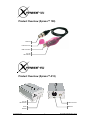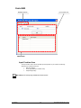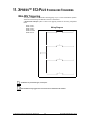
1
Software Version 6.22 beta1
Rev. 02f
User Manual
3000 N 29th Ct, Hollywood, FL 33020 U.S.A.
(800) 762-1084 – (954) 929-1115
FAX (954) 929-5560
www.chauvetlighting.com
TABLE OF CONTENTS
1. BEFORE YOU BEGIN ....................................................................................................................................................... 5 WHAT IS INCLUDED ............................................................................................................................................................ 5 UNPACKING INSTRUCTIONS ................................................................................................................................................ 5 MANUAL CONVENTIONS ..................................................................................................................................................... 5 ICONS ............................................................................................................................................................................... 5 2. INTRODUCTION ............................................................................................................................................................... 6 SOFTWARE FUNCTIONS ..................................................................................................................................................... 6 Control board ............................................................................................................................................................... 6 Setup ............................................................................................................................................................................ 6 Editor ............................................................................................................................................................................ 6 Live ............................................................................................................................................................................... 6 Stand alone .................................................................................................................................................................. 6 Backup/restore ............................................................................................................................................................. 6 3d view ......................................................................................................................................................................... 6 Timeline ........................................................................................................................................................................ 6 PRODUCT OVERVIEW (XPRESS™ 100) .............................................................................................................................. 7 PRODUCT OVERVIEW (XPRESS™-512) .............................................................................................................................. 7 PRODUCT OVERVIEW (XPRESS™-512 PLUS) ..................................................................................................................... 8 3. INTERFACES .................................................................................................................................................................... 9 FUNCTIONS ....................................................................................................................................................................... 9 Xpress 100 ................................................................................................................................................................... 9 Xpress 512 ................................................................................................................................................................... 9 Xpress 512-Plus ........................................................................................................................................................... 9 POWER CONNECTION ........................................................................................................................................................ 9 Xpress 100 ................................................................................................................................................................... 9 Xpress 512 ................................................................................................................................................................... 9 Xpress 512-Plus ........................................................................................................................................................... 9 4. SETTING UP THE HARDWARE/SOFTWARE ............................................................................................................... 10 MINIMUM HARDWARE REQUIREMENTS (WITHOUT 3D VISUALIZATION) ................................................................................ 10 MINIMUM HARDWARE REQUIREMENTS (WITH 3D VISUALIZATION) ....................................................................................... 10 SOFTWARE INSTALLATION (WINDOWS® XP, VISTA & 7) .................................................................................................... 10 HARDWARE DRIVER INSTALLATION (WINDOWS® VISTA & 7) .............................................................................................. 13 DRIVER INSTALLATION (WINDOWS® XP) .......................................................................................................................... 13 DRIVER INSTALLATION (MAC OSX) .................................................................................................................................. 15 DRIVER REINSTALLATION (WINDOWS® VISTA & 7) ............................................................................................................ 15 DRIVER REINSTALLATION (WINDOWS® XP) ...................................................................................................................... 15 INTERFACE TROUBLESHOOTING ....................................................................................................................................... 15 5. OVERVIEW...................................................................................................................................................................... 17 CONTROL BOARD ............................................................................................................................................................ 17 Notification Area ......................................................................................................................................................... 17 SETUP ............................................................................................................................................................................ 17 Personal Fixtures ....................................................................................................................................................... 17 Fixture 3D View Settings ............................................................................................................................................ 17 Fixture Channels ........................................................................................................................................................ 17 Channel Levels .......................................................................................................................................................... 17 Addressed Fixtures .................................................................................................................................................... 17 SETUP (CONTINUED) ........................................................................................................................................................ 18 EDITOR ........................................................................................................................................................................... 19 Pan/Tilt, RGB Area ..................................................................................................................................................... 19 Step Area ................................................................................................................................................................... 19 2D View ...................................................................................................................................................................... 19 Fixture Fader Area ..................................................................................................................................................... 19 LIVE-BUTTONS ................................................................................................................................................................ 20 Board Selection .......................................................................................................................................................... 20 Scene Area ................................................................................................................................................................ 20 Options Area .............................................................................................................................................................. 20 LIVE-TIMELINE ................................................................................................................................................................. 21 Show Control Section................................................................................................................................................. 21 Current Time Location................................................................................................................................................ 21 Zoom Control ............................................................................................................................................................. 21 Timelines .................................................................................................................................................................... 21 PATCH-DMX ................................................................................................................................................................... 22 2
Chauvet® ShowXpress™ V6.22
Input Creation Area .................................................................................................................................................... 22 PATCH-MIDI ................................................................................................................................................................... 23 6. PROGRAMMING ............................................................................................................................................................. 24 PROGRAMMING CONCEPT ................................................................................................................................................ 24 CREATING A FIXTURE PROFILE (EXAMPLE)........................................................................................................................ 24 3D View Area ............................................................................................................................................................. 25 DMX PATCHING .............................................................................................................................................................. 25 DIP switch Calculator ................................................................................................................................................. 26 DMX Addressing Setting ............................................................................................................................................ 26 CREATING A SCENE ......................................................................................................................................................... 27 2D VIEW ......................................................................................................................................................................... 28 Modifying the Layout ......................................................................................................................................................................................... 28 Modifying the Fixture Size(s) ............................................................................................................................................................................ 28 Modifying the Background ................................................................................................................................................................................ 28 Modifying the Fixture Image.............................................................................................................................................................................. 28 Hiding Fixtures .................................................................................................................................................................................................. 28 GENERATOR ................................................................................................................................................................... 29 Creating a Scene using Generator ................................................................................................................................................................... 30 Working with “Curves” ................................................................................................................................................................................... 32 Working with “Lines”...................................................................................................................................................................................... 32 Working with “Points” .................................................................................................................................................................................... 32 Fixture Groups (Editor Screen) .................................................................................................................................. 33 Selecting Fixtures from the Editor Screen ........................................................................................................................................................ 33 Selecting Fixtures by Groups ............................................................................................................................................................................ 33 Creating a Group............................................................................................................................................................................................... 33 7. PLAYBACK ..................................................................................................................................................................... 35 IMPORTING SCENES INTO THE LIVE-BUTTONS SCREEN ..................................................................................................... 35 SCENE PLAYBACK MODIFICATIONS................................................................................................................................... 36 Flash button ...................................................................................................................................................................................................... 36 Preset button ..................................................................................................................................................................................................... 36 No loop button ................................................................................................................................................................................................... 37 LIVE-BUTTONS PAGE PLAYBACK MODIFICATIONS ............................................................................................................. 37 Chase play ........................................................................................................................................................................................................ 37 Random play ..................................................................................................................................................................................................... 37 Solo play............................................................................................................................................................................................................ 37 LIVE-BUTTON SCREEN PLAYBACK .................................................................................................................................... 38 Play/Pause ........................................................................................................................................................................................................ 38 Speed Button .................................................................................................................................................................................................... 39 Sound Triggering (Auto BPM) ....................................................................................................................................................................... 40 Manual BPM.................................................................................................................................................................................................. 41 Manual Speed ............................................................................................................................................................................................... 41 Freeze ............................................................................................................................................................................................................... 42 Startup Properties ............................................................................................................................................................................................. 42 3D VIEW ......................................................................................................................................................................... 43 X and Y viewing angles..................................................................................................................................................................................... 43 Position of the view ........................................................................................................................................................................................... 43 Size of the stage ............................................................................................................................................................................................... 43 Operation........................................................................................................................................................................................................... 43 Stage Setting Sub-Screen.......................................................................................................................................... 44 Wall Textures .................................................................................................................................................................................................... 44 Fixture Settings Sub-screen ....................................................................................................................................... 45 LIVE-TIMELINE SCREEN ................................................................................................................................................... 46 Triggering a Timeline through the Live Screen................................................................................................................................................. 46 Adding Video/Picture Files to Live-Timeline ..................................................................................................................................................... 47 Screen Control Properties................................................................................................................................................................................. 47 Video output ...................................................................................................................................................................................................... 47 Output Size ....................................................................................................................................................................................................... 48 Adding Audio Files to Live-Timeline ................................................................................................................................................................. 48 Live-Timeline Overview .............................................................................................................................................. 49 Mouse Shortcuts in Live-Timeline ..................................................................................................................................................................... 49 Renaming the Rows .......................................................................................................................................................................................... 49 Creating a New Timeline................................................................................................................................................................................... 50 Using the “OFF” tool.......................................................................................................................................................................................... 50 Using the “STOP” tool ....................................................................................................................................................................................... 50 Operation for “Move To” in Live-Timeline ..................................................................................................................................................... 51 File Properties in Live-Timeline .................................................................................................................................................................... 51 8. UPLOAD SCREEN .......................................................................................................................................................... 52 UPLOADING SCENES TO THE INTERFACES ........................................................................................................................ 52 Xpress 512 ................................................................................................................................................................. 52 3
Chauvet® ShowXpress™ V6.22
Xpress 512-Plus ......................................................................................................................................................... 52 Update Internal Clock ....................................................................................................................................................................................... 52 9. BACKUP/RESTORE ....................................................................................................................................................... 54 EXPORT .......................................................................................................................................................................... 54 IMPORT ........................................................................................................................................................................... 54 10. KEYBOARD SHORTCUTS ........................................................................................................................................... 55 SETUP SCREEN ............................................................................................................................................................... 55 EDITOR SCREEN.............................................................................................................................................................. 55 LIVE-BUTTONS ................................................................................................................................................................ 55 LIVE-TIMELINE ................................................................................................................................................................. 55 2D VIEW ......................................................................................................................................................................... 55 SCREENCONTROL (VIDEO PLAYBACK WINDOW FROM THE LIVE SCREEN) ............................................................................ 55 11. XPRESS™ 512-PLUS STANDALONE TRIGGERING ................................................................................................. 56 MINI-DIN TRIGGERING..................................................................................................................................................... 56 IR (WIRELESS) TRIGGERING ............................................................................................................................................ 57 Proprietary CHAUVET® Remote ............................................................................................................................... 57 Operation........................................................................................................................................................................................................... 57 Generic Remote ......................................................................................................................................................... 57 12. UPDATING THE INTERFACE FIRMWARE ................................................................................................................. 58 13. APPENDIX..................................................................................................................................................................... 59 DMX PRIMER .................................................................................................................................................................. 59 DATA CABLING ................................................................................................................................................................ 59 DMX Data Cable ........................................................................................................................................................ 59 Cable Connectors ...................................................................................................................................................... 60 FIXTURE LINKING ............................................................................................................................................................. 60 3-Pin to 5-Pin Conversion Chart ................................................................................................................................ 61 Setting up a DMX Serial Data Link............................................................................................................................. 61 CONTACT US .................................................................................................................................................................. 61 RETURNS PROCEDURE .................................................................................................................................................... 62 CLAIMS ........................................................................................................................................................................... 62 GLOSSARY ...................................................................................................................................................................... 63 14. TECHNICAL SPECIFICATIONS ................................................................................................................................... 65 CHAUVET®, 2010, All Rights Reserved Information and specifications in this User Manual are subject to change without notice. CHAUVET® assumes no responsibility or liability for any errors or inaccuracies that may appear in this manual. 4
Chauvet® ShowXpress™ V6.22
1. BEFORE YOU BEGIN
What is included
Each ShowXpress™ interface ships with an 8 cm disk containing the software and hardware drivers.
•
•
•
1 x Interface
1 x ShowXpress™ Lighting Controller Software
1 x USB Cable
Unpacking Instructions
Immediately upon receiving a fixture, carefully unpack the carton, check the contents to ensure that
all parts are present, and have been received in good condition. Notify the shipper immediately and
retain packing material for inspection if any parts appear damaged from shipping or the carton itself
shows signs of mishandling. Save the carton and all packing materials. In the event that a fixture
must be returned to the factory, it is important that the fixture be returned in the original factory box
and packing.
Manual Conventions
CHAUVET® manuals use the following conventions to differentiate certain types of information from
the regular text.
MEANING
CONVENTION
[3D View]
<Menu>
1~512
50/60
Settings
MENU > Settings
ON
Personal Fixtures
A main screen accessed through the control board
A sub screen accessed through a main screen
A range of values
A set of values of which only one can be chosen
A menu option not to be modified (for example, showing the operating
mode/current status)
A sequence of menu options to be followed
A value to be entered or selected
A sub-section of a window
Icons
This manual uses the following icons to indicate information that requires special attention on the
part of the user.
MEANING
ICONS
This paragraph contains critical installation, configuration or operation
information. Failure to comply with this information may render the fixture
partially or completely inoperative, cause damage to the fixture or cause
harm to the user.
This paragraph contains important installation or configuration information.
Failure to comply with this information may prevent the fixture from
functioning correctly.
This paragraph reminds you of useful, although not critical, information.
1. BEFORE YOU BEGIN
5
Chauvet® ShowXpress™ V6.22
2. INTRODUCTION
Software Functions
Control board
•
Main window where all other screens are accessed
Setup
•
•
•
•
•
Create new fixture profiles or select from internal library
Automatically assign DMX addresses to list of fixtures
Assign fixture settings for 3D View
Define channel configurations and values
Import custom icons for use with gobo wheels
Editor
•
•
•
•
•
•
•
Easily program steps, scenes and shows
Up to 600 steps per scene
Access built-in macros (through the Generator)
On-screen color and gobo selections
On-screen 2D View
Stage re-sizing for multiple venues with the same scenes (generator only)
Unlimited scenes (when using a computer)
Live
•
•
•
•
•
Simultaneous playback of multiple lighting scenes (layering)
Completely user-configurable
Separate windows (boards) with unlimited pages per window
Trigger scenes by mouse click, keyboard, date and time, manual BPM (sound, MIDI and external
DMX signal triggering coming soon)
Playback timelines with lighting, audio and video with a single click
Stand alone
•
•
•
Select individual scenes to upload to the X-Factor™, Xpress Plus™, Xpress™ 512, or
Xpress™ 512-Plus interfaces
Stand-alone scenes automatically start when computer is removed or powered OFF
Simultaneous playback of multiple lighting scenes (layering) (with Xpress Plus™ & Xpress™ 512
Plus interface only)
Backup/restore
•
•
•
Import and export shows from others
Email backup files to friends or co-workers
Backup and restore an unlimited number of shows
3d view
•
•
•
•
See and control a complete show in real-time from any point of view
Create new 3D objects or select from internal library
Change object’s position, orientation, scale and color
Import custom images to use as the ceiling, floor or walls
Timeline
•
•
2. INTRODUCTION
Synchronize playback of the audio, video, and photographic files with the light show
Easy layout options with the visual drag-n-drop interface.
6
Chauvet® ShowXpress™ V6.22
Product Overview (Xpress™ 100)
DMX Out
Protective Cover
USB Connection
PC Link
LED Indicator
Product Overview (Xpress™-512)
PC Link
LED Indicator
USB Connection
DMX Out
Power
Indicator
2. INTRODUCTION
7
Chauvet® ShowXpress™ V6.22
Product Overview (Xpress™-512 Plus)
DMX Out
IR Receiver
External IR Receiver
IR Data
Indicator
Mini-DIN Scene Trigger
USB Connection
PC Link
LED Indicator
Security Location
Power
Indicator
Power: EXT/USB
External Power
2. INTRODUCTION
8
Chauvet® ShowXpress™ V6.22
3. INTERFACES
Functions
Xpress 100
•
•
•
•
USB to DMX cable
10 fixtures with a maximum of 100 DMX channels
Unlimited shows when using a computer
3D rendering available ONLY when interface is NOT connected
Xpress 512
•
•
•
•
DMX-512 USB interface
Connect multiple interfaces for more universes
Unlimited shows when using a computer
Playback 1 show without a computer
Xpress 512-Plus
•
•
•
•
•
•
•
•
•
•
DMX-512 USB interface
Connect multiple interfaces for more universes
Mini-DIN connector for external triggering
Infrared sensor for wireless scene triggering
Connection on rear for Infrared extension
Selectable power options: USB or AC/DC
Built-in electrical isolation for DMX line
Playback up to 18 shows without a computer (with speed control and layering)
Unlimited shows when using a computer
Internal calendar for date & time trigger without a computer
Power Connection
Xpress 100
This interface runs on USB bus power. During operation on a computer, it will receive its power from
the USB connection.
Xpress 512
This interface runs on USB bus power. During operation on a computer, it will receive its power from
the USB connection.
When operating this in standalone mode, it is necessary to use a USB power adapter to
provide power. This adapter output must not exceed 12 VDC, 300 mA. This power adapter is
sold separately.
Xpress 512-Plus
This interface runs on USB bus power. During operation on a computer, it will receive its power from
the USB connection.
When operating this in standalone mode, it is necessary to use a power supply to provide
power. This adapter output must not exceed 12 VDC, 300 mA. This power supply is sold
separately.
3. Interfaces
9
Chauvet® ShowXpress™ V6.22
4. SETTING UP THE HARDWARE/SOFTWARE
Minimum Hardware Requirements (without 3D
visualization)
•
•
•
•
•
•
Pentium 1Ghz with 512MB RAM under Windows® XP (32-bit only)
Pentium 2Ghz with 1GB RAM under Windows® Vista (32-bit only)
Pentium 2Ghz with 1GB RAM under Windows® 7 (32-bit & 64-bit)
100MB of hard disk space
1 CD-ROM drive (not necessary when acquiring via internet)
1 USB port
ShowXpress™ on a Windows 64-bit installation is compatible with ONLY the following
interfaces: Xpress™ 512, Xpress™ 512-Plus.
Minimum Hardware Requirements (with 3d
visualization)
•
•
•
•
All requirements above
ATI Radeon™ 7000 or NVIDIA® GeForce2 (gobo viewing disabled)
ATI Radeon™ 9000 or NVIDIA® GeForce4 (maximum 3D rendering)
Does not take into account multimedia operation on machine
Software Installation (Windows® XP, Vista & 7)
There are two options for obtaining the installation file. The file ships on the CD that arrives in the box
when purchasing an interface from Chauvet®. Or, the file may be downloaded from the internet. This
is recommended to be sure that you are using the latest version of the software.
The computer will display the interfaces with a different reference when installing the driver. Please
see the list below for these references. These names will only be displayed after the initial installation
on the computer.
•
Xpress™ 100: CABLE
•
XFACTOR™: BOX
•
Xpress™ Plus: PLUS
•
Xpress™ 512: D512
•
Xpress™ 512-Plus: REMOTE
Please go to the following web address to download the software:
http://www.chauvetlighting.com/showXpress-software/
1.
2.
4. Setup
Double-click the ShowXpress™ icon to initiate the software installation.
Click <NEXT> to continue.
10
Chauvet® ShowXpress™ V6.22
4. Setup
3.
4.
On the License Agreement page, select “I accept the agreement”.
Click <NEXT> to continue.
5.
6.
Choose the installation directory to install ShowXpress™. The default location is C:\Program
Files\ShowXpress and usually does not need to be altered.
Click <NEXT> to continue.
7.
8.
Select a name and location for Windows® to place the Start Menu folder.
Click <NEXT> to continue.
9.
Check the box titled “Create a desktop icon” if you want a folder to be created on your
desktop. This action cannot be undone so it may be better to create the folder and delete it later
if desired.
11
Chauvet® ShowXpress™ V6.22
10. Click <NEXT> to continue.
11. Confirm the settings and then click <INSTALL> to continue.
12. After the installation completes, click <FINISH> to confirm.
You must be logged in as Administrator to install the software.
4. Setup
12
Chauvet® ShowXpress™ V6.22
Hardware Driver Installation (Windows® Vista & 7)
After the software is installed, it is time to connect the interface to the computer. Make sure the
ShowXpress™ software is not running while attempting to connect the interface to the computer. To
connect the interface, please follow the instructions below:
These instructions do not account for the “User Account Control” security measure that Windows®
Vista has. Simply click <CONTINUE> if that window should appear during installation.
1.
2.
3.
Close all ShowXpress™ windows
Plug the USB cable into the back of the interface and the other end into an available USB port
on the computer.
A message will appear indicating that Windows® needs to install a driver. Click “Locate and
install driver software” and the computer will automatically search for the drivers that were
installed during the software installation.
This may take a few minutes to complete.
4.
A message indicating that the publisher cannot be verified may appear, simply click “Install this
driver software anyway” to continue with the installation.
5.
A message will appear indicating that the driver installation was successful and the “stand alone”
LED will turn off (X-Factor™) and “PC Link” will turn on (Xpress™ Plus, Xpress™ 512, Xpress™
512-Plus) indicating that a proper connection to the computer has been established.
Driver Installation (Windows® XP)
After the software is installed, it is time to connect the interface to the computer. Make sure the
ShowXpress™ software is not running while attempting to connect the interface to the computer. To
connect the interface, please follow the instructions below:
A driver must be installed for each interface connected to the computer.
1.
2.
4. Setup
Close all ShowXpress™ windows
Plug the USB cable into the back of the interface and the other end into an available USB port
on the computer. The “Found New Hardware Wizard” must be completed in order for the
computer to communicate with the interface.
13
Chauvet® ShowXpress™ V6.22
3.
4.
4. Setup
When Windows® XP asks if it can “connect to Windows® Update to search for software”
select “No, not this time”
Click <NEXT> to continue.
5.
On the next screen, select the bubble that reads “Install the software automatically
(recommended)”
6.
When the following window appears prompting that the driver did not pass the Windows® Logo
testing compatibility, simply click <CONTINUE ANYWAY> to continue the installation.
7.
When it’s complete, click <FINISH> and the window will disappear and a popup window will
indicate that the driver installation was successful.
14
Chauvet® ShowXpress™ V6.22
Driver Installation (Mac OSX)
It is not necessary to install the drivers when running the software within Mac OSX. The drivers will install
automatically after the software is installed successfully.
Driver Reinstallation (Windows® Vista & 7)
If the driver installation fails or you need to reinstall the driver for any reason, the driver can be installed
manually. Please follow the instructions below:
1.
2.
Click [START>CONTROL PANEL>SYSTEM>DEVICE MANAGER] to access the hardware devices
on your computer.
Extend the “Universal Serial Bus Controllers” section by clicking on the small square to the left.
3.
Highlight the “BOX Interface (version x.xx)” (or “USB Plus interface) and select “uninstall” on the top
menu bar. This will uninstall all associated drivers for the interface.
4.
Click “scan for hardware changes” also on the top menu bar to have the computer auto-detect any
new hard ware.
5.
The computer will automatically scan and install the necessary drivers for this device.
Driver Reinstallation (Windows® XP)
If the driver installation fails or you need to reinstall the driver for any reason, the driver can be installed
manually. Please follow the instructions below:
1.
2.
Click [START>CONTROL PANEL>SYSTEM >HARDWARE>DEVICE MANAGER] to access the
hardware devices on your computer.
Extend the “Universal Serial Bus Controllers” section by clicking on the small square to the left.
Interface Troubleshooting
If the driver installation is successful, the following results will occur.
4. Setup
1.
The LED indicators should read as follows:
•
Xpress™ 512:
“PC Link” LED Flashing
•
Xpress™ 512-Plus:
“PC Link” LED Flashing
•
XFACTOR:
“Stand-alone” LED OFF
•
Xpress™ Plus:
“PC Link” LED Flashing
•
Xpress™ 100:
“PC Link” LED Flashing
2.
The software will display the following upon starting up:
•
Interface found”
•
The appropriate interface name(s)
15
Chauvet® ShowXpress™ V6.22
4. Setup
3.
Highlight the “BOX Interface (version x.xx)” (or “USB Plus interface, CABLE, REMOTE, or D512) and
select “uninstall” on the top menu bar. This will uninstall all associated drivers for the interface.
4.
Click “scan for hardware changes” also on the top menu bar to have the computer auto-detect any
new hardware.
5.
6.
Repeat the same steps from “Hardware Installation (Windows® XP)” to install the driver again.
A popup balloon in the lower, right side of the monitor will indicate that the driver installation was
successful and the device is ready to use.
16
Chauvet® ShowXpress™ V6.22
5. OVERVIEW
Control Board
Notification Area
The Notification Area displays the following information:
•
•
•
Current Show (name)
Quantity of universes
Name(s) of interface(s) (if any)
Notification Area
DMX Levels
Settings
Import
Forum
Export
Manual
Setup
Patch
Editor
Upload
Live
3D View
Setup
Personal Fixtures
The Personal Fixtures displays the fixtures that have been loaded into the current show.
Adding fixtures to this area does not add them into the DMX patch. An extra step is needed to
complete that task.
Fixture 3D View Settings
The Fixture 3D View Settings displays the selected fixture’s current [3D View] attributes. This does
not affect the programming for the product connected. It does affect the appearance of the fixture in
the [3D View].
Fixture Channels
The Fixture Channels displays the selected fixture’s channels. When a fixture is selected, the
channels may be modified (cut, copy, paste, insert, and add).
Channel Levels
The Channel Levels displays the selected fixture’s channel levels. When a fixture is selected, the
channels may be modified (cut, insert, and add).
Addressed Fixtures
The Addressed Fixtures displays the current DMX patch. When a fixture is selected, they may be
modified (DMX address, name, reverse pan/tilt, universe)
5. Overview
17
Chauvet® ShowXpress™ V6.22
Setup (continued)
Toolbar Area:
New, Insert,
Save, Save as,
Delete
Universe Area:
Select the universe
to modify (up to 6)
Fixture 3D View
Settings
Personal Fixtures
Personal Fixtures
Fixture Channels
Channel Values
Addressed Fixtures
The Channel Values displays the selected fixture’s channel levels. When a channel is selected, the
levels may be modified (cut, insert, and add).
5. Overview
18
Chauvet® ShowXpress™ V6.22
Editor
Pan/Tilt, RGB Area
The Pan/Tilt, RGB Area modifies the following attributes:
•
•
Pan/Tilt location
Red, Green, and Blue using a color palette
Step Area
The Step Area accesses the following attributes:
•
•
•
•
Step: delete, copy, paste, insert, add
Step name
Step duration
Direct access to Step selection
2D View
The 2D View accesses the following functions:
•
•
Direct fixture selection in pictorial form
Selecting a fixture here also selects it in the Fixture Fader Area
Fixture Fader Area
The Fixture Fader Area accesses the following functions:
•
•
Direct Attribute manipulation in fader form
Group assignment and callback for more convenient programming
Generator
DMX On/Off
Undo, Redo
3D On/Off
Toolbar Area:
New, Insert,
Save, Save as
Pan/Tilt, RGB Area
5. Overview
2D View
Step Area
Play Scene
Channel Transition Area
19
Fixture Fader Area
Chauvet® ShowXpress™ V6.22
Live-Buttons
Board Selection
The Board Selection Bar modifies the following attributes:
•
•
•
Current page view
Add scenes to current page
Modify page options
Scene Area
The Scene Area accesses the following attributes:
•
•
•
Direct scene triggering
Scene playback speed
Trigger method modification
Options Area
The Options Area accesses the following controls:
•
•
•
•
•
•
Play/Pause button
Current BPM (also capable of manual input)
Tap Sync (press multiple times to modify current BPM
Freeze (freezes entire DMX output of the Live screen to the current step)
DMX On/Off (double as a blackout function)
3D View On/Off (enables playback in the 3D View screen)
Board Selection Bar
Options Area
Play/Pause
Current BPM
BPM Visual
Indicator
Tap Sync
Freeze
DMX On/Off
3D View
On/Off
Scene Area
5. Overview
20
Chauvet® ShowXpress™ V6.22
Live-Timeline
Show Control Section
Zoom Control
Current Time Location
Timelines
Show Control Section
The Show Control Section modifies the following attributes:
•
•
•
•
•
Go to beginning/start
Play from Red Marker
Play from current position
Stop
Go to End
Current Time Location
The Current Time Location displays the following attribute:
•
Current pause location, current progress through the show
Zoom Control
The Zoom Control modifies the following attribute:
•
Modify the resolution of the timeline. This is useful when precision is important
Timelines
The Timelines displays the following attributes:
•
•
•
•
5. Overview
Layout of each individual timeline, including the Video/Picture, Audio, and 2~10 LightScene
timelines
Location of STOP and OFF markers
Location of red marker
Location of green marker
21
Chauvet® ShowXpress™ V6.22
Patch-DMX
DMX/MIDI Selection
Input Creation Area
Current Inputs
Input Creation Area
The Input Creation Area is where new DMX input assignments may be created. The following
attributes may be altered in this area.
•
•
•
DMX input address
Priority type (DMX input, software, HTP)
Output assignment(s)
The DMX input is currently only available for the first universe.
5. Overview
22
Chauvet® ShowXpress™ V6.22
Patch-MIDI
DMX/MIDI Selection
Device Selection
Selected Device Live
Transmission
5. Overview
23
Chauvet® ShowXpress™ V6.22
6. PROGRAMMING
Programming Concept
There are 3 primary screens to program a show in ShowXpress™. These are the Setup, Editor, and
Live screens.
Setup (Patch): assign the DMX starting addresses of the fixtures to be programmed
Editor: program several scenes, and save them to the hard disk
Live-Buttons: import the scenes that were programmed in the Editor screen, and play
them back with the press of a single button
The EDITOR SCREEN takes priority over the LIVE SCREEN. If the LIVE SCREEN is controlling a DMX
channel, and a DMX channel is also being controlled in the EDITOR SCREEN, the channel will receive
priority from the EDITOR SCREEN. (Only active channels in the EDITOR SCREEN will be affected.)
Overlaying is possible between the 2 screens (Editor and Live).
Creating a Fixture Profile (example)
ShowXpress™ is designed with the capability to create fixture profiles directly through the software.
This profile is going to be created for the Chauvet® LED PAR 64-Tri. This fixture has two operating
modes. We will be using the 3-channel operating mode.
The fixture has the following channels: red, green, and blue. Please see the steps below for an
example in designing a fixture profile.
1.
2.
3.
4.
5.
6.
7.
8.
9.
10.
11.
12.
13.
6. Programming
Press <New Fixture>.
In the screen that appears, enter a name for the fixture profile: LED PAR 64-Tri. Press
<OK>. The name should now appear in Personal Fixtures.
In the Channels Area, press <add channel> three times. Three channels should now
appear with the name: ???.
st
Right click on the 1 channel and left-click <EDIT>. The Set channel infos sub-window
should now appear.
Locate “red”, left-click on the word, and then press <ok>. The sub-window will automatically
st
close, and in the Channels Area, the 1 channel name and icon will now be changed to the
selection.
Follow the same steps as above to set channel 2 and 3 to green and blue, respectively.
Left-click channel 1.
In the Levels Area, Press <add level>.
Left click on the new level that appears.
Right-click this level and left-click “Edit”. A sub-window will appear titled Set level infos.
Left-click dimmer and set the max value to 255.
Press <ok>.
Follow this same procedure for channels two and three.
24
Chauvet® ShowXpress™ V6.22
3D View Area
To set the parameters of the 3D View for this fixture (LED PAR 64-Tri), see the following instructions.
1. In the drop down bar, select this fixture as a color changer.
2. Drag the lamp selection to 60W led.
The brighter the LED wattage is here, the brighter the fixture will appear in the 3D_View Screen.
3.
4.
Adjust the beam angle to 22°, to match the fixture (see the fixture specifications).
This fixture is now complete. Save the fixture.
Fixture Type
Lamp Selection Bar
Pan Maximum Angle
Reverse Pan
Tilt Maximum Angle
Reverse Tilt
Beam Angle
Reverse Dimmer
Reverse Iris
DMX Patching
In order to view a fixture in the Editor screen, you must first add it to the DMX Patch in the Setup
screen. Please see the instructions below to add the LED PAR 64-Tri to the DMX Patch.
1.
Switch the page tab in the Setup screen from fixtures setting to dmx addressing.
2.
Right-click on the LED PAR 64-Tri to highlight it and bring up the option “Add fixture to the
dmx list”. Click on this option.
The “DMX addressing setting” sub-menu will appear. Let’s start this fixture off at DMX
address 001. We will set the clone to 4. This will also be on universe 1. It is also necessary
to set a name for this fixture. Using this name, we may recognize the fixture easily in the
Editor screen during programming.
Press <Save>. The fixture is now added to the DMX Patch.
Repeat this process to add more fixtures.
3.
4.
5.
If there is a fixture that is not already in the “fixtures setting” page tab, then you may add more by using
the “import fixture” function.
6. Programming
25
Chauvet® ShowXpress™ V6.22
DIP switch Calculator
If using a fixture that uses DIP switches to assign the DMX address, ShowXpress™ will automatically
provide the DIP switches that must be used to achieve a given address. For Example, if you type an
address of 100 into the Setup screen for a fixture’s DMX address, the software will display an image
showing the following:
This shows that DIP switches
3, 6, and 7 must be turned to
the ON position to achieve an
address of 100.
DMX Addressing Setting
DMX Address
DIP Switch Calculator
Fixture Name
3D Fixture Clone
Reverse Pan
Reverse Tilt
6. Programming
26
Chauvet® ShowXpress™ V6.22
Creating a Scene
In ShowXpress™, a Scene consists of one or more steps. These steps are created in the Editor
screen.
In order to create scenes, please see the example below for using the LED PAR 64-Tri. This will be a
3-step color fading program from red, to green, and then blue. It will be 9 seconds total scene time.
1.
2.
Open the Editor screen from the Control Board.
Turn ON the DMX button by pressing it.
Red = OFF
Green = ON
3.
Create a look with the fixtures by using the faders in the
fader area. For this example, bring the red channel to
full output [255].
Change the transition type below the red fader to
“smooth”. This is done by clicking it with the mouse.
Adjust the name and time in the Step Area.
Add a new step by selecting the appropriate button in
the Step Area.
Bring the red fader channel down to [000].
Bring the green fader channel to full [255].
Change the transition type below the green to “smooth”.
Adjust the name and time in the Step Area.
Add a new step by selecting the appropriate button in
the Step Area.
Bring the green channel down to [000].
Bring the blue channel to full [255].
Change the transition type below the green to “smooth”.
Adjust the name and time in the Step Area.
Press “Play” to preview the scene.
Save the Light Scene as “RGB Color Fade”.
4.
5.
6.
7.
8.
9.
10.
11.
12.
13.
14.
15.
16.
17.
You may use the RGB Area to select your color.
Step Area
Add Step
button
Fixture Faders Area
Transition
Type
It may be easiest to program if the fixtures are connected and
operating in real time to the Editor screen.
Fast
Smooth
It is also possible to program using the 3D View screen. Turn on the
Transition
Transition
3D View button for this operation. This may be useful for creating
scenes while the Live screen is playing back other scenes. This is referred to as “Blind Programming”.
6. Programming
27
Chauvet® ShowXpress™ V6.22
2D View
The 2D View is integrated into the Editor screen. It is meant to be used as a tool to increase the
speed of programming by providing a visual fixture layout & selection palette.
The layout, size of fixtures, background, and fixture images are all attributes that may be quickly and
easily modified within the 2D View.
Modifying the Layout
When a fixture is added into the DMX patch in the Editor screen, it will appear in the 2D View.
There are default images that are used for these fixtures. Please follow the instructions below for
this operation.
1.
2.
3.
Left-click a fixture with the mouse.
While still holding the mouse button, drag the fixture to the desired location.
Release the mouse button.
The 2D View will NOT show any “cloned” fixtures. These will only appear in the 3D View screen.
Modifying the Fixture Size(s)
When multiple fixtures are added to the DMX patch, it may be difficult to work with them in full
size in the payout. It is possible to minimize their sizes to ½ or ⅓. This is a setting which affects
all of the fixtures in the 2D View. Please follow the instructions below for this operation.
1.
2.
3.
Right-click any location in the 2D View.
In the drop-down menu that appears, move the mouse pointer over “Images size”.
In the additional drop-down menu that appears after holding the mouse pointer over
“Images size”. There are 3 options. Select the desired option and the change is
complete.
Modifying the Background
The background of the 2D View may be modified to any custom JPG, BMP, or PNG image. The
user may wish to take a digital photo of the stage, and then move the fixture images to overlay the
correct location. With this option, available, it is a very fast process. Please follow the instructions
below for this operation.
1.
2.
3.
4.
Right-click any location in the 2D View.
In the drop-down menu that appears, move the mouse pointer over “Change
background”.
Left-click this option.
A file browser window will open. Use this to navigate to and select the desired image.
There is an option available in the 3D View to use the screenshot from that screen and set it to the 2D
View background.
Modifying the Fixture Image
The fixtures are set to a default image. However, they may be changed to a different image to
represent the fixture in the 2D View. Please follow the instructions below for this operation.
1.
2.
3.
Right-click the desired fixture in the 2D View. In the drop-down menu that appears, the
fixture name will appear for confirmation.
Left-click “Change Fixture Image”.
A file browser window will open. Use this to navigate to and select the desired image.
The format for the images must meet the following parameters: PNG file 128*128 pixels with alphachannel transparent background.
Hiding Fixtures
In the 2D_View section of the Editor Screen, it is possible to hide select fixtures. This is useful
when wanting to turn select fixture images ON/OFF.
7. Playback
28
Chauvet® ShowXpress™ V6.22
Generator
The Generator Screen is accessed within the Editor Screen. It can only be used while in the Editor
Screen.
It is recommended to read the section on “Working with Groups” before proceeding. Many of the
steps below assume that the user is familiar with groups and selecting with 2D View.
Once a generator scene has been created, it may be saved for later access and editing.
Toolbar Area
Fixture Attribute Area: this
area is where the fixture
attributes are
activated/deactivated in the
current generator scene
Edit Area: this area contains
the controls for the dimming
curves and fan effect attributes
Toolbar Area
”
Delete Current Scene
Save Scene
Create New Project
Generate Scene into the Editor Screen
DMX ON/OFF button
Pause Current Scene
Open Saved Project
3D_View Playback ON/OFF
Save Project As…
Stop Current Scene
Play Current Scene
7. Playback
29
Chauvet® ShowXpress™ V6.22
Creating a Scene using Generator
Follow the steps below to learn how to create a basic scene using the Generator Screen.
1.
2.
Open the Editor Screen from the Control Board.
Select one or more fixtures.
Once a generator scene has been created, it may be saved for later access and editing.
3.
Open the Generator Screen.
4.
The fixture attributes of the selected fixture(s) will appear in the “Fixture Attribute Area”.
Select the first attribute to be modified in the current scene. This is done by checking the
box next to the attribute name. This does not need to be done in order.
Progress bar
Check the box next to
the attribute to select it
5.
When you select an attribute, the “Edit Area” will modify the attribute for that particular
attribute, aside from the other attributes in the fixture.
•
There are preset “dimming curves” available. A user may also create custom
dimming curves and save them to the computer.
•
The total duration may be modified, in seconds.
•
There are 3 types of “transitions”: points, lines, curves
Shows the name of the
current loaded curve (if any)
“New Curve”, “Load Curve”,
“Save Curve”, “Delete Curve”
7. Playback
30
Chauvet® ShowXpress™ V6.22
7.
If there is more than one fixture selected, the delay time between the fixtures may be
altered by using the shift bar. Center on this bar is the same timing (value of “0”).
Negative or positive values determine which fixture is first in the generated scene.
8. Assign duration to the attribute.
9. Move onto the next attribute, and follow the same steps as above.
10. It is now time to save the generator scene. This is necessary in order to allow the scene
to be modified in the generator screen. If this generator scene is not saved, then it may
only be modified by directly modifying the time and fader values in the Editor screen.
11. After the generator scene has been modified and saved (if desired) as desired by the
user, it is necessary to “generate” the scene into the Editor Screen before being able to
use it in the Live Screen for playback. This is done by using the “generate” button,
located in the
12. Upon generating the scene in the above step, the scene will transport into the Editor
Screen, showing each individual step that has been created in the generator screen.
Further editing is possible here, but is not necessary.
The Pan/Tilt attributes for any fixture will appear as a single attribute in the “Fixture Attribute
Area”. The waveform for pan/tilt will be an oval and will modify both pan and tilt attribute
together, as though they were coordinates on a map.
If you want a single channel to remain at a constant level, with no variations (such as the
dimmer channel), then simply select the dimmer channel, and leave both of the 2 points at the
same level. Do NOT add a third point. See below for example.
7. Playback
31
Chauvet® ShowXpress™ V6.22
Working with “Curves”
When working with a fixture attribute, there is a graphical representation of the dimming curve
that may be altered. Use the mouse to modify the curve.
Time
End time
100%
Start time
0%
100%
(DMX value of 255)
Dimming
Points
0%
(DMX value of 000)
Working with “Lines”
The waveform will be gradual, and appear as below.
Working with “Points”
The waveform will be square, and appear as below.
7. Playback
32
Chauvet® ShowXpress™ V6.22
Fixture Groups (Editor Screen)
The Editor Screen contains 512 channels of control, and all of them are laid out in fader format
along the bottom of the screen. A scroll bar is provided to navigate manually. However, there is a
much better tool that is provided to move through the Editor screen quickly. This is called Groups.
Groups allow the user to jump from one fixture to another with a single keystroke. This is crucial
when working with multiple fixtures. Please see the instructions below for further description on
how to create and work with groups.
It is also possible to select fixtures in the 2D_View area of the Editor Screen.
Selecting Fixtures from the Editor Screen
•
•
•
•
2 or more fixtures must be selected in order to enable access to the Generator Screen.
Fixtures may be selected in the 2D_View section of the Editor Screen.
It is possible to select multiple fixtures by holding down the CTRL/APPLE key.
Groups may be used to select a fixture.
Selecting Fixtures by Groups
When a group has been created, simply press the shortcut key to highlight/select it. This
will only work in the Editor Screen.
Creating a Group
This is done in the Editor Screen. Please follow the steps below for this operation.
1.
2.
Open the Editor Screen from the Control Board.
Scroll to a fixture’s title bar. Using the left mouse button, double-click on the title bar.
It will highlight in red color to signify that it has been selected.
3.
Continue to highlight more fixtures in the same fashion as above. Hold down the
CTRL/APPLE key on the keyboard to allow you to select multiple fixtures.
Then, press the Groups tab.
4.
7. Playback
33
Chauvet® ShowXpress™ V6.22
5.
On the right-hand section of the screen, right click in the group area to bring up the
menu. Select “Add new group”.
6.
A sub-window will appear. Type a name for the group here.
7.
8.
Press OK.
Another sub-window will appear. Type in a single character and this is the group
selection shortcut.
The available keyboard shortcuts are: a~z, A~Z. It is possible to make 52 total groups.
7. Playback
34
Chauvet® ShowXpress™ V6.22
7. PLAYBACK
Importing Scenes into the Live-Buttons Screen
In ShowXpress™, playback is intended to occur in the Live screen. Initially, the Live screen does not
include any scenes. It is a clear palette, which allows the user to arrange the screen according to the
needs of their show.
Several parameters may be customized in the Live-Buttons screen, including, but not limited, to the
following: page-name, order, quantity, chase-play, random-play, solo-play, and scene order, quantity,
color, type, trigger method, speed-override.
In order to import scenes into the Live-Buttons screen, please follow the steps below. We will be
importing the 3-step color fading that we created in the Editor section on “Creating a Scene”.
1.
2.
3.
4.
5.
6.
7.
8.
Open the Live screen from the
Control Board.
Right-click the Board Selection
Bar and select Add Light Scene.
See fig. L.a.
Select “RGB Color Fade” from
the file explorer window that
appears and press <Open>.
The Scene will now appear in
the Live screen as a single
button, completely filling up the
empty space. See fig. L.c.
Right-click on the Scene button
and select “Trigger button”. The
Trigger button sub-menu will
open. See fig. L.b.
Check the box next to Keyboard
Trigger.
Using the drop-down menu,
select <a> as the keyboard
trigger.
Close the window to save.
Live screen
Add Light
Scene button
fig. L.a
Drop-down
menu
Keyboard
checkbox
If you do not see the keyboard trigger
on the Scene button in the Live screen,
then you need to enable this from the
“Display” option located directly
underneath the window title bar.
If you need to trigger this scene using
the computer’s calendar, then you may
select the apprpriate settings in the
Trigger button sub-menu.
fig. L.b
(Scene added and trigger set to <a>)
Multiple scene may be selected and
imported simultaneously, provided
that they atre located in the same
folder.
Scene
Name
Keyboard
Trigger
fig. L.c
7. Playback
35
Chauvet® ShowXpress™ V6.22
Scene Playback Modifications
Flash button
In the Live-Buttons screen, it may be necessary to require fast, momentary, playback of a
scene. Fog machines & strobe lights are examples of such requirements.
While there are several methods to accomplish this task, one such method to accomplish this
is by using the Flash feature. Please see the steps below which show how to modify a scene
to operate with this function.
1.
2.
3.
4.
Create a scene to use in
the Editor scene.
Add the scene to the Live
screen.
Right-click on the Scene
button, and select “Flash
button”. See fig. F.a.
Set a keyboard shortcut
for this Scene button as
<b>.
In the above scenario, whenever
<b> is pressed, the scene will be
triggered. And, this scene will run
for as long as this key is held
down. The moment that this key is
released, the scene will stop
playing. This is “momentary”.
Flash button
Flash button
fig. F.a
Preset button
Preset button
With this feature, you may take a
scene that has multiple steps and
play only a single step back. This
is done by using the right-click
menu for “step” that appears after
enabling this function on a scene.
Preset
button
For the following example, we will
be using the scene that was
created in the Editor example:
“Creating a Scene”. Please see
the steps below for this procedure.
1.
2.
3.
4.
fig. T.a
Add the Scene “RGB Color Fade” into the Live-Buttons screen.
Right-click on the scene button and select “Preset button”. See fig. T.a.
You may now right-click, and scroll to a specific step in the scene to recall it. The
individual step name will appear, as created in the Editor Screen. Only the selected
step will play.
Trigger the button now in the desired method (keyboard, time, and/or mouse).
These 2 features (Preset button and Flash button) may be combined.
7. Playback
36
Chauvet® ShowXpress™ V6.22
No loop button
In the Live-Buttons screen, when a scene with a single step is triggered, it will remain ON as a
static look. However, when a scene with 2 or more steps is triggered, it will loop endlessly,
according to the time programmed in the Editor Screen.
st
There is a playback modification that will prevent a scene from looping after the 1 time
playing through all the steps in a scene. This is the “No loop button”. Please see the steps
below to enable this modification.
1.
2.
3.
4.
Add the Scene “RGB Color
Fade” into the Live screen.
Right-click on the scene button
and select “No loop button”.
The menu will now look as in
fig. Nl.a after another right-click
on the scene.
You may select a scene from
this menu before or after
activating/triggering. But, NO
LOOP must be selected first,
before this option will appear in
the right-click menu.
After selecting a scene from
this menu, you may trigger the
scene as normally as any other
scene.
No loop button
No loop
button
fig. Nl.a
Live-Buttons Page Playback Modifications
Chase play
In the Live-Buttons screen, there are page playback modifications that are unique for each page.
Chase play is one of these modifications. There are many purposes for this feature. For this
example, we will look at changing the colors. Please see the steps below for this feature.
1.
2.
3.
4.
5.
6.
7.
Using the Editor screen, create a scene for the LED PAR 64-Tri that has the following
parameters:
a. 3 second time
b. Smooth transition
c. 1 step
Using the Editor screen, create 2 more scenes with the above parameters, but use green for
one, and then blue for the other.
Using the Live screen, right-click on the Board Selection Bar to add a new page.
Title the new page as “Colors”. Press <Save>.
Add the 3 scene that were created in the steps above into this new page called “Colors”.
Right-click on the Board Selection Bar and select “Chase play”.
Trigger a scene.
After triggering a scene (it does not matter which scene is triggered), it will play through the
total time. If this time has been set correctly (3 sec), then after 3 seconds, the next scene will
play. This will continue in sequential order, according to how the scenes have been arranged
on the page.
Random play
This function works identically as Chase play. The only difference is the order they play back.
Random play is not sequential. It is random in the order of the scene playback.
This only works on a single page in the Live-Buttons Screen.
Select multiple scenes before activating this function to play back multiple scenes at the same
time, randomly.
Solo play
Normally with the Live-Buttons screen, stacking scenes is standard. However, using this function,
nd
st
each page may only play one scene at a time. Triggering a 2 will disable the 1 .
This only works on a single page in the Live-Buttons Screen.
7. Playback
37
Chauvet® ShowXpress™ V6.22
Live-Button screen Playback
Play/Pause
This feature increases the functionality of the Live-Buttons screen by adding the following
possibilities: seamless playback, and multiple scene triggering simultaneously.
When using this function on a scene that is currently running, it will turn it off. When using this
function on a scene that is not currently running, it will turn it on.
This function is a 2-step process. The first step prepares the execution, and the second step
completes the execution. Please follow the steps below for this procedure.
1.
2.
3.
Press <Play/Pause>. See fig.
Pp.a.
Select a scene. The symbol will
appear on the scene button. This
is the preparation. See fig. Pp.b.
Press <Play/Pause> a second
time. This is the execution.
Play/Pause
This function may be used on an
unlimited quantity of scenes
Play/Pause
button
fig. Pp.a
Preparation
Prepared
button
7. Playback
38
fig. Pp.b
Chauvet® ShowXpress™ V6.22
Speed Button
The buttons in Live-buttons may function on different speeds. Auto BPM, Manual BPM, and
Manual Speed.
To access the Speed button window, follow the steps below.
1. Open Live-buttons from the Control Board.
2. Right-click on any light scene. A sub-menu will appear.
3. Select Speed button.
7. Playback
39
Chauvet® ShowXpress™ V6.22
Sound Triggering (Auto BPM)
When a light scene is operating in this mode, it will use the internal computer mixer to
determine the sound source.
Please see the steps below to access this setting (Windows® ONLY!).
1.
2.
3.
4.
5.
6.
7.
8.
9.
10.
11.
12.
13.
14.
Open the Windows® Control Panel.
If the view is not already set to “Classic View”, change it to this.
Open “Sounds and Audio Devices”.
Select the volume tab.
In the “Device volume” area, select the “Advanced” button. A new window will
open, displaying the playback mixer.
In the “Options” menu, select “Properties”.
In the new window that appears, refer to the “Adjust volume for” area. Select
“Recording”.
Refer to the volume controls at the bottom of the window, and place a check
mark next to the audio input you wish to trigger from in Live-buttons.
Press <OK>.
In the “Master Volume” window that appears, adjust the properties for the volume
input. Deselect the mute option; adjust the balance and volume settings.
Open Live-buttons from the Control Board.
Right-click on the scene button and select “Speed button”.
In the window that appears, select “auto BPM”.
Press <Validate>.
15. On the right-side of Live-buttons, turn the Auto BPM function ON by selecting
the check box.
16. If the source is sending signal at sound levels, then the indicator window should
appear as the image below demonstrates.
The purpose of this function is to synchronize the changing of the steps to the music.
The sensitivity may be adjusted between 1/1 and 1/8.
7. Playback
40
Chauvet® ShowXpress™ V6.22
Manual BPM
This is used for the playback speed of the scenes to synchronize with the audio BPM.
Please see the steps below to access this setting.
1.
2.
3.
4.
Open Live-buttons from the Control Board.
Right-click on the scene button and select “Speed button”.
In the window that appears, select “Manual BPM”.
Press <Validate>.
5.
See the diagram below for instructions on assigning the value for the Manual
BPM..
Manual Setting
(using numbers on keyboard)
Visual Indicator
Manual Setting
(Press 3 times)
This is a MANUAL setting, which will NOT synchronize with an external source.
BPM effects the time to switch to the next step in a scene
Available BPM: 10~500
Manual Speed
This mode refers to the manual adjustment in the speed of a program. This may be set
between 25% and 400%.
Please see the steps below to access this setting.
6.
7.
8.
9.
10.
7. Playback
Open Live-buttons from the Control Board.
Right-click on the scene button and select “Speed button”.
In the window that appears, select “Manual Speed”.
Using the slide-bar, press & hold to drag to the desired speed value.
Press <Validate>.
41
Chauvet® ShowXpress™ V6.22
Freeze
The freeze function will pause every activated scene from continuing to the next available step. All
scenes are held at the current step.
•
•
Press once to activate.
Press a second time to deactivate.
Startup Properties
There are five different options available that may be set when starting up the Live-Buttons
screen.
These settings are saved, even after closing the program, for future use.
Live screen is
maximized at startup
The normal window resizing
options are removed,
including the main, top bar
Automatically turn the DMX ON
when opening the Live Screen
Disable right-click options
within the Live Screen
Password-protect the
Options sub-window in
Live Screen
7. Playback
42
Chauvet® ShowXpress™ V6.22
3D View
X and Y viewing angles
This may be modified. To adjust this, please see the following steps.
1. Left-click any open space in the 3D View screen.
2. While holding the mouse button, drag the mouse in the desired direction to adjust the viewing
angle.
Position of the view
This may be adjusted by using a combination of the mouse and the keyboard. To adjust this,
please see the following steps.
1. Press and hold <SHIFT> on the keyboard.
2. Left-click any open space in the 3D View screen.
3. While holding the mouse button, drag the mouse in the desired direction to adjust the viewing
position.
Size of the stage
This may be adjusted within the 3D View screen. This is the “zoom”. To adjust this, please see
the following steps.
1. Left-click any open space in the 3D View screen.
2. While holding <SHIFT>, use the wheel on the mouse in the desired direction to adjust the
viewing position.
Operation
The 3D View is designed to be used along with either of the two screens: Editor or Live. In order
to activate the playback for the 3D view, there is a button in both of these screens. It must be
activated, with the button indicator showing green in order to have any playback in this screen.
7. Playback
43
Chauvet® ShowXpress™ V6.22
Stage Setting Sub-Screen
The 3D View has parameters to alter the stage. The stage is defined as the 6 walls in the 3D View.
The parameters that may be altered include the following: width, height, depth, texture, resolution of
the textures.
Wall Textures
The 3D View installs with several custom textures to choose from. These are accessible by using
the drop-down menu in the texture area. After selecting a texture and turning the texture ON, the
3D View screen will immediately display the texture on the applicable wall.
Custom textures must adhere to the following parameters in the file formatting: PNG, BMP,
and JPG.
Stage Settings
Total stage
size
Ambient
Lighting Level
Texture
resolution
Texture
ON/OFF
7. Playback
44
Chauvet® ShowXpress™ V6.22
Fixture Settings Sub-screen
The following parameters are available for fixture modification within the 3D View Screen: Position,
Orientation, Scale, and Color. Please see the steps below for accessing these settings.
4.
5.
6.
7.
8.
Open the 3D View
Right-click anywhere within the 3D View to bring up the menu.
Select “Fixtures settings”.
The window will open.
Select a fixture form the “Fixture Selection Area”. It will be highlighted in the 3D View
Screen so that it is possible to see the results of any change in settings immediately.
9. Select an attribute to modify from the Attribute Selection Area.
10. Use the “Value Setting Area” to adjust the setting(s). This may be done by entering the
value in directly with the keyboard or by using the mouse to manipulate the scroll tool.
Scroll tool
Enter Values
Directly
Attribute
Selection
Area
Fixture
selection area
Value
Setting
Area
Undo
button
7. Playback
45
Chauvet® ShowXpress™ V6.22
Live-Timeline Screen
Triggering a Timeline through the Live Screen
This feature allows the ability to save multiple timelines and trigger them through buttons in
the Live Screen.
1.
2.
Using the mouse, right-click the Board Selection Bar in the Live Screen to
bring up the sub-menu.
Select “Add timeline” with the left mouse button.
3.
A sub-window will appear. Use this window to select the appropriate
timeline.
4.
Select “Open”.
The right-click sub-menu options for Timeline buttons are limited in the Live Screen.
Timeline buttons in the Live Screen will appear with a unique background, as displayed below.
Timeline Title location
Background
7. Playback
46
Chauvet® ShowXpress™ V6.22
Adding Video/Picture Files to Live-Timeline
Live-Timeline may be used to trigger playback of video and/or picture files. This is useful
when synchronizing to the light show.
•
The following file formats are supported for video files:
avi, mpg, mpeg, mov, wmv
•
The following formats are supported for picture files:
bmp, gif, jpg, png
1.
2.
3.
Right-click in the files area in the Live-Timeline Screen to bring up the sunmenu.
Left-click “Add multimedia file”.
A sub-window will appear. Use this window to select the appropriate
video/picture file.
4.
Press “Open” to add the file to the timeline.
Screen Control Properties
Screen Control is the sub-window that is used for video and photo playback.
Output size
Miscellaneous
Video output
Video output
This section provides options on where to display the video, as well as the video location. You may
also choose between a windowed mode or a full screen mode.
No border: removes the window border and title bar
Always on top: forces the ScreenControl
window to remain on top of all other windows
Force Position: Disables the manual window
positioning and assigns a default X and Y position
Screen Mode: Select which display to appear on
(this is a full screen mode)
7. Playback
47
Chauvet® ShowXpress™ V6.22
Output Size
This section provides options on how to display the video window, as well as the video size.
No border: removes the window border and title bar
Always on top: forces the ScreenControl window
to remain on top of all other windows
Force Position: Disables the manual window
positioning and assigns a default X and Y position
Screen Mode: Select which display to appear on
(this is a full screen mode)
Adding Audio Files to Live-Timeline
Live-Timeline may be used to trigger playback of audio files. This is useful when
synchronizing to the light show.
•
The following file formats are supported for audio files:
Wav, mp3, ogg, wma
1.
7. Playback
2.
5.
Right-click in the files area in the Live-Timeline Screen to bring up the sunmenu.
Left-click “Add multimedia file”.
A sub-window will appear. Use this window to select the appropriate audio
file.
6.
Press “Open” to add the file to the timeline.
48
Chauvet® ShowXpress™ V6.22
Live-Timeline Overview
Timeline Name
Current
Progress
Texture
resolution
Rows
Zoom
(100%~1%)
Mouse Shortcuts in Live-Timeline
There are shortcuts available in the Live-Timeline screen, which may assist in arranging the
show.
Mouse functions:
1. Double click the “Time Ruler” to relocate the red marker.
2. Press the scroll wheel to scroll left to right (beginning to end).
Renaming the Rows
The rows in Live-Timeline may be modified to display custom titles. Please see the steps below
for further details. The following steps assume the Live-Timeline screen is already open and
operating.
1.
2.
3.
4.
Move the mouse over any of the timelines. This includes Video/Picture, Audio, and
LightScene rows.
Right-click to bring up the sub-menu.
This will cause the sub-window “Timeline name” to open. Enter a new name, using the
keyboard.
Press OK to complete the process.
7. Playback
49
Chauvet® ShowXpress™ V6.22
Creating a New Timeline
This feature is accessed through the Live-Timeline Screen. There is a second tab that
reveals this screen.
Please see the steps below for further details on this process.
1.
In the Live Screen title bar, select the Timeline drop-down menu and New.
2.
A sub-window will appear, where the basic parameters for the new timeline to
follow, such as total time and total quantity of LightScene rows. Make the necessary
adjustments and press OK.
Up to 10 LightScene rows may be added to a single timeline.
3.
The new timeline appears with nothing added to it. Add all of the files that are to be
added to the timeline, one at a time. See section on Adding files to timeline in the
previous sections.
Using the “OFF” tool
In the timeline, it is possible to stop a LightScene or multimedia file, on an individual row,
before it has completed. For this step, use the “OFF” tool.
1.
Right-click on the row to which you want to add the “OFF” tool. A sub-menu will
appear.
2.
Select “Add OFF tool”.
3.
After the tool has been added, it may be repositioned by left-clicking, holding, and
dragging with the mouse. Then, remove the mouse button to release the tool.
OFF tool
This will stop a single row.
Using the “STOP” tool
In the timeline, the show will play continuously. To define a stop position for all rows, a tool is
provided, called the “STOP” tool. This is added in the current timeline. For this step, use the
“STOP” tool.
1.
Right-click on the row to which you want to add the “STOP” tool. A sub-menu will
appear.
2.
Select “Add STOP tool”.
3.
After the tool has been added, it may be repositioned by left-clicking, holding, and
dragging with the mouse. Then, remove the mouse button to release the tool.
STOP tool
This will stop all rows.
7. Playback
50
Chauvet® ShowXpress™ V6.22
Operation for “Move To” in Live-Timeline
In Live-Timeline, dragging and dropping the files in position may not provide adequate
precision. For this reason, an option is available called “move to”.
This allows any object, including the OFF and STOP tools, to be moved to one of the
following positions:
Red marker
Green marker
Specific time
File Properties in Live-Timeline
Please see the options that are available for each different type of file in timeline.
Video/Picture Timeline
Turn off sound
playback for the file
(disables volume control)
Press to close
window and
save setting(s)
Continuous Loop
(excluding STOP tool)
Audio Timeline
Option not available
for Audio Timeline
Press to close
window and
save setting(s)
Continuous Loop
(excluding STOP tool)
LightScene Timeline
Auto beats per minute
(unchanged)
Adjust the playback speed
(manual speed ONLY!)
Manual beats per minute
(using Live Screen BPM global setting)
Manual Speed
(using the playback fader to the right)
Press to close
window and
save setting(s)
Continuous Loop
(excluding STOP tool)
(activated by default)
7. Playback
51
Chauvet® ShowXpress™ V6.22
8. UPLOAD SCREEN
Uploading Scenes to the Interfaces
Some, not all, of the ShowXpress™ interfaces have on-board memory and processing. This means
that they are capable of running one or more programs in standalone mode.
This feature may be useful for an automatic backup. Or, if there is not going to be a computer
available to operate the lighting, but a custom program is desired to be programmed in an easy to
learn interface, then this is a very useful option.
The instructions for uploading are going to vary between the different interfaces. Please see the
instructions for the interfaces.
Xpress 512
1.
2.
From the Control Board, left-click the Upload icon.
Select which universe from the Universe Selection Screen.
3.
In the sub-window that opens, double-click with the left mouse button the title of the scene to
upload.
Press the “Upload standalone data” button with the left mouse button.
4.
To delete the scene from the interface, press the “delete standalone data” button. This will
prevent the interface from running in standalone mode when powered and not running
ShowXpress™ software.
Xpress 512-Plus
1.
2.
3.
4.
5.
6.
From the Control Board, left-click the Upload icon.
The Universe Selection sub-screen will appear. Choose the universe. See fig Us.a.
The Xpress 512-Plus upload screen will appear. The layout and location of features may be
found in the illustration. Make the desired upload options.
Locate the desired scene for the first button in the button setting area. Double-click on the
desired scene for button #1. The scene will appear on the left for button #1. The highlighted
nd
portion will then proceed on to the 2 button.
Continue to select the scenes for the appropriate buttons until complete.
Once all of the scenes have been added to the Button Setting Area, press the “Upload to
Interface Button” to send the information to the interface’s standalone memory.
Scenes 11-18 are only accessible in standalone mode using the ShowXpress™ IR remote
(optional).
Update Internal Clock
The Xpress™ 512-Plus has an internal clock. This clock is used to trigger the standalone scenes
that are set to calendar triggering.
This clock may be updated in this screen. By pressing the “Interface Clock Update Button”, the
interface’s internal clock will be reset to the computer’s current time.
8. UPLOAD SCREEN
52
Chauvet® ShowXpress™ V6.22
Universe Selection Screen
fig Us.a
Button Setting
Area
Xpress 512-Plus Upload Screen
Interface Clock
Update Button
Button Setting
Area
Delete Button
Upload to
Interface
Button
8. UPLOAD SCREEN
53
Chauvet® ShowXpress™ V6.22
9. BACKUP/RESTORE
The program has 2 separate screens to Export (backup) and Import (restore) the show(s). Please see the
individual descriptions of these screens below.
Multiple shows may be stored on a single installation on a computer and changed between.
Version 6.xx is not compatible with fixture profiles or shows created from previous versions of
ShowXpress™
Export
The show may be backed up by using the Export a Light Show Screen. This screen is accessed
directly from the Control Board. Please see the steps below for the required steps for this process.
1.
Open the Export a Light Show Screen.
Folder Location
Selection Area
Saved Shows
Area
2.
3.
4.
This screen allows the user to backup one show at a time. Therefore, select the show to backup
in the Saved Shows Area.
Use the Folder Location Selection Area to choose a location to save the show to.
Press the <Export>. A screen will appear confirming a successful backup.
Import
The show may be restored by using the Import a Light Show Screen. This screen is accessed
directly from the Control Board. Please see the steps below for the required steps for this process.
1.
Open the Import a Light Show Screen.
Folder Location
Selection Area
Saved Shows Area
2.
3.
4.
9. BACKUP/RESTORE
Use the Folder Location Selection Area to choose a location to import the show from.
This screen allows the user to restore 1 show at a time. Therefore, select the show to restore in
the Saved Shows Area
Press the Import button. A screen will appear confirming a successful restoration of the show.
54
Chauvet® ShowXpress™ V6.22
10. KEYBOARD SHORTCUTS
Please see the details below about keyboard shortcuts that are available in ShowXpress™.
Setup Screen
CRTL/APPLE + N: Create New profile
CRTL/APPLE + I: Import Saved profile
CRTL/APPLE + S: Save Current profile
CRTL/APPLE + A: Select all DMX addressing
CRTL/APPLE + SHIFT + A: Select all DMX addressing from same model (currently selected model)
ESC: Exit & close Setup Screen without saving
TAB: Control entered min/max levels and change current selection
ESC: Exit & close Setup Screen without saving
Editor Screen
CRTL/APPLE + N: Create New scene
CRTL/APPLE + I: Import Saved scene
CRTL/APPLE + S: Save Current scene
SPACEBAR: Play/Stop
Live-Buttons
ENTER: Freeze
SPACE BAR: Manual BPM (3 times to activate)
Live-Timeline
LEFT/RIGHT: Move red marker
ENTER: Play from red marker
SPACE: Play/Pause
PAGE UP/DOWN: Scroll horizontal
HOME/END: Move to beginning/end
+/-: Zoom in/out
2D View
CRTL/APPLE + A: Select all fixtures from same model (currently selected model)
ScreenControl (VIDEO PLAYBACK WINDOW FROM THE LIVE SCREEN)
CRTL/APPLE + F: Switches between full screen mode and windowed playback mode
This manual makes references to “right-click” in the instructions of several sections. If using Mac
OSX, please refer to the specific machine operating manual for instructions on this procedure
10. KEYBOARD SHORTCUTS
55
Chauvet® ShowXpress™ V6.22
11. XPRESS™ 512-PLUS STANDALONE TRIGGERING
Mini-DIN Triggering
The Xpress™ 512-Plus interface features wired triggering of up to 4 scenes in standalone operation.
These are accessed through the Mini-DIN connector on the interface.
A Ground-Fault Interrupt system is used for the triggering. Please see the wiring configuration
below.
Pin-1: Scene 1
Pin-2: Scene 2
Pin-3: Scene 3
Pin-4: Scene 4
Pin-5: Not Used
Pin-6: Ground
Wiring Diagram
All buttons are push-button type, normal open.
This method will only trigger the first 4 scenes that are loaded into the interface.
11. XPRESS™ 512-PLUS STANDALONE TRIGGERING
56
Chauvet® ShowXpress™ V6.22
IR (Wireless) Triggering
This interface supports IR triggering. Please see the guidelines on wireless triggering below.
The LED indicator on the front of the interface will light to indicate “IR data”.
The IR sensor is located on the front of the interface; however, the IR sensor may be relocated by
using the IR Ext. port on the back of the interface.
The unit will only play back scenes AFTER they have been successfully uploaded into the interface
with the Upload screen.
Proprietary CHAUVET® Remote
The Xpress™ 512-Plus interface features wireless triggering of up to 18 scenes in standalone
operation. These are accessed using the CHAUVET® proprietary remote shown below.
The model number for a replacement battery is CR2025 (standard) or CR2032 (high capacity).
Increase Speed
Scene Triggers
Normal Speed
Decrease speed
Battery Cover
Operation
Please see the following notes on operation.
The “Normal Speed” button disables playback speed modification.
Playback Speed Modification affects ALL of the programs proportionally. It is NOT possible to
modify individual programs.
Generic Remote
An alternative to using the CHAUVET® proprietary remote shown above, the interface will respond to
a standard Philips® universal remote code. This will work with up to 10 scenes.
Please see the buttons below that the interface will respond to.
Button 1: Scene 1
Button 2: Scene 2
Button 3: Scene 3
Button 4: Scene 4
Button 5: Scene 5
Button 6: Scene 6
Button 7: Scene 7
Button 8: Scene 8
Button 9: Scene 9
Button 0: Scene 10
Button CH+: Increase Run Speed
Button CH-: Decrease Run Speed
11. XPRESS™ 512-PLUS STANDALONE TRIGGERING
57
Chauvet® ShowXpress™ V6.22
12. UPDATING THE INTERFACE FIRMWARE
The Xpress™ 512 and the Xpress™ 512-Plus interfaces feature the capability to update the internal
firmware via a USB connection. If for any reason CHAUVET® advices that this process is required for your
interface, in writing, then please follow the steps below.
1.
2.
CHAUVET® may provide a ZIP file via email transmission or other means. Extract this ZIP file to
find the EXE (executable) file.
Please the executable file in the following folder: [C:/PROGRAM FILES/SHOWXPRESS]
3.
4.
5.
Connect the interface and install the necessary hardware drivers.
Double-click the firmware update executable file.
Select “press this button to upload firmware xxx”.
6.
A confirmation message will appear indicating that the upload was successful. When you see
this message, wait for a period of 5 seconds.
After waiting for the period above, disconnect the interface from the computer (remove the USB
cable). If you disconnect the interface too soon, you may destroy the interface permanently.
7.
This firmware installation process is the same for both the Xpress™ 512 and the Xpress™ 512-Plus
interfaces.
Proceed at your own risk! CHAUVET® is not responsible for damage caused to any interface(s)
from this process!
This process is only possible when using a windows computer. The firmware cannot be updated
with a Mac OSX computer.
12. UPDATING THE INTERFACE FIRMWARE
58
Chauvet® ShowXpress™ V6.22
13. APPENDIX
DMX Primer
There are 512 channels in a DMX connection. Channels may be assigned in any manner. A fixture
capable of receiving DMX will require one or a number of sequential channels. The user must assign
a starting address on the fixture that indicates the first channel reserved in the controller. There are
many different types of DMX controllable fixtures and they all may vary in the total number of
channels required. Choosing a start address should be planned in advance. Channels should never
overlap. If they do, this will result in erratic operation of the fixtures whose starting address is set
incorrectly. You can however, control multiple fixtures of the same type using the same starting
address as long as the intended result is that of unison movement or operation. In other words, the
fixtures will be slaved together and all respond exactly the same.
DMX fixtures are designed to receive data through a serial Daisy Chain. A Daisy Chain connection is
where the DATA OUT of one fixture connects to the DATA IN of the next fixture. The order in which
the fixtures are connected is not important and has no effect on how a controller communicates to
each fixture. Use an order that provides for the easiest and most direct cabling. Connect fixtures
using shielded two conductor twisted pair cable with three pin XLR male to female connectors. The
shield connection is pin 1, while pin 2 is Data Negative (S-) and pin 3 is Data positive (S+).
Data Cabling
To link fixtures together you must obtain data cables. You can purchase CHAUVET® certified DMX
cables directly from a dealer/distributor or construct your own cable. If you choose to create your own
cable please use data-grade cables that can carry a high quality signal and are less prone to
electromagnetic interference.
DMX Data Cable
Use a Belden© 9841 or equivalent cable which meets the specifications for EIA RS-485 applications.
Standard microphone cables cannot transmit DMX data reliably over long distances. The cable must
have the following characteristics:
Type:
shielded, 2-conductor twisted pair
Maximum capacitance between conductors:
30 pF/ft
Maximum capacitance between conductor and shield:
55 pF/ft
Maximum resistance:
20 ohms/1000 ft
Nominal impedance:
100 ~ 140 ohms
13. APPENDIX
59
Chauvet® ShowXpress™ V6.22
Cable Connectors
Cabling must have a male XLR connector on one end and a female XLR connector on the other end.
DMX connector configuration
COMMON
INPUT
1
3
2
DMX +
DMX -
1
3
2
OUTPUT
Terminator
To avoid signal transmission problems
and interference, it is always advisable to
connect a DMX signal terminator.
1
3
2
120 ohm ¼ W resistor
between pin 2 (DMX -) and
pin 3 (DMX +) on the output
of the last fixture
Do not allow contact between the common and the fixture’s chassis ground. Grounding the
common can cause a ground loop, and your fixture may perform erratically. Test cables with
an ohm meter to verify correct polarity and to make sure the pins are not grounded or shorted
to the shield or each other.
Fixture Linking
You will need a serial data link to run light shows of one or more fixtures using a DMX controller or to
run synchronized shows on two or more fixtures set to a master/slave operating mode. The combined
number of channels required by all the fixtures on a serial data link determines the number of fixtures
the data link can support.
Fixtures on a serial data link must be daisy chained in one single line. To comply with the EIA485 standard, no more than 32 fixtures should be connected on one data link. Connecting
more than 32 fixtures on one serial data link without the use of a DMX optically-isolated
splitter may result in deterioration of the digital DMX signal.
Maximum recommended serial data link distance: 500 m (1640 ft)
Maximum recommended number of fixtures on a serial data link: 32
13. APPENDIX
60
Chauvet® ShowXpress™ V6.22
3-Pin to 5-Pin Conversion Chart
If you use a controller with a 5-pin DMX output connector, you will need to use a 5-pin to 3-pin
adapter. The chart below details a proper cable conversion:
3-PIN TO 5-PIN CONVERSION CHART
Conductor
3-Pin Female (Output)
5-Pin Male (Input)
Ground/Shield
Pin 1
Pin 1
Data ( - ) signal
Pin 2
Pin 2
Data ( + ) signal
Pin 3
Pin 3
Not used
Pin 4
Not used
Pin 5
Setting up a DMX Serial Data Link
1. Connect the (male) 3-pin connector side of
the DMX cable to the output (female) 3-pin
connector of the controller.
2. Connect the end of the cable coming from the
controller which will have a (female) 3-pin
connector to the input connector of the next
fixture consisting of a (male) 3-pin connector.
ShowXpress™
Interface
3. Then, proceed to connect from the output as
stated above to the input of the following
fixture and so on.
This drawing
provides a general
illustration of the
DMX input/output
panel of a lighting
fixture.
4. After the last fixture, connect a DMX
terminator.
Continue the link
Contact Us
World Wide
13. APPENDIX
General Information
CHAUVET®
th
3000 North 29 Court
Hollywood, FL 33020
voice: 954.929.1115
fax:
954.929.5560
toll free: 800.762.1084
Technical Support
CHAUVET®
th
3000 North 29 Court
Hollywood, FL 33020
voice: 954.929.1115 (Press 4)
fax:
954.929.5560 (Attention: Service)
World Wide Web
www.chauvetlighting.com
61
Chauvet® ShowXpress™ V6.22
Returns Procedure
Returned merchandise must be sent prepaid and in the original packing; call tags will not be issued.
Package must be clearly labeled with a Return Merchandize Authorization Number (RMA #).
Products returned without the RMA # will be refused. Call CHAUVET® and request an RMA # prior to
shipping the fixture. Be prepared to provide the model number, serial number and a brief description
of the cause for the return. Be sure to pack fixture properly; any shipping damage resulting from
inadequate packaging is the customer’s responsibility. As a suggestion, proper UPS packing or
double-boxing is always a safe method to use.
CHAUVET® reserves the right to use its own discretion to repair or replace product(s).
If you are given an RMA #, please include the following information on a piece of paper inside
the box:
1)
Your name
2)
Your address
3)
Your phone number
4)
The RMA #
5)
A brief description of the symptoms
Claims
Damage incurred in shipping is the responsibility of the shipper; therefore, the damage must be
reported to the carrier upon receipt of merchandise. It is the customer's responsibility to notify and
submit claims with the shipper in the event that a fixture is damaged due to shipping. Any other claim
for items such as missing component/part, damage not related to shipping, and concealed damage,
must be made within seven days of receiving merchandise.
13. APPENDIX
62
Chauvet® ShowXpress™ V6.22
Glossary
Below is a list of common terms found throughout this manual and lighting in general.
1.
2.
3.
4.
5.
6.
7.
8.
9.
10.
11.
12.
13.
14.
15.
16.
17.
18.
13. APPENDIX
Blackout – an action that instantly douses all output; usually by pressing a single button.
CMY – a subtractive color mixing process that combines cyan, magenta and yellow filters to
create other colors in the spectrum. These secondary colors of light at 100% will produce
black, or the absence of light.
Daisy chain – a wiring practice in which device A is connected to device B, device B is
connected to device C, device C is connected to device D, etc. each device in the chain
carries the same information from device to device. The last device receives the exact same
information as the first device.
Device manager – a Control Panel applet included with Windows® operating systems that
allows the user to display and control the hardware attached to the computer. When a piece
of hardware is not working, the offending hardware is highlighted where the user can deal with
it. The list of hardware can also be sorted by various criteria.
Dimmer packs – a device that offers the ability to dim lighting fixtures; typically PAR cans.
DIP switches – sets the starting address of the fixture using binary code. Each switch has a
value and when the sum of those values is added together, that is the fixture’s starting
address.
a. Switch #1 = 1
b. Switch #2 = 2
c. Switch #3 = 4
d. Switch #4 = 8
e. Switch #5 = 16
f.
Switch #6 = 32
g. Switch #7 = 64
h. Switch #8 = 128
i.
Switch #9 = 256
DMX-512 – a standardized protocol monitored by the United States Institute for Theatre
Technology (USITT) that allows all lighting manufacturers’ products to communicate with
others. Uses a 3 or 5-pin XLR-style connection and has a maximum of 512 channels per line
or universe.
Driver – a software module that tells the operating system how to control a given piece of
hardware, such as a printer or external hard drive.
File extension – the portion of a filename following the final dot which indicates the kind of
data stored in the file. It also tells the computer which program is needed to open it correctly.
Forum – an online chat board for individuals to exchange ideas, post questions, offer
answers, etc. The website for ShowXpress™ is http://forum.thelightingcontroller.com
GIF (Graphics Interchange Format) – an 8-bit-per-pixel bitmap image format that is
commonly used for the Internet due to its wide support and portability. Also supports
animations.
Gobo – a piece of metal or glass which fits into a gobo holder and set inside of a lighting
instrument for projection of that image. Gobo is derived from the words GOes Before Optics
and sits before the optical lens within lighting fixtures and is the “picture” seen coming from
the lights.
Group (grouping) – setting multiple fixtures to respond to a single command, in this case a
letter on the keyboard.
Interface – the means by which people interact with something else that they would not
normally be able to communicate with. The X-Factor™ or Xpress™ Plus would be an
example of an interface.
JPG – JPEG (Joint Photographic Experts Group) – a graphics compressions format which
makes pictures smaller, in terms of data size, with some loss of detail.
Laser (Light Amplification by Stimulated Emission of Radiation) – emits light in a narrow,
single-colored beam with a well-defined wave length.
Layering – playing back multiple light scenes without affecting the ones prior to it; also known
as “stacking.”
MIDI (Musical Instrument Digital Interface) – a standard protocol for communication
between electronic devices (such as keyboards) to activate or trigger a controller.
63
Chauvet® ShowXpress™ V6.22
19. MP3 (MPEG-1 Audio Layer 3) – a digital audio encoding format using a form of data
compression. It is the common audio format for consumer audio storage.
20. MPEG (Moving Picture Experts Group) – a working group of technicians in charge of the
development of video and audio encoding standards.
21. OGG – is a free, open standard format and is unrestricted by software patents and is
designed to provide for efficient streaming and manipulation of high quality digital multimedia.
22. Open GL (Graphics Library) – is a standard specification defining a cross-language crossplatform for writing applications that produce 2D and 3D computer graphics. The interface
consists of over 250 different function calls which can be used to draw complex threedimensional scenes from simple points of information.
23. Patch (patching) – cross connecting lighting circuits and/or channels and assigning them to a
different control source
24. PNG (Portable Network Graphics) – is a bitmapped image format that employs lossless
data compression. It was created to improve upon and replace the GIF format as an imagefile format not requiring a patent license.
25. Preset scene – the names given to the individual steps when programming (BUILDER
screen) can be seen in the LIVE screen when a scene is set as a “preset scene” in the LIVE
window.
26. Relay packs – a device that offers the ability to turn on and off any non-DMX fixture; these
packs are not dimmable.
27. RGB – an additive color mixing process that combines red, green and blue to create other
colors in the spectrum. These primary colors of light at 100% will produce white.
28. Scene – single or multiple steps in sequence which create movement, color changes and
effects or as simple as a single look.
29. Show – multiple scenes put together and run by themselves (solo) or in a sequence
30. Split color – the position on a color wheel in-between 2 color which allows to see 2 colors
emitted from the same lighting fixture at the same time.
31. Step – one static setting or look consisting of selected fixtures, their constructs, and timing.
32. Taskbar – the application bar which is used to launch and monitor applications in the
Windows® operating environment. It is the part at the bottom of the screen that contains the
Start button, Quick Launch, taskbar buttons and notification area (which also contains the
clock). This is commonly, and incorrectly, referred to as the system tray.
33. TIFF (Tagged Image File Format) – used for storing images including photographs and line
art and is now under the control of Adobe® Systems.
34. Universe – a single DMX-512 data line that can be carried over a 3-pin DMX cable carrying a
maximum of 512 channels. Any amount of additional information must use a second universe
which will, in-turn, need a second DMX cable. Connecting 2 universes to a DMX controller will
allow 1024 channels of information to be used.
35. USB (Universal Serial Bus) – designed to allow many peripherals to be connected using a
single standardized interface socket and to improve the plug-and-play capabilities. This
allowed different devices to be connected and disconnected without having to reboot the
computer. This is known as “hot swapping.”
36. USITT (United States Institute for Theatre Technology) – a membership organization
which aims to advance the skills and knowledge of theatre, entertainment and performing arts
professionals involved in the areas of design, production and technology.
37. WAV (Waveform Audio) – an IBM audio file format for storing an audio bitstream on
personal computers.
38. WMA (Windows Media Audio) – is an audio data compression technology developed by
Microsoft and needs the proper codecs in order to work properly.
39. WMV (Windows Media Video) – a compressed video file format for several codecs and was
originally designed for internet streaming applications.
40. X & Y – movement of a scanning mirror, barrel or moving head. The “X” is the horizontal
movement (pan) and the “Y” is the vertical movement (tilt).
13. APPENDIX
64
Chauvet® ShowXpress™ V6.22
14. TECHNICAL SPECIFICATIONS
MAXIMUM SCENES IN STANDALONE
Xpress™ 100 ................................................................................................................................... (N/A)
Xpress™ 512 ............................................................................................................ 600 steps, 1 scenes
Xpress™ 512-Plus ................................................................................ 600 steps per scene, 18 scenes
THERMAL
Maximum ambient temperature .........................................................................................104° F (40° C)
WARRANTY INFORMATION
Warranty .............................................................................................................. 2-year limited warranty
14. TECHNICAL SPECIFICATIONS
65
Chauvet® ShowXpress™ V6.22