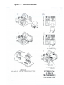
1
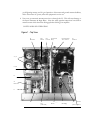
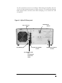
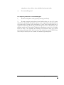
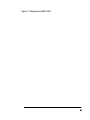
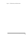
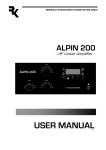
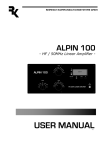
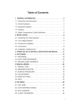
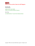
MODEL
99
Operating Manual
Alpha 99
Power Amplifier
i
Manual Alpha 99 Rev 1.doc
ALPHA 99
Operating Manual
ALPHA POWER PRODUCTS
Warnings posted in this manual should be read and thoroughly understood by users.
Failure to perform procedures properly may result in amplifier damage, fire hazard, or
electric shock.
© Radio Alpha Products Inc.
6185 Arapahoe Road • Boulder, CO 80303
Phone 303.473.9232 • Fax 303.473.9660
ii
DISCLAIMER
Information in this document is subject to change without notice. Information provided by Radio Alpha
Products Inc.® is believed to be correct and reliable. However, no responsibility is assumed by Radio Alpha
Products Inc., unless otherwise expressly taken. Companies, names, and data used as examples are fictitious,
unless otherwise noted.
No part of this document may be reproduced or transmitted in any form or by any means, graphic, electronic,
or mechanical, for any purpose without the express permission of Radio Alpha Products, Inc. Radio Alpha
Products, Inc. may have patents or pending patents, trademarks copyrights, or other property rights covering
the subject matter in this document. The furnishing of this document does not give you license to these
patents, trademarks, copyrights, or other intellectual property, except as expressly written in any license
agreement form.
Radio Alpha Products Inc.
6185 Arapahoe Road
Boulder, CO 80303-1401 USA
Read this entire manual and all other publications pertaining to the work to be performed before you install,
operate, or maintain this equipment. Practice all product safety instructions and precautions. Radio Alpha
Products, Inc. provides information on its products and associated hazards, but it assumes no responsibility for
the after-sale operation of the equipment or the safety practices of the Owner or User. See Warranty and
Notices Appendix.
©Copyright 2002 by Radio Alpha Products Inc.
All rights reserved.
iii
iv
Table of Contents
Introduction
7
General Description of the ALPHA 99 Amplifier
7
Equipment Shipped
7
Safety: Installation and Operation
7
Specifications, ALPHA 99
9
Before Installing Your Alpha 99
11
AC power Source
12
Antenna
12
Coax and Connectors
13
Air Flow
13
RF Safety
13
Before Operating Your Alpha 99
14
Figure 1 - Top View
15
Carefully unpack amplifier and transformer.
17
AC Primary Connections & Amplifier Grounding.
17
Install the transformer.
17
AC Primary Connections & Amplifier Grounding
18
Power Cord Connections
19
RF Grounding
20
Replacing the Amplifier Cover
20
Internal Blower/Auxiliary Fan
20
Amplifier/Station Interconnections
22
Coaxial Cable Types & Connectors
22
T/R Control Cable
22
ALC
22
Figure 5 - Alpha 99 Rear panel
23
Control Functions
24
Turning on the amplifier:
26
Table 1 – Preliminary Tuneup Settings
28
Tubes
30
Interlocks
30
5
Manual Alpha 99 Rev 1.doc
Fuses
31
Plate Overcurrent Relay
31
Idling Plate Current And Electronic Bias Control (Ebs)
31
RF & Mistuning Protection
31
Preventive Maintenance
33
Figure 6 – Simplified Chassis Schematic
38
Figure 7- Display Board ABX-X400
39
Figure 8 – Control Board ABX-X401
40
Figure 9 – Control Board ABX-X401
41
Figure 10 – T/R Status Board, Multimeter Switch and Switch Matrix Board
42
Figure 11 – Power Supply Board
43
Figure 12 – HV Filter and Screen Supply Board
44
Figure 13 – T/R Status Board and Multimeter Switch
45
Figure 14 – Output Wattmeter Board
46
Figure 15 – Center Partition Board
47
Figure 16 – Tube Deck BCX-X413
48
Figure 17 – Wiring Harness
49
ALPHA PRODUCTS WARRANTY
50
6
Manual Alpha 99 Rev 1.doc
1
Section
IMPORTANT!
Critical precaution during installation of your Alpha 99:
While the cover is removed to install the power transformer, make
sure that the tubes are properly installed as described in Section 2.
Failure to do this may cause severe damage or destruction of both
tubes. Such damage is not covered under warranty.
Introduction
General Description of the ALPHA 99 Amplifier
The ALPHA 99 is a self-contained HF Linear power amplifier capable of continuous
operation at 1500 watts peak power output on SSB, keyed CW, SSTV, RTTY, digital
modes or FM, with no time limit. If periods of “continuous-key-down” carrier
operation will exceed 5 minutes, or if the amplifier is to be operated from 50 Hz AC
source, the optional auxiliary cooling fan available from Radio Alpha Products must be
installed to avoid possible damage not covered by the warranty.
Owner Assistance
Assistance is available from Alpha Power Customer Support at 303.473.9232 x.. 141,
or by fax at 303.473.9660, or by email at alpha-service@Radio Alpha Productsinc.com.
Equipment Shipped
The Alpha 99 amplifier ships in two cardboard cartons. One carton holds the power
transformer and weighs 43 pounds; the second carton contains the amplifier and
weighs 38 pounds.
Safety: Installation and Operation
The Alpha 99 amplifier is designed to meet international safety standards and FCC
regulations. However, one should always remember that the equipment works with
high voltages that are LETHAL!
7
Manual Alpha 99 Rev 1.doc
This operating manual holds information, cautions and warnings that must be followed
to ensure safe installation and operation. Read Section 1 before attempting to unpack
or operate the amplifier.
Warnings: What Not to Do
Never open the amplifier case without unplugging the unit from
the wall outlet.
Never stick objects into holes in the case.
Never touch an antenna during transmission.
Never attempt to turn on the amplifier without the cover in place.
Never turn the amplifier back on after a hard fault without waiting
at least 20 seconds.
Always resist the temptation to immediately hit the ON button
after the amplifier faults to power off.
Warnings posted in this manual should be read and thoroughly
understood by users. Failure to perform procedures properly may
result in amplifier damage, fire hazard, or electric shock.
Radio Alpha Products Inc. ® Alpha 99
8
Specifications, ALPHA 99
Frequency Coverage:
All amateur bands 1.8-29.7 MHz* plus
most non-amateur frequencies 6.0-19.0
MHz and 20.0-30.0 MHz.
Power Output:
1500 watts peak all modes, including
SSB, CW and continuous or modulated
carrier. Carrier operation (e.g., A0,
RTTY or FM) for more than 5 minutes
at or near maximum rated power
requires use of the auxiliary cooling fan
accessory.)
Drive Power:
50 to 60 watts nominal for rated output.
Power Gain:
Nominally 14 dB, a power increase of 25
times.
Input Impedance:
50 ohms nominal, unbalanced; VSWR
<1.5:1.
Output Impedance:
50 ohms unbalanced.
Maximum Load VSWR:
2:1 at full rated power output.
VSWR Trip:
Automatic standby
power >250 watts.
Intermodulation Distortion:
30 dB below rated output.
Harmonic Output:
<-60 dBc.
Tubes:
Two Svetlana 4CX800 ceramic-metal
tetrodes.
Cooling:
Full-cabinet, ducted forced air using
cushion-mounted centrifugal blower.
Automatic Level Control (ALC):
Negative from 0, adjustable.
Primary Power:
190-250 or 90-130 VAC nominal, 50-60
Hz, fused at 20 amperes.
Power Transformer:
3+ kVA with strip-wound Hipersil core.
when
reflected
Radio Alpha Products Inc. ® Alpha 99
9
Protective Functions:
Grid and screen current limiting; trip to
standby (automatic reset) for excessive
VSWR or average plate current, RF arc,
severe mistuning; AC off trip for HV
fault; primary and step-start fuses; cover
AC interlock and HV crowbar switches;
AC inrush-current limiting (Step-start).
Status Indicators:
STANDBY, WAIT (initial turn-on time
delay), OPERATE and FAULT LEDs.
Metering:
Dedicated, full-time LED bargraphs
display forward and reflected rf power;
grid current LEDs; LED bargraph
selectable among plate voltage, plate
current, and tune-up functions.
Size:
7.5” H x 17” W x 16.5” D
(19x43x39cm) excluding controls, feet,
and connectors.
Weight:
66lb. (30kg) net, 75lb (34kg) ship; two
cartons.
Note: Radio Alpha Products reserves the right to change design and/or specifications
without prior notice or obligation.
*FCC rules do not permit new amateur amplifiers to be operable on 24-30 MHz as
delivered within the United States and possessions. The Alpha 99 as shipped to any
US address will not be operable on 21 MHz and above. Owners who send a copy of
their authorizing license to Radio Alpha Products will be provided information on
“unlocking” these bands.
Radio Alpha Products Inc. ® Alpha 99
10
WARNING –READ THE MANUAL CAREFULLY BEFORE INSTALLING
YOUR ALPHA 99.
The ALPHA 99 is extremely easy to install, but failure to carry out
each procedure exactly as described in the manual is likely to lead to
amplifier damage which is not covered under warranty. Damage to
other station equipment also may result.
Before Installing Your Alpha 99
1. Be careful not to twist or warp the chassis when handling the amplifier with its
cover removed. Never lift the chassis by a corner, especially when the transformer
is in place. Never apply AC power without the transformer properly and fully
installed.
2. When installing or removing the transformer, move carefully and follow the
instructions in this manual exactly. Insure that all connectors are properly mated
and fully seated. Don’t force them! Tuck the lifting handle out of the way so that
the interlock can close.
3. Ensure that both tubes are solidly seated in their sockets with the red silicone
rubber chimneys firmly seated against the chassis. The delrin posts over the tubes
are to keep the tubes from shifting during transit, they can be removed but should
be replaced if the amplifier is to be shipped.
4. Connect the green conductor in the ALPHA 99 power cord only to the power
source neutral or ground. Connecting the green wire to a “hot” line is almost
certain to cause immediate damage. Triple check your wiring before
plugging in!
5. Make sure the primary power tap is connected to the tap closest to your actual AC
voltage. See Manual Section 3. You should mesure your line voltage with a digital
meter for accuracy.
6. Solidly ground all station equipment together. Heavy braid, such as the outer
conductor of RG-8/U coaxial cable, is recommended for the purpose. This is
important for personal and equipment safety as well as to avoid feedback.
7. Never install cover screws longer than ¼”. Longer screws may penetrate
internal boards or wiring and cause severe damage. Make sure each screw hole in
the cover is aligned with its corresponding captive nut in the chassis before
inserting screws.
8. Remove the fan retaining screws before operating the amplifier, the screws can
interfere with fan operation.
Radio Alpha Products Inc. ® Alpha 99
11
Station Engineering
Considerations
The 99 is capable of dramatically improving the performance of your amateur station. It is
important that you observe good engineering practices to achieve all the benefits of such a
station in a safe and reliable manner. This section provides a few hints for important
operational considerations, but it is recommended that the user also consult a good source
of general information such as “The Radio Amateur’s Handbook” by the ARRL, especially
if this is the first high-power amplifier you have used.
AC power Source
If you do not have a 220V AC outlet in your shack, you will need to get a licensed
electrical contractor to install one. A minimum of a 20 amp capacity is required. A 20
amp breaker on your 220V circuit is sufficient. For this reason, the amplifier is not
shipped with a power plug. Select a location for the outlet as close as possible to where
you expect to operate the 99. If you are not sure, or contemplate moving the amplifier,
it may be cheaper to get a second outlet installed at the same time. Ask your contractor
for two or three matching plugs while he is there, as there are several styles of
connector available. Ask the contractor to measure the voltage and record it, so you
can set the line voltage tap on the 99 appropriately. If he can, ask him to tell you the
line voltage with a 10 Amp current draw, and use this value for setting the transformer
tap. The Alpha 99 can run on a 110V AC outlet. However, you WILL NOT achieve
full legal limit output in this case. If the amplifier is connected to a 110V AC outlet,
you should not expect more than 1000 watts output.
Antenna
Many antennas which are suitable for general use are unsuited for operation with a full
1500 watts of power. At this power level in a 50 ohm circuit, the RMS current is 5.5
amps and the peak RF voltage is 387 volts. With a 2:1 SWR, these values double to 11
amps and 775 volts. The voltage and current at various points in or on your antenna
can actually be many times these values. On a simple dipole with sharp wire ends,
corona (localized ionization) can easily occur. Corona can (and has!) lead to fire in
nearby objects. Traps in beams and verticals can heat up significantly during high
power operation. Instances of melting or flashover of traps have occurred in many
installations where insufficient thought has been given to their ratings. If an antenna
has been deployed for a long period of time, it may be worth taking it down for
inspection prior to full power operation. If any insulators are cracked or show signs of
“tracking”, replace them. Doubling-up on insulators is also easy to do, and may save
problems. If there is any chance of people or objects coming close to the antenna, take
steps to move it higher, or place barriers so that this cannot happen. Check the SWR
of your antenna. If you have a favorite part of any band you use most often, consider
adjusting the antenna for minimum SWR in this part of the band.
Radio Alpha Products Inc. ® Alpha 99
12
Coax and Connectors
The importance of a well constructed feedline system cannot be overstated. After all,
the purpose of the amplifier is to provide approximately 2 S units (12+ dB) of
improvement in your radiated signal. All too often, installations are encountered where
cheap/poor/under-rated/old coax and connectors are probably responsible for at least
one S unit of degradation. This means you could have bought a 375 Watt amplifier and
achieved the same radiated signal by buying good quality feedline components! Use the
lowest loss 50 ohm coaxial cable you can get your hands on. Use new, clean
connectors installed per the manufacturer’s recommendations. Clean the connectors
after soldering them, and before mating them with the amplifier. Make sure any excess
solder is removed from the connector, likewise any fragments of braid etc. Never use
old coax, which may have had moisture penetrate under the jacket. Run the coax in
straight lines as much as possible. Support it frequently using non-compressive clips so
that it does not hang or stretch under its own weight. Avoid sharp bends (most
manufacturers will specify a minimum bend radius for their product). Make sure the
transition from feedline to antenna is waterproof. Provide for disconnection of the
feedline when not in use.
Air Flow
It is critical that the 99 air flow is unrestricted in any way. Keep the top of the amplifier
clear of any restrictions. If you are mounting the amplifier in a console, make sure that
the exhaust air is properly and fully removed from the console. Poorly designed
consoles can result in outlet air being drawn back into the amplifier air intake and
recirculated, getting hotter and hotter, resulting in degraded amplifier performance or
even failure. If you are designing your own console, consider putting in additional fans
and/or ducting to deal with waste heat. Try to minimize the possibility of dust or other
contamination getting drawn into or falling on the amplifier. It is also advisable to
periodically clean the dust out of your amplifier for continued flawless operation.
RF Safety
The FCC requires users to check their installations for compliance with published
values for allowable exposure to RF fields. This information is available in ARRL
publications, FCC printed rules, and on the web. Radio Alpha Products strongly
recommends that this be done for any installation, both fixed and at an expedition or
contest site.
If you have any questions regarding engineering your 99 into your amateur radio
station, do not hesitate to call Radio Alpha Products Alpha Technical Support.
Radio Alpha Products Inc. ® Alpha 99
13
WARNING –READ THE MANUAL
CAREFULLY BEFORE OPERATING YOUR
ALPHA 99.
The ALPHA 99 is extremely easy to operate, but failure to carry out each
procedure exactly as described in the manual is likely to lead to amplifier damage
which is not covered under warranty. Damage to other station equipment also
may result.
Before Operating Your Alpha 99
1. You must set transceiver power output properly. Virtually all damage to date has resulted
directly from severe overdrive. The ALPHA 99 requires about 50 watts drive for full
rated output. Damage caused by applying several times rated drive power to the
ALPHA 99 will not be covered under warranty. Fortunately, most modern
transceivers maintain quite consistent output from band to band and mode to mode if set
up properly.
Setting only the transceiver POWER or RF PWR control IS NOT SUFFICIENT.
Several popular transceivers can generate RF spikes of 200-300W or more unless the
transceiver’s internal ALC (drive level) is also adjusted carefully according to its
manufacturer’s instructions. This typically is done with a knob labeled DRIVE (IC-781,
FT-1000) or PROCESSOR OUT (TS-940, TS-950). On SSB, when speech processing is
not, adjust the MIC or MIKE controls.
2. The ALPHA 99 “faults” into STBY or OFF when unsafe operating conditions
occur. If this occurs, the fault will clear after 30 seconds and if you are certain that you
have taken care of the problem that caused the fault, you may turn the amplifier back to
operate and proceed with use.
3. On any frequency where your antenna VSWR exceeds 1.5:1, it’s important to
carefully tune the ALPHA 99 for a proper match. The Alpha 99 does not contain an
antenna tuner. The SWR will need to be tuned via the antenna or an external tuner
connected to the output of the Alpha 99.
4. If you tune the amplifier for maximum power output and then decide to operate the
ALPHA at power output much different from 1.5kW, it must be re-tuned for efficient
and RF-clean operation.
5. Induced energy from nearby electrical storms or other power transients may damage
components. Such damage is not covered under warranty. It is important to use a
Radio Alpha Products Inc. ® Alpha 99
14
good lightning arrestor, and it’s good practice to disconnect and ground antenna feedlines,
and to disconnect AC power, when the equipment is not in use.
6. Never use an automatic antenna tuner into or through the 99. This will cause damage to
the Input Wattmeter & Input Relay. Note that many popular transceivers have built in
antenna tuners which should be disengaged when driving your amplifier.
HAPPY AND SAFE OPERATING.
Figure 1 - Top View
L4
RF Choke
BL1
Blower
HV
K2 Vacuum
Crowbar Relay
L8
C22
C32
(under C22)
P1 Transformer
AC Connector
S3
Interlock
BR1
HV Bridge
J1 HV Connector
V1, V2
C19,20
L6
S6
Bandswitch
L7
Power Supply
Board
J2 LV Connector
Radio Alpha Products Inc. ® Alpha 99
15
2
Section
Overview of Amplifier
Capabilities
It is extremely important to thoroughly review the Installation and Operation sections of this manual
before attempting to use the ALPHA 99. Failure to do so could result in serious damage not covered
under warranty.
Continuous RF Output. The 99 is capable of 1.5kW continuous RF output on all
commonly used modes and on any authorized amateur frequency from 1.8 to 29.7
MHz.
Compatibility with popular amateur transceiver and exciters.
approximately 50-55 watts peak RF drive for 1.5kW output.
It requires
Capable of full CW break-in, QSK and all digital modes when used with any
appropriate transceiver.
Protective functions built in. The control system incorporates protective functions
that minimize the probability of accidental damage to the amplifier or its power
tubes. In most cases, when one of the protective functions is “tripped,” the
amplifier will go to Standby.
Optional auxiliary cooling fan available. We recommend using the external
auxiliary fan for extended RTTY or other “locked key” service. This is available
separately from Radio Alpha Products. The cooling fan is required for operation
with a 50Hz power source.
Radio Alpha Products Inc. ® Alpha 99
16
3
Section
Unpack and Prepare for
Operation
(Refer to Figures. 1-5, pages 13, 19, 21)
Carefully unpack amplifier and transformer.
Inspect both for physical damage. Save all packing material for future use.
AC Primary Connections & Amplifier Grounding.
Remove the amplifier top cover. Primary voltage taps are selected at the terminal strip
numbered “1” to “7” and located on the mains board mounted on the chassis center
divider, left of the transformer. Connect the two wires labeled “A” and “B” for the line
voltage to be used, as shown in the following table. The two short jumper wires
supplied are not used on 190-250V, but must be connected as shown for operation on
90-130V mains.
Install the transformer.
Only one possible transformer orientation allows mating all its connectors without
straining leads.
Warning! The transformer is very heavy and must be moved with due
caution using only the lifting handle.
Lift the transformer high enough to clear the right side chassis lip and move it sideways
into the chassis. USE CAUTION! PROCEED SLOWLY to avoid damaging wires
or components. From underneath, insert the supplied bolts with washers through the
clearance holes in the chassis and into the nuts in the transformer base. CAUTION!
Mate transformer connectors carefully and gently to insure that all connector pins
engage correctly and fully.
While the top cover is removed, make sure each tube are firmly seated in its socket,
rubber exhaust chimneys is fully and correctly installed, and anode connector is tightly
clamped to each tube. The silicone rubber chimneys installed on the 4CX800 tubes are
17
Manual Alpha 99 Rev 1.doc
an absolutely essential part of the cooling system. Make sure the chimneys are straight
and fully installed so that the bottom of the chimney is firmly against the tube deck and
completely covers the airflow openings in the deck. Tube cooling air must exit only
through the tube anode fins; it must not be allowed to escape outside them. Failure to
ensure proper cooling airflow may result in tube damage or destruction which is not
covered under warranty.
AC Primary Connections & Amplifier Grounding
Primary voltage taps are selected at the terminal strip numbered “1” to “7” and located
on the mains board mounted on the chassis center divider, left of the transformer.
Connect the two wires labeled “A” and “B” for the line voltage to be used, as shown in
the following table. The two short jumper wires supplied are not used on 190-250V,
but must be connected as shown for operation on 90-130V mains.
PRIMARY
“A” Terminal “B” Terminal
Blower*
Jumpers
230-250V
4 **
2**
4 & 2**
Not used
for
190
250V operation
210-230V
4
3
4&3
Not used
for
190
250V operation
190-210V
5
3
4&3
Not used
for
190
250V operation
110-130V
4
6
4&7
1 - 2, 6 - 7
90-110V
5
6
4&7
1 - 3, 6 – 7
* The blower wires are the 2 black wires marked “4” and “X”, ( 4 to terminal 4, X to 2,
3, or 7 per table). Optional external muffin fan has 2 black wires, one is connected
with blower wire 4 and the other to the same terminal as blower wire X (2, 3, or 7 per
table)
** Factory settings.
NOTE: If you intend to operate the amplifier on any of the 90 - 130V
settings, the two lower fuses on the rear panel (2 amp) will have to be
changed to 5 amp to allow for the increased in-rush current.
Radio Alpha Products Inc. ® Alpha 99
18
NOTE: Do not operate amplifier without the cover in place and all
cover screws installed. Do not operate amplifier without a good RF
ground connection on the rear panel ground terminal.
Power Cord Connections
WARNING!
To avoid the hazard of a potentially fatal electric shock and/or severe
damage to the ALPHA 99 and other equipment, always use an AC
plug that is appropriate for the primary mains voltage, current rating
and configuration. NEVER use 120V-type plugs and power
receptacles for 190-250V circuits.
ALWAYS use grounding type AC connectors which conform to local codes and
ensure that the green wire in the Alpha 99 power cable is wired only to the AC mains
safety ground (or to neutral, as may be necessary with a 240V circuit configured 120VN-120V without a separate ground, commonly found in the US).
The green conductor in the power cord is wired to the ALPHA 99 chassis. It MUST
be connected only to the power source safety ground or neutral. The black and white
power cord wires connect to the two “hot” wires of the AC source; either wire may be
connected to either side of the line. For best results use a dedicated 200-240V branch
circuit of #10 AWG copper wire or equivalent, rated at 20A, to feed the amplifier.
Important information concerning operation from 90-130V AC
Electrical power equipment will draw twice as much primary current from 120V mains
as from 240V mains. Therefore, operating the ALPHA 99 on a typical 120V/20A
household circuit without exceeding the 20A circuit rating will limit maximum peak
power output to about 600-1000 watts. Maximum possible RF output power for any
particular primary AC voltage and current capacity may be estimated as:
Po max = (VLINE x ILINE) / 2.3.
For example, if the Alpha 99 operates from a circuit which is capable of delivering
115V AC at a maximum current of 20A, with no other loads connected to the circuit,
maximum peak RF output possible without tripping the 20A breaker (or fuse) is
approximately:
Po max = (115V x 20A) / 2.3 = 2300/2.3 = 1000 watts.
Radio Alpha Products Inc. ® Alpha 99
19
If the same circuit also supplies a transceiver drawing peak line current of 5A and a
lamp drawing 1A, only 20-5-1 = 14A is available for the amplifier and maximum
possible output is about:
Po max = (115V x 14A) /2.3 = 1610/2.3 = 700W.
RF Grounding
A ground stud with wing nut is provided on the rear of the chassis. Connection
should be made from this stud to a good RF earth ground, such as a copper water pipe
or driven rod, via heavy copper braid or strap. CAUTION: When using any high
power amplifier, failure to connect ALL station equipment to a good common ground
may allow RF feedback to leak into the transceiver and cause severe signal distortion.
Replacing the Amplifier Cover
Use only the 6-32 screws supplied with the amplifier and do not tighten any of the
screws until all are started. Do not attempt to operate the amplifier with the cover
removed. This WILL cause damage to the Alpha 99 and may also lead to injury or
death to the operator.
Internal Blower/Auxiliary Fan
Remove the blower motor shipping hardware (two 10-32 bolts, fiberwashers, rubber
shim) from rear chassis wall. Save this hardware! It must be reinstalled whenever the
chassis is transported. For heavy-duty use or 50 Hz operation, the optional auxiliary
fan is required.
Radio Alpha Products Inc. ® Alpha 99
20
Figures 2 - 4 - Transformer Installation
Radio Alpha Products Inc. ® Alpha 99
21
4
Section
Amplifier/Station Interconnections
See figure 5
Coaxial Cable Types & Connectors
Connect the transceiver RF output to the ALPHA 99 RF INPUT with 50 ohm coaxial
cable- RG-58C/U or equivalent. A 6 ft. cable is supplied for this purpose.
Coaxial cable from the 99 RF OUTPUT to antenna should be RG-8A/U, RG-213/U,
or equivalent high quality type with a PL-259 UHF-type plug on the amplifier end.
RG8X cable is not recommended.
T/R Control Cable
The Alpha 99 has a full break-in vacuum relay QSK system requiring only the normal
interconnection when used with a modern QSK transceiver. The Alpha 99 requires a
contact closure (short circuit) on transmit from its RELAY jack center pin to chassis.
This function is supplied by the transceiver, usually from a dedicated relay that is
normally open in receive and closed in transmit. Shielded wire should be used for the
T/R control cable. The Alpha 99 end must be fitted with a common phono (RCAtype) plug and the other end with a connector suitable for the transceiver.
The T/R relay contact must close before application of RF drive. The Alpha 99
protection circuitry prevents “hot-switching” with RF drive applied. Modern
transceivers have the proper time delay between keyup and the start of the transmitted
signal to allow the Alpha 99 to follow the CW keying. If a T/R timing problem is
suspected, connect the CW keyer to the RELAY jack on the Alpha 99, and connect a
cable from KEY OUT on the amplifier to the keying input of the transmitter.
ALC
The use of ALC output on the rear of the 99 chassis is not normally needed or
recommended when the ALPHA 99 is used with modern transceivers. However, the
Alpha 99 does generate a negative ALC control voltage that can be fed back to most
transceivers if required, to minimize the possibility of overdriving the amplifier. This
external ALC voltage is available at the amplifier’s rear panel ALC jack via a common
phono connector. Alpha 99 grid current exceeding about 3mA will initiate ALC and
light the green GRID LED. About 5-10mA yields full ALC output-nominally -10 Vdc
- and the red GRID LED lights. If the exciter requires a lower ALC voltage, the Alpha
22
Manual Alpha 99 Rev 1.doc
99 ALC potentiometer may be set accordingly. While driving the amplifier, adjust the
ALC pot to limit maximum transceiver output as desired. We recommend contacting
Radio Alpha Products customer service before attempting to use external ALC with
the Alpha 99.
Figure 5 - Alpha 99 Rear panel
RF OUTPUT to
Key In Line from
antenna
radio
ALC ADJUST pot.
Key Out Line (optional)
to radio.
RF INPUT from radio 5060 watts.
ALC OUTPUT to radio
(not
recommended
with modern
radios)
Radio Alpha Products Inc. ® Alpha 99
23
5
Section
Initial Set-up and Tuning
Control Functions
(See front cover photo)
BAND
Use to select amateur band desired (in MHz).
TUNE
Sets output tank circuit to resonance. Higher frequencies
tend to tune
toward the “0” end of the dial scale, while
lower frequencies tend to tune further toward the “100”
end.
LOAD
Sets amplifier plate loading and determines the power level
at which best efficiency and linearity are achieved. In
general, loading is heavier at greater scale settings. Higher
frequencies tend to load more toward the “100” end of the
dial scale and lower frequencies toward the “0” end.
POWER
Press ON to apply primary AC power to the amplifier or to
reset power if the plate overcurrent relay has tripped. Press
OFF to remove primary AC power.
OPR/STBY
Operate places the amplifier in-line. With the 99 off, in
STandBY, or in warm-up with the WAIT LED lighted, the
amplifier is bypassed and the exciter is connected directly to
the antenna.
Metering LEDs
Bargraphs
RF OUTPUT
REFLECTED
& Separate bargraphs provide instantaneous full-time display
of peak values.
and Red and green “GRID” LEDs indicate, respectively, that
normal peak drive has been reached and the onset of
Radio Alpha Products Inc. ® Alpha 99
24
POWER:
overdrive and flattopping. A switch-selected
monitors three additional functions:
bargraph
TUNE:
Permits a simple and safe tune-up procedure to be
performed at low output power. See section Tune-up
below.
IP:
Plate current, 1.5 amperes full scale (approximately 75 mA
per segment).
HV:
Plate voltage, 3000 VDC full scale (150 V per segment).
Tune-up
The objective of tune-up is to adjust the amplifier (and the drive applied to it) to obtain
optimum efficiency and linearity at the desired output power. Any linear amplifier
must be adjusted for optimum efficiency and linearity at each specific power level. If
operation at higher power is then attempted without appropriate readjustment, the
result will be flattopping, “splatter,” and (usually) excessive amplifier grid current. If
operated at a much lower power level than it has been adjusted for, the amplifier’s
efficiency decreases considerably.
Grid Current
The ALPHA 99 operates in Class AB2 when delivering maximum output power
consistent with excellent linearity. A small amount of grid current flows and the green
GRID MIN LED lights as drive approaches the optimum level. The green GRID
LED will flicker on SSB voice peaks, and light under CW/SSTV/RTTY carrier
conditions.
As overdrive approaches, grid current increases rapidly and the red GRID MAX LED
lights. At maximum output and efficiency, the red LED lights dimly; full illumination
of the red LED indicates overdrive and must be avoided. If the red LED lights before
the desired value of plate current and/or power output is reached, readjust amplifier
loading before continuing.
On SSB, optimum output consistent with good linearity occurs when the green GRID
LED lights on most voice peaks and the red LED flickers dimly only on the highest
peaks.
Excessive grid current results from overdrive and/or inadequate loading. The solution
is to reduce drive, and/or increase amplifier loading. The 99’s 4CX800A/GU74b
tubes are well protected and these adjustments tend to be less critical than in many
Radio Alpha Products Inc. ® Alpha 99
25
other amplifiers.
ALC
The 99 grid current limiting circuits provide substantial tube protection against possible
damage. The ALC voltage generated by the 99 is for external feedback to transcievers.
It cannot control the amplifier itself and is not applied internally. If ALC control is
required, a connection must be made from the 99 to the transceiver ALC input.
Warm-up Procedure
NOTE: The forward and reflected power LED bargraphs and GRID LEDs are peakresponding.
BEFORE INITIAL TUNE-UP, MAKE SURE A SUITABLE ANTENNA OR 50
OHM DUMMY LOAD IS CONNECTED TO THE 99. Leave the amplifier off or
in standby and apply exciter power to make a forward vs. reflected power check. If
reflected power is less than ten percent of forward power, the VSWR is lower than 2:1
and it is safe to proceed with tuneup.
Turning on the amplifier:
1.
2.
3.
Place the OPR-STBY switch in STBY (standby).
Rotate the multimeter selector switch to HV.
Depress POWER/ON. If any of the following does NOT occur, depress
POWER/OFF switch immediately and investigate before proceeding:
a.
The blower starts (note air exhausting above tubes).
b.
The multimeter bargraph automatically displays HV; it should indicate
approximately 2.8 to 3.0 KV.
c.
The WAIT LED is lighted
IMPORTANT: EXHAUST AIR MUST BE DETECTABLE FROM THE TOP
VENTS: If it is not, TURN OFF the amplifier immediately and verify that the exhaust
chimneys are properly positioned over the tubes. When the warm up delay is complete
(about 150 seconds), the WAIT LED will extinguish. The ALPHA 99 is now “ready”.
Radio Alpha Products Inc. ® Alpha 99
26
Radio Alpha Products Inc. ® Alpha 99
27
1. Tuning Up for Operation at 1,500 Watts RF Output
Preset BAND, TUNE, and LOAD controls to the nominal positions given in Table 1,
below*:
Table 1 – Preliminary Tuneup Settings
Band (MHz)
Frequency (MHz)
Tune
Load
1.8
1.8
3.5
3.5
3.5
7
10
14
18
21
24
28
28
28
1.8
2.0
3.5
3.75
4.0
7.15
10.13
14.2
18.1
21.2
24.9
28.0
28.6
29.7
60
20
67
58
50
45
15
70
50
40
65
32
24
18
14
65
40
60
75
35
26
40
55
65
60
72
74
76
*Each Alpha 99 shipped from our factory will include an individual table showing the
tune and load settings we used to achieve full output power on that amplifier into a 50
ohm delivery load. These settings may vary slightly from those in the manual.
NOTE: Final TUNE and LOAD settings will vary with the operating frequency,
antenna characteristics and power level.
2. Reduce transceiver carrier output control to ZERO.
3. Press OPR (operate) on OPR-STBY switch. OPR LED should light.
4. Select TUNE function of the multimeter bargraph.
IF AT ANY TIME IN THE FOLLOWING PROCEDURE THE AMPLIFIER
FAILS TO RESPOND AS DESCRIBED, REMOVE DRIVE IMMEDIATELY!
5. Switch transceiver to CW and increase its carrier output to approximately 15 watts
(99 output apporx. 300-500 watts).
6. Adjust TUNE control to deflect the TUNE LED maximum leftward.
Radio Alpha Products Inc. ® Alpha 99
28
7. Adjust LOAD control to place the illuminated TUNE LED at the “V” mark on
the TUNE scale.
8. Repeat steps 6 and 7 at least twice.
9. Increase excitation until 99 output is about 1500 watts.
10. Repeat steps 6 and 7 at least twice.
11. Touch up TUNE for maximum power output.
The ALPHA 99 is now correctly tuned to deliver 1500 watts RF output on SSB, CW,
FSK, SSTV and FM. The TUNE LED normally fluctuates during modulation or
keying. Illumination of the first red LED on the RF OUTPUT bargraph indicates
output has exceeded 1500 watts.
To operate at reduced power in any mode, decrease drive (i.e. transceiver power
output) and doublecheck all tune settings for efficient and RF-clean operation.
Radio Alpha Products Inc. ® Alpha 99
29
6
Section
Use and Maintenance
Tubes
The 4CX800A/GU74b tubes used in the ALPHA 99 are very rugged and normally
operate with a large margin of safety. They should provide outstanding service for
many years if not damaged by abuse - especially overdrive or blockage of cooling
airflow. Allow at least twelve inches (31 cm) unobstructed clearance around the air
intake and exhaust areas.
Stacking equipment is not recommended.
Never allow key-down plate current to exceed 1.5 amperes for more than one or two
seconds. If you do and a plate current trip occurs, it will automatically reset in about 4
seconds if the amplifier is returned to receive (key-up).
Never allow the red GRID LED to stay brightly illuminated for more than a second.
Frequent on-off AC power cycling may shorten tube life. It’s better to leave
equipment in standby for several hours than to cycle power repeatedly on-off-on-off
over the same period.
Interlocks
The ALPHA 99 is equipped with a cover interlock switch intended to remove primary
power from the amplifier, and a crowbar to short-circuit the high voltage to chassis
whenever the cover is lifted. These interlocks are designed to protect against
dangerous electric shock resulting from accidental contact with the lethal voltages
inside the amplifier.
WARNING!
ALWAYS DISCONNECT THE AC LINE CORD FROM THE POWER
SOURCE BEFORE REMOVING THE TOP COVER FROM THE 99 FOR
ANY REASON!
Radio Alpha Products Inc. ® Alpha 99
30
Cover interlocks are intended only as back-up protection against accidents. Never
depend on them! Always disconnect the power cord from the AC mains before
removing the cover! Interlock switches should never be disabled for any reason.
Fuses
Never replace any fuse with one of a different type or greater current rating. Blowing
of one or both primary line fuses indicates that the maximum safe average power
capability of the amplifier has been substantially exceeded or that an equipment failure
has occurred. USE ONLY 20 AMP, 250 VOLT RATED FUSES for 190-220 VAC
service.
Slow-blow fuses F3 and F4, located above the primary line fuses, may prevent damage
to the step-start resistors and HV rectifiers in the event of abnormal turn-on
conditions or HV faults. If the AC interlock is defeated and primary power is applied
while the HV crowbar is closed, the step-start fuses normally will blow.
DAMAGE RESULTING FROM USE OF A FUSE OF INCORRECT SIZE OR
TYPE WILL NOT BE COVERED UNDER WARRANTY AND MAY VOID
THE WARRANTY.
Plate Overcurrent Relay
This relay will quickly turn off the amplifier in the event of grossly excessive plate
current or fault in the high voltage circuitry. The relay will not prevent tube or other
damage due to either short or long term overdrive or improper tuning. It is the
operator’s responsibility to ensure safe tuning, drive, and general operating conditions.
Should the overcurrent relay trip, remove AC power from the amplifier, then
determine and correct the cause of the trip before turning the 99 on again.
Idling Plate Current And Electronic Bias Control (Ebs)
Idling plate current of the ALPHA 99 is approximately 350 to 400 mA during
fullpower transmission. A detector senses RF drive, and reduces plate current to 30-50
mA during pauses in speech and key-up intervals, thus substantially reducing average
power
supply
loading,
heat
generation,
and
wasted
energy.
RF & Mistuning Protection
ALPHA/POWER’s exclusive circuit senses the beginning of any RF arc in, for
example, a TUNE or LOAD variable capacitor and automatically switches the 99 to
standby within a few milliseconds. This system has virtually eliminated RF arc damage
in current ALPHA amplifiers. The system similarly detects severe mis-tuning of the 99,
and if drive exceeds about 25 watts switches the amplifier to standby. The 25 watt
input trip threshold permits safe tuneup at low power levels using the TUNE indicator,
without aggravating and unnecessary trip-outs.
31
Manual Alpha 99 Rev 1.doc
32
Manual Alpha 99 Rev 1.doc
Preventive Maintenance
The amplifier interior, particularly high voltage areas, should be cleaned with a vacuum
cleaner and a soft bristle brush frequently enough to prevent visible accumulation of
dust. In extremely dusty conditions it may be advisable to secure a thin air filter of the
type used for window air conditioners across the air intake on the rear panel. The
ALPHA accessory cooling fan also should be installed to insure adequate cooling
airflow.
There are no user-accessible lubrication points in the amplifier. Do not apply oil or
grease to any of the components. The exterior of the ALPHA 99 may be cleaned with
a mild household liquid detergent such as Formula 409 or Fantastik. Do not use
chemical solvents, as these may severely damage the front panel or cabinet finish.
Never use an abrasive cleaner.
Radio Alpha Products Inc. ® Alpha 99
33
7
Section
Troubleshooting Hints
*NOTE: FCC rules do not permit new amateur amplifiers to be operable on 24-30
MHz as delivered within the US and possessions. As shipped to a US address, the
amplifier is not operable on 21 MHz and above. Owners who send Alpha Power
Customer Support a photocopy of their authorizing amateur license will promptly be
provided information on “unlocking” 12 and 10 meter coverage.
99 will not turn on; nothing happens when ON switch is pushed.
1)
External AC wiring, fuse or circuit breaker may be open.
2)
Amplifier cover not in place; cover safety interlock open.
3)
Fuse F1-F4 open or missing; check fuses with an ohmmeter.
4)
Step-start resistor R4 or R5 open.
Amplifier turns on but no HV is indicated by the multimeter LED bargraph.
1)
Multimeter selector switch in wrong position, e.g., Ip.
2)
Possible HV circuit fault.
3)
HV sampling resistor in power supply damaged.
4)
Transformer plugged into power supply incorrectly.
Amplifier turns on but no multimeter indications;
operative.
other LED bargraphs are
Radio Alpha Products Inc. ® Alpha 99
34
1)
Low voltage power supply problem.
2)
Defect or damage on control board.
Amplifier turns on but time delay will not complete; WAIT LED does not turn off.
1)
Defect or damage in timing circuitry on control board.
Amplifier turns on, time delay completes but amplifier will not transmit.
1)
Open T/R control line from transceiver to RELAY jack.
Radio Alpha Products Inc. ® Alpha 99
35
Amplifier transmits but red GRID LED often lights.
1)
Amplifier overdriven or underloaded; reduce transceiver output and /or
increase amplifier loading.
2)
Load VSWR (reflected power) exceeds 200W.
3)
Exciter output poorly controlled. External ALC may help.
Amplifier operates but green GRID LED will not light and plate current is low;
transceiver does not seem to be able to drive amplifier to its rated RF output
power level.
1)
External ALC control voltage to transceiver excessive (see Section 5,
Automatic Level Control).
2)
Input rf load resistor or bias circuitry damaged.
3)
Possible damaged or defective tube(s).
Receive signals disappear or are severely attenuated when switching from STBY
to OPR.
1)
RELAY (T/R) control cable from transceiver is shorted.
2)
Transceiver locked in transmit
Plate current indicated when amplifier is in STBY or receive.
1)
4CX800A/GU74b tube heater-to-cathode leakage or short.
2)
Tube bias supply or T/R bias switch faulty.
Distorted SSB signal; possible severe television interference.
1)
Excessive RF drive from transceiver and/or insufficient amplifier loading.
2)
Coaxial connector, coax feedline, antenna feedpoint balun, tuner, or antenna
trap arcing on voice peaks.
3)
RF feedback from antenna into transceiver via the transceiver power cord,
Radio Alpha Products Inc. ® Alpha 99
36
microphone or key cable, or other unshielded station patch cables.
4)
Poor station RF ground.
Low frequency audio hum on transmitted signal.
1)
Defective microphone cord (especially, broken ground lead).
2)
Dynamic (magnetic) microphone located within about two feet of 99 power
transformer. All dynamic microphones pick up some magnetically-coupled hum from
the external field of nearby power transformers. In cases where objectionable hum is
experienced while using the 99 and popular microphones such as the Heil series, the
problem usually can be resolved by keeping the microphone at least 18 to 24 inches
from the front of the amplifier and ensuring that transceiver mike gain, speech
processing, and internal drive (ALC) levels are not adjusted to exceed 10 dB. In rare
cases it may be necessary to use a ceramic or condenser type microphone.
Radio Alpha Products Inc. ® Alpha 99
37
Figure 6 – Simplified Chassis Schematic
Radio Alpha Products Inc. ® Alpha 99
38
Figure 7- Display Board ABX-X400
Radio Alpha Products Inc. ® Alpha 99
39
Figure 8 – Control Board ABX-X401
Radio Alpha Products Inc. ® Alpha 99
40
Figure 9 – Control Board ABX-X401
Page 2 of 2
Radio Alpha Products Inc. ® Alpha 99
41
Figure 10 – T/R Status Board, Multimeter Switch and Switch Matrix
Board
Radio Alpha Products Inc. ® Alpha 99
42
Figure 11 – Power Supply Board
Radio Alpha Products Inc. ® Alpha 99
43
Figure 12 – HV Filter and Screen Supply Board
Radio Alpha Products Inc. ® Alpha 99
44
Figure 13 – T/R Status Board and Multimeter Switch
Radio Alpha Products Inc. ® Alpha 99
45
Figure 14 – Output Wattmeter Board
Radio Alpha Products Inc. ® Alpha 99
46
Figure 15 – Center Partition Board
Radio Alpha Products Inc. ® Alpha 99
47
Figure 16 – Tube Deck BCX-X413
Radio Alpha Products Inc. ® Alpha 99
48
Figure 17 – Wiring Harness
Radio Alpha Products Inc. ® Alpha 99
49
ALPHA PRODUCTS WARRANTY
RADIO ALPHA PRODUCTS, INC WARRANTS AS FOLLOWS EACH NEW
ALPHA/POWER AMATEUR RADIO PRODUCT OF ITS MANUFACTURE, SOLD
AND USED IN THE UNITED STATES, ITS POSSESSIONS, AND CANADA:
Workmanship and all components except rf power tubes are warranted for FOUR YEARS
from date of original purchase if used exclusively in licensed amateur radio service.
WARRANTY IS VOIDED BY ILLEGAL SALE OR USE OF EQUIPMENT (e.g. U.S. sale
of export models).
Eimac power tubes are warranted by their manufacturer; Radio Alpha Products will assist
owners in securing warranty service if requested. Determination by Eimac as to warranty
covereage is binding on customer.
Svetlana power tubes are warranted by Radio Alpha Products for one year from date of
original purchase.
Warranty does not apply to repair of damage or failure resulting from improper maintenance or
repair, misuse, neglect, abuse, or improper installation, nor to units not operated in accordance
with specifications and instructions furnished by Radio Alpha Products, nor to units repaired
or altered by persons not authorized by Radio Alpha Products, nor in cases where the serial
number has been removed, altered, or defaced.
If a malfunction is suspected, before attempting repairs or returning equipment to Radio Alpha
Products or the selling dealer for service, the owner shall contact Radio Alpha Products or the
selling dealer factory service department, providing model and serial number plus details of
equipment hookup, accessory equipment used, operating conditions, and abnormalities
observed. Radio Alpha Products will furnish a new part in exchange for any covered defective
part or, if it is determined that factory service is required, will authorize return to factory.
Equipment authorized for return shall be shipped to Radio Alpha Products fully prepaid and
insured via United Parcel Service or air express, USING ONLY FACTORY APPROVED
PACKING. REMOVE POWER TRANSFORMER BEFORE SHIPPING, also
remove your power plug before shipping. All shipping and insurance charges are the
responsibility of the owner.
In order to receive service under this warranty, the owner must either (a) have returned a
completed warranty registration form to Radio Alpha Products within 30 days of original
purchase OR (b) provide proof of ownership as well as proof of the original date of sale by
Radio Alpha Products or by an authorized ALPHA/POWER dealer.
No person is authorized to assume for ALPHA/POWER any liability in connection with our
products, other than as set forth in this warranty. ALPHA/POWER reserves the right to
change its products as it deems desirable, without obligating itself to make such changes
available for previously manufactured products.
Radio Alpha Products Inc. ® Alpha 99
50
UNDER PROVISIONS OF THE FEDERAL MAGNUSON-MOSS WARRANTY ACT, THIS WARRANTY
POLICY
IS
CLASSIFIED
AS
A
LIMITED
WARRANTY.
Radio Alpha Products Inc. ® Alpha 99
51
52
Manual Alpha 99 Rev 1.doc