1
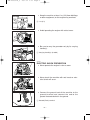
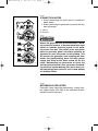
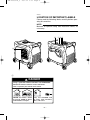
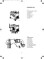
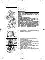
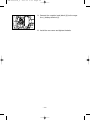
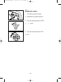
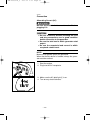
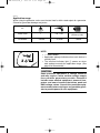
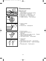
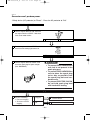
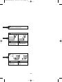
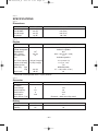
7XF-28199-10_hyoshi
08.1.25 9:33 AM
Page 1
Generator
OWNER’S MANUAL
EF4500iSE
PRINTED ON RECYCLED PAPER
PRINTED IN JAPAN
2008 9 02 – 1.0 × 1 !
PLEASE READ AND UNDERSTAND THIS MANUAL
COMPLETELY BEFORE OPERATING THE MACHINE.
LIT-19626-01-46
7XF-28199-10
7XF-28199-10_hyoshi
08.1.25 9:33 AM
Page 2
7XF-28199-10_a
08.1.31 9:19
Page A-1
AE00002
INTRODUCTION
Congratulations on your purchase of your new Yamaha.
This manual will provide you with a good basic understanding of the operation and
maintenance of this machine.
If you have any questions regarding the operation or maintenance of your machine,
please consult a Yamaha dealer.
AE00022
EF4500iSE
OWNER’S MANUAL
© 2008 by Yamaha Motor Corporation, U.S.A.
1st Edition, February 2008
All rights reserved.
Any reprinting or unauthorized use
without the written permission of
Yamaha Motor Corporation, U.S.A.
is expressly prohibited.
Printed in Japan
P/N LIT-19626-01-46
7XF-28199-10_a
08.1.31 9:19
Page A-2
IMPOTANT MANUAL INFORMATION
Particularly important information is distinguished in this manual by the following
notations.
The Safety Alert Symbol means ATTENTION! BECOME ALERT! YOUR SAFETY
IS INVOLVED!
w
Failure to follow WARNING instructions
could result in severe injury or death to
the engine operator, a bystander or a person inspecting or repairing the engine.
cC
A CAUTION indicates special precautions
that must be taken to avoid damage to the
engine.
NOTE:
A NOTE provides key information to make
procedures easier or clearer.
AE00032
w
PLEASE READ AND UNDERSTAND
THIS MANUAL COMPLETELY BEFORE
OPERATING THE MACHINE.
NOTE:
9 Yamaha continually seeks advancements in product design and quality.
Therefore, while this manual contains
the most current product information
available at the time of printing, there
may be minor discrepancies between
your engine and this manual. If there
is any question concerning this manual, please consult a Yamaha dealer.
9 This manual should be considered a
permanent part of this engine and
should remain with this engine when
resold.
* Product and specifications are subject to
change without notice.
7XF-28199-10_a
08.1.31 9:19
Page A-3
AE00041
CONTENTS
SAFETY INFORMATION ........................1
EXHAUST FUMES ARE
POISONOUS........................................1
FUEL IS HIGHLY FLAMMABLE AND
Stopping the engine............................18
Connection .........................................19
Application range................................20
PERIODIC MAINTENANCE ..................21
POISONOUS........................................1
Maintenance chart ..............................21
ENGINE AND MUFFLER MAY BE
Spark plug inspection .........................23
HOT ......................................................1
Carburetor adjustment........................24
ELECTRIC SHOCK PREVENTION......2
Engine oil replacement .......................24
CONNECTION NOTES ........................3
Air filter ...............................................25
CONNECTION .....................................3
Muffler screen and spark arrester.......27
EXTENSION CORD NOTES................3
Fuel tank filter .....................................29
LOCATION OF IMPORTANT
Battery ................................................30
LABELS...................................................4
Recommended battery .......................30
DESCRIPTION ........................................6
Fuse replacement...............................31
Control Panel........................................6
STORAGE .............................................32
CONTROL FUNCTION............................7
Drain the fuel ......................................32
Engine switch .......................................7
Engine ................................................32
Oil warning light (red) ...........................7
Battery ................................................33
AC protector .........................................8
Engine won’t start ...............................34
Hour meter............................................8
TROUBLESHOOTING ..........................35
Power meter .........................................8
Generator won’t produce power .........35
AC pilot light (green).............................8
SPECIFICATIONS.................................37
Overload indicator light.........................9
Dimensions.........................................37
Fuel tank cap ........................................9
Engine ................................................37
Fuel cock knob ...................................10
Generator ...........................................37
Ground (Earth) terminal......................10
Battery ................................................37
PREPARATION.....................................11
CONSUMER INFORMATION................38
Fuel.....................................................11
Identification number records .............38
Engine oil............................................12
Battery preparation .............................13
PRE-OPERATION CHECK ...................15
Pre-operation check ...........................15
Machine identification .........................38
LIMITED WARRANTY (EF- AND
EDL-SERIES) ........................................39
EXHAUST EMISSION CONTROL
OPERATION..........................................16
SYSTEM AND COMPONENTS .........41
Starting the engine .............................16
WIRING DIAGRAM ...............................43
7XF-28199-10_a
08.1.31 9:19
Page 1
AE00071
SAFETY INFORMATION
AE00072
EXHAUST FUMES ARE POISONOUS
741-7XFa
9 Never operate the engine in a closed area or it
may cause unconsciousness and death within a
short time. Operate the engine in a well ventilated
area.
AE00075
FUEL IS HIGHLY FLAMMABLE AND
POISONOUS
741-7XFb
741-7XFc
9 Always turn off the engine when refuelling.
9 Never refuel while smoking or in the vicinity of an
open flame.
9 Take care not to spill any fuel on the engine or
muffler when refuelling.
9 If you swallow any fuel, inhale fuel vapor, or allow
any to get in your eye(s), see your doctor immediately. If any fuel spills on your skin or clothing,
immediately wash with soap and water and
change your clothes.
9 When operating or transporting the machine, be
sure it is kept upright. If it tilts, fuel may leak from
the carburetor or fuel tank.
741-7XFd
AE00843
ENGINE AND MUFFLER MAY BE HOT
9 Place the machine in a place where pedestrians
or children are not likely to touch the machine.
741-7XFe
9 Avoid placing any flammable materials near the
exhaust outlet during operation.
741-7XFf
–1–
7XF-28199-10_a
08.1.31 9:19
Page 2
9 Keep the machine at least 1 m (3 ft) from buildings
or other equipment, or the engine may overheat.
a
a 1 m (3 ft)
741-7XFg
9 Avoid operating the engine with a dust cover.
741-7XFh
9 Be sure to carry the generator only by its carrying
handle(s).
1
1 Carrying handle(s) (shaded)
794-7XFa
AE00083
ELECTRIC SHOCK PREVENTION
9 Never operate the engine in rain or snow.
741-7XFi
9 Never touch the machine with wet hands or electrical shock will occur.
741-7XFj
9 Connect the ground lead of the machine to the
ground terminal and connect the end to the
ground electrode buried in the ground.
1
1 Ground (Earth) terminal
763-7XFa
–2–
7XF-28199-10_a
08.1.31 9:19
Page 3
AE00088
CONNECTION NOTES
1
9 Avoid connecting the generator to commercial
power outlet.
9 Avoid connecting the generator in parallel with any
other generator.
2
1 Correct
2 Incorrect
AE00091
CONNECTION
w
1
2
741-7XFk
Before the generator can be connected to a building’s electrical system, a licensed electrician must
install an isolation (transfer) switch in the building’s main fuse box. The switch is the connection
point for generator power and allows selection of
generator or main line power to the building. This
will prevent the generator from charging the main
power line (backfeeding) when the main power
supply has failed or has been turned off for line
repair. Backfeeding can electrocute or injure line
maintenance personnel. Also, generator and building electrical system damage can occur when normal operating power returns if unit is used without
an isolation switch.
AE00086
EXTENSION CORD NOTES
Extension cords should be protected by a tough flexible rubber sheath (IEC 245) or the equivalent to withstand mechanical stresses.
–3–
7XF-28199-10_a
08.1.31 9:19
Page 4
AE00062
LOCATION OF IMPORTANT LABELS
Please read the following labels carefully before operating this machine.
NOTE:
Maintain or replace safety and instruction labels, as
necessary.
2
3
5
1
DANGER
Using a generator indoors CAN KILL YOU IN MINUTES.
Generator exhaust contains carbon monoxide.
This is a poison you cannot see or smell.
NEVER use inside a home
or garage, EVEN IF doors
and windows are open.
Only use OUTSIDE and
far away from windows,
door, and vents.
–4–
1 64
7XF-28199-10_a
08.1.31 9:19
Page 5
2
q AVERTISSEMENT
q WARNING
8
8
8
8
8
8
8
READ THE OWNER‘S MANUAL AND ALL LABELS BEFORE OPERATING.
ONLY OPERATE IN WELL-VENTILATED AREAS.
EXHAUST GAS CONTAINS POISONOUS CARBON MONOXIDE.
CHECK FOR SPILLED FUEL OR FUEL LEAKS.
STOP ENGINE BEFORE REFUELING.
DO NOT OPERATE NEAR FLAMMABLE MATERIALS.
ELECTROCUTION CAN OCCUR IF GENERATOR IS USED IN RAIN,
SNOW, OR NEAR WATER. KEEP THIS UNIT DRY AT ALL TIMES.
8
8
8
8
8
LISEZ LE MODE D‘EMPLOI ET TOUTES LES ETIQUETTES AVANT DE
FAIRE FONCTIONNER LA MACHINE.
FAITES FONCTIONNER UNIQUEMENT DANS DES LIEUX BIEN AERES.
LES GAZ D‘ECHAPPEMENT CONTIENNENT DU MONOXYDE DE CARBONE.
VERIFIEZ SI DU CARBURANT A ETE RENVERSE DU S‘IL FUIT.
ARRETEZ LE MOTEUR AVANT DE FAIRE LE PLEIN DE CARBURANT.
N‘UTILISEZ PAS A PROXIMITE DE MATERIAUX INFLAMMABLES.
IL Y A RISQUE D‘ELECTROCUTION SI LE GENERATEUR FONCTIONNE
SOUS LA PLUIE, DANS LA NEIGE, OU PRES DE L‘EAU. GARDEZ LA
MACHINE AU SEC EN TOUTES CIRCONSTANCES.
7CF-24162-10
3
5
OIL
HOT EXHAUST
7WL-28176-10
zzzzzz
4
AC output
Rated
q CAUTION
zzHz
zzzzVA
zzzV
Use the specified spark plug only.
Phase
Fuel
Specified plug:BPR4ES(NGK)
Single
Gasoline
YAMAHA MOTOR POWERED PRODUCTS CO.,LTD.
MADE IN JAPAN
7XF-24164-10
6
Important Emissions Information
The air index of this engine is 3
(California only)
YAMAHA MOTOR POWERED PRODUCTS CO.,LTD.
This engine meets **** California exhaust and evaporative
emission regulations for small off-road engines.
This engine conforms to Phase 2 U.S.EPA regulations for
small nonroad engines.
EMISSIONS COMPLIANCE PERIOD : CATEGORY A(EPA)
EF: *YMXS.3572EA
DISPLACEMENT: 357cc
EVAP F: CMYMX23A
EMISSION CONTROL SYSTEM: EM
This engine is certified to operate on unleaded gasoline.
ENGINE OIL: SAE10W-30 TYPE: SE
No other adjustments needed.
–5–
0
2
4
6
8
10
MOST CLEAN
LEAST CLEAN
Note: The lower the air index, the less the pollution.
This engine is certified to be emissions compliant
for the following use:
INTERMEDIATE
MODERATE
X
(500 HOURS)
(250 HOURS)
Check owner's manual for further details.
EXTENDED
(1000 HOURS)
7XF-28199-10_a
08.1.31 9:19
Page 6
DESCRIPTION
1
23
AE00102
1
1
2
3
4
5
6
7
8
Carrying handles (shaded)
Fuel tank cap
Fuel gauge
Muffler
Caster lock lever
Oil filler cap
Oil drain plug
Battery
793-7XFa
4
8 76
5
793-7XFb
AE00103
Control panel
1 2
3
4
5
6
0 9 8
7
793-7XF
–6–
1
2
3
4
5
6
7
8
9
0
Hour meter
Power meter
AC protector
AC receptacle
Engine switch
Fuel cock knob
Ground (Earth) terminal
Overload indicator light
AC pilot light
Oil warning light
7XF-28199-10_a
08.1.31 9:19
Page 7
AE00101
CONTROL FUNCTION
q
w
e
AE00121
Engine switch
The engine switch controls the ignition system.
763-119
1
7 “ON”
Ignition circuit is switched on.
The engine can be started.
2
5 “STOP”
Ignition circuit is switched off.
The engine will not run.
3
6 “START”
Starting circuit is switched on.
The starter motor starts and the engine can be started.
After starting the engine, take your hand off the switch
immediately.
AE00111
Oil warning light (red)
When the oil level falls below the lower level, the oil
warning light comes on and then the engine stops
automatically. Unless you refill with oil, the engine will
not start again.
NOTE:
If the engine stalls or does not start, turn the engine
switch to “START” position. If the oil warning light
comes on, the engine oil is insufficient. Add oil and
restart.
700-7XF
–7–
7XF-28199-10_a
08.1.31 9:19
Page 8
AE00134
AC protector
1
The AC protector 1 trips when total amount of the two
receptable 2 loads exceeds 20A.
Press the switch to reset the AC protector.
2
793-7XFe
1
2
I “Set”
3 “Reset”
2
1
763-238a
1
Hour meter
The hour meter 1 shows the total number of hours
the generator has been run.
763-7XFf
Power meter
1
763-7XFg
1
The power meter 1 shows the amount of electric current used by a barmeter.
The generator output is normal when the segments of
the barmeter appear.
NOTE:
When 10 segments appear, the generator has almost
reached its rated output.
AC pilot light (green)
The AC pilot light 1 comes on when the engine starts
and produces power.
763-7XFc
–8–
7XF-28199-10_a
08.1.31 9:19
Page 9
AE01087
1
Overload indicator light
763-7XFd
The overload indicator light 1 comes on when an
overload of a connected electrical device is detected,
the inverter control unit overheats, or the AC output
voltage rises. Then, the AC protector will trip, stopping
power generation in order to protect the generator and
any connected electric devices. The AC pilot light
(green) will go off and the overload indicator light (red)
will stay on, but the engine will not stop running.
When the overload indicator light comes on and power
generation stops, proceed as follows:
1. Turn off any connected electric devices and stop
the engine.
2. Reduce the total wattage of connected electric
devices within the rated output.
3. Check for blockages in the cooling air inlet and
around the control unit. If any blockages are
found, remove.
4. After checking, restart the engine.
NOTE:
The overload indicator light may come on for a few
seconds at first when using electric devices that
require a large starting current, such as a compressor
or a submergible pump. However, this is not a malfunction.
Fuel tank cap
Remove the fuel tank cap by turning it counterclockwise.
707-7XFb
–9–
7XF-28199-10_a
08.1.31 9:19
Page 10
Fuel cock knob
The fuel cock supplies fuel from the fuel tank to the
carburetor.
The fuel cock has two positions.
763-7XFb
ON
With the knob in this position, fuel flows to the carburetor. Normal using is done with the knob in this position.
ON
OFF
With the knob in this position, fuel will not flow. Always
turn the knob to this position when the engine is not
running.
OFF
705-073c
Ground (Earth) terminal
1
It is a terminal which connects the earth line for prevention of electric shock.
When the electric device is earthed, always the generator must be earthed.
763-7XFa
1 Ground (Earth) terminal
Caster lock lever
The caster lock lever stops moving the generator.
1
2
1 “Release”
2 “Lock”
788-7XFh
– 10 –
7XF-28199-10_a
08.1.31 9:19
Page 11
PREPARATION
AE00856
Fuel
w
741-7XFl
707-7XFc
707-7XFa
9 Fuel is highly flammable and poisonous.
Check “SAFETY INFORMATION” (See page 1)
carefully before filling.
9 Do not overfill the fuel tank, otherwise it may
overflow when the fuel warms up and
expands.
9 After fill the fuel, make sure the fuel tank cap is
tightened securely.
cC
9 Immediately wipe off spilled fuel with a clean,
dry, soft cloth, since fuel may deteriorate
painted surfaces or plastic parts.
9 Use only unleaded gasoline. The use of leaded
gasoline will cause severe damage to internal
engine parts.
Make sure there is sufficient fuel in the tank.
When refueling, be sure to fill the tank to the bottom
edge of the fuel filter 4.
2
1
707-7XF
3
4
1 Fuel level gauge
2 Red line
“F”
Red line 2
Full
Empty
3 Fuel level
Recommended fuel:
Unleaded gasoline
Fuel tank capacity:
Total:
17.0 L (3.17 US gal, 2.64 Imp gal)
Your Yamaha engine has been designed to use regular unleaded gasoline with a pump octane number ((R
+ M)/2) of 86 or higher, or research octane number of
91 or higher.
– 11 –
7XF-28199-10_a
08.1.31 9:19
Page 12
AE00222
Engine oil
2
1
cC
The generator has been shipped without engine
oil. Do not start the engine before filling with the
sufficient engine oil.
788-7XFb
3
700-7XFa
1. Place the generator on a level surface.
2. Remove the bolts 1, and then pull outward on the
areas of rear cover 2 shown.
3. Remove the oil filler cap 3.
4. Fill the specified amount of the recommended
engine oil, and then install and tighten the oil filler
cap.
4 Upper level
r
700-103c
Recommended engine oil:
å YAMALUBE 4 (10W-30 or 10W-40),
SAE 10W-30 or 10W-40
∫ SAE #30
ç SAE #20
∂ SAE 10W
Recommended engine oil grade:
API Service SE type or higher
Engine oil quantity:
1.3 L (1.14 US qt, 1.37 lmp qt)
700-006
0°C
25°C
å YAMALUBE 4 (10W-30 or 10W-40)
∂ SAE 10W
ç SAE #20
32°F
∫ SAE #30
80°F
5. Install the rear cover and tighten the bolts.
– 12 –
7XF-28199-10_a
08.1.31 9:19
Page 13
AE01083
Battery preparation
(See page 30)
w
Battery electrolyte is poisonous and dangerous,
causing severe burns, etc. It contains sulfuric (sulphuric) acid. Avoid contact with skin, EYES or
clothing.
Antidote:
EXTERNAL-Flush with water.
INTERNAL-Drink large quantities of water or milk.
Follow with milk of magnesia, beaten egg or vegetable oil. Call physician immediately.
Eyes: Flush with water for 15 minutes and get
prompt medical attention. Batteries produce explosive gases. Keep sparks, flame, cigarettes, etc.
away. Ventilate when charging or using in closed
space. Always cover eyes when working near batteries. KEEP OUT OF REACH OF CHILDREN.
762-012
1. Remove the bolts 1, and then pull outward on the
areas of rear cover 2 shown.
2
1
788-7XFb
3
4
5
762-7XFa
7
6
2. Remove the wing nuts 3 and battery plate 4.
3. Remove the battery 5.
4. Fill the battery with the electrolyte.
Refer to the instruction sheet included with the
electrolyte for filling instructions.
5. Turn the engine switch to the “STOP” position to
prevent accidental short circuiting.
6. Connect the positive lead (red) 6 to the positive
(+) battery terminal 7.
7. Install the battery 5 onto the tray.
8. Install the battery plate 4 and tighten the wing
nuts 3.
762-7XFc
– 13 –
7XF-28199-10_a
08.1.31 9:19
Page 14
9. Connect the negative lead (black) 8 to the negative (-) battery terminal 9.
8
9
762-7XFd
10. Install the rear cover and tighten the bolts.
– 14 –
7XF-28199-10_a
08.1.31 9:19
Page 15
AE00845
PRE-OPERATION CHECK
w
If any item in the Pre-operation check is not working properly, have it inspected and repaired before
operating the generator.
The condition of a generator is the owner's responsibility. Vital components can start to deteriorate quickly
and unexpectedly, even if the generator unused.
NOTE:
Pre-operation checks should be made each time the
generator is used.
Pre-operation check
Fuel (See page 11)
9 Check fuel level in fuel tank.
9 Refuel if necessary.
Fuel line
9 Check fuel hose for crack or damage.
9 Replace if necessary.
Engine oil (See page 12)
9 Check oil level in engine.
9 If necessary, add recommended oil to specified
level.
9 Check generator for oil leakage.
The point where abnormality was recognized by
use.
9 Check operation.
9 If necessary, consult a Yamaha dealer.
– 15 –
7XF-28199-10_a
08.1.31 9:19
Page 16
AE00846
OPERATION
w
761-7XFb
9 Never operate the engine in a closed area or it
may cause unconsciousness and death within
a short time. Operate the engine in a well ventilated area.
9 Before starting the engine, do not connect any
electric devices.
cC
The generator has been shipped without engine
oil. Do not start the engine till fill with the sufficient engine oil.
AE00918
q
ON
Starting the engine
1. Turn the fuel cock knob to “ON”.
1 “ON”
OFF
705-073
2. Turn the engine switch to “ON”.
1
1
7 “ON”
763-127h
– 16 –
7XF-28199-10_a
08.1.31 9:19
q
Page 17
3. Turn the engine switch to “START”.
Take your hand off the switch immediately after
the engine starts.
1
763-120a
6 “START”
cC
If the engine fails to start, release the switch, wait
a few seconds, then try again. Each attempt
should be as short as possible to preserve the battery. Do not crank the engine more than 5 seconds
on any one attempt.
– 17 –
7XF-28199-10_a
08.1.31 9:19
Page 18
AE00840
Stopping the engine
1. Turn off any electric devices.
2. Disconnect any electric devices.
761-7XFb
3. Turn the engine switch to “STOP”.
q
1
5 “STOP”
763-120b
4. Turn the fuel cock knob to “OFF”.
ON
1 “OFF”
q OFF
705-073a
– 18 –
7XF-28199-10_a
08.1.31 9:19
Page 19
AE00839
Connection
Alternating Current (AC)
w
Be sure any electric devices are turned off before
plugging it in.
cC
9 Be sure all electric devices including the lines
and plug connections are in good condition
before connection to the generator.
9 Be sure the total load is within generator rated
output.
9 Be sure the receptacle load current is within
receptacle rated current.
NOTE:
Make sure to ground (earth) the generator.
When the electric device is earthed, always the generator must be earthed.
1. Start the engine.
2. Plug in to the AC receptacle.
761-7XFa
3. Make sure the AC pilot light 1 is on.
4. Turn on any electric devises.
1
763-7XFc
– 19 –
7XF-28199-10_a
08.1.31 9:19
Page 20
AE00812
Application range
When using the generator, make sure the total load is within rated output of a generator.
Otherwise, generator damage may occur.
AC
Power factor
1
0.8 ~ 0.95
0.4 ~ 0.75
(Efficiency 0.85)
EF4500iSE
– 4,000W
– 3,200W
– 1,360W
1
763-7XFd
NOTE:
9 “–” means below.
9 Application wattage indicates when each device is
used by itself.
9 The overload indicator light 1 comes on when
total wattage exceeds the application range. (See
page 9 for more details.)
cC
Some precision equipment is voltage sensitive
and may require a more uniform voltage supply
than portable generators provide. Examples
include some medical equipment, personal computers, and some inverters that sense peak and
RMS voltage values. Consult the precision-equipment vendor before relying on any portable generator to provide power to such equipment.
– 20 –
7XF-28199-10_a
08.1.31 9:19
Page 21
AE00401
PERIODIC MAINTENANCE
Safety is an obligation of the owner. Periodic inspection, adjustment and lubrication will
keep your generator in the safest and most efficient condition possible. The most important points of generator inspection, adjustment, and lubrication are explained on the following pages.
w
If you are not familiar with maintenance work, have a Yamaha dealer do it for you.
AE00403
Maintenance chart
w
Stop the engine before starting maintenance work.
cC
Use only Yamaha specified genuine parts for replacement. Ask an authorized
Yamaha dealer for further attention.
Item
Spark plug
Routine
• Check condition.
• Check fuel level and leakage.
Fuel hose
• Check fuel hose for cracks or damage.
Replace if necessary.
Air filter element
Muffler screen
Spark arrester
1
• Clean and replace if necessary.
Fuel
Engine oil
Every
Preoperation 6 months 12 months
check
or 100 Hr or 300 Hr
• Check oil level in engine.
1
1
1
1(*1)
• Replace
• Check condition.
1(*2)
• Clean
• Check condition.
• Clean and replace if necessary.
• Check condition.
• Clean and replace if necessary.
1
1
Fuel filter
• Clean and replace if necessary.
1
Fuel strainer
• Clean and replace if necessary
1
– 21 –
7XF-28199-10_a
08.1.31 9:19
Item
Crankcase breather
hose
Cylinder head
Valve clearance
Fittings / fasteners
Page 22
Routine
Every
Preoperation 6 months 12 months
check
or 100 Hr or 300 Hr
• Check breather hose for cracks or
damage.
1
• Replace if necessary.
• Decarbonize cylinder head.
★
• More frequently if necessary.
★
• Check and adjust when engine is cold.
• Check all fittings and fasteners.
★
• Correct if necessary.
The point where abnormality was recognized by use.
1
*1·····Initial replacement of the engine oil is after one month or 20 hours of operation.
*2·····The air filter element needs to be cleaned more frequently when using in unusually wet or dusty areas.
★····· Since these items require special tools, data and technical skills, have a Yamaha dealer perform the service.
– 22 –
7XF-28199-10_b
08.1.31 9:21
Page 23
AE01051
Spark plug inspection
2
1
The spark plug is important engine components, which
should be checked periodically.
1. Remove the bolts 1, and then pull outward on the
areas of front cover 2 shown.
788-7XFa
2. Remove the spark plug cap and then remove the
spark plug.
3. Check for discoloration and remove the carbon.
The porcelain insulator around the center electrode of spark plug should be a medium-to-light
tan color.
760-7XF
4. Check the spark plug type and gap a.
Standard Spark Plug:
BPR4ES (NGK)
Spark Plug Gap:
0.7–0.8 mm (0.028–0.031 in)
a
760-001a
NOTE:
The spark plug gap should be measured with a wire
thickness gauge and, if necessary, adjusted to specification.
5. Install the spark plug.
Spark Plug Torque:
20.0 N•m (2.00 kgf•m, 14.8 lbf•ft)
NOTE:
If a torque wrench is not available when installing a
spark plug, a good estimate of the correct torque is
1/4-1/2 turn past finger tight. However, the spark plug
should be tightened to the specified torque as soon as
possible.
6. Install the spark plug cap.
7. Install the front cover and tighten the bolts.
– 23 –
7XF-28199-10_b
08.1.31 9:21
Page 24
AE00431
Carburetor adjustment
The carburetor is a vital part of the engine. Adjusting
should be left to a Yamaha dealer with the professional knowledge, specialized data, and equipment to do
so properly.
AE00412
Engine oil replacement
w
Avoid draining the engine oil immediately after
stopping the engine. The oil is hot and should be
handled with care to avoid burns.
2
1
1. Place the machine on a level surface and warm
up the engine for several minutes.
Then stop the engine.
2. Remove the bolts 1, and then pull outward on the
areas of rear cover 2 shown.
788-7XFb
8
5
6
7
4
3
700-7XFb
3. Remove the rubber cap 3, plastic plug 4 and the
oil filler cap 5.
4. Place an oil pan under the engine. Remove the oil
drain bolt 6 so that the oil can be completely
drained.
5. Check the drain bolt, gasket 7, oil filler cap and
O-ring 8.
If damaged, replace.
6. Reinstall the oil drain bolt.
Drain bolt Torque:
30.0 N•m (3.1 kgf•m, 22.2 lbf•ft)
– 24 –
7XF-28199-10_b
08.1.31 9:21
Page 25
7. Add engine oil to the upper level 1.
q
700-006a
0°C
25°C
å YAMALUBE 4 (10W-30 or 10W-40)
∂ SAE 10W
ç SAE #20
32°F
∫ SAE #30
Recommended engine oil:
å YAMALUBE 4 (10W-30 or 10W-40),
SAE 10W-30 or 10W-40
∫ SAE #30
ç SAE #20
∂ SAE 10W
Recommended engine oil grade:
API Service SE type or higher
Engine oil quantity:
1.3 L (1.14 lmp qt, 1.37 US qt)
80°F
cC
Be sure no foreign material enters the crankcase.
8. Install the oil filler cap, the rubber cap and the
plastic plug.
9. Install the front cover and tighten the bolts.
AE01084
Air filter
2
1
1. Remove the bolts 1, and then pull outward on the
areas of front cover 2 shown.
788-7XFa
2. Remove the bolts 3.
3
3
788-7XFi
– 25 –
7XF-28199-10_b
08.1.31 9:21
1
Page 26
3. Remove the air filter cover 1 and foam element
2.
4. Wash the foam element in solvent and dry it.
5. Oil the foam element and squeeze out excess oil.
The foam element should be wet but not dripping.
2
Recommended oil:
Foam-air-filter oil
or
SAE #20 motor oil
cC
Do not wring out the foam element when squeezing it.
This could cause it to tear.
6. Insert the foam element into the air filter case.
710-037a
NOTE:
Be sure the foam element sealing surface matches the
air filter so there is no air leak.
cC
The engine should never run without the foam element; excessive piston and cylinder wear may
result.
7. Install the air filter cover in its original position and
tighten the bolts.
8. Install the front cover and tighten the bolts.
– 26 –
7XF-28199-10_b
08.1.31 9:21
Page 27
AE01075
Muffler screen and spark arrester
w
741-7XFl
2
1
The engine and muffler will be very hot after the
engine has been run.
Avoid touching the engine and muffler while they
are still hot with any part of your body or clothing
during inspection or repair.
1. Remove the bolts 1, and then pull outward on the
areas of rear cover 2 shown.
788-7XFb
2
2. Loosen the screw 1 and then remove the muffler
cap 2, the muffler screen 3 and spark arrester
4.
1
3
711-7XFa
711-7XFb
4
711-7XFc
– 27 –
7XF-28199-10_b
08.1.31 9:21
Page 28
3. Remove the carbon deposits on the muffler
screen and spark arrester using a wire brush.
cC
711-075
When cleaning, use the wire brush lightly to avoid
damaging or scratching of the muffler screen and
spark arrester.
4. Check the muffler screen and spark arrester.
Replace them if damaged.
5. Install the spark arrester.
2
NOTE:
Align the spark arrester projection 1 with the hole 2
in the muffler pipe.
1
711-7XFd
6. Install the muffler screen and the muffler cap.
7. Install the rear cover and tighten the bolts.
711-7XFe
– 28 –
7XF-28199-10_b
08.1.31 9:21
Page 29
AE00471
Fuel tank filter
q
w
Never use or be near fuel and solvent while smoking or in the vicinity of an open flame.
1. Remove the fuel tank cap and filter 1.
2. Clean the filter with gasoline.
If damaged, replace it.
3. Wipe the filter and install it.
4. Install the fuel tank cap.
w
Be sure the fuel tank cap is tightened securely.
707-043b
– 29 –
7XF-28199-10_b
08.1.31 9:21
Page 30
AE00842
Battery
This generator is equipped with a sealed type (MF)
battery, which does not require any maintenance.
There is no need to check the electrolyte or to add distilled water.
w
762-012
Battery electrolyte is poisonous and dangerous,
causing severe burns, etc. It contains sulfuric (sulphuric) acid. Avoid contact with skin, EYES or
clothing.
Antidote:
EXTERNAL-Flush with water.
INTERNAL-Drink large quantities of water or milk.
Follow with milk of magnesia, beaten egg or vegetable oil. Call physician immediately.
Eyes: Flush with water for 15 minutes and get
prompt medical attention. Batteries produce explosive gases. Keep sparks, flame, cigarettes, etc.
away. Ventilate when charging or using in closed
space. Always cover eyes when working near batteries. KEEP OUT OF REACH OF CHILDREN.
To charge the battery
Have a Yamaha dealer charge the battery as soon as
possible if it seems to have discharged.
AE01057
Recommended battery
Recommended battery:
Capacity: 12V/18A•h
– 30 –
7XF-28199-10_b
08.1.31 9:21
Page 31
AE01077
Fuse replacement
w
Be sure to use specified fuse. A wrong fuse will
cause electrical system damage and A FIRE HAZARD.
cC
2
Be sure the engine switch is turned to “STOP” to
prevent accidental short circuiting.
1
788-7XFa
1. Remove the bolts 1, and then pull outward on the
areas of front cover 2 shown.
2. Replace the fuse with one of proper amperage.
Specified fuse: 20A
779-7XF
NOTE:
If the fuse immediately blows again, consult a Yamaha
dealer.
3. Install the front cover and tighten the bolts.
– 31 –
7XF-28199-10_b
08.1.31 9:21
Page 32
AE00601
STORAGE
Long term storage of your machine will require some
preventive procedures to guard against deterioration.
AE01056
Drain the fuel
1. Remove the fuel tank cap. Extract the fuel from
the fuel tank into an approved gasoline container
using a commercially available hand siphon.
Then, install the fuel tank cap.
1
707-7XFd
w
Fuel is highly flammable and poisonous. Check
“SAFETY INFORMATION” (See page 1) carefully.
cC
Immediately wipe off spilled fuel with a clean, dry,
soft cloth, since fuel may deteriorate painted surfaces or plastic parts.
2. Turn the fuel cock knob to “OFF”.
3. Drain the fuel from the carburetor by loosening the
drain screw 1 on the carburetor float chamber.
4. Start the engine and leave it run until it stops.
This will burn any remaining fuel in the carburetor.
AE00889
Engine
712-7XF
788-7XFg
Perform the following steps to protect the cylinder, piston ring, etc. from corrosion.
1. Remove the spark plug cap and spark plug, pour
about one tablespoon of SAE 10W30 or 20W40
motor oil into spark plug hole and reinstall the
spark plug only.
2. Turn the engine switch to “START” and crank the
engine several seconds with ignition off to coat the
cylinder walls with oil.
3. Clean exterior of the generator and apply a rust
inhibitor.
4. Store the generator in a dry, well-ventilated place,
with the cover placed over it.
5. The generator must remain in a vertical position
when stored, carried or operated. The caster lock
lever shold be in the “Lock” when stored or operated.
– 32 –
7XF-28199-10_b
08.1.31 9:21
Page 33
AE01086
Battery
1. Remove the battery.
2. Store the battery in a cool, dark and dry place and
charge it once a month.
762-003
Do not store the battery in an excessively warm or
cold place [i.e., less than 0°C (30°F) or more than
30°C (90°F)].
w
9 Disconnect the negative lead (black) first, then
the positive lead (red) from the battery.
9 Connect the positive lead (red) first, then the
negative lead (black) to the battery when
installing the battery.
– 33 –
7XF-28199-10_b
08.1.31 9:21
Page 34
AE00512
TROUBLESHOOTING
707-7XFc
ON
Engine won’t start
1. Fuel systems
No fuel supplied to combustion chamber.
2 No fuel in tank .... Supply fuel.
2 Fuel in tank .... Fuel cock knob to “ON”.
2 Clogged fuel line .... Clean fuel line.
2 Clogged carburetor .... Clean carburetor.
OFF
705-073c
2. Engine oil system
Insufficient
2 Oil level is low .... Add engine oil.
700-006
3. Electrical systems
2 Engine switch to “START” 1.
Poor spark
2 Spark plug dirty with carbon or wet .... Remove
carbon or wipe spark plug dry.
2 Faulty ignition system .... Consult dealer.
q
763-120a
4. Compression
Insufficient
2 Worn out piston and cylinder .... Consult dealer.
2 Loose cylinder head nuts .... Tighten nuts properly.
2 Damaged gasket .... Replace gasket.
760-009
– 34 –
7XF-28199-10_b
08.1.31 9:21
Page 35
AE00515
Generator won’t produce power
•Safety device (AC protector) to "Reset"····Press the AC protector to “Set”.
A
ENGINE DOES NOT START
B
Turn the engine switch to “ON”, then turn
the engine switch to “START”. And check
if the starter motor cranks.
F
L
C
Cranks
D
G
Does not come on H
Does not crank
Turn the engine switch to “START”, and
check if the oil warning light comes on.
Turn the engine switch to “START” and
check the spark plug for spark strength.
(See “WARNING”).
M
Engine does not start.
R
Check the following
9 Fuel cock clogging
9 Air cleaner element
clogging.
w
9 To prevent FIRE HAZARDS be
sure fuel is not present in the
spark plug area.
9 To prevent FIRE HAZARDS be
sure to place the spark plug
as far way as possible from
the spark plug hole and carburetor area.
9 To prevent ELECTRIC SHOCK
do not hold spark plug lead
with hand while testing.
N
S
Clogged
T
OK
Comes on
Engine starts.
– 35 –
U
Clean or Replace; Consult a
Yamaha dealer.
V
Consult a Yamaha dealer.
7XF-28199-10_b
E
08.1.31 9:21
Faulty battery and/or starter motor.
Consult a Yamaha dealer.
I
Check engine oil level.
J
OK
Consult a
Yamaha dealer.
O
P
Page 36
K
Level low
Add engine oil.
Check the spark plug.
9 Type:
9 Gap:
Incorrect
Replace or
Adjust Gap.
Q
OK
Clean the spark
plug.
– 36 –
7XF-28199-10_b
08.1.31 9:21
Page 37
AE00701
SPECIFICATIONS
AE00702
Dimensions
Overall Length
Overall Width
Overall Height
Dry Weight
Unit
mm (in)
mm (in)
mm (in)
kg (lb)
EF4500iSE
780 (30.7)
616 (24.3)
692 (27.2)
88 (194)
AE00704
Engine
Unit
EF4500iSE
Type
Cylinder Arrangement
3
Displacement
cm
Bore × Stroke
mm (in)
Operation Hours
Hr
Fuel
Fuel Tank Capacity L (US gal, Imp gal)
Engine Oil Quantity L (US qt, Imp qt)
Ignition System
Spark Plug: Type
Gap
mm (in)
Noise Level*
dB (A)
Air cooled 4-stroke gasoline OHV
Inclined, 1 cylinder
357
85.0 × 63.0 (3.35 × 2.48)
7.4
Unleaded gasoline
17.0 (4.49, 3.74)
1.3 (1.14, 1.37)
TCI
BPR4ES (NGK)
0.7 – 0.8 (0.028 – 0.031)
60
* : Measured at rated operation from 7 m (23 ft) distance.
AE00707
Generator
AC Output
Rated voltage
Rated frequency
Rated current
Rated output
Safety Device: Type
Unit
EF4500iSE
V
Hz
A
kVA
120
60
33.3
4.0
Electronic + Mechanical (By metal)
Unit
V
Ah
EF4500iSE
12
18
Battery
Voltage
Capacity
– 37 –
7XF-28199-10_b
08.1.31 9:21
Page 38
CONSUMER INFORMATION
AE00012
PRI-I.D. NUMBER:
Identification number records
Record your Primary I.D., and serial numbers in the spaces provided, to assist you
in ordering spare parts from a Yamaha
dealer.
Also record and keep these I.D. numbers
in a separate place in case your machine
is stolen.
MODEL
PRI-I.D.
CODE
SERIAL No.
AE00011
Machine identification
The machine serial number is stamped in
the location as shown.
Serial NO.
7XF –
7XF-24163-00
790-7XFb
NOTE:
The first three digits of these numbers are
for model identification; the remaining digits are the unit production number. Keep a
record of these numbers for reference
when ordering parts from a Yamaha dealer.
– 38 –
7XF-28199-10_b
08.1.31 9:21
Page 39
AE01119
YAMAHA MOTOR CORPORATION U.S.A.
EF- AND EDL-SERIES GENERATOR LIMITED WARRANTY
Yamaha Motor Corporation, U.S.A. hereby warrants that new Yamaha consumer generators purchased from an authorized Yamaha consumer
generator dealer in the continental United States
will be free from defects in material and workmanship for the period of time stated herein, subject to
certain stated limitations.
THE PERIOD OF WARRANTY Any new EFseries or EDL-series Yamaha Generator purchased for private, non-commercial use from an
authorized Yamaha consumer generator dealer in
the continental United States will
be warranted against defects in material or workmanship for a period two (2) years from date of
purchase, subject to exclusions noted herein. Any
Yamaha non-commercial
generator purchased and utilized for commercial
or rental applications will be warranted for a period
one (1) year from the date of purchase, subject to
exclusions noted herein.
DURING THE PERIOD OF WARRANTY any
authorized Yamaha consumer generator dealer
will, free of charge, repair or replace, at Yamaha’s
option, any part adjudged defective by Yamaha
due to faulty workmanship or material from the
factory. Parts used in warranty repairs will be warranted for the balance of the product’s warranty
period. All parts replaced under warranty become
property of Yamaha Motor Corporation U.S.A.
GENERAL EXCLUSIONS from this warranty shall
include any failures caused by:
a. Installation of parts or accessories that are not
qualitatively equivalent to genuine Yamaha
parts.
b. Abnormal strain, neglect, or abuse.
c. Lack of proper maintenance.
d. Accident or collision damage.
SPECIFIC EXCLUSIONS from this warranty shall
include parts replaced due to normal wear or routine maintenance.
2.
Give notice to an authorized Yamaha consumer generator dealer of any and all apparent defects within ten (10) days after discovery, and make the unit available at that time
for inspection and repairs at such dealer’s
place of business.
WARRANTY TRANSFER: To transfer the warranty from the original purchaser to any subsequent
purchaser(s), it is imperative that the unit be
inspected and registered for warranty by an authorized Yamaha consumer generator dealer. In order
for this warranty to remain in effect, this inspection
and registration must take place within ten (10)
days after transfer. An inspection and registration
fee will be charged for this service. In no case will
the warranty be extended beyond the original period.
YAMAHA MOTOR CORPORATION, U.S.A. MAKES
NO OTHER WARRANTY OF ANY KIND,
EXPRESSED OR IMPLIED. ALL IMPLIED WARRANTIES OF MERCHANTABILITY AND FITNESS
FOR A PARTICULAR PURPOSE WHICH EXCEED
THE OBLIGATIONS AND TIME LIMITS STATED IN
THIS WARRANTY ARE HEREBY DISCLAIMED BY
YAMAHA MOTOR CORPORATION, U.S.A. AND
EXCLUDED FROM THIS WARRANTY.
SOME STATES DO NOT ALLOW LIMITATIONS ON
HOW LONG AN IMPLIED WARRANTY LASTS, SO
THE ABOVE LIMITATION MAY NOT APPLY TO
YOU. ALSO EXCLUDED FROM THIS WARRANTY
ARE ANY INCIDENTAL OR CONSEQUENTIAL
DAMAGES INCLUDING LOSS OF USE. SOME
STATES DO NOT ALLOW THE EXCLUSION OR
LIMITATION OF INCIDENTAL OR CONSEQUENTIAL DAMAGES, SO THE ABOVE EXCLUSION
MAY NOT APPLY TO YOU.
THIS WARRANTY GIVES YOU SPECIFIC LEGAL
RIGHTS, AND YOU MAY ALSO HAVE OTHER
RIGHTS WHICH VARY FROM STATE TO STATE.
THE CUSTOMER’S RESPONSIBILITY under this
warranty shall be to:
1. Operate and maintain the generator as specified in the appropriate Owner’s Manual;
– 39 –
YAMAHA MOTOR CORPORATION, U.S.A.
Post Office Box 6555
Cypress, California 90630
7XF-28199-10_b
08.1.31 9:21
Page 40
WARRANTY QUESTIONS AND ANSWERS
Q. What costs are my responsibility during the
warranty period?
A. The customer’s responsibility includes all
costs of normal maintenance service, nonwarranty repairs, accident damages, as well
as oil and spark plugs.
Q. What are some examples of “abnormal” strain,
neglect, or abuse?
A. These terms are general and overlap each
other in areas. Specific examples include:
Running the machine out of oil; lack of proper
maintenance; operating the machine with a
broken or damaged part which causes another part to fail; and so on. If you have any
specific questions on operation or maintenance, please contact your dealer for advice.
Q. Does the warranty cover incidental costs such
as transportation due to a failure?
A. No. The warranty is limited to repair of the
machine itself.
Q. May I perform any or all of the recommended
maintenance shown in the Owner’s Manual
instead of having the dealer do them?
A. Yes, if you are a qualified mechanic and follow
the procedures specified in the Owner’s and
Service Manual. We do recommend, however,
that items requiring special tools or equipment
be done by a Yamaha generator dealer.
Q. Will the warranty be void or cancelled if I do
not operate or maintain my new Yamaha
exactly as specified in the Owner’s Manual?
A. No. The warranty on a new Yamaha cannot
be “voided” or “cancelled.”
However, if a particular failure is caused by
operation or maintenance other than as
shown in the Owner’s Manual, that failure
may not be covered under warranty.
Q. What responsibility does my dealer have
under this warranty?
A. Each Yamaha generator dealer is expected
to:
1. Check the operation of the generator
before sale.
2. Explain the operation, maintenance, and
warranty requirements to your satisfaction
at the time of sale, and upon your request
at any later date.
In addition, each Yamaha generator dealer is
held responsible for his setup, service and
warranty repair work.
Q. Is the warranty transferable to second owners?
A. Yes. The remainder of the existing warranty
can be transfered upon request.
The unit has to be inspected and reregistered
by an authorized Yamaha generator dealer for
the policy to remain effective.
CUSTOMER SERVICE
If your machine requires warranty service, you
must take it to any authorized Yamaha generator
dealer within the continental United States. Be
sure to bring your warranty registration identification or other valid proof of the original date of purchase. If a question or problem arises regarding
warranty, first contact the owner of the dealership.
Since all warranty matters are handled at the dealer level, this person is in the best position to help
you. If you are still not satisfied and require additional assistance, please write:
YAMAHA MOTOR CORPORATION U.S.A.
CUSTOMER RELATIONS DEPARTMENT
P.O. BOX 6555
Cypress, California 90630
CHANGE OF ADDRESS
The federal government requires each manufacturer to maintain a complete, up-to-date list of all
first purchasers against the possibility of a safetyrelated defect and recall. This list is compiled from
the purchase registrations sent to Yamaha Motor
Corporation, U.S.A. by the selling dealer at the
time of your purchase. If you should move after
you have purchased your new generator, please
advise us of your new address by sending a postcard listing your Yamaha model name, engine
number, dealer number (or dealer’s name) as it is
shown on your warranty identification, your name
and new mailing address. Mail to:
YAMAHA MOTOR CORPORATION, U.S.A.
WARRANTY DEPARTMENT
P.O. Box 6555
Cypress, California 90630
This will ensure that Yamaha Motor Corporation,
U.S.A. has an up-to-date registration record in
accordance with federal law.
– 40 –
7XF-28199-10_b
08.1.31 9:21
Page 41
AE00789
EXHAUST EMISSION CONTROL SYSTEM AND COMPONENTS
Item
Acronym
9 CARB. ASSY., LH. & JT., ......................CARB (Carburetor)
CARBURETOR2
9 T.C.I. MAGNETO ASSY. & .....................EI (Electronic Ignition)
PLUG, SPARK
9 CRANKCASE1 & HEAD, .......................PCV (Positive Crankcase
CYLINDER1
Ventilation)
9 AIR FILTER ASSY. .................................ACL (Air Cleaner)
9 MUFF., 2, CAP, NET, WIRE2 &
ARRESTER, SPARK
The above items and the corresponding acronyms are provided in accordance with U.S.
EPA REGULATIONS FOR NEW NONROAD SPARK-IGNITION NONHANDHELD
ENGINES and the CALIFORNIA REGULATIONS FOR 1995 AND LATER SMALL OFFROAD ENGINES.
The acronyms conform to the latest version of the SAE’s recommended practice document J1930, “Diagnostic Acronyms, Terms, and Definitions For Electrical/Electronic
System”.
It is recommended that these items be serviced by a Yamaha dealer.
– 41 –
7XF-28199-10_b
08.1.31 9:21
Page 42
— MEMO —
– 42 –
– 43 –
R
R
M
B
B/W Or G/R
B/W Or
p
i
o
B
d
W
a
L
L
L/Y
B/R
y
u
W G/R G/R W
s
L/W
L/R
L/Y B/R
g
G
Y
R
L
Or
G/W
Y/W
R/W
L/W
Or/W
Y
Y
Y
W
G/R
L/Y
B/R
L
G
Y
Or
R
L/W
G/W
Y/W
Or/W
R/W
Y
Y
Y
2
R
Br
R/W R/W
R/B R/B
G/Y G/Y
L/G
L/W
Y/W
R/L
G/Y
Y
B/W
R
Br
R
R
t
r
4
R G/Y
Br
R
3
Br
R
5
B/W
Y
G/R
L/W
G/Y
Y
W G/Y
R/B G/R
7
6
5
L
Y
B/W
Y
G/Y G/R G/R G/Y
L/W Y
Y L/W
L
B/W
Or
Y
G/Y
G/Y Or B/W B
R R/W R/W R
Y L/R
L/R Y
G/R R/B R/B
W
G/R
G/Y
R/B
Y/W
L/W
L/G
G/Y
R/L
G/R
Or
G/Y
R
R/W
L/R
R/B
Y
Y/W
L/W
L/G
G/Y
R/L
B/W
Y
G/Y
0
8
G/R
L/W
G/Y
Y
q
e
w
Y L/R R/B R/W R B/W B
G/Y
Y
L/R
R/B
R/W
R
B/W
B
OFF
ON
START
9
G/Y
G/Y
08.1.31 9:21
f
G
Y
R
L
Or
h
W
W
W
G/W
Y/W
R/W
L/W
Or/W
1
WIRING DIAGRAM
AE00751
7XF-28199-10_b
Page 43
1
2
3
4
5
6
7
8
9
0
q
w
e
r
t
y
u
i
o
p
a
s
d
f
g
h
Main coil
Control unit
AC protector (breaker)
AC pilot light
AC receptacle
Overload indicator light
Hour meter/power meter
Ground (Earth) terminal
Rectifier/regulator
Engine switch
Speed limiter assembly
Rectifier
Oil warning light
Diode assembly
Fuse
Oil level gauge
T.C.I magneto
Spark plug
T.C.I unit
Battery
Starter motor
Starter relay
Fuel cut sorenoid valve
Thermo sencer
Throttle motor
Auto choke
Color code
B
Black
Br
Brown
G
Green
L
Blue
Or
Orange
P
Pink
R
Red
W
White
Y
Yellow
Y/W Yellow/White
B/R
Black/Red
B/W Black/White
G/R Green/Red
G/W Green/White
G/Y Green/Yellow
L/G
Blue/Green
L/R
Blue/Red
L/W Blue/White
L/Y
Blue/Yellow
Or/W Orange/White
R/B
Red/Black
R/L
Red/Blue
R/W Red/White
7XF-28199-10_b
08.1.31 9:21
Page 44
– 44 –
7XF-28199-10_b
08.1.31 9:21
— MEMO —
Page 45
7XF-28199-10_hyoshi
08.1.25 9:33 AM
Page 2
7XF-28199-10_hyoshi
08.1.25 9:33 AM
Page 1
Generator
OWNER’S MANUAL
EF4500iSE
PRINTED ON RECYCLED PAPER
PRINTED IN JAPAN
2008 9 02 – 1.0 × 1 !
PLEASE READ AND UNDERSTAND THIS MANUAL
COMPLETELY BEFORE OPERATING THE MACHINE.
LIT-19626-01-46
7XF-28199-10