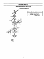
1
IMPORTANT
MANUAL
Do Not Throw Away
S _A/RS
Operator's
Manual
@
CRAFTSMAN"
Model No.
358.351141
358.351061
Always Wear Eye Protection
CUSTOMER
ASSISTANCE
1-800-235-5878
Mon,- Sat.7 a.m.- 7 p.m.
Sun. 10 a.m. - 7 p.m.
_b
READ
THE OPERATOR'S
ARNING:
MANUAL AND FOLLOW
ALL WARNINGS AND
SAFETY INSTRUCTIONS.
FAILURE TO DO SO CAN
RESULT IN SERIOUS
INJURY.
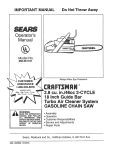
FTSMRN°
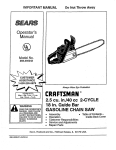
2.2 cu. in./36cc 2-CYCLE
14 Inch Guide Bar
16 Inch Guide Bar
GASOLINE CHAIN SAW
•
•
•
•
•
Assembly
Operation
Customer Responsibilities
Service and Adjustments
Repair Parts
Sears, Roebuck and Co., Hoffman Estates, IL 60179 U.S.A.
530-083950-1-07/19/95
SAFETY
RULES
WARNING:
ALWAYS DISCONNECT SPARK PLUG WIRE AND PLACE WIRE WHERE IT CANNOT CONTACT SPARK
PLUG TO PREVENT ACCIDENTAL STARTING WHEN SETTING UP, TRANSPORTING, ADJUSTING OR
MAKING REPAIRS EXCEPT CARBURETOR ADJUSTMENTS.
BECAUSE A CHAIN SAW IS A HIGH-SPEED WOOD-CUTTING
TOOL, SPECIAL SAFETY
PRECAUTIONS MUST BE OBSERVED TO REDUCE THE RISK OF ACCIDENTS. CARELESS OR
IMPROPER USE OF THIS TOOL CAN CAUSE SERIOUS INJURY.
Hearing
Protection
•
Do not handle or operate a chain saw when you are
fatigued, III, or upset, or If you have taken alcohol,
drugs, or medication. You must be in good physical
condition and mentally alert. Chain saw work is strenuous. ifyou have any conditionthat mightbe aggravated
by strenuouswork, check with your doctor before operating a chain saw.
• Do not attempt to use your chain saw during bad
weather conditionssuch as strongwind, rain,snow, ice,
etc., or at night.
• Carefully plan your sawing operation in advance.
Do not startcutting untilyou have a clear work area, secure footing, and, if you are felling trees, a planned retreat path.
• Do not operate a chain saw that is damaged,
improperly adjusted, or not completely and
securely
assembled.
Always replace the
handguard Immediately If It becomes damaged,
broken, or Is other wise removed.
• Keep the handles dry, clean, and free of oil or fuel
mixture.
• With the engine stopped, hand carry the chain saw
with the muffler away from your body, and the guide
bar and chain to the rear, preferably covered with a
scabbard.
FUEL HANDLING
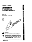
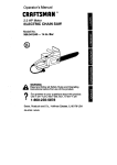
Safety Hat
Snug
Fitting
Clothing
Eye Protection
Heavy Duty Gloves
Safety
Safety Chaps
Shoe_
Figure 1
KNOW
•
YOUR
SAW
Read your operator's manual carefully until you
completely understand and can follow all safety rules,
precautions, and operating instructionsbefore attempting to operate the unit.
Restrict the use of your sew to adult users who understand and can follow safety rules, precautions, and
operating instructionsfound in this manual.
PLAN AHEAD
•
•
•
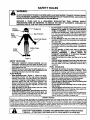
Wear protective gear. Figure 1. Always use steeltoed safety footwear with non-slip soles; snug-fitting
clothing; heavy-duty, non-slip gloves; eye protection
suchas non-fogging, vented goggles or faca screen; an
approved safety hard hat; and sound barders---ear
plugsor mufflersto protect your hearing. Regular users
should have hearing checked regularly as chain saw
noise can damage hearing.
Keep all parts of your body away from the chain
when the engine Is running.
Keep children, bystanders, end animals a minimum
of 30 feet (10 Meters) away from the work area. Do
not allow other people or animals to be near the chain
saw when startinq or operatin.qthe chain saw.
•
•
•
•
Eliminate all sources of sparks or flames In the areas where fuel Is mixed, poured, or stored. There
should be no smoking, open flames, or work that could
cause sparks. Allow engine to cool before refueling.
Mix and pour fuel In an outdoor area on bare ground; •
store fuel in a cool, dry,well ventilated place; and use an
approved, marked container for all fuel purposes.
Wipe up all fuel spills before starting saw.
Move at least 10 feet (3 meters) from the fueling site
before starting the engine,
Do not smoke while handling fuel or while operatIng the saw.
Turn the engine off and let your saw cool in a noncombustible area, not on dry leaves, strew, paper, etc.
Slowly remove fuel cap and refuel unit.
Store the unitand fuel in an area where fuel vapors cannot reach sparks or open flames from water heaters,
electric motors or switches, furnaces, etc.
SAFETY NOTICE
]
Exposureto vibrationsthroughprolongeduse of gasolinepoweredhand toolscouldcause bloodvessel or nerve damage in the |
fingers, hands, and joints of people proneto circulation
disordersor abnorma swe lings. Prolongedusein coldweatherhas been I
linkedto bloodvessel damage in otherwisehealthy people. If symptoms occursuchas numbness, pa n, ossof strength, change |
in skincoloror texture or lossoffeeling in thefingers handsor joints,discontnuethe use ofth s too and seek medica attenton I
An anti-vibration
systemdoes not guaranteethe avoidanceof these probems. Userswhooperatepowertoolson a continualand |
regularbasismustmonitorcloselytheirphysca conditionand the conditionof thisunit.
.
J
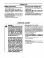
LOOK
FOR - THIS
SYMBOL TO
POINT ALERTIH
OUT IMPORTANT
SAFETYIS PRECAUTIONS.
IT MEANS
ATTENTIONII!
BECOME
YOUR SAFETY
INVOLVED.
--
'7--
SAFETY
RULES
OPERATE YOUR SAW SAFELY
• Do not operate a chain saw with one hand. Serious
injuryto the operator, helpers, bystanders or any combination of these persons may result from one-handed operation.A chain saw is intended for two-handed use.
• Operate the chain saw only in well-ventilated outdoor
areas.
• Do not operate saw from a ladder or in a tree, unless
specificallytrained to do so.
• Position all parts of your body to the left of cut and
away from the chain when the engine Is running.
• Cut wood only. Do not use your saw to pry or shove away
limbs, roots, or other objects.
• Make sure the chain will not make contact with any
object while starting the engine. Never try to start the
saw when the guide bar is in a cut or kerr.
• Use extreme caution when cutting small size brush
and saplings. Slender material can catch the chain and
be whipped toward you or pull you off balance.
• Be alert for springback when cutting a limbthat is under
tension so you will not be struck by the limb or saw when
the tension in the wood fibers is released.
• Do not put pressure on the saw at the end of a cut.
Applying pressure can cause you to lose control when the
cut is completed.
• Stop the engine before setting the saw down.
• Keep fuel and oil caps, screws, and fasteners securely
tightened.
GUARD AGAINST
KICKBACK
MAINTAIN YOUR SAW IN GOOD WORKING
ORDER
• Have all chain saw service performed by your Sears
Service Center with the exception of the items listedin the
"Customer Responsibilities"section of this manual. For
example, if impropertools are used to remove or hold the
flywheel when servicing the clutch, structural damage to
the flywheel can occur and cause the flywheel to burst.
• Make cartaln the chain stops moving when the throttle
trigger is released. For correction, refer to "Carburetor
Adjustments."
• Stop the saw if the chain strikes a foreign object.
Inspect unitand repair or replace parts as necessary.
• Disconnect the spark plug before performing any
malntenanca except for carburetor adjustments
• Never modify your saw in any way. Use only attachmonts supplied or specificallyrecommended by the manufacturer.
• Use only Sears accessories and replacement parts
as recommended.
TRANSPORTING
AND STORAGE
• Stop the unit beforetransporting.
• Allow engine to cool, cover the guide bar and chain, and
secure the unitbefore storing or transportingin a vehicle.
• Empty fuel tank before storingor transportingthe unit.Use
up any fuel left in the carburetor by starting the engine and
letting the engine run until it steps.
• Store unit and fuel in an area where fuel vapors cannot
reach sparks or open flames from water heaters, electric
motors or switches,furnaces, etc.
• Store unit so the chain cannot accidentally cause injury.
• Store the unit out of the reach of children.
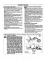
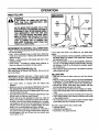
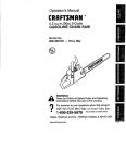
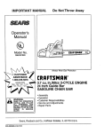
KICKBACK - Kickback is a dangerous reaction that can lead to serious injury.
Kickback
Path
WARNING
KICKBACK CAN OCCUR WHEN THE MOVING CHAIN CONTACTS AN OBJECT ATTHE
UPPER PORTION OFTHETIP OFTHE GUIDE
BAR OR WHEN THE WOOD CLOSES IN AND
PINCHES THE CHAIN IN THE CUT. CONTACT
AT THE UPPER PORTION OF THE TIP OF
THE GUIDE BAR CAN CAUSE THE CHAIN
TO DIG INTO THE OBJECT, WHICH STOPS
THE CHAIN FOR AN INSTANT.THE RESULT
IS A LIGHTNING FAST, REVERSE REACTION
WHICH KICKS THE GUIDE BAR UP AND
BACK TOWARD THE OPERATOR. IF THE
CHAIN IS PINCHED ALONG THE TOP OF
THE GUIDE BAR,THE GUIDE BAR CAN BE
DRIVEN
RAPIDLY BACK TOWARD THE
OPERATOR. EITHER OFTHESE REACTIONS
CAN CAUSE LOSS OF SAW CONTROL
WHICH CAN RESULT IN SERIOUS INJURY.
DO NOT RELY ONLY ON THE SAFETY
DEVICES PROVIDED WITH YOUR SAW. AS
A CHAIN SAW USER, YOU MUST TAKE
SPECIAL SAFETY PRECAUTIONS TO HELP
KEEP YOUR CUTTING JOBS FREE FROM
ACCIDENT OR INJURY.
Figure 2
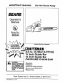
Obstructions
Clear The
Working Area
Figure 3
3
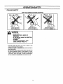
SAFETY
Never Reverse
Hand Positions
Thumb On
MAINTAIN CONTROL
_,\]
•
Handlebar
Elbow
_
_;'/m
Locked
Stand To
//_
Under
Side Of _,_
The
Le.
Of The Saw
t'
_
"_
f
Figure 4
REDUCE
THE CHANCE
OF KICKBACK
• Recognize that kickback can happen. With a basic
understanding of kickback, you can reduce the element
of surpdse which contributes to accidents.
• Never let the moving chain eentact any object at the
tip of the guide bar. Figure 2.
Keep the working area free from obstructions such
as other trees, branohes, rooks, fences, stumps, etc.
Figure 3. Eliminate or avoid any obstruction that your
chain could hit while you are cuttingthrough a particular
log or branch.
• Keep your chain sharp and properly tensioned. A
loose or dull chain can increase the chance of kickback
to occur. Follow manufacturer's chain sharpening and
maintenance instructions. Check tension at regular intervals with the engine stopped, never with the engine
running. Make sure the bar clamp nuts are securely
tightened after tensioning the chain.
• Begin and continue cutting at full throttle. If the
chain is moving at a slower speed, there is greater
chance for kickback to occur.
• Cut one log at a time.
• Use extreme caution when re-entering a previous
cut.
Do not attempt plunge cuts,
• Watch for shifting logs or other forcesthat could close
a cut and pinch or fall intochain.
Use the Reduced-Kickback Guide Bar and LowKickback Chain specified for your saw.
KICKBACK
&
RULES
SAFETY
FEATURES
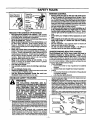
Keep a good, firm grip on the saw with both hands
when the engine Is running end don't let go, Figure
4. A firmgdp can neutralize kickback and helpyou maintain controlof the saw. Keep the fingers ofyour lefthand
encirclingand yourleftthumb under the fronthandlebar.
Keep your dght handcompletely aroundthe rear handle
whether you are dghthanded or left handed. Keep your
left arm straight with the elbow locked.
• Pc,sltlon your left hand on the front handlebar so It
is in a straight line with your right hand on the rear
handle when making bucking cuts. Figure 4. Never
reverse dght and left hand positions for any type of cutting.
• Stand with your weight evenly balanced on both
feel
• Stand slightly to the left side of the saw to keep your
body from being In a direct line with the cutting
chain. Figure 4.
• Do not overreach. You could be drawn or thrown off
balance and lose control of the saw.
• Do not cut above shoulder height. It is difficultto
maintain controlof saw above shoulder height.
UNDERSTANDING
REACTIVE
FORCES
Pinch-Kickback end Pull-In occur when the chain Is
suddenly stopped by being pinched, caught, or by
contacting a foreign oh|act In the wood. This stopping
of the chain resultsin a reversal of the chain force used to
cutwood and causesthe saw to move in the Oppositedirection of the chain rotation. Either reaction can resultin loss
of control and possible serious injury.
• Pinch-Kickback
occurs when chain on top of guide bar is suddenly
stopped.
rapidly drives saw straight back toward operator.
• Pull-In
occurswhen the chain on the bottom ofthe guide bar
is suddenly stopped.
pulls the saw rapidly forward.
sample of chain saws below 3.8 cubic inch displacement specified in ANSI B175.1-1991.
Hendguard, designed to reduce the chance of your left hand
contacting _e chain if your hand slips off the front handlebar.
Position of front sndresr handlebars, designed with distance between handles and "in-line" with each other. The
spread and =in-line" position of the hands provided bythis de-
WARNING
THE FOLLOWING
FEATURES ARE INCLUDED ON YOUR SAW TO HELP REDUCE
THE HAZARD OF KICKBACK; HOWEVER,
SUCH FEATURES WILL NOT TOTALLY
ELIMINATE THIS DANGEROUS REACTION.
AS A CHAIN SAW USER, DO NOT RELY
ONLY ON SAFETY DEVICES. YOU MUST
FOLLOW ALL SAFETY PRECAUTIONS
INSTRUCTIONS, AND MAINTENANCE IN
THIS MANUAL TO HELP AVOID KICKBACK
AND OTHER FORCES WHICH CAN RESULT
IN SERIOUS INJURY.
_iing(nt_,/O_vtoO_t
oe_jertog_l_abc_,anwC_r_nd
resislal_Crei_r
•g
p"
to
eope
to " _control_
kickba
occurs.
ANSI el 75.1- 1991 - Safetyrequirements
forgasolinepoweredchain
sawsas setbytheAmedcanNationaJStandardsInstitute,Inc., StandardB175.1-1991.
Contour¢d
j/
Ded_ Gauge Ek_ga_d
__
Reduced-Kickback
Guide Bar, designed with a small radius
tip which reduces the size of the kickback danger zone on the
guidebartip. Figure5. A Reduced-KickbackGuide Barisone
which has been demonstrated to significantlyreduce the number and seriousness of kickbackswhen tested in accordance
withANSI B175.t.
1991
Low--Klokbeck Chain, designed with a contoured depth
gauge and guard link which deflect kickback force and allow
woodtograduallyrideintothecutter.
Figure5. Low-Kickback
Chain is chain which has met kickback pedormance requirements of ANSI B175.1-1991 when tested on a representative
-4-
Reduced )Ockback
Symmet,ical Guide Bar
Symmet,_cll
auk_
Bar
Guard k_
Smell
_min
Radius T_O
_. _ _edually Ride
Chain With High
_
Potlm_d
Large
RadkJS Tip
Figure 5
_nto Cutter
CONGRATULATIONS
on your pumhaseof
PRODUCT SPECIFICATIONS
a Sears
Craftsman Gasoline Chain Saw. It has been designed, engineered and manufactured to give you the best possible
dependability and performance.
GUIDE
Should you experience any problems you cannot easily
remedy, please contact your nearest Sears Service Center/Department. Sears has competent, well trained technicians and the proper tools to service or repair this unit.
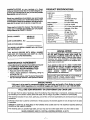
DISPLACEMENT:.................2.2 CubicInches(36cc)
ENGINE:................................2-cycleAir Cooled
FUEL MIX:.............................40:1 (3.2oz oilper gallongas)
OILER:...................................Automatic,6.8 oz Tank
IGNITION: .............................SolidState
Please read and retain this manual. The Instructions will
enable you to assemble and maintain your unit properly,
Always observe the "SAFETY RULES."
(Airgap .010"-.014")
IGNITIONTIMING:................ Non-Adjustable,
Fixed
SPARKPLUGTYPE: ............ ChampionCJ-7Y
SPARKPLUG GAP:............... 025"(.65mm)
MUFFLER:............................SparkArrestingScreen
ENGINE RPM: ...................... 12,600RPM Maximum
358.351141
358.351061
MODEL NUMBER:
DATE CODEJSERIAL
BAR:
351141................................14" (36cm)
351061 ...............................16" (40cm)
CHAIN: ..................................Low Profile 3/8" Pitch
ChromeCutters
NO.
DATE OF PURCHASE:
THE MODEL AND SERIAL NUMBER WILL BE FOUND
ON THE PRODUCT.
SPECIAL
IYOU SHOULD RECORD BOTH SERIAL NUMBEF_
AND DATE OF PURCHASE AND KEEP IN A SAFE
PLACE FOR FUTURE REFERENCE.
MAINTENANCE
AGREEMENT
A Sears Maintenance Agreement is available on this product. Contact your nearest Sears Store for details.
CUSTOMER
•
•
NOTICE
Your saw is equipped with s temperature limiting muffler and spark arresting screen which meets the
requirements of California Codes 4442 and 4443. All
U.S.forestland and the statesof California,Idaho,Maine,
Minnesota,New Jersey,Washington,and Oregon require
many internalcombustionenginesto be equippedwith a
sparkarrestorscreenby law.
If you operate a chain saw in s state or locale where
such regulations exist, you are legally responslMe for
maintaining the operating condition of these parts.
Failure to do so is a violation of the law. Refer to the
Spark
Arrestor
section
under
"Customer
Responsibilities" for maintenance.
RESPONSIBILITIES
Read and observe the safety rules.
Follow a regular schedule in maintaining, caring for,
and using your unit.
Followthe instructionsunder"Customer Responsibilities" and "Storage" sections of this Operator's Manual.
MANUFACTURED
UNDER ONE OR MORE OF THE FOLLOWING U.S.
PATENTS: 5,367,98S;
4.94e,o2_,; 4,370,B55;
4,302,879;
4,197,640;
D325,330.OTHER
U.S.AND FOREIGN PATENTS PENDING,
SPECIAL NOTICE
If this saw is to be used for commercial logging, you must order end install a Chain Brake, to comply
with Federal OSHA Regulations for Commercial Logging see Repair Parts list or call 1-800-235-5878.
FULL ONE YEAR WARRANTY
ON CRAFTSMAN
GAS CHAIN SAW
For one year from the date of purchase, when this Craftsman Gas Chain Saw is maintained, lubricated and tunedup according to the owner's manual, Sears will repair, free of charge, any defect in material or workmanship.
This warranty excludes the bar, chain, spark plug, and air filter, which are expendable parts and become worn during
normal use.
If this Gas Chain Saw is used for commercial or rental purposes, this warranty applies for only 30 days from the date
of purchase.
WARRANTY SERVICE IS AVAILABLE BY RETURNING THIS CHAIN SAW TO THE NEAREST SEARS SERVICE
CENTER IN THE UNITED STATES.
This warranty gives you specific legal rights, and you may also have other rights which vary from state to state.
SEARS, ROEBUCK AND CO., DI617WA, HOFFMAN ESTATES, IL 60179
-5-
TABLE OF CONTENTS
Safety Rules ...................................................................... 2
Product Specifications ....................................................... 5
Warranty ............................................................................
5
Accessories ....................................................................... 6
Operation ........................................................................... 8
Customer Responsibilities ............................................... 17
Service and Adjustments ................................................ 22
Storage ............................................................................
27
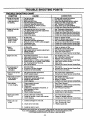
Trouble Shooting Points .................................................. 28
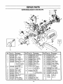
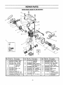
Repair Parts ....................................................................
29
Repair Parts Ordering/Service .......................... Back Cover
INDEX
A
Accessories ....................................................................... 6
Air Filter ........................................................................... 20
B
Bar and Chain Oil ............................................................ 10
Bucking ............................................................................
15
C
Carburetor Adjustments .................................................. 25
Carton Contents ................................................................ 7
Chain Adjustment ............................................................ 22
Chain Oiler ........................................................................ 9
Chain Sharpening ........................................................... 17
Customer Responsibilities ............................................... 14
Spark Plug ................................................................... 20
E
Engine
Fuel/Oil ......................................................................... 10
Spark Plug ................................................................... 20
Starting ......................................................................... 11
Storage ........................................................................ 27
F
Fuel Filter ........................................................................ 21
Fueling .............................................................................
10
G
Guide Bar and Chain Oil ................................................. 10
Guide Bar Maintenance .................................................. 19
H
How To Use Your Chain Saw ............................................. 9
K
Know Your Chain Sew ....................................................... 8
L
Limbing............................................................................
16
M
Maintenance Schedule .................................................... 17
Model Number ................................................................... 5
Muffler .............................................................................
20
O
Operation ...........................................................................
8
Ordering Repair Parts ....................................... Back Cover
P
Product Specifications....................................................... 5
Pruning ............................................................................
16
R
Repair Parts .................................................................... 29
S
Service and Adjustments ................................................ 22
Spark Arrestor Screen ..................................................... 20
Starter Rope .................................................................... 23
Starting ............................................................................
11
Storage ............................................................................
27
T
Throttle Control Group ...................................................... 9
Trouble Shooting Points .................................................. 28
Tree Felling ......................................................................
12
W
Warranty ............................................................................
5
ACCESSORIES
These accessories and attachments were available when the unitwas originally purchased.They are also available at most
Sears retail outletsand service (:enters. Most Sears stores can order these items for you when you providethe model number of your unit.
PERFORMANCE
Spark Plug
Air Filter
2-cycle
Gas Can
Bar Oil
Oil
_
Engine
3.2 oz.
8 oz.
16 oz,
1 qt.
1 gal.
MAINTENANCE
•
Safety
-6-
_
Chain
_
]prHoetmcitnogn"
[
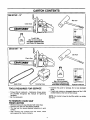
CARTON CONTENTS
358-351141
- 14"
_r_ol
(Bar Oil not included)
Fuel/Oil
Mix
Purchase
Craftsman
Bar
and Chain Oil Separately
358-351061
- 16"
Operator's Manual
{_
Bar Tool
Chain Saw
i oP==.i _
Extra Chain
TOOLS REQUIRED
Fuel/Oil Mix
(Bar Oil not included)
Purchase Craftsman Bar
and Chain Oil Separately
Carrying Case
FOR SERVICE
• Torque Wrench (optional) - Reference torque values
are provided throughout this manual for tightening
hardware.
• Bar Tool (included)
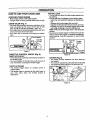
TO REMOVE CHAIN SAW
FROM CARTON
• Remove loose parts bag included with Chain Saw.
• Remove your saw from the packing material.
• You may use the opened packing matedal as a work
surface.
• After removing the contents from the carton, check
parts against the Carton Contents.
•
•
Operator's Manual
Examine the parts for damage. Do not use damaged
parts.
If parts are missing or damaged please call the 1-800
number listed on the frontof this manual
NOTE: It is normal to hear the fuel filter rattle in an empty
fuel tank.
ii
111
•
m
ill
,
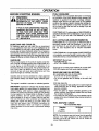
OPERATION
i
KNOWYOUR
,J
CHAIN SAW (Fig, 6)
READ THIS OPERATOR'S MANUAL AND SAFETY RULES BEFORE OPERATING YOUR CHAIN SAW. Compare the
illustrationswith your uni_to familiarize yourselt with the locationof the various controlsand adjustments. Save thismanual
for future reference.
HAt,K) GUARD _
_
H_NDLE
STARTER
ROPE HANDLE
FRONT
ON/STOP
CH/_N
PRIMER
CRRFTgMRN°
BAR OIL
FILL CAP
FUEL MIX
STARTER
FILL CAP /
CYLINDER COVER
FAST IDLE
LOCK
HOUSING
THROTTLE
LOCKOUT
ADJUSTING
SCREW
_1_
11r
CHAIN TRAVEL
DIRECTION
REAR
HANDLE
CRfl
THROTTLE
TRIGGER
CHOKE
KNOB
BAR CLAMP
_
CHAIN
CATCHER
I CLAMP
NUTS
Figure 6
Listed by Underwriters Laboratories, Inc.
in accordance with American National Standards for Gasotine-Powered Chain Saw,= Safety Requirements
(ANSI B175.1-1991).
The THROTTLE TRIGGER controls engine speed.
The GUIDE BAR is designed to carry the chain.
The CU'I_'ERS are designed to cut the wood.
The BAR CLAMP NUTS are designed to hold the guide
bar after adjustments have been completed.
The ADJUSTING SCREW is designed to tension the
chain on the guide bar,
The PRIMER BULB circulates fuel to the carburetor.
The ONiSTOP SWITCH is used to stop the engine.
The STARTER ROPE HANDLE is used for starting the
engine.
The CHOKE KNOB activates the choke to provide additional fuel to the engine when starting a cold engine.
The THRO]_LE
LOCKOUT prevents the THROTTLE
TRIGGER from being squeezed accidentally.
The FAST IDLE LOCK allows for faster engine speeds
during starting.
-8-
OPERATION
HOWTO
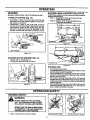
FAST IDLE LOCK
• The fast idle lock allows for faster engine speeds during starting.
• The fast idle lock is engaged by the followingsteps:
- Grasp the rear handle and depress the throttle lockout.
- Squeeze the throttle trigger fully and hold.
- Depress the fast idle lock with your thumb and hold.
- Release your grip on the throttle trigger and throttle
lock while continuing to hold the fast idle lock.
NOTE: Verify the throttle trigger stays in the advanced
position.
• Squeezing the throttle trigger will release the fast idle
setting. If the throttle trigger is squeezed accidentally
during starting, it will be necessary, to reset throttle
advance.
USE YOUR CHAIN SAW
STOPPING
YOUR ENGINE
• Move on/stop switch to the "stop" position.
• If engine does not stop, pull blue choke knob out fully.
CHAIN OILER (Fig. 7)
• The chain oiler provides continuous lubrication to the
chain and guide bar. Be sure to fill the bar oil tank
when you fill the fuel tank (Capacity = 6.8 fLoz.).
• Your chain saw will consume approximately one tank
of bar oil for each tank of fuel used.
• Your chain oiler is automatic and requires no adjustroent,
Bar
Oil Fill
Cap
Fuel Mix
II Cap
CRRFTSMRN"
CRRFT_MRN"
Figure 7
THRO'I-rLE
CONTROL
Trigger
GROUP (Fig. 8)
Figure 8
THROTTLE LOCKOUT
• The throttle lockout prevents unintentional actuation of
the throttle trigger.
• You must depress the throttle lockout with the palm of
your hand before actuating the throttle trigger.
CHOKE
(Fig. 9)
• The choke provides additional fuel when starting a
cold engine,
• The choke is actuated by pullingthe blue choke knob.
• The choke has three positions: off, partial and full.
THROTTLE TRIGGER
• The throttle trigger allows for variable control of
engine speed.
• The throttle trigger is actuated by the index finger on
your right hand. (After the throttle lockout is
depressed.)
Choke Positions
O_ff -_p!_iaiiii!,,
Figure 9
-9-
OPERATION
BEFORE
STARTING
ENGINE:
FUEL STABILIZER
Fuel stabilizer is an acceptable alternative in minimizing
the formation of fuel gum deposits during storage. Add
stabilizer to gasoline in fuel tank or storage container.
Always follow the fuel mix ratio found on the stabilizer
container. Run engine at least 5 minutes after adding stabilizer to allow the stabilizer to reach the carburetor.You
do not have to drain the fuel tank for storage if you are
using fuel stabilizer.
WARNING:
BE SURE TO READ THE FUEL HANDLING
INFORMATION IN THE SAFETY RULES
SECTION ON PAGE 2 OF THIS MANUAL
BEFORE YOU BEGIN.
IF YOU DO NOT UNDERSTAND THE FUEL
HANDLING SECTION DO NOT ATTEMPT
TO FUEL YOUR UNIT; SEEK HELP FROM
SOMEONE THAT DOES UNDERSTAND
THE FUEL HANDLING SECTION OR CALL
THE CUSTOMER ASSISTANCE HOTMNE
AT 1-800-235-5878,
CRAFTSMAN 40:1 2-cycle engine oil (AIR-COOLED) is
specifically blended with fuel stabilizers.If you do not use
this Sears oil, you can add a fuel stabilizer to your fuel
tank.
40:1 2-CYCLE
AIR-COOLED
ENGINE OIL
CRAFTSMAN 40:1 2-cycle engine oil (AIR-COOLED) is
specifically blended with fuel stabilizers. If you do not
use this Sears oil, you can add a fuel stabilizer to your
fuel mix. See "Gasoline and oil mixture" instructions
below.
GUIDE BAR AND CHAIN OIL
For maximum guide bar and chain lifo, we recommend
you use Craftsman chain saw bar oil if Craftsman bar oil
is not available, you may use a good grade SAE30 oil until
you are able to obtain Craftsman brand. The oil output is
automatically metered during operation.Your saw will use
approximately one tank of bar oilfor every tank of fuel mix.
Always fill the bar oil tank when you fill the fuel tank.
If CRAFTSMAN 40:1 2-cycle engine oil (AIR-COOLED) is
not available, use a good quality 2-cycle engine oil (AIRCOOLED) that has a recommended fuel mix ratio of 40:1.
IMPORTANT! Do not use:
• AUTOMOTIVE OIL
• BOAT OILS (NMMA, BIA, etc.)
GASOLINE
The two-cycle engine on this product requires a fuel mixture of regular unleaded gasoline and a high quality 40:1
2-cycle engine oil (AIR-COOLED) for lubrication of the
bearings and other moving parts. The correct fuel/oil mixture is 40:1 (see Fuel Mixture Chart).Too little oil or the
incorrect oil type will cause poor performance and may
cause the engine to overheat and seize.
These oils do not have proper additives for 2-cycle (AIRCOOLED) engines and can cause engine damage.
GASOLINE
AND OIL MIXTURE
MIX GASOLINE AND OIL AS FOLLOWS:
• Consult chart for correct quantities.
• Do not mix gasoline and oil directly in the unit's fuel
tank.
Gasoline and oil must be premixed in a clean approved
fuel container. Always use fresh regular unleaded gasoline.
FOR ONE GALLON:
• Pour 3.2 ounces of high quality, 40:1 2-cycle engine oil
(AIR-COOLED) into an empty, approved one gallon
gasoline container.
• Add one gallon of regular unleaded gasoline to the
gallon container, then securely replace the cap. Shake
the container momentarily.
• The mixture is now ready for use. Fuel stabilizer can be
added at this time if desired; follow mixing instructions
on the label.
This engine is certified to operate on unleaded gasoline.
IMPORTANT: Experience indicates that alcohol blended
fuels called gasohol (or using ethanol or methanol) can
attract moisture, which leads to oil/gas separation and
formation of acids during storage. Acidic gas can damage
the fuel system of an engine while in storage. To avoid
engine problems, the fuel system should be emptied
before storage for 30 days or longer. Drain the gas tank,
then run the fuel out of the carburetor and fuel lines by
starting the engine and letting it run until it stops. Use
fresh fuel next season. See STORAGE instructions for
additional information. Never use engine or carburetor
cleaner products in the fuel tank or permanent damage
may occur.
FUEL MIXTURE
CHART
40:1 FuehOil Mix Ratio
1 gallon
2.5 gallons
3.2
8.0
NOTE: Fuel containers may hold more than the specified
amount. If too much gasoline is in the container, the
resulting gas-to-oil fuel mixture will not be correct for
proper engine operation.
-10-
OPERATION
STOPPING
YOUR ENGINE
• Move on/stop switch to the "Stop" position.
• If engine does not stop, pull blue choke knob out fully.
_
ALWAYS
GLOVES; SAFETY
ARNING:WEAR
FOOTWEAR, SNUG-FITTING CLOTHING;
AND EYE, HEARING, AND HEAD PROTECTION DEVICES WHEN OPERATING
A CHAIN SAW.
THE CHAIN MUST NOT MOVE WHEN
THE ENGINE RUNS AT IDLE SPEED•
REFER
TO
THE
"CARBURETOR
ADJUSTMENTS:
SECTION FOR CORRECTION.
AVOID ANY CONTACT WITH THE MU_
FLER. A HOT MUFFLER CAN CAUSE
SERIOUSBURNS•
_.l
Figure 10
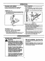
STARTING
COLD ENGINE START AND WARM ENGINE
START AFTER RUNNING OUT OF FUEL
A WARM ENGINE
•
•
•
•
Move "On/Stop" switch to the =On"position.
Activate fast idle control.
Be sure choke is in the off position.
With saw on ground, grip front handle with lefthand and
place your right foot throughopening in rear handle.
• Pull starter rope handle until engine starts.
• Squeeze and release throttle trigger to return engine
to idle speed.
NOTE: Check chain tension using instructions in the
"Service and Adjustment' section.
• Before first use.
• After 1 minute of operation•
TO START ENGINE (Fig. 10 & 11)
• _0
Partial Full
Right Hand
on
•
Starter R
Handle.!/
STARTING POSITION
"o. ond
• Fuel engine with 40:1 fuel mix (3.2 oz. to 1 gal. gas).
• Fill bar oil tank with bar oil.Your saw will use approximately one tank of bar oil for each tank of fuel mix.
t
Front Handle
• Prime engine by pressing primer bulb six times.
• Turn on ignition by moving on/stop switch to the "ON"
position.
• Actuate choke by pulling blue choke knob fu(I,/ou[
Then set the saw on the ground.Grip the front handle
with your left hand and place your right foot through
Right Foot through Opening in Rear Handle
opening in rear handle.
• Set fast idle by depressing the throttle lock with your
Figure 11
right hand. Then squeeze throttle trigger and hold.
With your thumb, press the fast idle lock down and
DIFFICULT
STARTING OR FLOODED
ENGINE
hold. Next, release the throttle trigger.
The engine may be flooded with too much fuel it it has
• IF THROTTLE TRIGGER IS SQUEEZED ACCIDENnot started after 10 pulls.
TALLY DURING STARTING IT WILL BE NECESSARYTO RESETTHE FAST IDLE LOCK.
Flooded engines can be cleared of excess fuel with the
NOTE: When pulling the starter rope, do not use the full
following procedure:
extent of the rope. Do not let the starter snap back hold
• Activate the fast idle lock.
the handle and let the rope rewind slowly.
• Verify that on/stop switch is in the "ON" position. "
• Pull starter rope handle with your right hand until the
• Push the choke knob to the "OFF" position
engine attempts to start. Then push the blue choke
• With saw on ground, grip front handle with left hand
knob in to the partial position. Resume pulling handle
and place right foot through opening in rear handle.
until engine starts.
• Pull starter rope handle until engine starts.
• Above 40 degrees, allow engine to run for approximately 5 seconds, push the choke knob in to the OFF
Starting could require pulling starter rope handle many
position, then squeeze and release throttle trigger to
times depending on how badly unit is flooded.
allow engine to idle.
If engine still fails to start, refer to =TROUBLE SHOOTING" chart or call the 1-800 number listed on the front
• Below 40 degrees, allow engine to warm up 30 secpage of this manual.
onds - 1 minute with choke at partial position. Push
choke knob in to the OFF position,then squeeze and
release throttle trigger to allow engine to idle.
• To stop engine, move on/stop switch to the "STOP"
position.
-11-
OPERATION
GENERAL
OPERATION
TIPS
• Cut wood only.Do not cut metal; plastics;masonry;nonwood building materials; etc.
• Stop the saw if the chain strikes a foreign object.Inspect
the saw and repair or replace parts as necessary.
• Keep the chain out of dirt and sand. Even a small
amount of dirt will quickly dull a chain and thus increase
the possibilityof kickback.
• Begin cutting with the saw chassis against the log.
• Keep engine at full throttle during cutting procedure.
• Allow the chain to cut for you; exert only light downward
pressure. If you force the cut, damage to the bar, chain,
or engine can result.
• Release the throttle trigger as soon as the cut is completed, allowing the engine to idle. If you run the unit at
full throttle without cutting, unnecessary wear can occur
to the chain, bar, and engine.
• To avoid losing control when completing the cut, do not
put pressure on the saw dudng the end of the cut.
• Stop engine before setting unit down after operation.
To get the "feel" of using your saw before you begin a
major sawing operation, practice cutting a few small logs
using the followingtechnique:
• Accelerate engine to full throttle by squeezing the throttle trigger before entering cut.
• Never cut with engine at partial speeds.
OPERATION SAFETY
WARNING
AVOID REACTIVE
IF SAW BECOMES PINCHED OR HUNG IN
A LOG, DO NOT TRY TO FORCE IT OUT.
YOU CAN LOSE CONTROL OF THE SAW
RESULTING IN INJURY AND/OR DAMAGE
TO THE SAW. STOP THE SAW, DRIVE A
WEDGE OF PLASTIC OR WOOD INTOTHE
CUT UNTIL THE SAW CAN BE REMOVED
EASILY. RESTART THE SAW AND CAREFULLY REENTER THE CUT. TO AVOID
KICKBACK AND CHAIN DAMAGE, DO NOT
USE A METAL WEDGE. DO NOT A'I'rEMPT
TO RESTART YOUR SAW WHEN IT IS
PINCHED OR HUNG IN A LOG.
Pinch-Kickback and Pull-In occur when the chain is suddenly stopped by being "pinched,caught, or by contacting
a foreign object in the wood. This sudden stopping of the
chain results in a reversal of the chain force used to cut
wood and causes the saw to move in the opposite direction of the chain rotation. Pinch-Kickback drives the saw
straight back toward the operator. Pull-In pulls the saw
away from the operator. Either reaction can result in loss
of control and possibly serious injury.
PINCH FORCES
TO AVOID PINCH-KICKBACK:
• Be extremely aware of situations or obstructions that
can cause material to pinch the top of or otherwise stop
the chain.
• Do not cut more than one log at a time.
• Do not twist the saw as the bar is withdrawn from an
under-cut when bucking.
KICKBACK CAN OCCUR WHEN THE MOVING CHAIN CONTACTS AN OBJECT AT
THE UPPER PORTION OF THE TIP OF THE
GUIDE BAR OR WHEN THE WOOD CLOSES IN AND PINCHES THE SAW CHAIN IN
THE CUT. CONTACT ATTHE UPPER PORTION OFTHETIP OFTHE GUIDE BAR CAN
CAUSE THE CHAIN TO DIG INTO THE
OBJECT AND STOP THE CHAIN FOR AN
INSTANT, THE RESULT IS A LIGHTNING
FAST, REVERSE REACTION WHICH KICKS
THE GUIDE BAR UP AND BACK TOWARD
THE OPERATOR. IF THE SAW CHAIN IS
PINCHED ALONG THE TOP OF THE GUIDE
BAR, THE GUIDE BAR CAN BE DRIVEN
RAPIDLY BACK TOWARD THE OPERATOR.
EITHER OF THESE REACTIONS CAN
CAUSE LOSS OF SAW CONTROL WHICH
CAN RESULT IN SERIOUS INJURY.
TO AVOID PULL-IN
• Always begin cutting with the engine at full throttle and
the saw housing against wood.
• Use wedges made of plastic or wood, (never of metal)
to hold the cut open.
-12o
OPERATION
TREE FELLING
I_
_mi.im
/
/
/
/
/
/
|
F"n00"O'°n
} ,: I
IF THE TRUNK OR MMBS ARE Rot"rING,
THEY CAN FALL UNEXPECTEDLY AND
_
lop _
Notch
CAUSE SERIOUS INJURY.
AS YOU MAKE YOUR FELLING CUT, IF THE
SAW APPEARSTO BE BINDING,THETREE IS
STARTING TO FALL IN THE WRONG DIRECTION. IMMEDIATELY STOP THE SAW AND
USE A FELLING WEDGE AND MAUL (HAMMER) TO FORCE THE FELUNG CUT OPEN.
THE WEDGE WILL HOLD THE FELLING CUT
OPEN ALLOWING YOU TO REMOVE THE
SAW. KEEP EVERYONE AWAY FROM THE
TREE IN ALL DIRECTIONS.
DETERMINETHE
', '
i
0
,
I
Felling
Cut
J./...
I
/
I>>'"-" ! .... -t="
Bottom
I I//jV/
I
Notch ._.._r/1/3
i
cut
| Tree I
NATURAL FALL DIRECTION
i
,
L
Buttress
Root
Figure 12
• Wind - A tree evenlybalanced willfall in the same direction
the wind is blowing,
• Lean - Use a carpenter'slevel or plumb bob to determine
if tree has a natural lean. A leaning tree will tend to fall in
directionof lean.
• Shape - A tree will fend to fall towards side that is more
heavily branched.
• Other Factors - Contacting or nearby trees, buildings, or
wires can influence the direction the tree will fall.
CUTTING PROCEDURE
I
(Fig. 12)
After determining the Natural Fall Direction, the tree should
be cut as follows:
If your chain saw binds in the felling cut, you have three
options:
• Ifthe wrong directionof fall is acceptable,carefully remove
the felling v,_lge. CUt deeper in the notchside of the tree
until tree startsto fall.
• If the wrong direction of fall is not acceptable, attempt to
use one or morefelling wedges to force the tree in the original direc'tionof fall. Do so by drivingthe wedges deeper
intothe felling cut.
• Keep everyoneaway from the tree in alldirectionsand then
seek professionalhelp!
FELLING TIPS
IMPORTANT: BEFORE FELLING A TREE, MAKE SURE
YOU HAVE AT LEAST 3 FELLING WEDGES AND A MAUL
(HAMMER) AVAILABLEFOR USE IF NEEDED.
• Use some means to visually mark the Natural Fall
Direction.
• Mark your notch cut on the Natural Fall Direction side of the
tree approximately 18-24 inches above the ground.
• Cut top of the notch first at a 45 degree angle. Saw through
1/3 of the width of the tree.
• Cut bottom of the notch at a 45 degree angle until you meet
the top notch cut. Remove notch of wood.
• On the side of the tree opposite the notch cut, make the
felling cut.The felling cut should be 2 inches above the center point of the notch cut. Before the felling cut is complete,
use wedges to open the cut when necessary to control the
direction of the fall. Use wood or plastic wedges, but never
steel or iron, to avoid kickback and chain damage.
• Cracking sounds, widening of the felling cut, movement in
the upper branches are all signs that the tree is ready to fail.
• As tree begins to fall, turn off saw, and move quickly away
from direction of fall
-13-
• Clear the work area of debris where you can have secure
footing.
• Make sure there isenough roomforthe treeto fall.Maintain
a distanceof 2 1/2 tree lengthsfrom the nearest person or
other objects.Engine noise can drown out a warning call.
• Remove dirt, stones, loose bark, nails, staples, and wire
from the tree where cuts are to be made.
• Plan to stand on the uphill side when cuttingon a slope.
• Plan a clear retreatpath to the rear and diagonaltothe line
of fall.
• Large buttress roots should be removed prior to notch cut.
• Use a wedge ifthere is any chance that the tree will not fall
in the desired direction.
• We recommend you cut branches below shoulder height
before felling tree. (See Limbing and Pruning).
Be alert to signs that the tree is readyto fall:
• Cracking sounds.
• Widening of the felling cut.
• Movement in the upper branches.
OPERATION SAFETY
FELLING SAFETY
DON'T PUT YOURSELF IN THESE POSITIONS
f-,
Check the wind-Don't cut down wind
Check the lean-Don't cut on lean side
WARNING
DO NOT CUT:
-NEAR ELECTRICAL WIRES OR
BUILDINGS.
-IF YOU DO NOT KNOW THE DIRECTION
OF TREE FALL.
-AT NIGHT.
-DURING BAD WEATHER - RAIN,
SNOW, STRONG WIND, ETC.
• Look for decay and rot. If the trunk is rotted, it can
snap and fall toward the operator.
• Check for broken or dead branches which can fall on
you while cutting.
• Be extremely cautious with partially fallen trees that may
be poorly supported. When a tree doesn't fall completely, set the saw aside and pull down the tree with a
cable winch, blockand tackle, or tractor.To avoid injury,
do not cut down a partially fallen tree with your saw.
-14-
Check the balance-Don't cut on weighted side
OPERATION
BUCKING
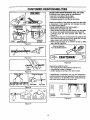
BUCKING
Buckingis cutting a fallen tree to the desired log size.
TYPES OF CUTTING
(Fig. 13)
• Overcutting - begin on the top side of the log with
the bottom of the saw chassis against the log; exert
light pressure downward.
• Undercutting - begin on the under side of the log
with the top of the saw chassis against the log; exert
light pressure upward. During undercutting, the saw
will tend to push back at you. Be prepared for this
reaction and hold the saw firmly to maintain control.
USING A SUPPORT (Fig. 15& 16)
Another log.ora stand, such as a sawhorse, may be useOas
supports wnen bucking.
• Area A- Undercut 1/3 of the way through the log.
- Finishwith an overcut.
• Area B - Overcut 1/3 of the way through the log.
- Finish with an undercut.
Undercut
\
ls'C_t_t_
2ndCut _/:L_
1.stcut
Figure 15
Saw Chassis
Figure 13
BUCKING
ONTHE
GROUND
(Fig. 14)
• Overcut with a 1/3 diameter cut.
• Roll log over and finish with an overcut.
Another Log
"- "-"
Figure 16
BUCKING TIPS
Cut shattered wood very carefully.Sharp pieces of wood
o Cut
only
at a time.
could
be one
flunglog
toward
the operator.
Use a sawhorse to cut small logs. Never allow another
person to hold the log while cutting and never hold the
log with your leg or foot.
• Do not cut in an area where logs, limbs, and roots are
tangled such as in a blown downarea. Drag the logs into
a clear area before cutting by pulling out exposed and
cleared logs first.
• Give special attention to logsunder strainto preventthe
saw from pinching. Make the first cut on the pressure
side to relieve the stress on the log.
Figure 14
OPERATION SAFETY
BUCKING SAFETY
WARNING
DO NOT STAND ON THE LOG BEING
CUT. ANY PORTION CAN ROLL CAUSING LOSS OF FOOTING AND CONTROL.
NEVER TURN THE SAW UPSIDE DOWN
TO UNDERCUT. THE SAW CANNOT BE
CONTROLLED IN THIS POSITION.
•
Use Common Sense
Stay on uphill side of tree when cutting.
-15-
_._
Maintain Secure Footing
OPERATION
iii
PRUNING AND LIMBING
Pruning is removing branches from a standing tree.
Limbing is removing branches from a felled tree.
LIMBING
(Fig. 17)
• Start at base of the felled tree and work toward the top.
• Leave the larger limbs underneath the felled tree to support the tree as you work.
PRUNING PROCEDURE
• Cut I - Undercut 1/3 of the way through the limb near
the trunk of the tree.
• Cut 2 - Finish with an ovemut farther out from the
trunk until the limb falls. Keep out of the way of the
falling limb.
• Pruning Cut - Cut the limb stump flush at the edge of
the collar.
i_
Cut 2
Figure 18
PRUNING
AND LIMBING TIPS
•
Figure 17
PRUNING
(Fig. 18 )
Small branches -smaller than width of guidebar.
Large branches - larger than width of guidebar.
• Remove small limbs with one cut.
• Remove larger, supporting branches with the 1/3 - 2/3
cutting techniques described in the bucking section.
Work slowly, keeping both hands firmly gripped on the
saw. Maintain secure footing and balance.
• Keep a clear work area. Frequently clear brenches outof
the way to avoid tripping over them.
• Leave the larger limbsunderneath the felled tree to supportthe tree as you work.
• Start at the base of the felled tree and work toward the
top.
• Keep the tree between you and the chain. Cut from the
side of the tree opposite the branch you are cutting.
• Limit pruning to limbs shoulder height or below.
• Keep out of the way of the falling limb.
OPERATION SAFETY
PRUNING AND LIMBING SAFETY
Watch out for aprlngpolea.
Use extreme caution
when cutting small size limbs. Slender material may
catch the saw chain and be whipped toward you or pull
you off balance.
WARNING
NEVER CLIMB INTO A TREE TO LIMB OR
PRUNE UNLESS SPECIFICALLY TRAINED
TO DO SO. DO NOT STAND ON LADDERS,
PLATFORMS, A LOG, OR IN ANY POSITION
WHICH CAN CAUSE YOU TO LOSE YOUR
BALANCE OR CONTROL OF THE SAW.
Be alert for sprlngbeck. Watch out for branches that
are bent or under pressure as you are cutting to avoid
being struck by the branch or the saw when the tension
in the wood fibers is released,
BE ALERT FOR AND GUARD AGAINST
KICKBACK. DO NOT ALLOW THE MOVING
CHAIN TO CONTACT ANY OTHER
BRANCHES OR OBJECTS AT THE NOSE
OF THE GUIDE BAR WHEN LIMBING OR
PRUNING. ALLOWING SUCH CONTACT
CAN RESULT IN SERIOUS INJURY.
DO NOT CUT IF BRANCHES ARE HIGHER
THAN YOUR SHOULDER. GET A PROFESSIONAL TO DO THE JOB. THIS MAY RESULT IN SERIOUS INJURY.
-16-
CUSTOMER RESPONSIBILITIES
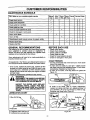
MAINTENANCE
SCHEDULE
Fill in dates as you complete regular service
Before
Use
Check chain tension
v"
Check chain sharpness
v"
Check guide bar condition
v"
Check guide bar lube
v"
Check for loose fasteners & parts
v"
Check for damaged or worn parts
v"
After
Use
Every Every Yearly Service Dates
5 Hrs. 25 Hrs.
v"
v"
Clean unit & labels
v"
Clean air filter
Clean/inspect spark arrestor screen & inspect muffler
v"
Replace spark plug
v"
v"
Replace fuel filter
GENERAL RECOMMENDATIONS
BEFORE EACH USE
The warranty on this unit does not cover items that have
been subjected to operator abuse or negligence. To
receive full value from the warranty, the operator must
maintain unit as instructed in this manual.
•
•
•
•
•
•
Some adjustments will need to be made periodically to
properly maintain your unit.
chain tension
chain sharpness
guide bar condition
guide bar lube
for loose fasteners & parts
for damaged or worn parts
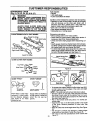
CHAIN TENSION
All adjustmentsin the "Service and Adjustments"sectionof
this manual shouldbe checked at least once each season.
• Use the screwdriver end of the bar tool to move chain
around the guide bar.
• If chain does not rotate, it is too tight - slightly loosen
bar clamp nuts and turn adjusting screw 1/4 turn countemlockwise. Retighten bar clamp nuts.
• If chain is too loose, it will sag below the guide bar
Figure 19.
• Once a year, replace the spark plug, replace air filter
element and check guide bar and chain for wear. A new
spark plug and a clean/new air filter element assures
proper air-fuel mixture and helps your engine run better
and last longer.
Followthe maintenance schedule in this manual.
_b
Check
Check
Check
Check
Check
Check
DISCONNECTTHE SPARK PLUG BEFORE i
WARNING
PERFORMING MAINTENANCE
EXCEPT! i
FOR CARBURETOR ADJUSTMENTS.
!
INSPECT THE ENTIRE UNIT. REPLACE
DAMAGED PARTS. CHECK FOR FUEL
LEAKS AND MAKE SURE ALL FASTENERS ARE IN PLACE AND SECURELY FASTENED.
LUBRICATION
Figure 19
• If chain is too loose, refer to "Chain Adjustment."
Loosen bar clamp nuts; then, turn adjusting screw 1/4
turn clockwise. Lift up tip of guide bar to check for sag.
Retighten bar clamp nuts, Figure 20.
CHART
Adjusting Screw
,,,Turn
I F,//._f
Bar ClampGUidi Bar '
CRRFTSMR
Bar"I[
/
Tool
(D Craftsman chain saw bar oil
® Craftsman bar sprocket lube
Figure 20
o17-
CUSTOMER
RESPONSIBILITIES
SHARPENING
CHAIN
(Fig. 21,22, 23, 24, 25, 26 & 27)
IMPROPER CHAIN SHARPENING TECHARNING
NIQUES
AND/OR DEPTH GAUGE MAINTENANCE WILL INCREASE THE CHANCE
OF KICKBACK, WHICH CAN RESULT IN
SERIOUS INJURY.
_
ALWAYS WEAR GLOVES WHEN HANDLING THE CHAIN. THE CHAIN CAN BE
SHARP ENOUGH TO CUT YOU EVEN
THOUGH IT ISTOO DULLTO CUT WOOD.
CHAIN TERMINOLOGY & PART NAMES
Preset Tie Strap
Left Hand Cutter
___,_
Drive Link
Right Hand Cut_;r_
--
Tools required:
• Flat file
• .025 depth gauge
• 4.5mm round file & file holder
Conditions which indicate the need for chainsharpening:
• Reduction in size of wood chips.The size of the wood
chip will decrease as the chain gets duller" until it
becomes more like a powder than a chip. Note that
dead or rotted wood will not produce a good chip.
• Saw cuts to one side or at an angle.
• Saw requires excessive force to cut.
• Noticeable loss of cutting speed.
Sharpening instructions:
• Move on/stop switch to the "stop" position.
• Check chain for proper tension. Adjust chain tension if
necessary. (See Chain Tension/Adjustment).
• Check and lower depth gauges before sharpening cutters.
• Depth gauges should be checked every third sharpening.When cutting frozen wood the depth gauges should
be checked each time you sharpen the chain.
• To check depth gauge, place gauge tool on cutter. If the
depth gauge projects above the tool, then file it level to
the top of the depth gauge tool. See Figure 21.
Guard Tie Strap
CHAIN CUTTER PART NAMES
Top Plate ._,..,..,_._G,ullet
Side Plate _-_/_DeP;e
Figure 21
.030"
_1 Rounded
CHAIN "PITCH"
O-Y_O
CHAIN"GAUGE"
Right Way
This distance
divideCl by tw_
Pitch refers to chain measurement. A chain's pitch
is the distance between
any three of its rivets
divided by two.
Wrong Way
Figure 22
• To sharpen the cutters, position the file holder level (90 °)
so that it rests on the top edges of the cutter and depth
Thickness of boitorn _
section of drive link
gauge. See Figure 23.
NOTE - The chain has both left and right hand cutters.
Gauge refers to thickness
• Sharpen cutters on one side of the chain first. File from
the inside of each cutter to the outside.Then turn your
of that portion of drive link
saw around and repeat the process for the other side of
which fits into saw bar i
the chain. See Figure 24.
groove.
• File on the forward stroke only. Use 2 or 3 strokes per
cutting edge.
• Keep the 30° line on the file holder parallel to the center
of the chain. Reverse procedure for other side. See
Figure 25.
• Keep all cutters the same length when filing. See Figure
26.
• File enough to remove any damage to cutting edges
(side plate and top plate) of cutter. See Figure 26.
• File chain to meet the specifications shown below. See
Figure 27.
-18-
CUSTOMER RESPONSIBILITIES
GUIDE BAR MAINTENANCE
(Fig. 28 & 29)
Conditions which require guide bar maintenance:
• saw cuts to one side or at an angle.
• saw has to be forced through the cut.
• inadequate supply of oil to the bar and chain.
Check the condition of the guide bar each time the chain
is sharpened. A worn guide bar will damage the chain
and make cutting difficult.
• Move on/stop switch to the "stop"position.
• Remove bar and chain from saw.
• Clean all saw dust and any other debris from the guide
bar groove and guide bar lubrication hole. Figure 28.
• Lubricate guide bar hole sprocket after each use.
Figure 28.
• Burring of bar rails is a normal process of guide bar rail
wear. Remove these burrs by filing guide bar rail side
edges square with a flat file. Figure 29.
• Restore square edges to an uneven rail top by filing
with a flat file. Figure 29.
I FRONT VIEW
I SIDe VIEW ]
File Holder
__/...,__
File
"_
Cutter
Depth Gauge
Guide Bar
& Chain
Figure 23
Remove Sawdust
From Guide Bar Groove
Outside
_
"--_---"-.-_
--
Inside _,_
CRRFTSMRN" "
Figure 24
Figure 28
Replace the guide bar when:
• the inside groove of the guide bar rails is worn.
• the guide bar is bent or cracked.
• excess heating or burring of the rails is noted.
Figure 25
Cutters Same
Remove Damage
Side Plate
If replacement is necessary, use only the replacement
reduced kickback guide bar specified for your saw in the
repair parts list or as specified on the replacement bar
and chain decal located on the chain saw.
Top Plate
Figure 26
I
J
85°
Correct
Groove
I
I
I
Wom Grooves
Figure 29
25 °
Figure 27
-19-
File Edges
Square
CUSTOMER
CHECK FOR DAMAGED/WORN
RESPONSIBILITIES
PARTS
REPLACE
The followingdamaged/worn parts should be referred to
your Sears Service Center.
NOTE: It is normal for a small amount of oil to appear
under the saw after engine stops. Do not confusethis with
a leakino oil tank.
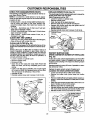
SPARK PLUG (Fig, 31)
The spark plugshould be replaced each year to ensurethe
engine starts easier and runs better.
Spark Plug gap shouldbe .025".
• Loosen 3 screws on cylinder cover.
• Remove cylinder cover.
• Twist, then pull off the spark plug boot.
• Remove spark plug from cylinder and discard.
• Replace with correct spark plug and tighten with 3/4"
socket wrench (10-12 Ib-ft).
• Reinstall spark plug boot.
Reinstall cylinder cover and 3 screws (15-20 in-lb).
• On/Stop Switch - ensure on/stop switch functionsproperly by moving the switch to the =Stop"position and
assure that engine stops, then restart your engine and
continue.
• Fuel Tank - discontinue use of chain saw if fuel tank
show signs of damage or leaks.
• Oil Tank - discontinue use of chain saw ifoil tank shows
signs of damage or leaks.
• Chain Catcher - replace chain catcher if bent, cut, or
damaged in any way.
Cylinder Cover
Screws
CLEAN UNIT AND LABELS
• Clean the unit using a damp cloth with a mild detergent.
• Wipe off the unit with a clean dry cloth.
CLEAN AIR FILTE_ (Fig. 30)
A dirty air filter decreases the life and performance of the
engine and increases fuel consumption and harmfulemissions.
Always clean your air filter after 15 tanks of fuel or 5
hours of operation, whichever is less. Clean more frequently in dusty conditions.A used air filter can never be
completely cleaned. It is advisable to replace your air filter with a new one after every 50 hours of operation, or
annually,whichever is less.
• Loosen 3 screws on cylinder cover.
• Remove cylinder cover.
• Remove air filter.
• Clean the air filter using hot soapy water. Rinse with
clean cool water, and air dry completely prior to reinstalling.
• Lightly oil air filter prior to installing. Use 2-cycle engine
oil or motor oil (SAE 30). Squeeze excess oil from filter.
This will improve the efficiency of the air filter.
• Reinstall air filter.
• Reinstall cylinder cover and 3 screws (15-20 in-lbs).
Figure 31
INSPECT
SPARK ARRESTOR SCREEN (IF INSTALLED)
(Fig. 32)
As the unit is used, carbon depositsbuild up on the muffler
and spark arrestor screen (if installed), and must be removed to avoid creating a fire hazard or affecting engine
performance.
Required cleaning is every 25 hours of operation or annually, whichever is less.
Replace the spark arrestor screen if breaks occur.
CLEANING THE SPARK ARRESTOR SCREEN
• Loosen and remove the 2 mufflercover screws.
• Remove the muffler cover (cover snaps into muffler
body).
• Remove muffler diffuserand spark arrestor screen assembly. Notice the orientationof these parts for reassembly.
• Clean the spark arrestor screen with a wire brush or replace if breaks are found in the screen.
• Replace any broken or cracked parts.
• Reinstall diffuser and spark arrestor screen assembly
with round holes facing up and towards mufflercover.
• Reinstall muffler cover and 2 screws (7-8 ft-lbs).
Cylinder
3over
:rews
Air
Filter
MUFFLER AND
Cylinder
Cover
_Muffler
Diffuser/
_'_S
Pa_ rA'_eeSt°r
_,.,_/j
,_/
Muffler
Cover
Figure 32
_
G/ Z ,.u.,o,
Figure '30
Muffler
Body
-20-
Cover
CUSTOMER
REPLACE
RESPONSIBILITIES
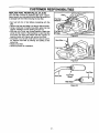
FUEL FILTER (Fig. 33, 34, & 35)
The fuel filter should be replaced after each season.
Never operate your saw without a fuel filter. Be careful not
to damage fuel line while removing the fuel filter.
• Run fuel tank dry of fuel before proceeding with this
step.
• Remove fuel cap and allow it to hang to side of motor.
• Using a small pair ot needle nose pliers, grasp fuel cap
retainer, holding it in tank opening and pull out.
• With cap out of tank, use a small section of bent wire
similar to that shown in the illustration to catch fuel line
and slowly pull from tank. When fuel tilter appears in
opening, grasp with fingers and remove from tank.
• Once filter is out of tank, hold fuel line close to fuel filter. Remove fuel filter by twisting and pulling at the
same time.
• Replace fuel filter.
• Reverse process for installation.
Fill Cap
Figure 33
Figure 34
Fuel Filter
Fuel Line
Fuel Filter
Barrel
Filter Neck *''_ I_
Figure 35
"21 -
SERVICE
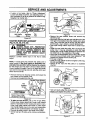
CHAIN REPLACEMENT
AND ADJUSTMENTS
• Install bar clamp nuts and fingertightenonly. Do not fightan
anyfurther at this point.
• Now proceedto the"Chain Adjustmenf'seclJon.
(Fig_.36, 37, 38 & 39)
handling chain.The chain is sharp and can cut
CAUTION:
Wear
protective
you even when
it Is not
moving. gloves when
It is normal for a new chain to stretch. Because
of this initial stretch during the first 15-30
minutes of operation you should recheck your
chain tension frequently and adjust the chain
tension as required. See chain tension section.
•
•
•
•
•
CRRFTSMRN"
Move on/stop switch to the "Stop" position.
Replacegle old chain when it becomes wornor damaged.
Use only. the low-Kickback replacement chain specified in
the repair parts list or as specified on the replacement bar
and chain decal located on the chain saw.
See your Sears Service Center to replace and sharpen individual cutters for matching your chain.
Loosen and remove the 2 bar clamp nuts.
Remove bar clamp.
Remove the old chain.
'Bar Clamp Nuts
F'_ure39
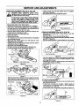
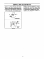
CHAIN ADJUSTMENT (Fig. 40, 41, 42 & 43)
.
.
• Roll chain around guide bar to ensure kinks do no[ exist
(rotates freoly).
Assure bar clamp nuts are loosened(finger tight).
Turn adjustingscrew clockwise until chain just _rely touches
the bottom of guide bar.
• Rollchainaroundguidebar toensurealllinks are in bar groove.
pin ust
touches
the stop.
i Turn
adjusting
screw
by hand oeunterclodoNise until adjusting
Slide guide bar behind dutch drum until guide bar stops
against clutch drum sprocket.
• Carefullyremove new chain from package. Hold chain with the
ddve linksas shownin F_ure 37.
Placechainover and behindthe clutch.
Fit bottomof drive linksbetween teeth in sprocketnose.
Fit chaindrivelinksintotop of guide bar.Figure38.
Bar Clamp Nuts
Bar Clam[
Guide Bar
Figure 40
then turnadjustingscrew 1/4 turnclo_wise. Repeat _is step
i Uft
uptip
ofdoes
guidenotexist.
barto cheokforsag, releasetip ofguide bar,
untila
sag
While I_ng tip of guidebar,tighten bar clamp nutswith the bar
tool (provided).Torque 10-15 ft-lbs.
Nuts
Figure36
O_"=wCutters
AdjustingScrew
Depth Gauge
/
]l
Bar Tool_
Figure37
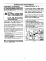
Pullguide bar forward untilchainis snug in guidebar grooves.
Now, installbar damp making sure _e adjustingpin is positionedin the lower hole in the guide bar.
Bar Clamp
Adjusting
\.......Pin J'/
..- /
Figure 41
TO CHECK CHAINTENSION:
• Use the screwdriver end ofthe bar tool to move chain around
the guidebar (Figure43).
• If chain does not rotate, it is too tight - slightlyloosen bar
clamp nuts and turn adjustingscrew 1/4 turn countemlockwise. Retightenbar clampnuts.
If chain is too loose, itwillsag below _e guidebar (Figure42).
Lower Hole
Guide Bar
Figure38
Figure 42
-22-
SERVICE
AND ADJUSTMENTS
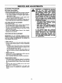
• If chain is too loose, refer to "Chain Adjustment."
Loosen bar clamp nuts; then, turn adjusting screw 1/4
turn clockwise. Lift up tip of guide bar to check for sag.
Retighten bar clamp nuts.
Notch
Pulley
Starter
Rope
Handle
Pulley
Bar Clamp
Nuts
Screw
Bar
Tool
Figure 43
STARTER ROPE REPLACEMENT
(Fig. 44, 45, 46, 47 & 48)
WARNING:
ALWAYS WEAR
EYE PROTECTION
WHEN SERVICING THE STARTER ROPE.
THE RECOIL SPRING BENEATH THE
PULLEY IS UNDER TENSION. IF THE
SPRING POPS OUT, SERIOUS INJURY
CAN RESULT.
Replace a broken starter rope or one that is badly
frayed.
NOTE: A recoil spring lies beneath the pulley and is
under tension. If the recoil spring is disturbed, considerable time and effort will be required to reinstall.
For this reason you may want to let your Sears Service
Center handle this repair. If you try to repair the starter
rope and the recoil spring pops out, take the unit to your
Sears Service Center.
Pulley Ratchet
Figure 45
• Remove the rope retainer screw and remove any
remaining rope.
• Move away from the fuel tank and melt the end of the
new rope to be installed.Allow the melted end to drop
once.Then, while the rope is still hot, pull the melted
end through a rag to obtain a smooth pointed end.
• Feed rope through starter rope hole in starter housing.
• Guide the rope inside the pulley, then up through the
pulley hole. It may be necessary to push the rope
through with a small Phillips screwdriver inserted into
the small hole on the underside of the pulley.
• Wrap rope counterclockwisearound the pulley ratchet
and tuck loose end back under rope, leaving a 1" tail
between the retainer rib and screw post.
• Pull rope to tighten.
• Install the rope retainer screw and tighten until snug.
Do not over-tighten.
• Rewind all the rope onto the pulley in a clockwise
direction.
Starter \
Housing"_k
• Remove the four fan housing screws and loosen the
two screws on the cylinder cover.
Remove fan housing from the unit.
Fan
Housing
Rope
Hole
,,Cylinder Cover Screws
II
/
\ Fan Housing
HL.. _k \
Screw
"-_"
Jl
Figure 46
• Twist and push pulley into starter housing.
Replace and tighten the pulley screw.
Screw
Rope
(Inside Fan Housing)
i
I
Figure 44
• To take out rope tension, pull out 10" of rope.While
holding down pulley ratchet with thumb, push several
inches of rope back into fan housing and catch in notch.
Either hold pulley ratchet with thumb or hold starter
rope handle. Retain rope in the notch and slowly allow
pulley to turn counterclockwise until tension is gone.
• Remove the pulley screw in the center of the pulley.
• Gently twist and lift pulley while rotating counterclockwise.
_er
o
Notch
Figure 47
-23-
o
Pulley
Screw
SERVICE
AND ADJUSTMENTS
• Pull out 10" of rope and catch rope in notchin the pulley.
• Carefully turn the pulley two complete turns clockwise,
keeping the rope against the notchto wind the spring.
• While holding the pulley ratchet, pull the excess rope
through the starter rope hole. While holding tension on
the rope, let rope slowly rewind into the housing.
• Reinstall fan housing by aligning the fan housing to
the chassis. Then while holding the fan housing
against the chassis, pull the rope handle out until you
feel the fan housing drop into place against the chassis. Slowly, let the rope rewind into starter housing.
• Reinstall the 4 fan housing screws and tighten the 2
cylinder cover screws. Fig 44.
Wind Up Spring
Figure 48
-24-
SERVICE
CARBURETOR
AND ADJUSTMENTS
ADJUSTMENTS
Carburetor adjustment Is critical and if done improperly can permanently damage the engine as well as
the carburetor. Please read all instructions and consult the Troubleshooting
section of this manual
before beginning this process.
WARNING:
THE CHAIN WILL BE MOVING DURING
MOST OF THIS PROCEDURE. WEAR
YOUR PROTECTIVE EQUIPMENT AND
OBSERVE ALL SAFETY PRECAUTIONS.
IN "LOW SPEED MIXTURE ADJUST°
MENT," RECHECK IDLE SPEED AFTER
EACH ADJUSTMENT. THE CHAIN MUST
NOT MOVE AT IDLE SPEED.
CARBURETOR
PRESETS
(Fig.
49)
If your engine will not start due to suspected improper
carburetor adjustment, the following presets may be
required. If used, it is recommended that all steps within
the adjustment procedure be completed in order to
assure a properly set carburetor. If presets are not
needed, proceed to section "Idle Speed Adjustment."
Very small adjustments can affect engine performance. It
is important to turn the screw a very small amount per
adjustment and test performance before making further
adjustments. Each adjustment should be no more than
the width of the slot in the adjusting screw.
• Turn both of the mixture screws counterclockwise until
they stop. Do not attempt to adjust the screw beyond
the stops as damage can occur.
• Turn idle speed screw clockwise 1/2 turn.
• If engine fails to start after performing carburetor presets, the unit may be flooded. Review the =Difficult
Starting" section of the manual. If problems continue
call the t-800 number listed on the front cover of this
manual for further assistance.
• Start the engine and operate for three (3) minutes to
warm up.Go to "Adjusting Procedure."
IT engine does not start, it may be flooded. If in doubt,
read the section on flooded engine in the starting section
of this manual prior to beginning any adjustments.
If you are unsure about adjusting the carburetor or experience any problem while attempting this process, please
call the 1-800 number listed on the front cover of this
manual for further assistance.
The carburetor has been adjusted at the factory for sea
level conditions. Adjustments may become necessary if
the saw is used at significantly higher altitudes or if you
notice any of the following conditions:
Idle Speed Adjustment
Low Speed
Mixture
Adj
• Chain moves when the engine runs at idle speed. See
"Idle Speed Adjustment."
• Saw will not idle. See "Idle Speed Adjustment" and =Low
Speed Mixture Adjustment."
• Engine dies or hesitates when it should accelerate. See
"Acceleration Adjustment."
• Loss of cutting power which is not corrected by air filter
cleaning. See "High Speed Mixture Adjustment."
High Speed
Mixture
Adjustment
NOTE: Your chain saw carburetor is equipped with limiter
caps. Do not attempt to adjust the mixture screws beyond
the stops as damage can occur.
Figure 49
-25-
SERVICE AND ADJUSTMENTS
ADJUSTING
PROCEDURE
CAUTION:
A CARBURETOR SETTING
THAT
IS TOO
LEAN
(CLOCKWISE
ADJUSTMENT ON HIGH SPEED SCREW
FOR MAXIMUM SPEED) WILL CAUSE
ENGINE DAMAGE TO ANY 2-CYCLE
ENGINE FROM OVERHEATING AND LACK
OF LUBRICATION. NEVER SET THE HIGH
SPEED SCREW SO FAR CLOCKWISE
THAT YOU HAVE HIGH ENGINE SPEED
LACKING POWER TO CUT. AN EFFECTIVE
APPROACH FOLLOWS.
- TURN HIGH SPEED SCREW COUNTERCLOCKWISE UNTIL ENGINE LOSES
POWER WHILE CUTTING,
- TURN HIGH SPEED SCREW CLOCKWISE USING 1/16 TURN INCREMENTS
ONLY UNTIL THE ENGINE HAS POWER
WHILE CUTTING.
IDLE SPEED ADJUSTMENT
• Allow the warm engine to idle.
• Adjust the Idle Speed Screw until the engine continues
to run without stalling and without the chain moving.
- Turn screw clockwise to increase engine speed ff
engine stalls or dies.
- Turn screw counterclockwise to slow engine down
and/or to keep the chain from turning.
• No further adjustments are necessary if chain does not
move at idle speed and if performance is satisfactory.
LOW SPEED MIXTURE ADJUSTMENT
• Allow engine to idle.
• Turn the Low Speed Mixture Screw slowly clockwise
until the RPM starts to drop. Note the position.
• Turn the Low Speed Mixture Screw slowly counterclockwise until the RPM speeds up and starts to drop
again. Note the position.
• Set the Low Speed Mixture Screw at the midpoint
between the two positions.
IF THE ENGINE DOES NOT OPERATE
ACCORDING TO THESE INSTRUCTIONS
AFTER REPEATING THE ADJUSTING
STEPS, DO NOT USE THE UNIT. FOR
FURTHER ASSISTANCE, PLEASE CALL
OUR CUSTOMER ASSISTANCE HOTLINE
AT 1-800-235-5878.
HIGH SPEED MIXTURE ADJUSTMENT
IMPORTANT: DO NOT OPERATE ENGINE AT FULL
THROTTLE FOR PROLONGED PERIODS WHILE MAKING HIGH SPEED ADJUSTMENTS AS DAMAGE TO
THE ENGINE CAN OCCUR.
• Make a test cut.
• Based on performance of the saw while cutting, adjust
the high speed mixture screw in 1/16 turn increments
as follows:
- Clockwise if saw loses power in the cut. Do not adjust
for best power by sound or speed, but judge by how
well the saw performs in the cut.
- Counterclockwise ff the saw has speed while out of
the cut, but dies in the cut or lacks power while cutting.
• Repeat the test cut.
• Continue with 1/16 turn adjustments until the saw performance is acceptable while cutting.
• After completing adjustments, check for acceleration.
ACCELERATION CHECK
• If the engine dies or hesitates instead of accelerating,
turn the Low Speed Mixture Screw 1/16 of a turn at a
time counterclockwise until you have smooth acceleration.
• Check the idle speed for stability and no chain movement. Adjust as necessary.
• Recheck for smooth acceleration and stable idle.
Repeat process as necessary for acceptable performance.
-26-
STORAGE
Immediately prepare your unit for storage at the end of
the season or if it will not be used for 30 days or more.
_
ALLOW
THE ENGINE TO COOL, AND I
ARNING:
SECURE THE UNIT BEFORE STORING
OR TRANSPORTING IN A VEHICLE.
STORE UNIT AND FUEL IN AN AREA
WHERE FUEL VAPORS CANNOT REACH
SPARKS OR OPEN FLAMES
FROM
WATER HEATERS, ELECTRIC MOTORS
OR SWITCHES, FURNACES, ETC.
STORE UNIT WITH ALL GUARDS IN
PLACE. POSITION SO THAT ANY SHARP
OBJECT
CANNOT
ACCIDENTALLY
CAUSE INJURYTO PASSERS BY.
IMPORTANT: It is important to prevent gum deposits
from forming in essential fuel system parts such as the
carburetor, fuel filter, fuel hose or tank dudng storage.
Also, experience indicates that alcohol blended fuels,
those that use ethanol or methanol (called gasohol or
oxygenated fuel), can attract moisture and form acidic
gas which will damage your engine.To avoid engine problems, the fuel system should be emptied before storage
of 30 days or longer.
Fuel stabilizer is an acceptable alternative in minimizing
the formation of fuel gum deposits during storage. Add
stabilizer to the gasoline in the fuel tank or fuel storage
container.Always follow the mix instructionsfound on stabilizer containers. Run engine at least 5 minutes after
adding stabilizer to allow the stabilizer to reach the carburetor.
STORE THE UNIT OUT OF THE REACH
OF CHILDREN.
GAS CHAIN SAW STORAGE
CRAFTSMAN 40:1 2-cycle engine oil (AIR-COOLED) is
specially blended with fuel stabilizer. If you do not use
this Sears oil, you can add a fuel stabilizer to your fuel
tank.
INSTRUCTIONS
If your chain saw is to be stored for a period of time, clean
it thoroughly prior to storage. Remove any dirt, sawdust,
leaves, oil, grease, etc. Store in a clean dry area.
• Clean the entire unit.
• Clean air filter. Refer to "Customer Responsibilities:
• Inspect the bar clamp area and clean any dirt, sawdust,
grass, or debris that has collected. Inspect the guide
bar and chain; replace a guide bar that is bent, warped,
cracked, broken, or damaged in any other way.Replace
a damaged or worn chain.
• Lightly oil external metal surfaces to prevent rust from
forming.
I_
INTERNAL
ENGINE
• Remove spark plug and pour 1 teaspoon of 40:1 2cycle engine oil (AIR-COOLED) through the spark plug
opening. Slowly pull the starter rope 8 to 10 times to
distribute oil to inner engine surfaces.
• Replace spark plug with a new one of the recommended type and heat range. Refer to =Product Specifications."
• Clean air filter. Refer to "Customer Responsibilities."
• Re-install all covers and hardware removed for access;
tighten all screws and fasteners.
• Check entire unit for loose screws, nuts, and bolts.
Replace any damaged, broken, or worn parts.
• Lightly oil external metal surface to prevent rust from
forming.
• Use fresh fuel having the proper gasoline to oil ratio at
the beginning of the next season.
handling chain. The chain is sharp and
CAUTION:
gloves
when
can cut youWear
even protective
when it is not
moving.
• Apply a coating of oil to the entire surface of the guide
bar and chain; wrap it in heavy paper, or cloth.
• Be sure all handles and guards are in place and are
securely fastened. Replace any damaged parts.
OTHER
• Do not store gasoline from one season to another.
• Replace your gasoline can if your can startsto rust.Rust
and/or dirt in your fuel system will cause problems.
• Store your unit in a well ventilated area and covered, if
possible, to prevent dust and dirt accumulation. Do not
cover with plastic. Plastic cannot breathe and will
induce condensation and eventual rust or corrosion.
FUEL SYSTEM
Never use engine or carburetor cleaner products in the
fuel tank or permanent damage may occur to fuel system
components. Follow these instructions:
• Drain the fuel from the unit into an approved fuel container.
• Drain the fuel lines and carburetor by starting the
engine and letting it run until it stops.
• Allow the engine to cool before storage.
IMPORTANT: NEVER COVER UNIT WHILE ENGINE
AND EXHAUST AREAS ARE STILL WARM.
-27-
TROUBLE
TROUBLE
SHOOTING
SHOOTING
POINTS
CHART
CORREC_ON
CAUSE
SYMPTOM
Engine will not start
or will run only for
a few seconds after starting.
1.
2.
3.
4.
5.
6.
7.
Fuel _ank empty. "
Engine flooded.
Spark plug not fidng.
Fuel not reaching carburetor.
Carburetor requires adjustment.
On/Stop Switch in =STOP" position•
None of the above.
Engine will not idle
properly.
1.
2.
3.
4.
5.
Engine will not
accelerate,lacks
power, or dies
under a load.
1.
2.
3.
4.
5.
I 6.
Engine
smokes
excessively•
1
3.
4.
5.
Idle speed set too fast or too slow.
Low speed mixture requires adjustment,
Crankshaft seals worn.
Compression low.
None of the above.
1.
2.
3.
4.
5.
6.
7.
1.
2.
3.
4.
5,
Fill tank with correctfuel mixture
See "Starting Instructions."
Install new plug/check ignitionsystem.
Replace fuel filter;inspect fuel hne.
See =Carburetor Adlustments,"
Move switch to the "ON" position.
Contact your Sears Service Canter/Dept.
See "Carburetor Ad_LJstments."
See =Carburetor Ad ustments."
Contact your Sears' 3ervica Center/Dept.
Contact your Sears Service Center/Dept.
Contact your Sears Service Center/Dept.
Air filter dirty.
Spark plug fouled.
Carburetor requires adjustment.
Exhaust ports or muffler outlets plugged•
Compression low.
None of the above.
1.
2.
3.
4.
5,
6.
Clean or replace air filter.
Clean or replace spark plug and re-gap,
See "Carburetor Adjustments."
Contact your Sears Service Center/Dept.
Contact your Sears Service Center/Dept.
Contact your Sears Service Center/Dept:.
Air
dirty.incorrect.
Fuelfilter
mixture
High speed mixture requires adjustment.
Choke partially on.
Crankcase leak.
1.
2.
3.
4.
5.
Clean or replace air filter.
Refuel with correct fuel mixture.
See -carburetor Adjustments."
Push blue choke knob in.
Contact your Sears Service Center/Dept.
1.
2.
3.
4.
5.
6.
7.
See =Fueling Your Unit."
See "Carburetor Adjustments."
Replace with correct plug•
Contact your Sears Service Center/Dept.
Clean spark arrestor screen.
Clean area.
Contact your Sears Service Center/Dept.
1. Fuel mixture incorrect.
Engine runs hot.
il
•
5.
6.
7.
Spark
plug incorrect.
igh speed
mixture set too Io,v (Lean).
Exhaust ports or muffler outlets plugged.
Carbon build-up on muffler outlet screen.
Fan housing/cylinderfins dirty.
None of the above.
Oil inadequate for
bar and chain
lubdcation.
1. Oil tank emp_.
2. Oil pump or od filter clogged•
3. Guide bar oil hole blocked.
1. Fill oil tank.
2. Contact your Sears Service Center/Dept.
3. Remove bar and clean.
Chain moves at Idle
Speed.
1. Idle speed requires adjustment.
2. Clutch requires repair•
1. See =Carburetor Adjustments."
2. Contact your Sears Service Center/Dept.
Chain does not move
when engine is
accelerated.
1.
2.
3.
4.
1.
2.
3.
4.
See =Chain Tension."
See "Carburetor Adjustments."
Repair or replace.
Contact your Sears Service Center/Dept.
Chain clatters
or cuts roughly.
1.
2.
3.
4.
1.
2.
3.
4.
See "Chain Tension."
Contact ypur Sears Service Center/Dept.
Resharpen or replace chain.
See'"Sharpening Chain."
I' Chain stops within
the cut.
Chain cuts at an
angle.
Chain tension too tight.
Carburetor requires adjustment.
Guide bar rails pinched.
Clutch slipping.
Chain tension incorrect.
Cutters damaged.
Chain worn.
Cutters dull, improperly sharpened, or
depth gauges too high.
5. Sprocket worn.
6. Chain installed backwards.
1. Chain cutter tops not filed flat.
2. Guide bar burred or bent; rails uneven.
i 3. Clutch slipping.
1. Cutters damaged on one side.
5. Contact your Sears Service Center/Dept.
6. Install chain in rightdirection.
1. See "Sharpening Chain."
2. Repair or replace guide bar.
3. Contact your Sears Service Center/Dept.
1. See "Sharpening Chain•"
2. See "Sharpening Chain."
3. Replace guide bar.
I 2. Chain dull on one side.
3. Guide bar bent or worn.
If s#uations occur which are not covered in this manual, use care and good judgement.
ff you need assistance, contact your SEARS Service Center/Department or the
CUSTOMER ASSISTANCE HOTLINE at 1-800-235-5878.
-28-
REPAIR PARTS
SEARS
MODELS
358.351141
AND 358.351061
61
I
66
41
33
34
65
Ref.
Part
No.
2.
3.
4.
5.
6.
7.
8.
530-047818
530-015701
530-037809
530-037803
530-015917
530-047989
530-038406
530-047831
9.
530-094188
L
I0. ] 530-047061
II.
12.
13.
14.
15.
16.
17.
18.
19.
20
22.
530-015611
530-014949
530-038227
530-016149
530-047819
530-015922
530-029850
530-015905
530-015907
530-016109
530-069611
Description
Ref.
Part No.
Description
Trigger - Throttle
Pin
W_re - Throttle
Cover - Clutch
23.
24.
26.
28.
29.
30.
31.
32.
33.
34.
35.
36.
530-038238
530-069698
530-038543
530-037818
530-016064
530-019206
530-038241
530-038373
530-037821
530-030189
530-015775
530-069216
38.
530-047192
Plate - Bar Mounting
Kit Oil Pump
Gear Assy
Body - Oil Pump
Screw. Oil Pump
Block - Seal
Fitting - Elbow
Pick-Up Tube
Filter - Oil
Plug - Oil Filter
Screw
Kit - Fuel Line
(Large Dia.)
Assy - Fuel Cap
w/Retainer
Bolt - Bar
Gasket Kit
(- Indicates contents
also on following pg.)
Screw
Bolt
Screw
Pin - Dowel
Worm Gear
Handle - Front
Nut - Bar Mounting
Lever - Choke
Grommet - Choke Knob
Assy - Chassis
(incl. 36, 37, 38, 40,
41.62, 63, 64, [29 &
31 from page 30])
Spring Clutch
Assy - Clutch Drum
w/Brg
Washer - Clutch
Assy - Clutch
Lever - Switch
41.
530-016133
530-069608
42.
43.
44.
45.
46.
47.
530-016020
530-016132
530-015905
530-016138
530-037820
530-037799
_0.
Spring - Switch
Lock-out
Clip - Cyl Shield Screw
Chain Catcher
Screw
Washer - Thrust
Pin - Bar Adjusting
Kit- Bar Adjusting
- 29 -
Ref.
Part No.
Description
48.
49.
50.
51.
52.
53.
54.
55.
56.
57.
58.
530-038224
530-015940
530-037485
530-069232
530-015892
530-037816
530-027531
530-037817
530-039187
5304.00897
530-092322
59.
60.
61.
62.
63.
64.
65.
66.
530-016134
530-015920
530-016080
530-026119
530-038264
530-010846
952-706606
71-3617
71-3629
71-36365
71-36366
Handguard
Screw
Handle - Starter
Kit - Rope
Screw
Hsg - Fan
Spring - Recoil
Pulley - Starter
Assy - Flywheel
Washer - Flywheel
Lock Washer Flywheel
Nut - Flywheel
Screw - Pulley
Screw - Rope Anchor
Check Valve
Plug - Oil Vent
Assy - Oil Cap
Chain Brake Kit
Chain- 14"
Chain - 16"
Bar- 14"
67.
Bar-
16"
REPAIR PARTS
SEARS MODELS 358.351141 AND 358.351061
16
30
1\
34
36
37
25
35
42
Ref. Part No.
I.
2.
3.
4
5.
7.
8.
9.
I0.
II.
IZ
13.
14.
15,
530-083950
530-037793
530-016101
530-037804
530-069703
530-015810
530-037806
530-016094
530-016153
530-037798
530-038318
530-038317
530-038340
530-047566
Description
Operator's
Manual
Air Filler - Foam
Nut - Carb Screw
Hs 8 - Air Filter
Carburetor Kitw/
Limiter Caps
(#12 & 13)
Screw
Adapter - Cacb
Screw
Screw
Shield -Cyl
Limiter Cap - High
Limitar Cap - Low
Grommet - Carb Adjust
Assy - Primer
Ref.
Part
No.
16.
530-069247
18.
20.
21.
530-030154
530-069606
530-069604
22.
23.
24.
25.
26.
27,
530-029805
530-015697
530-047062
530-047179
530-037935
530-016136
28.
30.
530-016090
530-047834
Description
Fuel Line Kit
(Small Dia)
Spark Plug
Cylinder - Machined
Piston Kit (incl. 22, 23,
Piston & Wrist Pin)
Ring - Piston
Retainer - Piston Pin
Assy - Crankshaft
Assy - Seal & Bearing
Cap - Crankcase
Clip - High Tension
Lead
! Screw
Assy - Wire Harness
- 30 -
Part No.
Description
3 I.
32.
34.
35.
530-014362
530-037652
530-038237
530-047207
Fuel Filter Assy
Insulator - Heat
Back Plate - Muffler
36.
3Z
38.
39.
40.
41.
42.
530-037245
530-036103
530-016132
530-039167
530-015905
530-047442
530-069608
43.
530-038253
Ref.
Assy - Muffler (incl.
36, 37 & 38)
Diffuser - Muffler
Screen - Spark Arrestol
Screw
Ignition Module
Screw
Strap - Ground
Gasket Kit
(. Indicates contents
also on previous P8-)
= Decal Instruction
(not shown)
REPAIR PARTS
SEARS
MODELS
358.351141
AND 358.351061
Carburetor Kit #530-069703
Ref.
I.
2.
3.
l
2
I
t
I
3
-31 -
Part No.
Description
530-038318
530-038317
530-035399
Limiter Cap - High
Limiter Cap - Low
CarburetorRepair Kit
(* Indicates Contents)
CRRFTSMRN
Operator's
Manual
2.2 cu, inJ36cc 2-CYCLE
14 Inch Guide Bar
16 Inch Guide Bar
GASOLINE CHAIN SAW
Model No.
358.351141
358.351061
Each Gasoline Chain Saw has its own model number. The model
number for your unit will be found on a decal attached to the unit.
IF YOU NEED REPAIR
SERVICE OR PARTS:
REPAIR SERVICE
1-800-4-REPAIR
(1-800-473-7247)
ORDERING PARTS
1-800-FON-PART
(1-800-366-7278)
All parts listedherein may be ordered through Sears, Roebuck and
Co. Service Center and most Retail Stores.
WHEN ORDERING REPAIR PARTS, ALWAYS GIVE THE FOLLOWING INFORMATION
• PRODUCT-
"GASOLINE CHAIN SAW"
• MODEL NUMBER - 358.351141
358.351061
• PART NUMBER
• PART DESCRIPTION
Your Sears merchandise has added value when you consider that
Sears has service units nationwide staffedwith Sears trained technicians.., professional technicians specifically trained on Sears
products, having the parts, tools and the equipment to insure that
we meet our pledge to you, we service what we sell.
HOURS (CST)
Mort.- Sat. 7a.m.- 7 p.m.
Sun. 10 a.m.- 7p.m.,
Seam, Roebuck and Co., Hoffman Estates, IL 60179 USA