1
S. A/k S
CRIIFrgMltN
MODEL NUMBER 917.256450
•
°
•
•
°
OWNER'S
MANUAL
Assembly
Operation
Customer Responsibilities
Service and Adjustments
Repair Parts
CAUTION: Read and follow all safety rules and instructions before operating this equipment.
FOR CONSUMER ASSISTANCE HOT LINE, CALL THIS TOLL FREE NUMBER_ 1-B00-659-5917
[I '1
L_
_.
""_1_:
IIIIIIIIIIIIIIIIIHIIIHIIIIIIIIIIIIII
,,,,,,,,,,,
,,,
,,,,,,,,
II
,,,,,,,,,,,,,,,,,,,,,,,,,,,,,,,,,,,,
IIII I
,
I
I
.......................
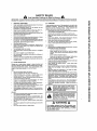
SAFETY RULES
Safe Operation Practices for Ride-On Mowers
IMPORTANT; THIS CUTTING MACHNE tS CAPABLE OF AMPUTATING HANDS AND FEET AND THROWtNG OBJECTS
FA]LIJRE TO OBSERVE THE FOLLOWING SAFETY INSTRUCTIONS COULD RESULT IN SERIOUS iNJURY OR DEATH..
L
GENERAL
•
Read, understand,
end fotlcw a_l InstrUctions in the manual
and on Ihe machine belore stad{ng
Only allow responsible
aduils, who are tamiUar with the
Instructions, to operate the machine
Clear the area of objects such as rocks, toys, wfre_ etc,
which could be picked up and thrown by the blade
Besurethearealsclearofotharpeoplabeforamawing
Stop
machine if anyone enters the area
Never carry passengers
Do not mow in reverse unless abselulely necessary Always
took down and behind belora and while backing
Be aware ot the mower discharge dlractton and de not point
It at anyone,
Do not operate the mower w_lhoal either the
entire grass catcher or the guard in place
Stow down before turning
Never leave a running machine unattended,
Always turn off
b_ades set parking brake, stop engine, and remove keys
before d smountlng
Turn off blades when not mowing
Stop engine before removing grass catcher or unclogging
chute ...........
Mow only in daytlght or good artificial light
Do not operate the machine while under the Influence of
alcohol or drugs
Watch lot Ira{tic when operating near or crossing roadways
Use extra care when loading or unloading the machine In{o
a traitor or truck
•
•
•
.
•
•
•
•
•
,
"
.
II.
OPERATION
SLOPE OPERATION
Stopes are a major factor related to loss-of-control and
Upover accidents which can result in severe injury or death.
All slopes require extra caution, f you cannot back up the
slope or if you feeluneasy on It, do not mow it
DO:
•
Mow up and down slopes, not across
•
Remove obslacles such as rocks,tree _imbs,elc
•
Watch for holes, ruls, or bumps. Uneven terratn could
overturn the machine Taft grass can hide obstacles,
•
Useslow speed Choose a tow gear so that you wtttnot have
to stop or shift white on the slope.
•
Follow the manufacturer's recommendations for wheel
weights or counlerwalghts to improve stebiltly,
•
Use extra care with grass catchers or other attachments
These can change the stability of the machine
,'
Keep all movement on the slopes slowend gradual Do not
make sudden changesin speed or direction
•
Avoid starting or stopping on a slope. If tires lose traction,
disengage the b_adesand proceed slowly slraigh! down the
slope
DO NOT;
•
Dono/turn on slopesunless necessary, andthen-turn slowly
and gradually downhill, tl posstb[s
,
Do not mow near drep-oJfs, ditches, or embankments The
mower could suddenlyturn over if a wheel {s over the edge
el a cliff or ditch, or an edge caves in
•
Do net mow on wet grass Reduced traction could cause
sUdtng
•
Do not try to slabiiize the machine by puttingyour foot on the
ground,
•
Do not use grass catcher on steep slopes.
ii1, CHILDREN
Tragic accidents can occur if the operalor ts not alert to the
presence of children
Children are often atlraeted to Ihe
machine and the mowing activity.
Never assume that
children will remain where you last saw them
•
Keep children out of the mowing area and underthe walchful
care of another responsibleadult
•
Be clad and turnmachine off i{children enter the area
•
Before and when backing, look behind and down for small
cbitdran
•
•
•
Never carry children, They may, fa!_ off and be seriously
injured or interfere wilh safe machJne operation
Never allow chiidranto operate the machine
Use extra care when approaching blind corners, shrubs,
trees, or otherobjects that may obscure vision
IV. SERVICE
Usa extra carein handling gasoline and otherfuels They are
Ilammabla and vapors are explosive
Use only an approvedcontainer.
NBVB_"
femow gas cap or add luel with the engine
running Allowengine to coot before refueling Do not
smoke,
Never refuel the machine indoors,
Never store the machine or fuel containerInside where
there is an open flame, such as a water heater
Never run a machine inside a closed area
Keep nuls andbolts, especially blade attachment bolts, tight
and keep equipmentingood condIlion
Never tamper with safety devices
Check their proper
operallonregularly,
Keep machine Irae el grass, feaves, or olher debrts build=up.
Clean oil or fuel spiUage. Allow machine to cool before
storing.
Stop and Inspect the equipment tf you strike an obiect
Repair. If necessary, before rastading,
i
Never make adjustments or repairs with the engine running.
i
Grass catcher componentsare subjectIo wear, damage, and
dalerioratlon which could expose moving pads or aUow
objects to be thrown. Frequently check components and
replace withmanufacturer's recommendedparis, when necessary
Mower blades are sharp snd can cut Wrap the blade(s) or
wear gloves, and use extra caution when servicing them
Check brake operation frequently Adjust and service as
required
Look for this symbol
to point out Im-
CAUT|ONtl]
YOUR
portent safetyBECOMEALERTII1
precautions,
it means
SAFETY IS INVOLVED.
"' cAuT!oN'; Alwa'y; disconnect "parkpiug
wire and place wire where It cannot contact
spark plug in order to prevent accidental
starting when setting up, transporting,
13.
O
iii
09
nO
LI.
O3
ILl
.J
O3
(9
Z
-I-
(9
N
O3
nO
ii
UJ
I::1
l
(3
P
!
I
I
I
, ad "s"ng,,°",ma,k,l,n
,,,I,,r?pairs"
O3
LU
(5
C9
O9
& WARNING
The engine exhaust
from this product
contains cnemmam
Known to the State of Californla to cause cancer, birth defects,
or other
reproductive
harm,
n.H,n
uJ
,,,,.H,,,
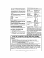
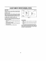
CONGRATULATIONS
on your purchase of a Sears
Tractor. I1 has been designed, engineered and manufactured to give you the best possible dependability
and
performance.
Should you experience any problem you cannol easily
remedy, please contact your nearest Sears Authorized
Service CentedDepadment
We have competent, welltrained technicians and the proper tooJa to service or repair
this tractor
Please read and retain this manual
The ]nstructlons will
enable you to assemble a nd maintain your tractor prope dy
Atways observe the "SAFETY RULES".
MODEL
NUMBER
917.256450
PRODUCT
SPECIFICATIONS
HORSEPOWER:
12 5
GASOLINE CAPACITY
AND TYPE:
5 QUARTS
UNLEADED REGULAR
OIL TYPE (API,.SFtSG):
SAE 30 (above 32'_F)
SAE 5W-30 (below 32°F)
OIL CAPACITY;
3 0 PINTS
SPARK PLUG:
(GAP: 030")
CHAMPION RJtgLM
STD 361458
VALVE CLEARANCE:
INTAKE:
005" - 007"
EXHAUST: 009" - 01 t"
GROUND SPEED (MPH):
FORWARD:
let
2rid
3rd
4th
5th
REVERSE:
SERIAL
NUMBER
DATEOFPURCHASE
THEMODELANDSERIALNUMBERSWILLBEFOUND
TIRE PRESSURE:
FRONT: 14 PSI
REAR:
12 PSi
CHARGING SYSTEM:
3 AMPS BATTERY
5AMPSHEADLiGHTS
BATTERY,,
AMPiHR:
25
CASE SIZE:
U1R
ON A PLATE UNDER THE SEAT_
YOUSHOULDRECORDBOTHSERIALNUMBERAND
DATE OF PURCHASE AND KEEP IN A SAFE PLACE
.FOR.FUTU RE_REFERENCE, L_
MAINTENANCE
AGREEMENT
BLADE BOLT TORQUE:
A Sears Maintenance Agreement Is available on this product Contact your nearest Sears store for dela[ls
CUSTOMER
RESPONSIBILITIES
,
Read and observe the safety rules
•
Fellow a regular schedule tn r'nalntainlng, caring for and
using your tractor
•
Follow the instructions under"Customer
Responsibilities" and "Storage" sections of this owner's manual
LIMITED
ONE YEAR
WARRANTY
I 0
I 3
2 1
3 1
40
16
30-35 FT. LBS.
WARNING:
This tractor is equipped with an Internat
combustion engine and should not be used on or near any
unimproved forest-covered; brush-covered
or grass-covered land unless lhe engine s exhaust system is equipped
with a spark arrester meeting applicable local or stale laws
(if any) if a spark arrestor is used, it should be maintained
in etfeclive working order by the operator.
In the stale of CaJifomia the above is required by taw
(Section 4442 of the California Public Resources Code)
Other sEates may have similar laws Federal laws apply on
federal Jands A spark arresler for the muffler is available
through your nearest Sears Authorized Service Center/
Depadment (See REPAIR PARTS section of this manual
ON CRAFTSMAN
RIDING
EQUIPMENT
For one {1) year from the date of purchase, [tIbis Crallsman Riding Equipmentis ma_ntained__ubricaled and Iuned up according
le the instructionsin the owner's manual, Sears wil!repair or replace, tree of charge, any parts found to be defective in metedal
or workmanship
This Warranty does not cover:.
"
Expendable Hems which become worn during normal use, such as b_ades,spark plugs,air cleaners, belts, efc
Tire replacement or repaircaused by punctures from outside objects, suchas nails, thorns, stumps, or glass.
',
Repairs necessary' because of operator abuse, neg]igence, improperslorage or accident or the faiture to mainlaln the
equipment according IoIhe lnstrucltonscontained In the owner's manual
•
Riding equipment used for commercialor rental purposes,
LIMITED
90 DAY WARRANTY
ON BATTERY
For ninety (g0} days from daie of purchase, tf any battery Included wilh this riding equipment proves defeclive in material or
workmanshipand our testingdelerrnlnes lhe battery will not hold a charge,Sears wltJreplace the balfery al no charge
IN-HOME WARRANTY SERVICE ON YOUR CRAFTSMAN RIDING EQUIPMENT ESAVAILASLE AT NO-CHARGE FOR 30
DAYS FROM THE DATE OF PURCHASE PLEASE CONTACT YOUR NEAREST SERVICE CENTER. AFTER 30 DAYS
FROM THE DATE OF PURCHASE, WARRANTY SERVICE 1SAVAILABLE BY TAKING YOUR CRAFTSMAN RIDING EOUIPMENT TO YOUR NEAREST SEARS SERVICE CENTER. (IN-HOME WARRANTY SERVICE WILL STILL BE AVAILABLE
AFTER 30 DAYS FROM THE DATE OF PURCHASE BUT A STANDARD TRiP CHARGE WiLL APPLY) THIS WARRANTY
APPLIES ONLY WHILE THIS PRODUCT IS iN THE UNITED STATES
This Warranty gives you specillc legal rights, and you may also have other rights which may vary Item state tostate
SEARS, ROEBUCK
AND CQ, D/817 WA, HOFFMAN ESTATES,
IL 60179
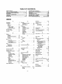
TABLE
OF CONTENTS
SAFETY RULES ............................................................
2
PRODUCT SPECIFICATIONS
........................................ 3
CUSTOMER RESPONSIBILITIES
..................... 3, 14-18
WARRANTY ......................................................................
3
TRACTOR ACCESSORIES ...................................................5
ASSEMBLY ................................................................
7-9
OPERATION ..............................................................
t0-13
MAINTENANCE SCHEDULE ........................................ 14
SERVICE AND ADJUSTMENTS
................................ 19-24
STORAGE .....................................................................
25
TROUBLESHOOTING
...........................................
26-27
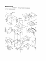
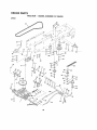
REPAIR PARTS - TRACTOR .................................... 30-47
REPAIR PARTS - ENGINE ...................................... 48-52
PARTS ORDERINGtSERVICE
............... BACK COVER
INDEX
A
Accessories ..............................
Adjustments:
Brake ..................
.............
Carburetor ...................
Mower
Front-To-Back .......................
Side-To-Side .....................
Throltte Control Cable ................
Air Filler. Engine ..........................
Air Screen. Engine .......................
Assembly .........................................
E
5
21
24
20
20
23
17
17
7-9
Operation
Btectdcel:
Interlocks end Relays ............
23
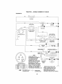
Schematic .......................
29
Wiring Diagram ...................
30
Engine-'
A_rFilter..............................
17
Air Screen .............................
17
Cooting Fins, Engine ..............
17
Oil Change ...........................
16
0t) Level .........................
12,18
Oil Type ................................
16
Preparation ...........................
12
Repair Pads ......................... 46.52
Starling ......................................
13
................................
t0-t3
Operating Mower
....................
12
Options:
Accessories ...... ...................
.,, 5
Spark Arrestor ...................
3,40
P
Parking Brake
10-11
Parts Bag .......................................
6
Pads, Replacement/Repe)r ........ 30-47
Producl SpecilicalJens
3
.........................
........................
R
Repair Parts_;;;=;:=:=:,-o=:':::;:=_;:;::::
:-30-47.....
..................................
Storage :,:':::_;:;:;:::"; "_:.':,L :;:.:LC,: 25
..........
B_ille_i_
..............
Charging ................................
6
S
F
CIeanlng ...................................
16
Starling wilh Weak Battery ......... 22
Salary Rules ...............................
2
Filter:
£1orage ...........................
25
Seat ............
........................ .., 8
Air Filler ..............................
17
Terminals
16
Fuel ............................
18
Belt'.
Motion Drive
Removal!Replacement
........
21
Mower Btade(s)
Removal/Replacement
.....
21
Blade:
Sharpening .....................t5
Replacement .........................
I5
Brake Adjustment
....................
21
FueI:
Type ................................
Slerage ...............................
12
25
FUSe
23
.......................................
H
Hood Removal/Inslaliatton
............... 23
L
C
Leveltng Mower Deck .....................
Lubrication:
Carbureler Adjustment .................
24
Chad ................................
Controls, Tractor ........................
t0
Customer Responsibilities.......... 15.t 8
Engine:
AlrFilter,,,,,.,,
, ..........
17
Air Screen, Engine .................. 17
CooIing Fins, Engine .............. t7
Engine OIl ............................
t6
Fuel Filter ..............................
18
Spark PLug(s) ................
18
Traclor;
Batlery ........................................ 16
Blade ................................
15
LubricationChad ................... 14
Maintenance Schedule ........... I4
Tire Care ...................
8,t5,22
T_-ansaxle ...............................
16
Curling HeighL Mower ...................
11
20
14
M
Maintenance Schedule
Service and Adjustments ..........
19-24
Carburetor ............................
24
Fuse ..........................................
23
Hood Re movalllnstallation ....... 23
Motion Ddve Bell
Removal/Replacement
,21
Mower Belt(s)
RemovatfReplaoement ....
21
MoWer Adjustment
Front-to-Back
. ..............
20
S_de-to-Side ........................
29
Mower Removal ....................
19
Tire Care .........................
6,!5,22
Slope GUide Sheet ......................
51
Spark Plug(s) ............................
18
Speclflcalions
Binding the Engine ..................
12-!3
Steering Wheel ..........................
7,22
Stopping the Tractor
1t
Storage ...........................................
25
................................
............
14
Mower:
3
Adjustment, Frent..to-Back ....... 20
Adjuslmenl, Side-to-Side ......... 20
Blade Sharpening .................
15
Blade Replacement....................
15
T
Cut.LingHelghl.....................
11
_nstalfatlon................................
f9
Throttle
Conlmt Cable Adjustment ...... 24
Operation ..............................
12
Tires
Removal .......................
19
Trouble Shooting Chad ................ 26-27
Mowlng Tips
t3
Transaxie ....................................
16
Mutfter ............
18
Spark Arrestor ......................
3,40
W
..................
......................................
8)15,2
_
..........................
.....................
O
OI!:
Cold Weather Conditions ......
Engine
......................
Storage ....................
t2)16
t6
25
Warranty ...............................
Wiring Dlag<am ...............................
Wiring Schematic ......................
3
30
29
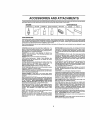
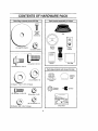
ACCESSORIES AND ATTACHMENTS
Those accessories and attachments were available through meal Sears retail outlets andserVice centerswhen thetractorwas purshased
Most Sears stores can order these items for you when you provide the model number el your tractor.
ENGINE
SPARKPLUG
MAINTENANCE
GAS CAN
ENGINEOIL
FUEL STABILIZERi
AIR FILTER
BLADES
BELTS
t
PERFORMANCE
Sears oilers a wide varietyo! attachmentsthat tit your tractor, Many of these aye tisted betswwith briel expianaIions of how theycan help
you. Thislist was current at Ihe lime of pubEtcation;
however, it may change in future years - more altachments may be added, ctlanges
may be made In these altachments or some may nolonger be available or tltyear model Contact your nearest Sears store for the
accessories and attachments thai are eva lab e for your tractor.,
Most el Ihese attachments do not require additional httchesor conversion ktls (lhose that do are iedicaled) and are designed tot easy
atlachtng and detaching.
AERATOR pr0motesdeep root growth tot a healthy Iawn Tapered 2.5-inch steel spikes mounted on 1O-tnchdiameter discs
punclure holes in soil at close intervals to tel moisture soak in
.Steel welghf tray for Increased penetration.......................
BAGGER lets you collect grass clippings and leaves tot a
hsallhlar, nearer looking lawn Two Permanex containershard
3g-gallon plastic bags
BUMPER prelects front end of lraclor from damage
CARTS make hauling easy, Variety o1[sizes available, plus
accessories such as side panel kils, toot caddy, cad cover,
prolactive mat and deity
CORING AERATOR takes small plugs out ef soil to allow roofslure and nuldents to reach grass roots 36-Inch swath 2¢
hardened steel coringtips 150 lb.,capacity weighl tray
EASY OIL DRAIN VALVE makes oil changes easier, faster
FRONT NOSE ROLLER canters in front el mower deck to reduce
chances of "scalping" on uneven terrain
GANG HITCH lets you low 2 or 3 pul_-behindatlachmenls al once,
suchas sweepers, dethatshers,aerators (not (or use withtoilers.
cartsor other heavy attachments)
GAUGE WHEELS on bolh sides of the mower deck reduce
chancesof "scalplng" on uneven terrain For mower decks not so
equipped,
MULCH RAKE./DETHATCHER loosens soil andflips thatch and
matted leaves to lawn surface for easy pickup,Twenty springttne
teeth Uselul Ioprepare bare areas forseedlng. Available forfront
or rear mounting. HIGH PERFORMANCE REEL*ACTION
SPRING TINE DETHATCHER covers 36-inch wide palh and
tosses thalch Inlo large hopper_ Mounts behind tractor.
MULCHING CLOSE-OUT PLATE KIT, once tnslalled,lets you
mulch, discharge or bag clippings (bagger optional) without
changingblades For models not equippedas 3-1n-1 Convertible
mowers
See "MOWER" In the Repair Parts eeclion of Ihis
manual
RAMP TOPS AND FEET tat youtoad and unload tractor from a
pickup Iruck Use with 2 x 8 or 2 x 10 lumber
ROLLER for smoother tawn surface. 36-inch wide, 18-Inch
dtamelerwaler-gght drum hotds up to3g0 Ibs.ofweight. Rounded
edges prevent harm to tuff Adjustable scraper automattsalty
cleans drum
SNOW B LADE Ior snow removal only. 14-Inch high, 48-inch wide
btede clears 42-Inch pathwhen angled loft or right Raises, lowers
with side lever Ad}ustebJe skids; replaceable, reversible scraper
.bar, (Usewtthtirechainaaedwheetweightsandlo_reardrawbar
weight )
SNOWTHROWER
has 4g-Inch swath, Drum-type auger handles
powdery and weUheavy snow
Mounts easily with simple pin
arrangement
Dlschargechule
adjusts Item traclor seat. 6-inch
diameter spout discharges snow 10 Io 50 Ieef, UtI controlled al
tractor seat. (Use with chains and wheat weights end!or rear
drawbsr wetghl )
SPRAYERS use 12-volt DO elecldc motor that connects to the
tractor baltery or other |2-volt source.
Includes booms for
automatic spraying and hand held wand ler spot spraying. Wand
has adjustabts spray paltem.
For applying herbicides, insecli cides, lungtcides and iiquld fediUzers.
SPREADER/SEEDERS
make seeding, ledttizing, and weed killing easy, Broadcast spreaders are also usetul for granular de.,
leers and sand.
SWEEPERS
let you collect grass clippings
and leaves
TILLER has 5 hp engine and 36-,inch swath to prepare seed beds=
cultivate and compost garden residue
Tiller has its own butlt-in
lift and depth conlrol system and does NOT require a sleeve hitch.
Fitsanytawn, ysrdorgardenlrae!or.
Simply hook up to the tractor
drawbar
and gel
Optional
accessories
convert unil for
dethatshing,
aerating, hiIling without tools,
TIRE CHAINS are heavy duty; eloseiy spaced extraqarge
!inks give smooth dale, outstanding Iraction
cross
TRACTOR
CAB has heavy duly vinyl labdc over tubular sleel
frame, ABS plastic fop; clear plastic windshield offers 360 degree
visibility Hinged metal doors with catch. Keeps operatorwarm
and dry Remove vinyl sides and windshields for usa as sun
protector _n summer, Optional
accessories
tnclude:
tinted/
tempered solid safely glass windshield w_thhand operated wipe_
12-veil amber caution Itght for mounting on cab top
VACS Ior pawedul collection of heavygrass
clippings and ieaves,
Optional
wand attachment
to pick up debds In hard-to-reach
places
VACICHIPPER
Includes a chipper-shredder
WEIGHT BRACKET for drewbar
Uses (f) 55 tb weight
Ior snow removal
WHEEL WEIGHTS let rear wheels provide needed
snow removat or dozing heavy matodala
applications
Iraction
for
CONTENTS
OF HARDWARE
i,u,,,u=,u,
PACK
, i lll
,
H=
H
IIIlU=
Parts packed separately in carton
(2) Sheet
Metal
Screws
#10-16 x 1/2
Seat
Steering
Whee!
(1 ) Large Flat Washer
(1} Locknut
3/8-24
Video
Cassette
Steering
Boot
Parts Bag
Manual
(1) Hex Boll 1/2-13 x 1
(1) Shoutder Bo}t 5/16-18
Parts bag contents not shown full size
Wheel
Steering
Insert
%___
(1) Lock Washer
(1) Washer
1/2
Steenng Wheel
Adapter
17/32 x 1-3/16 x 12 Gauge
(@
(2) He× Bolts
(2) Keys
Bushing
teedng
1/4-20 x 3/4
(2) Hex Nuts 1/4-20
(2) Lock Washers
(2) Washers
, uu, u
9/32
t/4
Slope Slteet
x 5/8 x 16 Gauge
,
i.i ...............
,
,
,,
,,,n,
= i i,
i
i
ASSEMBLY
Your new tractor has been assembied at the factory with exception of those paris left unassembled for shipping purposes
To ensure safe and proper operation of your tractor all parts and hardware you assembb must be tightened securely Use
the correct toots as necessary to insure proper tightness,
TOOLS
REQUIRED
FOR
ASSEMBLY
A socket wrench set wit! make assembly easier
wrench sizes are listed.
Standard
(1) 5/16" wrench
(1) 9/16" wrench
(2) 7/16" wrenches
Tire pressure gauge
(1) 1/2" wrench
Utilib7 knife
(1) 3/4" wrench
When right and left hand are mentioned
means when you are in the operallng
behind the steering wheel)
TO REMOVE TRACTOR
UNPACK
in this manual, it
position (seated
FROM CARTON
CARTON
•
Remove a!l accessible loose parts and paris cartons
from carton (See page 6),
•
Cut along lines on carton, from top to bottom, afl four
corners of carton and Iay panels fiat
•
Check for any edditlonaJ loose parts or cartons
remove.
BEFORE ROLLING TRACTOR
STEERING
SHAFT
POSITION)
and
STEERING
SHAFT
{SHIPPING
; ...."*--.
POSmO.) "-.......::::::::.......," ."
OFF SKID
•
Slide the steering bushing over the steedng shaft.
•
Raise steering shaft forward unlif screw hobs In dash
line up with steering bushing.
Install two (2) sheet
metal screws and tighten securely
•
Position steering boot oversteefing
•
Align tabs of steering boot over slots and hole in dash
and push down to secure
•
•
Slide steering wheel adapter onto upper steering shaft
Position trent wheels of the tractor so they are pointing
straight forward,
•
Position steering wheel so cross bars are horizontal
(tel| to right) and sfide onto adapter.
°
Assemble large flat washer and 3/8-24 hsxlocknut
tighlen securely.
•
Snap insert into center of steedng wheel,
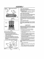
CONNECT BATTERY (See Figs. 2 and 3)
CAUTION:
Do not short battery terminals. Before connecting battery, remove metal
bracelets,
wristwatch
bands, rings, etc.
shaft
Positive terminal must be connected
first to prevent sparking from accidental grounding.
Remove cardboard packing from seat pan and lift seat
pan to raised position
•
Open battery box door
•
Remove terminal protective caps and discard.
•
ff this battery is put into service after month and year
Indicated on label (label located between terminals)
charge battery for minimum of one hour at 6-t0 amps
•
First connect RED battery ca hie to positive (+) terminal
with hex bolt, llal washer, lock washer and hex nul as
shown. Tighten securely.
•
Connect BLACK grounding cable to negalive (-) terminal with remaining hex bolt, fiat washer, lock washer
and hex nut. Tighlen securely.
•
Close battery box door_
Open battery box door for:
',
Inspection for secure connections (to lighten hardware).
"
Inspection [or corrosion.
•
Testing battery.
°
Jumping (if required),
and
'.
Remove protective ptastlc from tractor hood and grill,
IMPORTANT:
CHECK
FOR AND REMOVE
ANY
STAPLES iN SKID THAT MAY PUNCTURE TIRES WHERE
TRACTOR tS TO ROLL OFF SKID
OFF SKID (See Fig. 5)
•
Raise atlaohment
lift lever to tts highest posilion.
•
Release
pedal,
brake by depressing
,,
•
Place gearshift lever in neutral (N) position,
Roll tractor backwards off skid
•
Remove banding holding discharge guard up against
tractor.
parking
SLOT
FIG. 1
ATTACH STEERING WHEEL (See Fig. 1)
TO ROLL TRACTOR
TAB
t
clutch/brake
7
"
Periodic charging
ASSEMBLY
POSmVE
{RED)CABLE
DISCARDTERMINALPROTECTIVE
CAPS
HEX
CHECK
TIRE
PRESSURE
The tires on your tractor were ovednflated
shipping purposes. Correct tire pressure
best cutting pedormanCe,r
Reduce tire pressure to PSi shown
SPECIFICATIONS"
on page 3 of this
LOCK
WASHER
FLAT
NASHER
at the factory for
is importanl for
in "PRODUCT
manual,
CHECK DECK LEVELNESS
For best cutting resul!s, mower housing should be properly
teveJed, See "TO LEVEL MOWER HOUSING" in the
Service and Adjustments section of this manual
CHECK FOR PROPER
POSITION
OFALL
BELTS
See the figures that are shown for replacing motion and
mower blade drive baits in the Service and Adjuslments
section of this manual° Verify that the belts are fouled
oorreetly.
NEGATIVE
(BLACK}CABLE
FIG. 2
CHECK BRAKE SYSTEM
After you learn how to operate your tractor, check to see
that the brake is properly adjusted.
See "TO ADJUST
BRAKE" in the Service and Adjustments section of this
manual
SEAT
PAN
,I CHECKLIST
BEFORE YOU OPERATE
AND ENJOY YOUR NEW
TRACTOR, WE WISH TO ASSURE THAT YOU RECEtVE
THE BE ST PERFORMANCE AND SA TISFA C TtON FROM
THIS QUALITY PRODUCT_
BATTERY
BOX DOOR
PLEASE REVIEW THE FOLLOWING
v" AIt assembly instructions
FIG, 3
INSTALL SEAT (See Fig. 4)
Adjust seat before tightening adjustment bofL
•
Remove cardboard packing on seat pan.
•
Place seat on pan and assemble shoulder boll.
,,
Assemble adjustment bo]t,tock washer and flat washer
loosely Do not tighten.
,,
Tighten shouIder bolt securely.
•
Lower seat into operating position and sit on seat.
•
Slide seat until a comfortable position is reached which
allows you to press clutchtbrake pedal eli the way down
(See Fig. B)
Get off seat without moving its adjusted position.
Raise seat and tighten adjustment bolt securely.
v"
No remaining loose pads in carton.,
,/
Battery is propedy prepared and charged,
1 hour at 6 amps).
(Minimum
,/
Seat is adtusted comfortably and tightened
securely,
,/
AIi tires are properly Inflated. (For shipping purposes
the tires wore overmI ated at the factory).
v"
Be sure mower deck is properly leveled side.to-side/
front-to*rear for besl cutting results. (Tires must be
properly inflated for leveling)r
.!
Check mower and drive belts. Be sure they are routed
properly around pulleys and inside el! belt keepers,
,/
Check wiring, See that all connections
and wires are properly clamped.
,t"
"\
are still secure
WHILE L EARNING HOW TO USE YOUR TRACTOR, PAY
EXTRA A TTENTION TO THE FOLL OWING IMPORTANT
ITEMS:
SEAT_
S_OULOER
CHECKLIST:
have been completed.,
. \\ \L-_.\ \"
Engine oil Isat proper level
,,," Fuel tank is filled with fresh, clean, regular unleaded
gasoline.
_\\
v"
Become famitiar with all controls - their Iocatlon and
function, Operate them before you start the engine.
V" Be sure brake system is in safe operaling
/
'_'_
FLATWASH_R
FIG. 4
B
condition.
OPERATION
These symbols may appear on your tractor or in lilerature supplied wilh the producl
Learn and understand
their meanlng
1:::3,& ,
BATTERY
CAUTION OR
WARNING
REVERSE
FORWARD
PAST
SLOW
ENGINE ON
ENGINE OFF
OIL PRESSURE
CLUTCH
LIGHTS ON
LIGHTS OFF
FUEL
CHOKE
MOWER
HEIGHT
DIFFERENTIAL
LOCK
PARKtNG BRAKE
LOCKED
UNLOCKED
L
REVERSE
MOWER
LIFT
NEUTRAL
ATTACHMENT
CLUTCH ENGAGED
HIGH
LOW
ATTACHMENT
CLUTCH DISENGAGED
HYDROSTATIC
DANGER,
KEEP HANDS AND FEET AWAY
PARKING
BRAKE
IGNITION
FREE WHE EL
(Hydro Models only)
OPERATION
KNOW
YOUR
TRACTOR
READ THIS OWNER'S MANUAL AND SAFETY RULES BEFORE OPERATING YOUR TRACTOR
Compare the iifustrations withyour tractor to familiarize yourself with the locations of various contrets and adjustments.
this manual for future reference
ATTACHMENT
CLUTCHLEVER
LIGHTSWITCH
Save
iGNiTION
SWITCH
L FTLEVER PLUNGER
ATTACHMENT
LIFT LEVER
THROttLE/CHOKE
CONTROL
CLUTCHIBRAKE
PEDAL
MOWER DECK
HEIGHT ADJUST-
PARKING BRAKE
GEARSHIFT '
LEVER
FIG, 5
Our tractors conform to the safety standards of the American
A'I-rACHMENT
mower blades,
[rector.
LIGHT SWITCH:
CLUTCH LEVER: Used to engage Ihe
or other attachments
mounted to your
GEARSHIFT
treclor.
Used for starting
and
Locks
clutch/brake
pedal
Seiectsthe
speed and direction of
LIFT LEVER PLUNGER; Used to release attachment
tever when changing its position
CLUTCWBRAKE
PEDAL: Used for declutchtng and braking the tractor and starting the engine.
PARKING BRAKE:
brake position
LEVER:
Institute
ATTACHMENT
LIFT LEVER; Used to raise, lower and
adjust the mower deck or other attachments mounted to
your traclor,
Turns the headtlgh!s on and off
THROTTLE/CHOKE
CONTROL:
controlling engine speed,
National Standards
IGNITION SWITCH:
engine
into the
10
Used for starling and stopping
lift
the
OPERATION
The operation of any tractor can result in foreign objects thrown into the eyes, which
can result In severe eye damage, Always wear safety glasses or eye shields while
operating your tractoror performingany adjUstments or repairs. We recommend a wide
vision safety mask over the spectacles or standard safety glasses_
,i,illlll,,ll,llll
,
ill llll
i
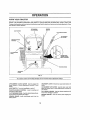
HOW TO USE YOUR TRACTOR
TO MOVE FORWARD AND BACKWARD
(See Fig, 6)
TO SET PARKING BRAKE (See Fig. 6)
Your tractor is equipped with an operator presence sensing
switch, • When engine is running, any attempt by the
operator to leave the seat without first selling the parking
brake wiif shut otf the engine.
The direction and speed o{ movement
gearshift lever.
•
Depress crutch/brake
and hold.
pedal into futJ "BRAKE" position
',
Place parking brake lever in "ENGAGED" posftion and
releasepressurefromclutchfbrakepedaf
Pedalshouid
remain In "BRAKEI' position Make sure parking brake
will hold tracloi" secure.
•
Start tractor with ctulch/brake pedal depressed
gearshift lever in neutral (N) position,
•
Move gearshift
lever to desired
MOWER BLADES
position,
ATTACHMENT CLUTCH LEVER
"ENGAGED" POSITION
o
Move attachment
sition.,
GROUND
and
•
Slowly release clutch/brake pedal to start movement
IMPORTANT: BRtNGTRACTOR
TOACOMPLETE
STOP
BEFORE SHIFTING OR CHANGING GEARS. FAILURE
TO DO SO WILL SHORTEN THE USEFUL LIFE OF YOUR
TRANSAXLE.
STOPPING (See Fig. 6)
•
is controlled by the
ctutch lever to "DISENGAGED"
poPARKING BRAKE
POSITION
DRIVE -
,,
Depress clutch/brake pedal into full "BRAKE" posilion,
•
Move gearshift lever to neutrat (N) position,
ENGINE "
GEARSHIFT
LEVER
Move throttle control to slow (,w_) posffion,
NOTE;
Failure to move throttle control to Stow (-_)
position and allowing engine to idle before stopping may
cause engine to "backfire".
•
Turn ignition key to "OFF" position and remove key.
Always remove key when leaving tractor to prevent
unauthorized use,
•
Never use choke to stop engine.
FIG, 6
NOTE: Under certain conditions when tractor ts standing
idle with the engine running, hol engine exhaust gases may
cause "browning" of grass, To eliminate Ihis possibility,
always stop engine when stopping tractor on grass areas
J A ,Ik
[ _
l- P_.
M
TO USE
pfetefy, asdescribedabove,
beforeteav.
tog the operator's
position; to empty
CAUTION:
Always stop tractor c0mgrass catcher, etc.
THROTTLE
TO
Atways operate engine at full threltle.,
•
Full throttle offers the best bagging and mower performance.
CUTTING
HEIGHT
fill lever determines
lhe
•
Grasp lift lever.
•
Press plunger with thumb and move lever to desired
position,
Thecutting height range is approximalely 1-tt2 to 4". The
heights are measured from lhe ground to Ihe blade tip with
the engine not running
These heights are approximate
and may vary depending upon soil conditions, height el
grass and types of grass being mowed
CONTROL (See Fig. 6)
Operating engine at tess than full throttle reduces the
battery charging rate
MOWER
The position of the attachment
culling heighl
,,,t
•
ADJUST
(See Fig. 5)
11
.
The average lawn should be cut to approximately 2- t/2
inches during the cool season and to over 3 Inches
during hot monlhs
For healthier and belier looking
lawns, mow often and after moderale growth.
•
For best cutting performance, grass over 6 inches in
hefght should be mowed tw{ce, Make the first cut
relatively high; the second to desired height.
,,
,,,i,,
i
=
OPERATION
TO OPERATE MOWER (See Fig, 7)
Your tractor is equfpped with an operator presence sensing
switch. Any attempt by the operator to leave lhe seat with
the engine running and the attachment clutch engaged wttl
shut elf the engine.
,,
•
blades by engaging
TO STOP MOWER BLADESclutch control
attachment
To restart movement, slowly release parking brake and
clutchforake pedaf
•
Make all turns slowly
TO TRANSPORT
Select desired height of cut.
Start mower
control
.
•
Raise attachment
ment Wt control,
,,
When pushing orfowing your tractor, be sure gearshilt
lever is in neutral (N) position,
"
Do not push or tow tractor at more than live (5) MPH_
clutch
disengage attachment
,,
',HH H,, H,
NOTE: To protect, hood from damage when transporting
your traclor on a truck or atraiter, be sure hood is closed and
secured to tractor,, Use an appropriate means of tying hood
to tractor (rope, cord, etc ).
without either the entire grass catcher,
CAUTION;
operate or
the the
mower
on
mowers Do
so not
equipped_
discharge guard in place°
BEFORE
ATTACHMENT
"DISENGAGED"
CLUTCH
LEVER
POSITION
CHECK
"ENGAGED _ POSITION
LEVER
lift to highest position with attach-
HIGH POSITION
STARTING
ENGINE
OIL
THE ENGINE
LEVEL
(See Fig. 12)
*
The engine in your tractor has been shipped, fromthe
,,
Check engine oil with tractor on levet ground.
•
Remove oil fill cap/dlpstick and wipe clean, reinsed the
dipstick and screw cap tfghl, wait for a few seconds
remove and read oil level
if nece_,sary, add ot! unti
"FULL" mark on dipstick is reached, Do not cvertiiL
,,
For cold weather operation you should change oil for
easier starting (See "OIL VISCOSITY CHART" in the
Customer Responslbilities see!ion of this manual).
.
To change engine oil, see the Customer
ties section in this manual.
,/
LOW
POSmON
ResponsibilF
ADD GASOLINE
Hr
RUNNER
•
Fill _uer tank,
Use fresh, clean, regular unleaded
gasoline with a minimum of 87 octane, (Use of leaded
gasoline wiit increase carbon and lead oxide deposits
and reduce valve life), Do not mix oil with gasoline.
Purchase fuel in quantities that can be used within 30
days Io assure fuel freshness+
IMPORTANT:
WHEN OPERATING IN TEMPERATURES
BELOW 32_F(0°C), USE FRESH, CLEAN WINTER GRADE
GASOLINE TO HELP INSURE GOOD COLD WEATHER
STARTING,
GUARD
FiG, 7
TO OPERATE ON HILLS
,
i
hills with elopes greater
t
than 15_ and
CAUTION:
Do not drive up or down
de.ofdrlve"Cro__
s_'opo.
ny
._
_'
Choose the slowest speed before starling up or down
hills.
•
Avoid stopping or changing
•
If slowing is necessary,
slower position,.
°
if stopping Is absofuteJy necessary, push clutch/brake
pedal quickly to brake position and engage parking
Drake.
•
WARNING:
Experience indicates that aIcohol blended
fuels (called gasohol or using ethanol or methanol) can
altracl moisture which leads to sepm atlon and formation of
acids during slorage.
Acidic gas can damage the fuel
syslem of an engine while in storage. To avoid engine
problems, the fuel system shoutd be emptied before star.,
age of 30 days or _onger, Drain the gas tank, start the
engine and let 11run until the fuel tines and carburetor are
empty. Use fresh fuel next season. See Storage Instructions for addittonaJ information,
Never use engine or
carburetor cleaner products in the fuet tank or permanent
damage may occur.
,L,
speed on hitls.
move throttle control lever to
1........
CAUTION:
Fill to
filler necko Do not
spilled oil or fuel,
use gasoline near
Move gearshift lever to 1st gear. Be sure you have
allowed room for fraclor to roll slightly as you restart
movement
t2
bottom of gas tank
overfill, Wipe off eny
DO not store, spill or
an open flame,
!
OPERATION
TO START
ENGINE
(See Fig. 6)
When starting engine for the first time or If engine has run
out of fuel, it witl take extra cranki0g time to move fuel from
the tank to the engine
•
Depress clutch/blake
°
Place gearshift lever In neutrai (N) pesltlqn°
,,
Move attachment
•
Move th[ottle control lever to choke (}"l) position for
coid engine start For warm engine start, move throttle
Centre1 t o fast (,_) posi!ion
•
insert keyinto Ignition and turn key clockwise to"START"
position and refease key as soon as engine starts. Do
nel run starter conttnuousfy for more than fifteen
seconds per minute, If engine does not start after
several attempts, move throttle control to last (._)
position wait a few minutes and try again°
•
.,
pedal and set parking brake
clutch to "DISENGAGED
When engine starts
position.
minutes
before
NOTE: if at a high altitude (above 3000 feet) or in cold
temperatures
(below 32°F) the carburetor fuel mixture
may need to be adjusled [orbest engine performance See
TO ADJUST CARBURETOR"
in the Service and Adjustments section of this manual
MOWING
'
When mowing large areas, start by turning to the right
so that c[ipplngs will discharge away from shrubs,
fences, driveways, arc Alterone or two rounds mow
in the opposite direction making left hand turns until
finished (See Fig 8)
"
tf grass is extremely tall, it should be mowed twice to
reduce load and possible fire hazard from dried clip
pings Make first cut re[ativeJy high; the second to the
desired height
•
Do not mow grass when it ts wet Wet grass will plug
mower and leave undesirable clumps
Allow grass to
dry before mowing
•
Always operate engine at lull throtfle when mowing to
assure belier mowing performance
and proper dis
charge of material Regulate ground speed by se[ect
ing a low enough gear to give the mower culling
performance as well as the quality of cut desired
that will suit the terrain and give best performance
the atlachment being used,
f
TIPS
•
Tire chains cannot be used when the mower housing
_sallached to tractor
•
Mower should be properly leveled for best mow!,ng
performance See TO LEVEL MOWER HOUSING in
the Service and Adjustments section of this manual
•
Use the rUnner on the right hand side of mower as a
guide The blade cuts approximately an inch outside
Ihe runner (See Fig 7)
The left hand side of mower should be used for trimruing
•
Drive so that clippings are discharged onto the area
that has been cut Have the cut area to the right of the
machine This wIH result in a more even d_stdbution of
clippings and more uniform cutting
position
move throttle conifer to desired
Aflow engine to warm up for afew
....engaging drive or attachments=
•
J
FIG 8
13
of
CUSTOMER
MAINTENANCE
SCHEDULE
_/_//,
Check
B,o,o
Ope,a,e.
V'
V'
CheckTirePressure
rT
RESPONSIBILITIES
R
C
T
SharpenlReptaceMswe_Blades
LubricationChart
Check BatteryLeveltRecharge
0
Clean Battery and Tefminqt_
R
CheckTt,ansaxleCooling
AdjuBl
Blade Bell(s) Tension
V"
v'
v'
Checkfor LooseFastener's
,_ ,_/_'_
_
V',
_v"
v"
'ii0'
v',
u ==Hu
Check Engine O!!Level
Change Engine Oil
V_
t
V Iv"
CleanAir Filter
I
_v".......
Adjusl MotionDrive Belt(s) Tensioe
,
......
it"
v"
,,
{
I •
........................
Iv'
....
__e_
v"
v'2
i.......
!i._ .........................
-C!,ea.
A_S_ _.............
............... .........
_G
I
Inspect MufflertSparkAtteSter
ReplaceOil Filter(11equippedl
..... v"
= Replase
Sp_ Pl,,g
v" v"
___
ReplaceAir FtI|erPaperCarltidge
v'_V'
ReplaceFuel Filter
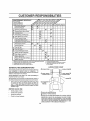
GENERAL
LUBRICATION CHART
RECOMMENDATIONS
The warranty on this tractor does not cover items that have
been subjecled 1o opera_or abuse or negligence,
To
receive fu_lvalue from the warranty, operator must maintain
tractor as Instructed in this manual
Some adjustments wilt need Io be made periodically
properly maintain your tractor.
®
(_)
to
®
All adjustments tn the Service and Adjustments section of
this manual should be checked at least once each season.
•
Once a year you should replace the spark plug, clean
or replace air tilter, and check blades and bells for
wear. A new spark plug and clean air filter assure
proper air..|uet mixture and hefp your engine run better
andlast longer
BEFORE
EACH
I
CLUTCH
PIVOT[S)
USE
•
Check engine oil ]evet,
•
Check brake operation,
•
Check tire pressure,
•
Check forloose
(_ SAE30 OR laW30 MOTOROIL
(_} GENERALPURPOSEGREASE
(_ REFERTO CUSTOMERRESPONSIB1L(TtES
"ENGINE" SECTlBN
fasteners
_MPORTANT: DO NOT OtL OR GREASE THE PIVOT POtNTB
WHICH HAVE SPECIAL NYLON BEARINGS VISCOUS LUBRtCANTSWILL ATTRACT DUST AND DIRT THAT WILL SHORTEN
THE LfFE OF THE SELF-LUBRICATING
BEARINGS. tF YOU
FEEL THEY MUST BE LUBRICATED, USE ONLY A DRY, POWDERED GRAPHITE TYPE LUBRICANT SPARINGLY
14
CUSTOMER RESPONSIBILITIES
TRACTOR
AJways observe
nance.
safety ru+es when performing
any mainte-
BLADE
MANDREL
BRAKE OPERATION
if traclor requires more than six (6) feet stopping distance
at hfgh speed in highest gear, then brake must be adjusted.
(See "TO ADJUST BRAKE" in the Service and Adjustment s section of this manuel).
TRAILING EDGE
FLAT WASHER _.
TIRES
.
'Maintain proper air pressure in oil tires (See "PRODUCT SPECiFiCATIONS
on page 3 of this manual}
•
Keep tires free of gas0tfne, ott, or insect control chemicals which can harm nJbber+
•
Avoid stumps, stones, deep ruts, sharp objects and
other hazards that may pause !ire damage
HEX BOLT
(GRADE B)* _.,_
"A GRADE B HEAT TREATED BOLT CAN BE
IDEHTIRBD BY SiX LrNES ON THE BOLT HEAD.
FIG., 9
BLADE CARE
...........For bes+t.re.suits mow+er+blades .must bB..kept.sharp=Re=
place bent or damaged btades.
....
Raise mower
blades*
•
Remove hex boll, lock washer and flat washer securing
blade+
•
Install new or resharpened
towards deck as shown
*
Reassemble hex bolt, lock washer and flat washer in
exact order as shown.
,,
Tighten bol! securely (30-35 Ft. Lbs. torque)
IMPORTANT:
R PE NBEADE-(S_Fig-.-10}
...............
Care should be taken to keep the blade balanced.
An
unbalanced blade will cause excessive vibration and eventuai damage to mower and engine
BLADE REMOVAL (See Fig. 9)
-
TO SHA
to highest position to allow access to
,,
The blade can be sharpened with a Iite or on a grinding
wheel Do nel attempt to sharpen while on the mower
•
To check btade balance, you will need a 5/8 " dlamet er
steel bolt, pin, or a cone balancer (When using a cone
batancer, follow the instructions supplied with balancer)°
•
Slide blade on to an unthreaded per, ion of the steel bolt
or pin and hold the bolt or pin parallel wilh the ground.
If blade fs balanced, it should remain in a horizontar
position- If either end of the blade moves downward.
sharpen the heavy end until the blade is balanced
blade with trailing edge up
BLADE BOLTIS GRADE 8 HEATTREATED
NOTE: We do not recommend sharpe nlng blade - but if you
do, be sure the blade is balanced.
NOTE: Do not use a naif for balancing blade. The lobes or
the center hole may appear to be centered, but are not.
CENTERHOLE
5/8" BOLT
_
/
/
+_,_
BLADE
!:t
F|G, "lO
15
CUSTOMER RESPONSIBILITIES
BATTERY
ENGINE
Your tractor has a batlery charging system whtch is sufficient for normal use. However, periodic charging of the
batlery with an automotive charger will extend ils life
,
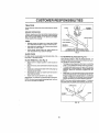
LUBRICATION
Only use high quality detergent oil raled wilh API service
classlficallon SF or SG Select the oii's SAE viscosity grade
according to your expected operating temperature.
Keep battery and terminals clean
',
Keep battery bolts tight
•
Keep small vent holes open.
•
Recharge at @10 amperes for I hour
TO CLEAN BATTERY AND TERMINALS
_F
Corrosion and dirt on the battery and terminals can cause
lhe battery to "lea_' power.
[
•
Remove terminal guard.
•
Disconnect BLACK battery cable first then RED bat..
lery cabfe and remove battery from tractor.
,,
Rinse the battery with plain water and dry.
•
Clean terminals and batterycable
until bright.
Coal terminals
......................
-2D'
0"
TEMPERATURE
3_t"
40"
RANGE At_ICJPATED
_o"
80"
'
_139"
SEFORE NEXT OiL CHANGE
J
F|G. 11
NOTE: Although mufti-viscosity oils (5W30, 10W30 elc)
improve starting In cold weather, these multi-viscosity oils
will result in increased oii consumption when used above
32°F. Check your engine oil level more frequently 1oavoid
possible engine damage from running'low on oil
ends with wire brush
with grease or petroleum jelly,
Change the oil after the first two hours of opera! on and
Assembly section oT tnls manua_
tr actor is not used for 25 hours in one year
Check the crankcase etI level before starting the engine
and after each eight (8) hours of operation. Tighten oil fill
cap/dipstick securely each lime you check the oll level.
V-BELTS
CheckV-belts for deterioration and wear alter 1O0hours of
operation and replace if necessary The belts are not
adjustable. Replace bells if theybegin Io slip from wear,
TO CHANGE
ENGINE OIL (See Figs. 11 and 12)
Determine temperature
TRANSAXLE
_.b
COOLING
range expected before oil change,
All oil must meet APf service classif!qalion
.
Be sure tractor is on level surface.
Keep transaxie free from build-up of dirt and chaff which
can restrict coeling,1
SF or SG
•
,
Oir will drain more freely when warmCatch oil in a suitable container,
•
Remove oft fit! cap/dlpstick. Be careful not to allow dirt
to enter the engine when changing oil,
•
Remove dratn plug,
•
Affer oil has drained completely,
and tighten securely.
•
Refill engine wilh otl through oi_tilt dipstick tube. Pour
slowly. Do not overfill. For approximate capacity see
"PRODUCT
SPECIFICATIONS
on page 3 ofthts
manuaJ
,,
Use gauge on oil fill cap/dipstick tor checking level. Be
sure dipstick cap is t_ghtaned securely for accurate
reading. Keep oil at "FULL" fine on dipstick.
replace oil dra{n plug
_AP/DIpSTICK
OIL DRAIN
PLUG
16
FIG, 12
CUSTOMER RESPONSIBILITIES
•
ii
,
ii
I,IH,
II
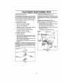
AIR FILTER (See Fig. 13)
CLEAN AIR SCREEN (See Fig. 14)
Your engine will not run propedy using a dirty air filter
Cle,_n the foam pre-cleaner after every 25 hours of operation or every season. Service paper cartridge every 100
hours of operation or every season, whichever occurs first
Air screen must be kept free ol dirt and chaff to preven!
engine damage from overheating. Clean with a wire brush
or compressed air 1o remove dirt and stubborn dried gum
fibers,
Service air cleaner
more often under dusty conditions
ENGINE COOLING FINS (See Fig.
•
Remove knob(s) and cover.
TO SERVICE PRE-CLEANER
14
Remove any dust, dirt or oil from engine cooling lins to
prevent engine damage lrom overheating
,
Slide foam pre-cleaneroff
cartridge
•
Wash it in liquid detergent
and water,
,
•
Remove screws from blower housing and lift housing
and dipstick tube assembly off engine
Squeeze it dry in a clean cloth,
•
Cover oil fill opening
Saturate it in engine oit, Wrap it in clean, absorbent
clolh and squeeze to remove excess oil
•
Use compressed air or stiff bristle brush to thoroughly
clean engine cooling fins..
•
If verydfrty or damaged, reptaee pro-cleaner
,
To reassemble,
•
Reinslall
•
Reinstai[cover
•
TO SERVICE
•
pre-cleanerover
reverse above procedure
cartridge
SCREWS
and secure wilh knob(s)
BLOWE R HOUSING
CARTRIDGE
SCREWS
Remove cartridge nut.
feting carburetor,
Clean base carefully
debris from entering carburetor,
•
to proven1 entry of dirt
to prevent
Cleancartfidgebytappinggenttyonflatsurface
dirty or damaged, replace cartridge.
livery
AIR SCREEN
DIPSTICK TUBE
ASSEMBLY
•
Reinstall cartridge, nut, precleaner, cover and secure
with knob(s)
IMPORTANT=
PETROLEUM
SOLVENTS,
SUCH AS
KEROSENE, ARE NOT TO BE USED TO CLEAN THE
CARTRIDGE
THEY MAY CAUSE DETERIORATION OF
THE CARTRIDGE
DO NOT OIL CARTRIDGE
DO NOT
USE PRESSURIZED
AIR TO CLEAN
OR DRY
CARTRIDGE
PLUG
DOVERKNOB _"_
ENGINECOOLINGFINS
F1Gs14
OARTRIDGENUT
FOAr,
PRE-CLEANER""_
PAPER
CARTRIDGE
_
FIG. 13
17
CUSTOMER
RESPONSIBILITIES
MUFFLER
Inspect and replace corroded muffler and spark arrestor (if
equipped) as it could create a firehazard and!or damage.
SPARK
PLUGS
Replace spark plugs at the beginning of each mowing
season or after every 100 hours ot operation, whichever
OCCURS
first. Spark plug type and gap setting are shown in
"PRODUCT SPECIFICATIONS*'
on page 3 of this manual.
I
c
IN-LINE FUEL FILTER (See Fig. 15)
CLAMP
FIG. 15
The fuel filter should be repiacedonce each season If fuel
filter becomes clogged, obstructing fuel flow to carburelor,
replacement is required
cool, remove
CLEANING
•
With engine
sections
filter and plug fuel line
•
•
Place new fuel filler in posflton in rue! line with arrow
pointing towards carburetor
Clean eng!ne, batte_,
matter.
•
•
Be sure there are no fuet fine leaks and clamps are
properly positioned
Keep finished surfaces and wheels free of all gasoline,
o11,elc.
•
Protec! pa!nted suflacesw!th
,
Immediatety wipe up any _pilled gaso_the
....
seat, finish, etc. of all foreign
"au!omotivetype
y_ax_.
We do not recommend using a garden hose to clean your
tractor unless the electrical system, rnuflfer, air filter and
carburetor are covered to keep water out Water tn engine
can resutt in a shodened engine life.
18
SERVICE AND ADJUSTMENTS
CAUTION;
&
•
BEFORE
PERFORMING
Depress clut_:Wbrake
ANY SERVICE
OR ADJUSTMENTS:
pedal fUlly and set parking brake,
Place attachmerit
In "DISENGAGED"
Place
gearshlftleverclutch
in neutral(N)
position.
Turn ignition key "OFF" and remove key,
position,
-
Make sure the blades and all moving parts have completely
*
Disconnect
plug,
spark plug wire from sParkplug
stopped.
and place wire where it cannot come in contact with
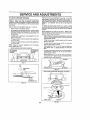
TO REMOVE MOWER (See Fig. 16)
CLUTCH
Mower will be easier to remoye from the rig ht side of tractor
•
Place attachment
•
Move attachment tilllever forward Io lower mower to its
lowest position.
clutch in "DISENGAGED"
ROD
LEVER
position.
•
Roll belt off engine pulley.
•
Disconnect clutch rod from clutch tever by removing
retainer spring
,.
Disconnect asti-sway, bar from chassis :bracket by
removing retainer spring
•
DiscOnnect suspension arms from rear deck brackets
by removing retainer springs
•
Disconnect front links from deck by removing retainer
springs
,.
Raise lift lever to raise suspension
out from under tractor
RI_TAINERSPR!NGS
arms. Slide mower
IMPORTANT;
fF AN ATTACHMENT OTHER THAN THE
MOWER DECK IS TO BE MOUNTED ON THE TRACTOR.
REMOVE THE FRONT LINKS
TO INSTALL MOWER (See Fig. '16)
•
Raise attachment _tt lever to IIs highest position.
•
Slide mower under tractor with discharge guard to right
side of tractor,
•
•
ANTI-SWAY
Lower Iift lever to Its lowest position,
installmower In reverse order of removal instructions,
19
BAR
FIGo 16
..........._..................................
m
SERVICE AND ADJUSTMENTS
=,l,i
i,= ,H,=
Ill
II=l=
TO LEVEL MOWER HOUSING
FRONT-TO-BACK
Adjust the mower while tractor ts parked on level ground or
driveway.
Make sure tires are properly inflated (See
"PRODUCT SPECIFICATIONS"
on page 3 of this manuaI).
Ifttresare over or undednflated
you wlfl not properly adjust
your mower
IMPORTANT:
DECK MUST BE LEVEL SfDE-TO-S1DE IF
THE FOLLOWING FRONT-TO-BACK ADJUSTMENT
iS
NECESSARY, BE SURE TO ADJUST BOTH FRONT LINKS
EQUALLY SO MOWER WtLL STAY LEVEL SIDE-TO,,
SIDE,,
SIDE-TO-SIDE
ADJUSTMENT
Raise mower to its highest position
•
At the midpoint of both sides of mower, measure height
Irom bottom edge of mowerto ground. Distance"A" on
both sides of mower shoutd be the same or within 1/4"
of each other.
,
If adustment is necessary,
side of mower on y.
•
,
make adjustment
(See Figs
19 and 20)
TO obtain the best cutting results, the mower housing
should be adjusted so thai the front is approximately 1t4" to
3/4" lower than the rear when the mower is in its highest
position,
(See Figs, 17 and 18)
•
ADJUSTMENT
Check adjustment on right side of tractor, Measure dislance"D" directly in front and behind the mandrel al bottom
edge of mower housing as shown
"
To ratse one side of mower, tighten lift link adjustment
nut on thai side.
Before making any necessaryad ustments, check that
both front finks are equaltn length Bothllnks shouldbe
approximately t0_3/8".
"
To lower one side of mower, loosen lilt link adjustment
nut en that side.
If links are not equal in length, adjust one link to same
length as other link
•
To lower front of mower loosen nut "E" on both front
links an equal number of turns
•
When distance "D" is 1/4" to 3/4" lower at front than
rear, tighten nuts "F" against trunnion on both front
ttnks_.................................................
',
To raise front ef mower, loosen nut "F"lrom trunnion on
both front links. Tighten nut "E" on both front links an
equal number of turns
•
When distance "D" is 1/4" to 3/4" tower at front than
rear, tighten nut"F" against trunnion on both front links
NOTE: Three full turns of adlustment
mower height about 1t8",
on one
nut will change
...Re._checkmeasurements.a_fter, adjqs tng ...................
BOTTOMEDGE
OF MOWERTO
GROUND
BOTTOMEDGE
OF MOWERTO
GROUND
Recheck side-lo-side
_., _'_:_,_,
adjuslmen!.
I
_'_! ..." MANDREL
FIG. t7
SUSPENSION
ARM
FIG. 19
BOTH FRONT LINKS MUST BE EQUAL IN LENGTH
LIFT LINK
ADJUSTMENT NUT
FIG. 18
NUT "E"
FRONT LINKS
20
TRUNNION
FIG. 20
SERVICE AND ADJUSTMENTS
i
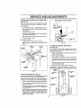
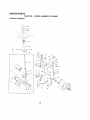
TO REPLACE MOWER BLADE DRIVE BELT
(See Fig, 21)
WITH PARKING
BRAKE
"ENGAGED"
The mower blade drive belt may be replaced without tools_
Park the tractor on Ievel surface
Engage parking brake,
BELT REMOVAL
-
•
Place attachment
•
Move attachment lift lever forward to lower mower to its
[owesl position
•
Roit bert off engine pulley.
•
Disconnect R H, suspension armlrom reardeck bracket
by removing retainer spring,
,,
Work belt off both mandrel pulleys and idler pulleys,
•
Pull belt away from mower
BELT INSTALLATION
clutch in "DISENGAGED"
position
NUT "A"
_E
AM
NUT
RATING
ARM
•
Install new belt in reverse order of removal
•
Make sure belt is in all pulley grooves and inside all belt
guide&
......
MANDREL
IDLER
PULLEYS
.....
FIG. 22
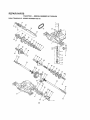
TO REPLACE MOTION DRIVE BELT ......
(See Fig. 23)
ENGINE
PULLEY
Park the tractor on level surface, Engage parking brake
For assistance, there is a belt _netaltation guide decal on
bottom side of fell footrest
SUSPENSION
ARM
•
Remove mower (See ,,TO REMOVE
section of Ihis manual )
MOWEH
•
Remove upper belt keeper
•
Remove belt from stationary idler and clutching idler
Pull bell stack toward rear of tractor
Remove belt
upwards from transaxle pulley by deflecting
ers.
SPRING
•
". Ibis
belt keep-
Pull belt leward front of tractor and remove downwards
from around engine pulley
.
install new beFt by reversing above procedure
iMPORTANT:
MAKE SURE UPPER BELT KEEPER IS
POSITIONED PROPERLY BETWEEN LOCATER TABS
ENGINE_--44..__
--
tl
FIG. 21
CLUTCHING
_,_'_,_*"f
II
TABS
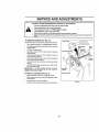
TO ADJUST BRAKE (See Fig. 22)
tl
Your tractor is equipped with an adjustable brake system
which Is mounted on the right side of the transaxte
MPf
STATIONARY_ |l
Depress clutch/b rake pedal and engage parking brake
•
Measure dislance between brake operating arm and
nut "A" on brake rod.
_,
ltdistancefsotherthan
1q/2", ioosenjamnutandturn
nut "A" until dislance becomes 1-1/2". Retighten jam
nut against nut "A'L
*
Road test tractor for proper stopptng distance as stated
above, Read ust if necessary. If stopping distance fs
stlii greater than six (6) feet in highest gear, further
maintenance is necessary. Contact your nearest authorized service center
_t
1
|
tr ,_ UPPER
t
II
!
TRANSAXLE.
21
II
I
_
FIG, 23
BELT
II KEEPER
" II ll Ii
If tractor requires more than six (6) feet stopping distance
at high speed in highest gear, then brake must be adjusted
•
jtto.);
II
,,i,,u,,,,i, LIu,, ,,,i i,,
,
,,
SERVICE AND ADJUSTMENTS
TO ADJUST STEERING WHEEL
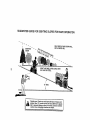
TO START ENGINE WITH A WEAK BATTERY
(See Fig. 25)
ALIGNMENT
{f steering wheel crossbars are not horizontal (left to right)
when wheels are positioned straight forward, remove steering wheel and reassemble per instructions in the Assembly
section of this manual
FRONT
CAUTION:
Lead-acid batteries generateexp|ostvegases,
Keep sparks,llame
and smoking materials away from batteries.
Always wear eye protection
when around batteries°
TOE-IN/CAMBER
WHEEL
The front wheel toe-An and camber are nol adjustable on
your tractor
if damage has occurred to affect the front
wheel toe-in or camber, contact your nearest authorized
service center
TO REMOVE
WHEEL
FOR
II your battery is Ioo weak to start the engine, il should be
recharged.
If "jumper cables" are used ior emergency
starting, follow this procedure:
REPAIRS
IMPORTANT: YOUR TRACTOR iS EQUIPPED WiTH A 12
VOLT NEGATtVE GROUNDED SYSTEM
THE OTHER
VEHICLE
MUST ALSo BE A 12 VOLT NEGATIVE
GROUNDED SYSTEM. DO NOT USE YOUR TRACTOR
BATTERY TO START OTHER VEHICLES
(See Fig° 24)
•
Block up axle securely.
•
Remove axle cover, retaining ring and washers 1oallow
wheel removal (rear wheel contains a square key - Do
net lose)
TO ATTACH
JUMPER CABLES -
•
Connect each end of the RED cable Io the POSITIVE
(+) terminal of each battery, taking care not to short
againsl chassis_
•
Repair tire and reassemble.
•
On rear wheels only: align grooves in rear whee! hub
and axte, Insert square, key:.
•
•
Replace washers and snap retaining
axle groove
.Connect.one.end_of the.BLACK cable to.Ihe..NEGA-_._
T/VE (-) lerminal of fully charged battery.
,,
,
Replace ax}e cover
Connect the other end of the BLACK cable fo good
CHASSIS GROUND, away from fuel tank and battery
dng securely in
TO REMOVE CABLES,
WASHERS
RETAINING
RING
_'SQUARE
REVERSE ORDER -
•
BLACK cable first lrom chassis and fhen from the fully
charged battery
°
RED cable last from both batteries
POSITIVE TERMINAL
NEGATIVE TERMENAL
POSITIVETERMINAL
NEGATIVETERMINAL
KEY
(REAR WHEEL ONLY)
FIG, 24
FIG, 25
22
SERVICE AND ADJUSTMENTS
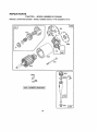
TO REPLACE HEADLIGHT
BULB
* Raise hoOd.r
. PuIt bulb holder out of the hole in Ihe backside of the
grill.
° Replace bulb in holder and push butb hoider securely
back into the hole in the backside of the grill
.
Close hood
ENGINE
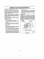
TO ADJUST THROTTLE
(See Fig, 27)
The throttle control has been preset at the faclory and
adjustment should not be necessary Check adjustment as
described below before loosening cable If adjustment is
necessary, proceed as tollows:
INTERLOCKS
AND RELAYS
Loose or damaged wiring may cause your tractorto run
poorly, stop running,or prevent it Irom starting.
• Check wiring See electrical wiring diagram fn Repair
Parts section of thismanual.
TO REPLACE
FUSE
,'
With engine not running, move throttle control _ever
from stow (.e_)'to choke (I\l) position. S{owly move
lever from choke (N) to fast (,_,) position
,,
Checkthat _oles"A" in g0vernorcontroJtever
and hole
in governor plate llne-up, t_ holes A' are not aligned,
loosen clamp screw and move throttle cabte until holes
are aligned Tighlen damp screw securely
Replace with 30 amp automotive-type plug-,Infuse The
fuse holder is locatedbehind the dash°
TO REMOVE HOOD
..(S.ee_ig.26)
•
Raise hood_
•
•
"
AND GRILL
CONTROL CABLE
GOVERNOR
CONTRGLLEVER
GOVERNOR
CONTROLPLATE
ASSEMBLY
Unsnap headlight wire connector.
Stand in front of Iractor.Grasp hoodat sides, tilt toward
engine and lift off of tractor,
To replace, reverse aboye procedure.
HOOD
\
ROLES "A"
CLAMP
SCREW
FIG. 27
HEADLIGHT
._
WIRE
CONNECTOR
FIG. 26
23
THROTTLE
CABLE
SERVICE AND ADJUSTMENTS
, .................
, ,,
u
TO ADJUST CARBURETOR (See Fig. 28)
ACCELERATION
The carburetor has been preset at the factory and adiuslment should not be necessary.
However, minor adjustment may be required to compensate for differences in fuel,
temperature, attitude or toad, If the carburetor does need
adjustment, proceed as fotlows:
•
IMPORTANT:
DAMAGE TO THE NEEDLE VALVE AND
THE SEAT IN CARBURETOR MAY RESULT IF SCREW IS
TURNED tN TOO TIGHT
,,
,'
SETTING
,U,,U,,,llLLLlll, I Ul
Move throttle control lever from slow (,_) to fast ('r_,)
posit_on, ifengine hesitates or dies, turn td_e mtxture
valve out (counterclockwise) 1t8 turn, Repeat test and
continue to adjust, tf necessary, until engine accelerates smoothly.
High speed slop is factory _djusted
Do not sdiust *
damage may resutt.
IMPORTANT:
NEVER TAMPER WITH THE ENGtNE
GOVERNOR, WHICH IS FACTORY SET FOR PROPER
ENGINE SPEED. OVERSPEEDING THE ENGINE ABOVE
THE FACTORY
HIGH SPEED
SETTING
CAN BE
DANGEROUS. IF YOU THINK THE ENGINE-GOVERNED
HIGH SPEED NEEDS ADJUSTING,
CONTACT YOUR
NEAREST
AUTHORIZED
SERVtCE
CENTER/
DEPARTMENT, WHICH HAS PROPER EQUIPMENT AND
EXPERIENCE
TO
MAKE
ANY
NECESSARY
ADJUSTMENTS
in general lurnfng idte mixture valve in (clockwise) decreases the supply of lucite the eng neg ring a teanar fueV
air mixture. Turning the idle mixture vatve out (counterclockwise) increases the supply of fuel to the engine giving
a richer fuel/air mixture
PRELIMINARY
i,
TEST -
-
Air dearer assembly must be assembled Io the carburetor when making carburetor adjustments.
Be sure the throttle control cab{e is adjusted properly
(see above).
THROTTLE
IDLE SPEED
SCREW
LEVER
•
With engine off turn idle mixlure valve in (c_ockwise)
closing it finger tight and then turn out (counterc!ock..........
wise)- 1-fUtl turn
FINAL SETTING
'
o
•
Start e ng n e and allow to warm to r five minutes. Make
f hal adjustments with engine running and shttVmotten
contro! layer in neutral (N) position.
.
Move throttle control lever to slow (,.ram)position W{lh
f nger rotate and herd throttle lever against idle speed
screw. Turn die speed screw to attain 1750 RPM
,
While s_tfl holding throttle lever against Idle speed
screw, turn d e mixture valve in (clockwise) until eng ne begins to die and then turn out (counterclockwise)
unfit engine runs rough. Turn va ve to apo nt m dway
between those two positions
Release throttle _ever.
|DLE MIXTURE VALVE
FIG_28
24
1....,1
STORAGE
ENGINE
Immediately prepare your tractor for slorage at the end of
the season or if lhe Iraetor wiU not be used for 30 days or
more.
&
FUEL SYSTEM
IMPORTANT:
IT IS IMPORTANT TO PREVENT GUM
DEPOSITS
FROM FORMING IN ESSENTIAL
FUEL
SYSTEM PARTS SUCH AS CARBURETOR, FUEL FtLTER.
FUEL HOSE, OR TANK DURING STORAGE.
ALSO,
EXPERIENCE INDICATES THAT ALCOHOL BLENDED
FUELS (CALLED GASOHOL OR USING ETHANOL OR
METHANOL) CAN ATTRACT MOISTURE WHICH LEADS
TO SEPARATION AND FORMATION OF ACIDS DURING
STORAGE.
ACIDIC GAS CAN DAMAGE THE FUEL
SYSTEM OF AN ENGINE WHILE IN STORAGE,
CAUTION: Never store the tractor with
gasoline in the tank inside a building
where fumes may reach an open flame
or spark_ Allow the engine to coof
before storing in any enclosure.
TRACTOR
Remove mower from traclor for wintar storage
When
mower is to be stored for a period of time, clean it thoroughiy, remove a]t dirt, grease, leaves, etc. Store in a
clean, dry area.
•
Clean entire tractor (See "CLEANING"In the Customer
Responsibilities section of this manua D,
•
Inspect ,_nd replace belts, tf necessary (See belt replacement _nstructions in the Service and Adjustments
.sec.t]o_ o! this .manuat) ..............
.
•
Lubricate as shown in the Customer
section of this manual
•
Be sure that atl nuts, bolts and screws are secureiy
fastened. Inspect moving paris Iordamage breakage
and wear, Rep ace If necessary.
•
Touch up all rusted or chipped paint surfaces;
lightly before painting.
After a period of time in storage, battery may require
recharging
•
Start the engine and let it run until the tuel lines and
carburetor are empty
•
Neveruse engine or carburetor cleaner products in the
fuel tank or permanent damage may occur
Use fresh fuelnextseason
ENGINE OIL
Drain oil (with engine warm) and replace with cfean engine
oil. (See "ENGINE" tn the Customer Responsibilities
section of Ibis manual)
BATTERY
FuIly charge the battery for storage.
•
NOTE:
Fuel stabilizer is an acceptable allernative in
m!n!m!zing th#.[#rm,a!!#Q q f !qel gum depos!{s during stor:
age, Add stabilizer to gasoline in fuel lank or slorage
container. Always follow Ihe mix ratio found on stabilizer
container. Run engine at leasl 10 minutes a/let adding
stabilizer to allow lhe stabilizer to reach the carburetor. Do
not drain the gas tank and carburetor if using fuet stabilizer
sand
,
Draln the fuel tank
•
Responsibilities
•
•
CYLINDERS
To help prevent corrosion and power leakage during
long periods of storage, batlery cables should be
disconnecled and battery cfeaned lhoroughly (see"TO
CLEAN BATTERY AND TERMINALS
in the Cos*
tomer Responsibilities section of Ibis manual).
•
Remove spark plug(s).
,
Pour one ounce of oil through spark plug hole(s) inlo
cyllnder(s).
•
Turn ignition key to"START"
to distribute oil
•
Replace with new spark plug(s)
position fora few seconds
•
After cleaning, leave cables disconnected and place
cables where they cannot come in conlact with battery
lerminals,
•
Be sure battery drain tube Is securely a!tached.
•
Do not store gasoline from one season to anolher
If battery is removed from fractor tot storage, do not
store battery directly on concrete or damp surfaces
,
Replace your gasoline can if your can starts !o rust
Rust and/or dirt in your gasoline will cause problems
•
tf possible, store your tractor indoors and cover it to
give protection from dust and dirt
•
Cover your tractor with a sullabfe prolective cover thai
does nol retain moisture. Do not use plastic. Plastic
cannot brealhe which allows condensation to form and
will cause your tractor to rust
OTHER
IMPORTANT: NEVER COVER TRACTOR WHILE ENGINE
AND EXHAUST AREAS ARE STILL WARM
25
PROBLEM
Viii nat start
Herd to start
Engine will not turn over
!
2
3
4
5
6
7
Out of fuel
Englne nol "CHOKED" properly
Engine Itocded
Sad spark pk_g
Dldy air flkef.
Oiriy fuel _tar
Wafer In fuel
1
2
3
4
5
6
7
B
9
10
L_'DeBor damaged whlng
Carburetor out ol adjusfm_nl
Engine valves out of adjustment
B
g
tO,
t
Claardrepfaca afr filter
2
Replace spark plug
3
Recharge, or replace battery
4
Replace fuel ftllar
5, Drain fuel lank and refit! wilh f!esh gasoline
6
Check allwiiing
7
Coolest an authorized service centar/depadmenl
. .B..__ContacLen.aulhorizad eer_iea center/depedmenl
I
Dirly air lifter
2
Bad spalk plug
3
Weak or dead battery
4
Ditty fuel tiller
5
Slale ordirly fuel
6 Loose or damaged wiring
7. Carburetor out of adjustment
.,_I ._Engine_.valves.ouLal.adjus_ent
3.
4
5
6
7
B
9
Depress cMch/brake pedal
Dieengage attachment ci_tch
Recharge or replace battery
Replace fuse
Clean bat_ary
le_inals
Check allwidng
Check/replace tgnftiOn switch
Check(replace soteneld or starter,
Contact an authorized service oenler/depadmant
Weak or dead battery
Corroded battery lo_mlnals
Loose or damaged wldng
Faulty solenoid or slade_'.
1
2
3
4
Recharge or replace bailer':/
Clean battery terminals
Check all wiring
Check/replace solenoid or stariar
Cutting Ice much grass/leo fast
ThmtlJa tn "CHOKE" posHIon.
Build-up of grass, teavae and trash under mower
Dirty air filler.
Low ol}level/dtdy oil
Fautty spark plug
Didy feat fitter
Slale or didy fuel
Water In fuel.
1
2
3
4
5
B
7
8
9
Sat In "Higher Cut" posiItaNraduca speed
Adjust throttle conlrol
Clean underside of mower housing
Cleaalteptace air filter
Check eli lava{/change oll
Clean and togap or change spark plug
Reptecefue_fil_er
Drain fuel tank and ralifl
w_lh freshgasoline,
Drain fuellank end carburetorl refill
lank wilhfresh
gaso_noand replacefuaftilter
ConnBcl and lighten spark ptug wire
Clean engine air acreenllins
Cleankeplace muffler
Check allwiring
Contact on eulhodzed service centarldepadmanL
Contact an aulhodzed asIvIoa centerldepadmenf
1
2
3
4
5
6
7.
B
g
Clulch/braka pedal nat depressed
Attadlmsnl c_IchIs e_gaged
Week or dead battery
Blown fuse
Corrodedba_eryl.ermlnals
Loose or damaged widng
Fautty Ignition switch
Faulty solanold _ sfadar.
Faultyoperator presenceswitch[as)
Engine clicks but will not
start
i
2
3.
4
Lees
I
2
3,
4
5
6
7
8
9
.,..,,,.,
of power
tO,
11
12.
t3
t4
t5
,,,,,, ,,,,,
Excessive
Fill fuel tank
Sea "TO START ENGtNE" In OpereUon ae(:l)on
Walt savl)_al minu_as before altampttng to start
Reptace spark plug.
Cfeenkeplace air lIIIsr
Replace iual_Itar
Drain fuel Iankand carburetor, tatlll lank wilh fresh
gasoline end replace fuel filter
Check ag whlng
Contact an authorized servicecsnler/dapad,11ent
Contact an authorized
service cenlerldepadment
i,,,i
1
Hi.,
..........
10
tl
t2
13
! 14
15
Spark plugwire loose
Dirty engine air screen.gins,
Ol_ytal_gad muf_ar,
Loose or damagadwidng
Carburetor out ol adjustment
Eng[ne valvesout of adlastment
.,,i..
,
1
2
3
vibration
3
Worn,
bent or
tooee b_de,
Bent blade
mandrel
Looseldamaged pad(s)
26
Replace blade Tighlen blade boll
Replace btade mandre!.
Tighlen loose pad(a) Replace damaged pads
IIL,LI
L I
I
TROUBLESHOOTING
PROBLEM
CAUSE
Engine continues to run
when operator leaves seat
with s|teohment e|utoh
engaged
Poor cut - uneven
i,,,,,i
CORRECTION
t
Faulty operatoFsafety presence conlrol system
f
2
3
4
5
Worn, bent or loose btado
Mower deck not revel
Buildup of grass, loaves, end trash under mower
Bentblademandrel
Ciogged mower deck vent holesfrombuildup Of
gross, leaves, and trash around mandrels
1
2
3
4
Obstiucilon In dutch mechanism
WorrVdamaged mower ddve belt
Frozen Id_erpulIey.
Fi'ozen btsde mandrel
i
Mower blades wfli"not
rotate
Poor grass
POINTS
discharge
,
_,r
2
3
4
5
6
7
B
g
10
11
Engine speed too slow
Travel speed too fast ....
Wet grass
Mowsrdecknot]eVei
Low/unavsn tire ak pressure
Worn, bent or loose blade
8uUdup el grass, leaves and Irash under mower
Mower driveboltworn
Blades improperly installed
Impmperbledesused
Clogged mower deck vent holes from buildup of
grass, leaves,lindtrasharound mandrels
1
Check widng, swltches and connections If no{
corrected, contactan authorized service canted
deparlmont
I
2
Replace b_ede Tighten
Level mower deck,
3
Clean
4
Replace blade mandrel
5
Clean
i
2
3
4
Remove
Replace
Replace
Replace
i
,
t.
g
3
4
5
6
7
B
g
t0
'I1
underside
around
, i
blade
el mower
mandrels
bolt
housing
to open vent holes
i
obstruction
mower ddve belt
idler pussy
blade mandrel
Ptace 1braille control In*FAST_ position
Shift to slower epeed_
Allowgrass Io dry before mowing
Level mower deck,
Checktires for proper air pressure,
Rap|aceleharpen blade Tighten blade bo_t
Clean underside of mower housing
Replacemower drivebelt
Reinstall blades sharp edge down
Replace with blades listed in Lhlsmanual
Clean around mandrels to open vent holes
Headlight(s) not working
(if so equipped)
1
2
3
4
5
Swllch Is "OFF"
Bulb(s)burnedout
Faulty _tght switch
Loose or damaged wiring
Blown fuse,
t
2
3
4
5
Turn switch "ON"
Replace bulb(s)
Checktreplaee f}ghl swilch
Chock wiring and connecliona
Replacefusa,
Battery will not charge
1.
2
3
4
Bad beliery
cell(s).
Poor_:abla copnsollons
Foully regulator (_fso equipped)
Faulty alternator
t
2,
3
4
RepIeee battery
ChecPJcleanall connections
Replace regulator
Replace alternator
t
Move throglocontrol _o"SLOW" posit_oo and ai_ow
to Idle for 30 seconds balers stopping angfne
, i,,,,.,i.i,
Engine "beakflree"
when turning engine
"OFF"
1
,,, ,iJ i L
.H I
Engine throtgecontrol oat set at "SLOW"
posttIon for 30 seconds before stopping engine
ii ull,,ll,ll,i,,
27
ii i
SERVICE NOTES
i,,, L,
28
i
i
, ,i,
,,N,
TRACTOR --
MODEL
NUMBER
917.256450
SCHEMATIC
BLACK
REO
BATTERY
RED
FUSE 30 AMP.
I
WHrtE
L .....
4-
;
_ .......
I
,
I
J
CLUTCH / BRAKE
(PEDAL UP)
S E-NSFD'
t- .....
_
I
SEAT SWITCH
I
(NOT OCCUPIED)
/_LACK
8u_c_
1
(CLUTCH CLUTCH
OFF)
ATT_MENT
]
CONNECTOR
GROUNDING
5LACK
._
CHARGING
IGNITION
UNIT
SYSTEM
j
OUTPUT
2t] VOLTS
3 *_MF'DC _ 3508 FtF'_
POSITION
OFF
ON
START
_t 3603
RPf_
t.........
ee2_c o ,_go_m_r...
IGNITION
AG MIH,
m_,_I
_'
{CHARGING SYSTEM DI_CONNE_3TED)
R_D
L LE::::_
_._.l SPARK
PLUG
DIODE
!ALTERNATOR
I;
NOTE
I_
_
'- ........
J
YOUR TRACTOR IS
1_
"_,_VOLTS
_C_1. _ _ _MtU_H'rS_F}
EQUIPPED WITH A SPECIAL
{_
.=,_
....
_:_Du,._r_TS
ALTERNATOR
SYSTEM
I _......
_
.... "
THE LIGHTS ARE NOT
_
___
G
CONNECTED
TO THE
',_" _'-_-'_!
_"T
_ ..7 _J
"
BATTERY, BUT HAVE THEIR
I'_E'AS[f(3HT_
_
I
OWN ELECTRICAL
SOURCE
SWITCH
L__
BECAUSE OF THIS. THE
(OFF)
BRIGHTNESS
OF THE LIGHTS
SWITCH
WILL CHANGE WITH ENGINE
CIRCUIT
]
SPEED. AT IDLE THE LIGHTS
WILL DIM. AS THE ENGINE iS
M +G
WIRING INSULATED
CLIPS
/'_
SPEEDED UP, THE LIGHTS
B+L
NOTE: IF WIRING INSULATED
WILL BECOME THEIR BRIGHTEST
B÷ S + L
CLIPS WERE REMOVED FOR
SERVICING OF UNIT, THEY
SHOULD BE REPLACED TO
NON-REMOVABLE _
REMOVABLE
CONNECTIONS
CONNECTIONS
PROPERLY SECURE YOUR WIRING
29
REPAIR PARTS
TRACTOR
- - MODEL
NUMBER
917,256450
ELECTRICAL
22
I
26
I
_ 42
36 35
39
34
,36
45
25
32
31
30
15
,
!
\
t
I
REPAIR PARTS
TRACTOR
- - MODEL
NUMBER
917.256450
ELECTRICAL
KEY
NO.
PART
NOr
1 146139
2 74760412
3 STD551025
4 STD551125
6 STD541025
7
109238X
8 144940
9 109596X
15 147688
19 STD551125
20 73350400
21
136850
22 4152J
-24--479gJ
25
146147
26
108824X
28 4207J
29 121305X
30 144921
31
140400
32
141226
33
140403
34
110712X
35
140336
36
STD601005
38
t08236X
39
!09553X
40
146057
41 71110408
42
131563
43
145673
44 73640400
45
140844
49
11155000
70 140413
NOTE:
DESCRIPTION
Batlery 12 Volt 25 AMP
Boil Hex Hd 1[4-20unc X 3/4
Washer 9/32 X 5t8 X 16 Ga
Washer Lock Hvy Helical t/4
Nut Fin Hex 1/4-20 Unc
Tube Plastic 12"
Case Battery w/2 Holes
C]arnp Hose Olive
Faslener Snap- in
Washer Lock 1/4
Nut Jam Hex 1/4-20 Unc
Harness Asm Light W/4152j
Bulb Light #I 156
.
Cable Battery 6 Gal 1 i:_d
Cable Battery 6 Ga red wlt6 Wire
Fuse 30 AMP Auto Green
Cable Ground 6 Ga 12" black
Switch Plunger Nc Gray
Switch lgn 3 pos
Nut Ignition
Cover Sw Key Btk 1 25 Text SLT
Key Ign Molded Craftsman
Switch Light BIk BIk Red
Bracket Switch Interlock
Screw Tap Hex #10-24unc X I/2
Bracket Switch Clutch
Switch Intlk Clutch Red 4. Term
Harness lgn Dash Lt IPC Mch 95
Bolt BIk. Fin Hex I/4-20 Unc x 1/2
Cover Termina! Red
Solenoid
Nut Keps Btk Hx 1t4-20 Unc
Adapter Ammeter Rectangular
Washer Lock Internal Tooth 5/8
Harness Engine B&S5
All component dimensions
1 inch = 25_4 mm
31
give in U S. Inches
REPAIR
PARTS
TRACTOR
CHASSIS AND ENCLOSURES
- - MODEL
NUMBER
917.256450
30
17
21
26
26
33
10
38
"
34
39
32
14
REPAIR PARTS
TRACTOR
- - MODEL
NUMBER
917.256450
CHASSIS AND ENCLOSURES
KEY
NO.
PART
NOo
DESCRIP_ON
1 146501
Chassis WeJdment 11go 1995
2 140356
Drawbar Stretch
3 17490612
Screw 'Thdrol 3/8-16x3/4 Ty-tt
4 STD551025
Washer 13/32 x 3/4 x 16 Ga
5 146077
Bumper, Snap in
6 t45208X015
Saddle Silkscreen Fit Sdl 5Sp D4360
7 t24027X
Heat Shield Sloped Hood
8 126471X
Clip Line Fuel 13/32 Mlg Hole
9 t46757X013
Dash Silkscreenad Sears Eng/Sy
10 STD533710
Bolt, Carriage 318-16 x 1
tl
146956
Panel Pnt Dash Lh
13 146961X012
Panel Slkscr Dash Rh Weldment
t4
17490608
Screw Thdro_ 3/8-16xl/2 Ty-lt
15 74180512
Screw Mach Trhd 5/16-18uncx3;4
16 STD54143t
Nut Keps 5/16-18 Unc
.._17._ 13.1445X459__Hood Asm Rnt
18
126938X
Bumper Hood
19
17521310
Screw Slid Hex Hd w/Pl Washer
21
!22933X
Rivet Ratchet Nylon
22 124479X
WasherNyfon
Blk 28x 76x 19
24 STD523710
Boil Fin Hex 318-16unc X 1
25
19131312
Washer 13/16 X 13/16 X 12Ga
26 STD541437
Nut Lock 3/6-16 Unc
27
17O30808
Screw, He× Head, Spiderlock #8 x AB
Grille BLK
28
140137
29
124029X
Lens Headlight Bar Clear
30 109872X45g
Fender Pnl
31
136619
Bracket Pot Fender
33
105476X459
Footrest Pnt Lh Pelf
34
105475X469
Footrest Pnt Rh Perf
38 STD533707
Bolt Rdhd Sht Sqnk 3/8-16 X3/4
38
139886
Bracket, Asm Pivot, L H., Mower Rear
39
139887
Bracket, Asm, Pivot, RH, Mower Rear
100 105O37)(
Strip, Foam 16"
-5479J
Plug Bulton Blk 359 Dia
NOTE:
All component
dimensions
1 inch = 25..4 mm
33
given
in
US.
inches
34
REPAIR PARTS
TRACTOR
- - MODEL
NUMBER
917.256450
DRIVE
KEY
NO,,
I
.............
2
3
4
5
6
7
8
10
11
12
13
14
15
18
19
21
22
24
25
26
27
28
29
30
31
32
34
38
36
37
38
39
40
PART
NOo
142602
146682
123668X
12000028
121520X
17490512
130802
131679
STD561210
10570tX
19151218
74550412
STD551125
74490544" ....
STD523710
STD541437
106933X
130804
STD541237
106888X
STD55t037
STD561210
145204
124236X
130807
127275X
STD523107
149001
120t83X
STD551062
8TD5718t0
t23674X
STD523727
4470J
KEY
NO.
DESCRIPTION
Transaxle 5sp Std Dana,
Model No. 4360-78
Spring Return Brake T/a Zinc
Pulley Transax_e Atum
Ring Retainer # 5100-82
Strap Pnt Torque 30 Deg BIk
Screw Thdro] 5/16-18 X 3/4 Tyt
Plate Pnt Rod Shift T/a (bfk)
Rod Shifter Blk (dana)
Pin Cotter I/8 X 1 Cad
Washer Plate Shf 388 Sq Hole
Washer 15/32 X 3/4 X t6ga
Bolt 1/4-28unf Gr8 w/Patch
Washer Lock Hvy Helical 1/4
B_IFR_,Y-FEGHD 5t16.;18 Gf5 .....................
Bolt Fin Hex 3/8-16unc X 1
Nut Lock3/8-16 Unc
Knob Rd 1/2-13 Plstc Thds Blk
Rod Brake Lt
Nut Hex Jam 3/8-16 Uric
ring Rod Brake 2 00 Zinc
sher 13/32 X 13t16 X 16 Ga
Pin Cotter 1t8 X 3/4 Cad
Rod Brake Parking Lt/'Yt
Cap Parking Brake Red
Bracket Transmission
Keeper Belt Lh L114 Ga
Bolt Fin Hex 5/16q8 x 3/4
Shaft Asm Pedal Foot
Bearing Nylon Bik 629 id
Washer 21/32 X 1 X 16 Ga
Pin Roll 3/! 6 X 1"
Pulley Idler Fiat
Bolt Fin Hex 3/8-16unc X 2-3/4
Spacer Split 395 X 59 Bzp
35
PART
NO,
41
109070X
42
19131312
44
105706X
45
110B12X
46
12000039
47 127783
48 123789X
49 123205X
50 STD523715
51 STD541437
52 STD541431
53 t05710X
55
105709X
56 STD523712
57 "130801 ............
58
127274X
59 140312
6I
17490612
62 8883R
63
140186
64 71 t70764
65 STD551143
66
129921
70
134683
72
19132012
74
109502X
75
121749X
76 STD581075
77
123583X
78
121748X
112 19091210
NOTE:
DESCRIPTION
Keeper Belt Retainer
Washer t3/32 X 13/t6 X I2 Ga
Bearing Nyl 503 X 628 X 1 25
Washer Hardened
Ring Klip #t5304_50
Pulley Idler V Groove Plastk:
BetlcrankAsm
Retainer Bell Sly_e Spring
Boll Hex Hd 3/8-16unc X 1-1/2
Nut Crownlock3/8-!6
Unc
Nut Lock 5116°18 Unc
Link Ctulch 7 66
Spring Return Clutch 6 75
Bolt Fin Hex 3/8-16unc X 1-1/4
',l;belt-G¢oUild Drive 95 25
Keeper Belt Rh Lt PnVzinc t6g
Retainer 8elt Chassis Lh Zinc
Screw Thdrol 3/8-16x314 Ty4t
Cover Pedal B_k Std
Pulley Engine
Bolt Flnhex 7116-20 x 4 g5
Washer Lock Hvy Htel Spr 7/16
Keeper Belt Engine Lh Lt
Guide Belt Dr Mower Rh
Washer 13/32 X I-I/4 X 12 Ga
aaCer Split .80xl.94
sher 25/32 X 1 1/4X 16 Ga
Ring E #5133-75
Key Square 2 0 X 1845/1865
Washer 25/32 X 1 5/8 X 16ga
Washer 9132 X 314 X 10 Ga
All component dimensions
1 inch = 254 turn
given in U,S
inches
REPAIR
PARTS
TRACTOR
- - MODEL
NUMBER
917,256450
STEERING ASSEMBLY
47
36
14
REPAIR PARTS
TRACTOR
- - MODEL NUMBER 917.256450
STEERING ASSEMBLY
KEY
NO,
PART
NO,
1
2
3
4
5
6
7
8
9
10
!1
12
13
14
i5
16
17
18
19
20
2I
22
23
24
25
26
27
28
29
30
32
36
37
36
39
40
4l
42
43
46
47
62
139768
142033
135227
135226
6266H
121748X
!9272016
12000029
3366R
130465
STD551137
73610600
110438X
74011056
73901000
132624
132614 _
57079
124035X
126684X
STD551125
71070410
127501
109816X
124036X
126847X
136874
19131416
17490612
STD561210
130465
132196
STD6t!005
139769
19133808
STD541537
104820X
124417X
121749X
121232X
6855M
149684
NOTE:
DESCRIPTION
Wheel Steeffng Std Black
Axle Asm Fronl
Spindle Asm Lh
Spindle Asm Rh
Searing Race Thrust Harden
Washer 25/32 X 1 5/8 X 169a
Washer 27/32 X 1 1/4 X 16 Ga
Ring K_ip #t5304-75
Bearing Col Slrg SIk
Link Drag Sol Ba]I Jt 20 064
Washer Lock Hvy Hlcl Spr 3/8
Nut Fin Hex 3!8-24 Unt
Spacer Searing Axle Front
Bolt Hex 5/8-11 Uric X 34/2
Locknul Flange 5/8-11 Unc
P}nAxleS/SX
1 55/1 54Lg
- ShaftAsmStrg-5/SX-15.19Et-Washer Thrusl 515x 75Ox 033
Support Shaft
Washer Shim 1/4 X 5/5 X 062
Washer Lock Hvy Helical 1!4
Screw Hex Socket 1/4-20 X 5/8
Shalt Aem P_ttman
Nyliner Snap In
Bracket Steering
Bushing Rod Tie BIk LI
Gear Sector
Washer 13t32 X 7t8 X 169a
Screw Thdrol 3/8-16x3/4 Ty-tt
Pin CoUer 1/8 X 3/4 Cad
Rod Tie Wire Form 19 75 Mech
Bushing Strg 5/6 ld Dash
Screw Slftp #10.16 X 1/2 Ty-b
Insert Cap Strg Wheel Std B_k
Washer 13/32 X 2-3/8 X 8 Ga
Nul Lock Center 3/8-24unf
Adaptor Wheel Strg 6461635id
BootShaft Steering
Washer 25/32 X 1 1/4 X 16 Ga
Cap Spindle Fr Top Blk
Fitt{ng Grease
Kit, Steering Assembly, Ser,4ce
Al! component dimensions
1 inch = 25 4 mm
37
given in U S inches
REPAIR PARTS
TRACTOR
_ - MODEL
NUMBER
917.256450
SEAT ASSEMBLY
\
5
25
KEY
NO.
PART
NOo
1
2
3
4
5
6
7
8
9
10
12
13
140122
140551
STD523710
19131610
145006
STD541437
124t81X
17490616
19131614
140552
121246X
121248X
DESCRIPTION
Seat 3350
Bracket Pnt Pivot Seat (blk)
Boll Fin Hex 3/8-16unc X 1
Washer 13132 X 3/4 X t0 Ga
Clip Push in Hinged
Nut Crownlock 3/8-16 Unc
Spdng Seat Cprsn 2 250 BIk Zt
Screw Thdrol 3/8-16 X 1 Ty4t
Washer 13132 X 1 X 14 Ga
Pan Pnt Seat (blk)
Bracket Pnt Mounting Switch
Bushing Snap B[k Nyl 50 Id
KEY
NO,
PART
NO,
14
15
16
17
21
22
23
24
25
26
72050411
134300
12t250X
123976X
139888
STD541431
74780814
18171912
127018X
STD551150
NOTE;
38
DESCRIPTION
Bolt Rdhd Sht Nk 114-20xl-3/8
Spacer Split 28 X 96 Zinc
Spring Cprsn 1 27 SIk Phi
Nut Lock 1/4 Lge Ffg Gr 5 Zinc
Bolt Shoulder 5/16-18 Unc Slkz
Nut Crown Lock 5/16-18
Boll F_n Hex 1/2-13 X 7/8 Gr 5
Washer 17132 X 1-3116 X 12 Ge,
Bert Shoulder 5/!6-18 X 62
Washer Lock Hvy Hfcl Spr 1/2
A_Icomponent dimensions
1 inch = 25,4 mm
given in U S inches
REPAIR PARTS
TRACTOR
- - MODEL
NUMBER
917,256450
DECALS
11
9
14
17
8
6
3
7
21
5
7
4
8
14
13
t0
KEY
NO.
PART
NO.
1
2
3
4
5
6
7
8
9
10
11
138955
272938
150678
150677
150680
133644
150694
150692
125880X
149516
137537
DESCRIPTION
KEY
NOo
Decal
Decal
Decal
Decal
Decal
Decal
Decal
Decal
Decal
Deca}
Decal
12
13
14
15
16
17
18
21
----
Instruction Opeiat Eng
Engine 1 ,5 Hp B&S IC Crafls
Hood Sic _eRh Craftsman
Hood Sic ,e Lh Craftsman
Grille
Matnl Customer Sears Dom
Pane! Side |/c
Insert Hood BIk
Fender Craftsman Red
Btry 10ngr/Psn Eng Acme
Caution English/Spants
WHEELS & TIRES
2 _
5,8
4,!0
11
PART
NO.
4900J
146046
150693
136832
140837
150333
133179
131265
138311
150688
150689
KEY
NO,
PART
NOo
1
2
3
4
5
6
7
8
9
10
11
--
59192
65139
106222X
59904
106732×427
278H
g040H
106108X427
124635X
7152J
104757X
144334
NOTE:
39
DESCRIPTION
Decal CIulchibrake English
Decal V-bell Dr Sch Tractor
Decal Chassis 5 Sp 38"
Decal Mower Drive Schematic 38
Decal, Brake Parking Saddle
Decal, cap CNSMR heip line SRS
Decal Mower Qc System
Decal Lightbox
Decal Lift, Handle
Manual, Owner's (Engrish)
Manual, Owner's (Spanish)
DESCRIPTION
Cap Value Tire
Stem Value
Tire F Ts 15 X 6 0 - 6 Service
Tube Inner Front #35060
Rim Asm 6"front White Service
Fitting Grease
Bearing Flange
Rim Asm 8"rear White Service
Tire R Ts 18x8 5-8 Service
Tube Rear 9 5 X 8 Service
Cap Axle BIk t 50 X 1 00
Sealant, Tire (10 oz Tube)
A/fcomponent
dimensions
1 inch = 254mm
given in U,Sinches,
REPAIR PARTS
TRACTOR
- - MODEL
NUMBER
917.256450
ENGINE
33
31
23
29
24
OPTIONAL
EQUIPMENT
Spark Arrester
4O
REPAIR PARTS
TRACTOR
-- MODEL
NUMBER
917.256450
ENGINE
KEY
NOo
1
2
3
PART
NO,
132759
17720410
150453
4
13
14
t5
t6
23
24
29
31
32
33
37
38
137348
272293
13280324
13200300
STD551237
128953
STD601005
137180
109202X
123549X
123487_.
137040
......
40
44
46
62
72
78
81
12402BX
17490412
19091416
STD55113t
71070512
17490820
128861
NOTE:
DESCRIPTION
Control Throt Rh BIk Pdf 15 t0
Screw Hex Thd Cut 1/4_20x5/8 T
Engine B&S 10.5-12.5 1C. DC
Model No 289707, -0179-01
Muffler Exhaust B&s Lt
Gasket I 313 Id Tin Plated
Nipple Pipe 3t8 Npt X 3"
Elbow Sial 90 Degree 3/8-18 Npt
Washer Lock Ext Toolh 3/8
Shield Pnl Heat Browning Grass
Screw Tap Hex #10-24unc X 1/2
Arrestor Spark
Tank Fuel I 28 Fr
Cap Asm Fuel W/sym Vent.ed
_.Clamp Hose,_lk ..
Line Fuel 20
Plug Oil Drain (Order From Engine
Manufaclu re r}
Bushing Snap Nyl Btk Fuel Line
Screw Hexwsh Thdrol 1/4-20x314
Washer 9/32 X 7/8 X 16ga
Washer Lock Hvy Hlci Spr 5/t6
Screw Hexhd Cap 5t16-18x3/4
Screw Thdrol 3/8-16xl- 1/4 Tytt
Nut Flange 1/4o20 StarterNut
AII component dimensions given in UoS. inches
1 Inch = 25 4 mm
4'1
REPAIR PARTS
TRACTOR
- - MODEL
NUMBER
917.256450
LIFT
3
13
4
6
11
5
12
t3
19
20
13
t9
15
31
32
42
REPAIR PARTS
TRACTOR
- - MODEL
NUMBER
917.256450
LIFT
KEY
NO.
1
2
3
4
5
6
7
8
10
11
12
!3
15
16
17
18
19
20
31
32
PART
NO,
136973
122507X
105767X
12000002
t921162I
120183X
125631X
122365X
122512X
139865
139866
4939M
127218
73350800
130171
73800800
139868
3146R
140302
73540600
NOTE:
DESCRIPTION
RodAsmo Lever
Shaft Asm, Lift
Pin Groove
E Ring #5133-62
Washer 21/32 x 1 x 21 Ga,
Bearing Nylong
Grip Handte Fluted
Sutton Plunger Road
SpringCprsn
Lilt Asmo Link LH
Lift Asm. Link RH
Retatr}er _pring
.....
Link Front
Nut Jam Hex 1/2-t3 Unc
Trunnion BlkZfnc
Nut LockW/Wsh
1/2-13 Unc
Arm Suspension Mower
Relainer Spring
Bearing, Pvt. Lift, Spherical
Nut Crownlock 3/8-24
All component dimensions
t inch = 254 mm
43
given In US,
inches
REPAIR PARTS
TRACTOR--
MODEL
NUMBER
917.256450
MOWER
76
73
77
_
7
21
\
2t
2
16
44
2
REPAIR PARTS
TRACTOR
- - MODEL
NUMBER
917.256450
MOWER
KEY
Nee
PART
NO,
1
2
3
4
5
6
8
9
10
11
12
13
142829
STD533107
138017
138440
4939M
130832
850857
STD551137
140296
134148
t29895
137645
I4
15
16
19
128774
110485X
140329
13282_
23
24
25
26
27
28
29
30
31
32
33
36
40
41
43
45
53
54
55
137607
I05304X
123713X
1t0482X
106736X
19111016
106735X
138776
129963
129206
137266
131494
STD54_437
133551
133504
STD624003
130840
133943
133840
KEY
NO.
DESCRIPTION
Mower Housing Assembly
Boil, Carriage 5/16-18 x 3t4
Bracket Asm From Sway Bar 38/42
Bracket, Asm, Deck Sway Bar 38"
Retainer Spring
Asm. Suspension Rear
Boit, Hex 3/8-24 x 1q/4 Grade 8
Washer, Lock, Hvy Hlct Spring 3/8
Washer, Hard Blade Mower Vented
Blade, Mower, Mulching 38"
Ball Bearing
Shaft and Bearing Assembly
(Includes Key Number 15)
Mandrel Housing Vented
Ball Bearing, Mandrel
Stripper, Mower, Vented
B0 ,, Shpu!de.r.................
Nut, Crownlock 5tt6-18
Bracket, Mower Deflector
Cap, Sleeve
Spring, Deflector
Nut, Push
Shield, Deflector
Washer 11/32 x 3/4 x 16 Gauge
Rod, Hinge
Screw, TSdroI Hex Hd
Washer, Spacer
Pulley, Mandrel, Single
Nut, Rangelock 9116
Puiiey, Idler, Flat
Nul, Crownlock 3/8-16
Rod, Pivot
Rod, Clutch, Secondary
Retainer, Spring
Brake Assembly
Washer Hardened
Idler Arm Assembty
PART
NO,
56 122052X
67 106932X
68 144200
69 STD560907
71
142427
72
131870
73 127847
74 !21748X
75
12000029
76 128903
77 127845
78 140334
79
127498
80
128759
8I
73350600
82
142028
_86 .._7631J .......
87
128772
88
19111216
89
19131612
92 73800600
107 133502
108 133503
109 74760640
1t0 142587
113 17490512
122
123
124
-
131289
131288
STD5337t7
130794
--
142820
NOTE:
45
DESCRIPTION
Spacer, Retainer
1-3/4
Knob
Belt
Pin, Cotter 3/32 x 3/4
Red, Clutch, Primary
Spring, Return
Arm, Clutch, Secondary
Washer 25/32 x 1-5/8 x 16 Gauge
Ring, Kiip
Bolt, Shoulder
Keeper, Spring
Arm, C]ulch, Primary
Bushing
Spring
NUt HexJam 3/8_18 UNC
Trunnion Adj 94
Runner, LR_
Runner, RH
Washer 11/32x3/4×lTGauge
Washer 13/32x I x 12 Gauge
Nut Lock Hex w/ins 3/8-16 UNC
Spacer, Retainer
Stiffener, Idler Arm
Bolt, Hex Head 3/846 x 2-1/2
Upstop Deck Front 38"
Screw, Hex Head, Thd, Roll
5/'16-I8 x 3/4
Rod, Brake, LH
Rod, Brake, RH
Bolt, Carriage 3/8-16 x 1-3/4
Man(;lreI Assembly (Includes Key
Numbers 12-!5, t7-19, 31 and 33)
Mower Deck, Complete
All component dimensions
1 Inch = 25 4 mm
given in US
inches
REPAIR PARTS
TRACTOR
- - MODEL
NUMBER
917.256450
DANA TRANSAXLE _ MODEL NUMBER 4360-78
21
22
24
3O
3I
27
32
36
38
11'
39
37
52
53
54
55
_6 55
6O
62
i3
59
_9
64
43
65
6B
69
52
65
46
REPAIR PARTS
TRACTOR
- - MODEL
NUMBER
917,256450
DANA TRANSAXLE - MODEL NUMBER 4360-78
KEY PART
NO, NO_
1
2
142671
2274J
3
4
5
6
7
8
9
10
11
12
13
t4
15
16
17
!8
19
20
21
22
23
24
25
26
27
28
29
30
31
134400
105904X
105905X
138235
134399
12095tX
143045
142672
134793
149651
120415X
142674
138234
110078X
105909X
105910X
106911X
142675
138246
138236
134791
142676
2244J
105916X
120470X
110070X
142677
120405X
108980X
32
33
34
35
36
37
38
120406X
134786
134797
105925X
2232J
108978X
110079X
39
40
124639X
120472X
KEY PART
Nee NO.
DESCRIPTION
Housing, Upper
Screw, Self-Tapping, Large
1/4-20 x 734
Ball, Detent
Spring, Detent
Screw, Set
KIt, ShiRerAssembly
Boot, Shifter
Puck, Friction
Seat, Oil
Ring, Retaining
"Assembly, Kit, Shlm .625 Shaft
Bearing, FJange
Washer, P_ain ..632 x I 38 x 046
Key, Woodruff, #9
Assembly, Kit, Input Shaft
Pinion, Bevef, 14 Teeth
Ring; Retaiilifig ....................
Chain, 24 Pitches
Bearing, Flange
Gear, Spur, I4 Teeth
Cotiar, Clutch
AssembJy, Kit, Clutch Keys
Screw, Tapping wtSealer
Shaft, Intermediate
Key, Woodruff, #61
Ring, Retaining
.
Sprocket, 18 Teelh (Reverse,_
Spacer
Gear, Spur, 37Teeth {1.)
Gear, Spur, 30 Teelh (2,')
Gear, Spur, 25 Teeth (3,,)
41
42
43
44
45
46
47
48
49
50
51
52
53
54
55
56
57
58
59
60
61
62
63
64
65
66
67
105928X
110084X
134394
120473X
142678
!20407X
106589X
120408X
105937X
t05936X
2226J
134401
2264J
120474X
110081X
105841X
110071X
_20952X
110082X
t20475X
142680
120961X
7294J
108989X
120953X
120954X
134799
58
69
70
71
138244
108996X
t20956X
73810500
Gear, Spur,
Spur, 19
22 Teeth
Teeth I;'*l
Gear,
Spacer 1,133 x 1.50 x .375
Washer, Plain 640x 1.37x O6t
Washer, Plain .632 x 1.00 x,026
Spacer _630 x ! .00 x .169
Assembly, Gear° Combination of
12 Teeth and 35 Teeth
Shalt, Idler
Spacer .635 x .875 x .755
72
73
106596X
1204t6X
DESCRIPTION
Sprocket, 9 Teeth (Reverse)
Gear, Bevel, 42 Teeth
' Assembly, Kit, Shim 750 Shaft
Shaft, Drive
Gear, Spur, 12 Teeth (1.)
Gear, Spur, 20 Teeth (2-)
Gear, Spur, 25 Teeth (3-)
Gear, Spur, 28 Teeth
Gear, Spur, 31 Teeth
Spacer r781 x 1.00 x.
Washer, Plain .632 x 1.00 x .660
Washer, Neoprene
Washer, Plain ..758 x 125 x .03t
Axle, LH,
Gear, Miter, 15 Teeth
Ring, Rela_nIng
Gear_ Spur 32 Teeth
ShafL cr6ss .................
Gear, Miter, 15 Teeth
Axle, R.H.
Housing, Lower
Puck, Friction
Disc, Brake
Spacer
Jaw, Brake
Pin, Dowel
Screw, Self-Tapping, Large
5/16-18 x 2.25
Lever, Actuating
Washer, Plain .321 x I 00 x 055
Bracket, Anli-Rolatlon
Locknut 5/16-24
Screw, Se!f-Tapping, Large
5/16-18 x 1,44
Grease
Use in combinations
"'
Order Key No
1o maintain proper clearances
16
NOTE: All component dimensions
1 inch = 25.4 mm
47
given in US
inches
REPAIR
PARTS
TRACTOR
- - MODEL
NUMBER
917.256450
BRIGGS & STRATTON ENGINE - MODEL NUMBER 289707, TYPE NUMBER 0179-01
26.5
307
_337
13
26
48
REPAIR PARTS
TRACTOR
- - MODEL
NUMBER
917.256450
BRIGGS & STRATTON ENGINE _ MODEL NUMBER 289707, TYPE NUMBER 0179-01
12t CARBUP_E_'_OFtOVERHAUL KIT
965
53
%
123
171
i
142
105
284A
224
668
(_
1044
49
REPAIR PARTS
TRACTOR
- - MODEL
NUMBER
917.256450
BRIGGS & STRATTON ENGINE - MODEL NUMBER 289707, TYPE NUMBER 0179-01
783
801
1090
311
803
544
523
729A
284
10.58 OWNER'S
MANUAL
1
_524
5O
REPAIR PARTS
TRACTOR
- - MODEL
NUMBER
917.256450
BRIGGS & STRA'rTON ENGINE - MODEL NUMBER 289707, TYPE NUMBER 0179-01
KEY PART
NO, NO.
1
2
496413
399265
3
5
7
8
9
10
11
12
391086
494240
271866
391406
278O3
94621
280100
271916
271997
271996
13 94622
15 94239
16"49516294196
18 494238
20 291675
22 94624
23 492326
24
25
26
27
28
29
32
33
34
35
36
37
40
41
42
45
46
51
222698
394661
394662
394663
394664
391780
392331
391781
391782
391783
260924
299691
391286
490346
490469
94671
262246
262247
65905
26828
224502
221596
292260
93630
262248
212897
272465
KEY PART
NO. NO,
DESCRIPTION
Cyfinder Assembly
Bearing Cyltnder (Requires Special
Tools For nstailatlen)
"Seal, Oil
Heed, Cy!lnder
• Gasket Cylinder Head
Breather Assemb y
* Gasket, Valve Cover
Screw, Seres
Tube, Breather
"Gasket, Crankcase Cover 1/64"
52
53
75
78
95
98
104
105
106
108
118
Gasket, Crankcase Cover °005"
Gasket, Crankcase Cover .009"
Screw, Cylinder Head
Ptug, Oil Dr=in
C_ahl(_h_ft
Key, Timing Gear
.Base' Engtne
Seal, Oil
Screw, Seres, Base Mounting
Flywhee! and Ring Gear Assembly,
Magneto
Key, Flywheel
PJston Assembty, Standerd
PistonAssembfy
.010"Oversize
PtstonAesembly
020"Oversize
Piston Assembly
.030"Oversize
Ring Set, Piston, Standard Size
Ring Set, P_ston, Chrome, Standard
Ring Set Piston _010" Oversize
RingSet, Ptston ,020"Oversize
Ring Set, Piston 030" Oversize
L0ck, Piston Pin
Pin Assembly, Piston, Standard
Pin Assy., Piston .005" Oversize
Rod Assembly, Connecting
Rod Assembly, Connecting,
',020" Undersize CrankpJn Sore
Screw, Connecting Rod
Valve, Exhaust
Valve, Intake
Spring, Intake Valve
Spring, Exhaust Valve
Guard, Flywheel
Retainer, Intake Valve
Rotocoil, Exhaust Valve
Retainer, Exhaust Valve Rotocoi[
Tappet, Valve
Gear, Cam
*'*' Gasket, Carburetor (to Elbow)
272554
94637
224061
93805
94098
495800
231789
231855
231854
224540
494383
121 497535
123 94616
t25 495706
127 , - - I30-22_53_
13t 494379
133 494381
137 281165
138 281164
141 494380
142 494537
147 497472
164 213819
171 281051
187 393815
188 93535
201 262767
209 260871
216 262766
219 490815
222
224
225
227
230
232
240
265
494887
94513
495157
493935
94742
262785
394358
221535
DESCRIPTION
* Gasket Carburetor
Stud, Carburetor Mounl ng
Washer, Spr_ng
Screw, Sems
** Screw, Throttle
Screw, idle Speed
_ Pin, Float Hinge
Vaive Assembly, inret Needle
Inlet, Valve Seat
Valve, Choke
*" Valve, Needte
Carburetor Overhaul Kit
Screw, Elbow Mounting
Carburetor Assembly
"* Plug Welch (Sold in Kit Only)
V&lve, Throttle ....
Shaft and Lever, Throttle
Fbat, Carburetor
*'" Gasket, Fteat Bowl
**" Washer, Float Bowl Screw
** Shaft and Lever, Choke
*" Nozzle / Jet, Carburetor
** Pilot, Jet
Carburetor, EJbow
Nut, Air Cleaner Mounting
Line, Fuel
Screw Sems
L nk, Govemor
Spring, Governor
Ltnk, Choke
Oi1 Slinger, Governor Gear and
Bracket Assembly
Plate, Governor Control
Screw, Sems, Air Cleaner
Crank, Governor
Lever Assembly, Governor
Washer, Governor Crank
Spring, Governor Link
Filter, Fuer
Clamp, Casing
Included in Gasket Set (494241)
*"
***
Included in Carburelor
Kit (497535)
Included tn both Carburetor Overhaul
and Carburelor Gasket Set (494385)
NOTE:
51
Overhaul
AFIcomponent dimensions
1 inch = 25 4 mm
Kit (497535)
given }n U.S, Inches
REPAIR PARTS
TRACTOR
- - MODEL
NUMBER
917.256450
BRIGGS & STRATTON ENGINE - MODEL NUMBER 289707, TYPE NUMBER 0179-01
KEY PART
NO_ NO,
284
94073
284A 94704
304 496319
305 94619
306
307
224545
94623
308
309
310
311
333
334
337
346
356
358
363
383
423
445
455
467
468
474
482
510
523
524
525
535
537
544
552
562
592
601
611
614
618
634
634A
634B
635
648
557
663
668
491490
497595
497602
497608
492341
93381
802592
93705
494328
494241
19203
89838
94073
493909
222561
493903
222582
393474
93621
497606
490327
68838
4961t3
272403
281106
497603
231597
92613
231082
93053
494451
93306
262803
281168
491323
281167
66538
224546
93496
94620
280848
KEY PART
NO, NO.
DESCRIPTION
Screw, Shoulder,
Hex Washer Head
Screw, Hex Head
Housing, Blower
Serew, Sems, BIowerHousing
Mounting
Shietd, Cylinder
Screw, Sems, Cylinder Shietd
Mounting
Cover, Cylinder Head
Motor, Slader
Boft, Thru
Brush Set
Armature, Magneto
Screw, Sees, Armature Mounting
Plug, Spark
Screw, Hex Head
Wire, Ground
Gasket Set
Puller, Flywheel
Wrench, Spark Ptug
Screw, Sees
Cartfldge, AirCleaner
Cup, ScreenMount_ng
Knob, Air Cleaner
Screen, Flush Rotating
Stator, Alternator
Screw, Sems
Drive; Starter
Cap and Dipstick, Oil Filler
Seal, Filler Tube
Tube, Oil Fifler
Element, AirCieaner
"O+Ring, Air Cleaner
Armature, Starter
Bushing, Governor Crank
Bolt, Governor Lever
Nut, Hex
Clamp, Fuel Pipe
Fuel Inlet Tube
Cotter, Hair Pin
Spring, Choke Return
" Seal, Choke Shalt
* Seal, Governor
**Washer, Throttle Shaft
Elbow, Spark Plug
Brace, Air Cleaner
Screw, Sems
Screw, Hex Head
Spacer
726
392134
7'27 490324
728
729
729A
741
757
758
759
761
783
80_
802
803
842
847
851
869
870
87t
872
875
877
94627
281159
225170
262135
212359
399891
298909
93875
280104
394656
497605
497604
270920
496415
221798
261483
213316
261961
231218
281104
494237
393456
955
965
975
977
987
I005
1006
t019
1044
1058
1090
94642
94108
494378
494385
281166
280687
224413
491255
94673
272697
497607
DESCRIPTION
Gear, Ring
0ncludes Mounting Parts)
Cover, Starter
(Includes Mounting Screws)
Screw, HexHead
CItp, Lead Wire
Retainer Wire
Gear, Timing
Link, Counterweight
Counterweight Assembly
Pin, Counterweight
Screw, Counterweight
Gear, Starter
Cap, Drive
Cap,. End .......
Housing, Starter
Seat, Oil Fllter Cap
Fill Group, Oil
Terminal, Ignition Cable
Seat, intake Valve, Standard
Seat, Exhaust Valve, Standard
Guide, Exhaust Vaive
Gufde, Intake Valve
Cover, AIrCleaner
Body, Air Cleaner
Diode and Connector Assembly,
Dual Circuit
""Screw, Fuel Bowl
Locknut, Atr Cleaner Mounting
Bowi Assembly, Carburetor
Carburetor Gasket Kit
"* Seal, Throttle Shaft
Fan, Flywheel
Retainer, Fan
Label Kit
Screw, Hex Head
Manual, Owner's
Retainer, Brush
RPM Settings: Low Speed: t550 + 1950
High Speed: 3200 + 3400
*
"*
*"*
Inc|uded in Gasket Set (497535)
lnc+uded in Carburetor
Kit (495799)
Included in both Carburetor Overhaul
end Carburetor Gasket Sat (494385)
NOTE:
52
Overhaul
Ail component dimensions
1 inch = 25,4 mm
Kit (497538)
given in U.,S, inches
SERVICE NOTES
53
SERVICE NOTES
,L
,
,
=
54
,,,llll,,
ii
i
=
ii=lm
SUGGESTED
GUIDE FOR SIGHTING
SLOPES
FOR SAFE OPERATION
ONLY RIDE UP AND DOWN HILL
NOT ACROSS HILL
SIGHT AND HOLD THIS LEVEL WITH
SKY LINE OR TREE.
15 ° MAX.
I
I
_J A
_| _JL
_] _
Operate your Tractor up and down the fabe of slopes (not
greater than 15°), never across the face. Make turns gradu- I
ally to prevent tipping or loss of control. Exercise extreme |
caution when changing direction on slopes.
S_ /AVRS
OWNER'S
MANUAL
MODEL NO.
917.256450
CRAFTSMAN
+
12.5 HP lC
ELECTRIC START
38" MOWER
5 SPEED TRANSAXLE
LAWN TRACTOR
Each tractor has its own model number.
its own model number.
Each engine has
The model number for your tractor will be found on the
model prate located under the seat
The model number for you_ engine will be found on the
blower housing of the engine
IF YOU NEED
REPAIR SERVICE
OR PARTS:
FOR REPAIR SERVICE, CALL
THIS TOLL FREE NUMBER:
1-800-4-REPAIR
(1-800-473_7247)
Ali parts listed herein may be ordered from any Bears,
Roebuck and col Sa=:Vice cenieriDepa_menl
and m0st i_,e:,
tail stores.
WHEN ORDERING REPAIR PARTS, ALWAYS GIVE I"HE
FOLLOW|NG INFORMATION:
• PRODUCT-
TRACTOR
• MODEL NUMBER - 917.256450
• ENGINE MODEL NOr _ 289707, TYPE NO. 0179..01
FOR REPLACEMENT PARTS
INFORMATION AND
ORDERING, CALL THIS
TOLL FREE NUMBER:
1-800-FON-PART
(1_800-366_7278)
"OR CONSUMER ASSISTANCE
HOT UNE, CALL THIS
TOLL FREE NUMBER:
• PART NUMBER
" PART DESCRIPTION
Your Bears merchandise has added value when you
consider Seers has service units nationwide staffed with
Sears trained technicians,
professional
technicians
specilIcafly trained lo insure that we meet our pledge to
you, we service what we sail
1-800-659-5917
150688
REV 1
10.t8 95 TR
CAUTION: Re
Printed In U.S.A.
F(
IIIIII
''''''''''''''
I"1'
..............................
==.=....HH .HHH=
lllllllllll
llll
..HHH
......".,..,1
_.....
IIIIIIIIII1"
_:_