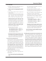
1
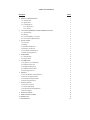
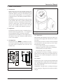
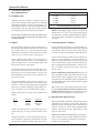
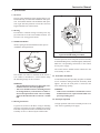
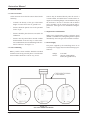
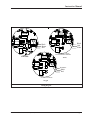
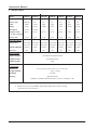
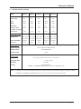
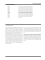
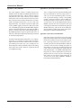
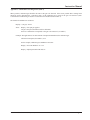
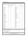
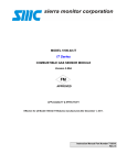
MODEL 4105 SERIES
GAS SENSOR MODULE
WITH DIGITAL DISPLAY AND
NON-INTRUSIVE CALIBRATION
4-20 mA
MODEL 4105 SERIES
GAS SENSOR MODULE
WITH DIGITAL DISPLAY AND
NON-INTRUSIVE CALIBRATION
4-20 mA
APPLICABILITY & EFFECTIVITY
This manual provides instructions for the following Sierra Monitor products:
Model
4105-02
4105-03
4105-04
4105-05
4105-06
4105-07
4105-10
4105-12
4105-21
4105-22
4105-25
4105-26
Description
Combustible Gas Sensor Module with Non-Intrusive Calibration
Oxygen Gas Sensor Module with Non-Intrusive Calibration
Carbon Monioxide Gas Sensor Module with Non-Intrusive Calibration
Hydrogen Sulfide Gas Sensor Module with Non-Intrusive Calibration
Chlorine Gas Sensor Module with Non-Intrusive Calibration
Hydrogen Gas Sensor Module with Non-Intrusive Calibration
Sulfur Dioxide GasSensor Module with Non-Intrusive Calibration
Nitrogen Dioxide Gas Sensor Module with Non-Intrusive Calibration
Hydrogen Chloride Gas Sensor Module with Non-Intrusive Calibration
Hydrogen Cyanide Gas Sensor Module with Non-Intrusive Calibration
Ammonia Gas Sensor Module with Non-Intrusive Calibration
Hydrogen Flouride Gas Sensor Module with Non-Intrusive Calibration
The instructions are effective for the above models as of April 1, 1998
Instruction Manual Part Number T13008
Rev. E1
TABLE OF CONTENTS
SECTION
1. PRODUCT DESCRIPTION
1.1 Introduction
1.2 Application
1.3 Configuration
1.3.1 Electronics
1.3.2 Sensor
2. CAUTIONS WARNINGS & RECOMMENDATIONS
2.1 Introduction
2.2 Wiring
2.3 Sensor Modules - General
2.4 Preventative Maintenance
3. QUICK START
3.1 Overview
3.2 Wiring
3.3 Module Installation
3.4 Wiring Connection
3.5 Transmitter Installation
3.6 Start-up & Operation
4. OPERATION
4.1 Introduction
4.2 Signal Value
5. CALIBRATION
5.1 Frequency of Calibration
5.2 Calibration Process
5.3 Equipment Required
5.4 Calibration Procedure
5.5 Fault Supervision
6. SERVICE
6.1 Sensor Module Configuration
6.2 Enclosure Replacement
6.3 Transmitter Replacement
6.4 Sensor Replacement
7. INSTALLATION
7.1 Sensor Locations
7.2 Sensor Mounting
7.3 Explosion Proof Installation
7.4 Power Supply
8. SPECIFICATIONS
9. REPLACEMENT PARTS
10. WARRANTY
11. APPENDICES
PAGE
1
1
1
1
1
1
2
2
2
2
2
3
3
3
3
3
3
3
4
4
4
5
5
5
5
5
5
6
6
6
6
6
8
8
8
8
8
10
13
13
14
Instruction Manual
1.
PRODUCT DESCRIPTION
1.1 Introduction
Model 4105 Series Gas Sensor module features nonintrusive calibration, 4-20 mA output signal and local
continuous display of the gas concentration in ppm
(toxics), % LEL (Combustibles), or % vol (Oxygen). It
is designed for use with industry standard control instruments.
This manual provides instructions for 4105 series gas
sensor modules that utilize common packaging and
transmitter electronics with different sensors for detection of various gases. The full model number of
the gas sensor module includes a suffix, 4105-XX,
where “XX” is a number that identifies a gas type.
1.2 Application
The Model 4105-XX Gas sensor is intended for use in
ambient monitoring applications. It is designed for
fixed installation and for continuous operation.
Optional fittings and adapters can be supplied by Sierra Monitor to provide continuous sample delivery
to the sensor module.
1.3 Configuration
The gas monitor is comprised of a NEMA-7/4 enclosure which contains the transmitter electronics and a
gas sensor which is installed in one of the two 3/4"
conduit hubs.
5.42"
4.50"
1.75"
2.81"
MODEL 4105-02
Combus tibles % LEL
Unity
SPAN
1.3.1 Electronics
When installed, the transmitter electronics will be connected to a power supply and control device via three
wire cable.
The electronics provide a 4-20 mA current loop which
is proportional to the full sensitivity of the sensor.
Integral features include:
- L.C.D. readout of ppm of gas concentration.
- Magnetic switches for non-intrusive calibration.
- Visual indicators for fault condition.
- Electrical fault (0 mA) to controller.
The transmitter electronics assembly includes a
printed circuit assembly and a cover plate which contains the L.C.D. readout and magnetic switches for
calibration.
FAULT /KEYPAD
5.50"
Figure 1.1 Model 4105 Gas Sensor Module
ZERO
Ph. 408-262-6611
Milpitas, CA
CAL
7.25"
1.3.2 Sensor
The gas sensor cell is enclosed in a threaded housing
and is plugged into a signal card located in the enclosure. This configuration allows for easy field replacement of the sensor cell.
Combustible: The gas sensor is a catalytic bead type.
Figure 1.2 Outline View - Gas Sensor Module
Model 4105 Gas Sensor Module (12/02)
Toxics & Oxygen: The gas sensor is an Electro Chemical type.
Page: 1
Instruction Manual
2.
CAUTIONS WARNINGS &
RECOMMENDATIONS
2.1 INTRODUCTION
Although the sensor module is designed and constructed for installation and operation in industrial
applications including “hostile” environments, caution should be taken to insure that the installation is
in compliance with this instruction manual and that
certain procedures and conditions are avoided.
READ AND UNDERSTAND THIS INSTRUCTION
MANUAL BEFORE OPERATING OR SERVICING
THIS EQUIPMENT.
2.2 WIRING
Wire Gauge
20 AWG
18 AWG
16 AWG
14 AWG
12 AWG
Maximum Length
2,000 Ft.
3,000 Ft.
4,000 Ft.
6,500 Ft.
9,000 Ft.
Table 2.1
Recommended Wire/Cable Gauge
NOTE: Temperature rating of cable wire insulation
must be above 75oC (85oC or greater rated wiring is
recommended). If cable runs through higher temperature environments, it should be specified for that environment.
2.3 SENSOR MODULES - GENERAL
Electro magnetic and radio frequency interference to
the analog communication between the sensor and
the controller may occur. The manufacturer recommends that extra caution be taken where the installation is near any sources of these interferences:
Avoid running sensor cable close to high power
cables, radio transmission lines, or cables subject to
pulses of high current. Avoid running cables near
large electric motors or generators.
Use shielded cable in any location which may be expected to be electrically noisy or where cable is expected to be in close contact with AC wiring. The
shield should be connected to the controller common, one side only.
The wiring should be run in either a cable tray or
conduit as required by applicable code and area classification. Control wiring should not be installed in a
cable tray or conduit with higher voltage and AC circuits. See Table 2.1 for recommended wire gauge.
Wiring connections at the gas sensor module are as
follows:
Sensors should be facing down. Avoid installing sensor modules where they will be unnecessarily exposed
to wind, dust, water (esp. direct hose down), shock,
or vibration. Observe temperature range limitations.
Sensors may be adversely affected by prolonged exposure to certain materials. Loss of sensitivity, or
corrosion, may be gradual if such materials are present
in low concentrations. These materials include: Halides (compounds containing chlorine, fluorine, bromine, or iodine), silicones, acid vapors, caustic liquids or vapors.
Sensor modules must not be painted. Paint may contain compounds which will contaminate the sensor.
Paint will also cause clogging of the sintered metal
cup and will cause difficulties during attachment of
the calibration fitiing. The module should be tagged
“DO NOT PAINT”.
When sensors are replaced the thread on the sensor
housing must be lubricated with an antizieze compound non-silicone based to avoid metal to metal
binding which will damage the housing threads.
2.4 PREVENTATIVE MAINTENANCE
Wire#
1
2
3
Function
Power
Signal
Ground
Terminal
PWR
SIG OUT
GND
Connect an earth ground to the ground screw provided in the base of the gas sensor module enclosure.
All splices must be via either a lug and terminal system or soldered. Improperly spliced cable can result
in corrosion, resistance changes and system errors.
Page: 2
DUST AND DIRT CONTROL: When calibration is
performed the controller and sensors should be
checked visually to determine if dust or dirt build up
needs to be removed. This cleaning should be done
with dry instruments such as compressed air, cloth
wipes or wisk broom.
WIRING OR CABLE CONDITIONS: Any wiring or
cables which are not in conduit should be checked
once a year for damage to insulation or corrosion
of splice or terminal points.
Model 4105 Gas Sensor Module (12/02)
Instruction Manual
3.
QUICK START
3.1 Overview
The gas sensor module has been supplied factory calibrated and ready for immediate installation and operation. An installer familiar with installation and operation of gas detection products can use this section to
begin immediate use of the monitor.
PPM
3.2 Wiring
Provide three conductor wiring from the power supply/control device to the sensor module location. See
section 2.2 for wiring specifications.
MODEL 4105-05
H2 S PPM
GAS MONITOR
FAULT
Unity
SPAN
ZERO
3.3 Module Installation
Remove spring on electromechanical sensor prior to
installation. See Figure below.
Figure 3.1
Typical Vertical Mounting on Conduit
Terminal positions on the I/O printed circuit assembly
are labeled PWR (power), OUTSIG (signal), GND (TB2).
Make the corresponding connections to the control
device/power supply.
The sensor harness should remain connected to the
I/O assembly at “TB1”.
The module can either be installed on the end of a
3/4" conduit, or attached to a vertical surface using
the mounting flange on the enclosure.
WARNING:
- The installation must meet any hazardous environment codes for electrical equipment.
- The sensor module enclosure mounting must be
far enough from any vertical surface to allow removal and replacement of the sensor assembly
which is threaded into the second 3/4" conduit
hub.
3.5 Transmitter Installation
To install the front panel assembly, align the two thumb
screws with their mating stand-offs and firmly hand
tighten. Be sure the front panel is centered in the
4105-XX housing opening.
WARNING:
- If the sensor transmitter is installed in a classified hazardous area, replace the threaded cover
prior to providing power.
3.6 Start-up & Operation
3.4 Wiring Connection
To gain access to the I/O PCB for wiring or mounting
purposes, loosen the two captive thumb screws in the
4105-XX front panel and remove the PANEL/CPU PCB
assembly as far as is allowed by the ribbon cable.
Model 4105 Gas Sensor Module (12/02)
To begin operation of the sensor module provide 21-30
VDC from a regulated power supply.
Page: 3
Instruction Manual
4.
OPERATION
4.1 Introduction
Under normal conditions the sensor module does not
require operator or technician intervention. The following are conditions under which the module requires
attention:
- Routine periodic calibration.
- Calibration after a high gas alarm.
- Sensor replacement on a planned schedule or
when a sensor failure occurs.
- Periodic cleaning as necessary.
- Unanticipated maintenance.
4.2 Signal Value
During normal operation the current loop of the sensor module and the controller will be between 4 mA
indicating no presence of gas, and 20 mA indicating
that the full scale concentration of gas is present. The
signal value is proportional to the concentration of
gas present.
FAULT /KEYPAD
FAULT /KEYPAD
MODEL 4105-02
Combustibles % LEL
Unity
SPAN
ZERO
MODEL 4105-05
H2S
PPM
Unity
SPAN
Ph. 408-262-6611
ZERO
Ph. 408-262-6611
Milpitas, CA
Milpitas, CA
CAL
CAL
Figure 4.1
Transmitter Cover Plate
Page: 4
Model 4105 Gas Sensor Module (12/02)
Instruction Manual
5.
CALIBRATION
5.1 Frequency of Calibration
The manufacturer recommends that the gas sensor
module be calibrated every ninety days.
5.2 Calibration Process
The output signal of the gas sensor module is calibrated using a span mixture containing a known concentration of the gas of interest. The concentration
of the span gas must be within the full scale of the
sensor module and should be either 50% of the full
scale, or approximately equal to the lowest alarm level.
Calibration requires application of the span gas to the
sensor and adjustment of the “SPAN” magnetic switch
making the module signal output and display equivalent to the concentration of sample gas. The 4-20 mA
output is held at 1.5 mA while activated for calibration
to prevent alarms being tripped by calibration gas
application.
5.3 Equipment Required
The following tools and equipment will be required
for calibration:
- Magnetic tool
- Gas Sensor Calibrator, Model 1260-XX
or Model 1200-26 or permeation tube
- Calibration Gas
- Disbursing Calibration Adapter (Model 535801)
5.4 Calibration Procedure
Routine calibrations are easily performed using the
magnetic tool provided with each sensor.
Briefly hold the magnet tool close to the small dot
located on the lower edge of the front panel. The
arrow on the upper left side of the LED will illuminate
and the 4-20 mA output is locked at 1.5 mA, indicating
that the sensor module is ready for calibration. Simply expose the sensor to a ZERO gas and observe the
L.C.D. readout. In normal situations, simply exposing
the sensor to an atmosphere free of the gas of interest
is satisfactory. If it does not return to the correct
ZERO reading, a ZERO adjustment is required. Hold
the magnet close to the UP ZERO or DOWN ZERO
indicators and adjust the reading to the correct ZERO
reading.
Connect the calibration adapter and expose the sensor to an appropriate SPAN gas using a span mixture
containing a known concentration of the gas of interest at a minimum flow rate of 300 cc/minute. (Use permeation tube for 4105-25) Allow 3-5 minutes before
making any adjustments.
If the L.C.D. does not display the correct SPAN value,
a SPAN adjustment is required. With the arrow still
flashing, hold the magnet close to the UP SPAN or
DOWN-SPAN indicators and adjust the reading to the
correct SPAN value. (The 4-20 mA out is automatically adjusted.)
The monitor is now calibrated. Deactivate calibration
by holding the magnet close to the small dot again.
This releases the 1.5 mA lock.
5.5 Fault Identification
A Fault condition is detected if the sensor output drifts
far enough negative to cause the 4-20 mA output to
reach 1.5 mA (±15% of full scale) or the sensor failure.
The sensor module demonstrates that a fault condition exists by illuminating the RED LED on the front
panel and by holding the 4-20 mA output at 0 mA.
These conditions will exist until the fault is corrected.
Model
4105-02
4105-03
4105-04
4105-05
4105-06
4105-07
4105-10
4105-12
4105-21
4105-22
4105-25**
4105-26
Gas
CH4
O2
CO
H2S
Cl2
H2
SO2
NO2
HCl
HCN*
NH3
HF
Min. Flow Rate
(cc/min)
100
100
150
300
300
300
300
300
300
300
400
500
*Note: SO2 may be used instead of HCN to
calibrate: 10ppm SO2 = 16 ppm HCN
*Note: H2S may be used instead of HCl to
calibrate: 10 ppm H2S = 20 ppm HCl
** Note: Use permeation tube for 4105-25
Table 4.1
Calibration Span Gas Flow Rates
Model 4105 Gas Sensor Module (12/02)
Page: 5
Instruction Manual
6.
6.3 Transmitter Replacement
SERVICE
6.1 Sensor Module Configuration
The gas sensor module is comprised of the following
sub assemblies:
4105-XX
Gas Sensor Module
-SPM25002 Transmitter Assembly
-SPT25013 Combustible Gas Sensor
Module Transmitter Assembly
-SPM25003 Oxygen and Toxic Gas Sensor
Module Transmitter Assemby
(must specify gas type)
-4205-XX
Sensor Assembly
[Where "xx" is the suffix to the gas sensor
module number (Table 6.1)]
There is no field servicable components below
the sub assembly level.
Warning: Prior to removal of the transmitter assembly, remove system power at
the controller or other power source.
Model
Gas Module
4105-02
4105-03
4105-04
4105-05
4105-06
4105-07
4105-10
4105-12
4105-21
4105-22
4105-25
4105-26
Combustible
Oxygen
CO
H2S
Cl2
H2
SO2
NO2
HCl
HCN
NH3
HF
Table 6.1
Model Numbers
The transmitter assembly should be replaced when it
is determined that it is unreliable, noisy or cannot be
adjusted for calibration. This may occur due to age,
corrosion or failed components.
To replace the transmitter assembly:
1. Remove the cover of the main enclosure.
2. Remove the front panel by loosening the two captive thumb screws in the 4105-XX front panel and
remove the PANEL/CPU PCB assembly as far as is
allowed the by the ribbon cable.
3. Unscrew the sensor harness from the transmitter
(TB1).
4. Remove the three wires from the P,S,G terminals
(TB2).
5. Remove the I/O PCB.
6. Reverse the preceding steps to install the new
transmitter.
7. Restore power and allow a minimum of 30 minutes
for stabilization before re-calibration.
6.4 Sensor Replacement
The sensor should be replaced when it is determined
that:
-
It is no longer possible to obtain correct Zero and
Span values at the test points or at the controller.
The sensor output signal is noisy, causing erroneous gas level readings.
To replace the sensor:
1. Remove the gas sensor module enclosure lid.
2. Remove the front panel by loosening the two captive thumb screws in the 4105-XX front panel and
remove the PANEL/CPU PCB assembly as far as is
allowed the by the ribbon cable.
3. Unscrew the sensor wires from the transmitter..
6.2 Enclosure Replacement
The enclosure should be replaced if the lid threads or
conduit threads have been damaged, or if the enclosure has corroded sufficiently that it no longer meets
the required NEMA classification.
4. Unscrew the old sensor assembly from the enclosure conduit hub. Remove the sensor assembly
with its harness.
5. Reverse the preceding steps to install the sensor
assembly.
To replace the enclosure follow the transmitter and
sensor assembly removal instructions, remove the
damaged enclosure from it’s conduit or wall mounting, install a new enclosure and continue the transmitter and sensor assembly replacement instructions.
Page: 6
Model 4105 Gas Sensor Module (12/02)
Instruction Manual
6.4a. Combustibles
1. Verify the voltage across A to R equals 2 volt. If
not, adjust volts potentiometer R11
•
The 4105-XX has 4 fixed ranges of sensitivity,
which are selectable via JP1.
2. Verify the voltage from GND (TB2) to VOUT
equals 0.4 volts. If not adjust BAL potentiometer (R2)
•
The JP1 positions are labeled 1, 2, 3 & 4.
•
JP1 jumper set the coarse up scale SPAN values
by affecting the gain of the analog circuit.
•
JP1 is set correctly if a 50% of full-scale gas
read between 1.0 & 1.4 volts on VOUT.
•
Fine-tuning of these settings is done later by
adjusting the 4105-XX via magnetic control.
•
Select the jumper at JP1 as required. JP1 gain
values are as follows:
JP1 with jumper in position 1 = GAIN = 5.5
JP1 with jumper in position 2 = GAIN = 4
JP1 with jumper in position 3 = GAIN = 2.3
JP1 with jumper in position 4 = GAIN = 1.5
JP1 with no jumper = GAIN = 1
•
More than one jumper may be installed to allow
additional gain value. Multiple jumper are additive in relation of the gain value. For example, if
a gain of 6.5 is needed, jumper should be placed
in positions 2 and 3 to provide a gain of 6.3.
3. Verify that the voltage at VOUT is equal to the
voltage desired.
•
•
The VOUT test point on the I/O PCB has a range
of 0.4-2 volts for 0-100% of the measurement
range. Therefore, 0%=0.4 volts, 25%=0.8,
50%=1.2 volts, 75%=1.6 volts, 100%=2 volts.
Selecting the jumper at JP1 assigns one of four
different sensitivity ranges to the module. The
JP1 positions are labeled 1, 2, 3 & 4. JP1 jumper
set the coarse up scale SPAN values by affecting the gain of the analog circuit. JP1 is set
correctly if an application of 50% of full scale
reads between 1.0 & 1.4 volts on VOUT. Finetuning of these setting is done later by adjusting the 4105-02 magnetic control.
JP1 gain values are as follows:
JP1 with jumper in position 1 = GAIN = 51
JP1 with jumper in position 2 = GAIN = 26
JP1 with jumper in position 3 = GAIN = 12.5
JP1 with jumper in position 4 = GAIN = 7
JP1 with no jumper = GAIN = 1
•
More than one jumper may be installed to allow
additional gain value. Multiple jumper are additive in relation of the gain value. For example, if
a gain of 20 is needed, jumper should be placed
in positions 3 and 4 to provide a gain of 20.
6.4b LEL Sensor Fault Supervision
The typical failure mode of catalytic bead sensors
is the reference or active beads open circuit. In
rare cases a short circuit may develop. The 410502 is equipped with fault detection circuitry that
detects either condition. A FAULT is also signaled
if the output drifts below -10% of full scale. The
4105-02 signals a FAULT condition exists by overwriting the LCD with a FLt message, flashing the
red LED on the front panel and clamping the 420mA output at 0mA. These conditions remain until
the FAULT is corrected.
Note: Allow the new sensor to stabilize for a minimum of 30 minutes and then calibrate using the
procedure in Section 5.
6.4d Missing Electromechanical Sensor Fault Supervision
Many electromechanical sensor housings allow for
easy replacement of defective sensors by making the
sensors 'plug in'. A problem is that if the sensor is
removed, many transmitters continure to display the
safe reading of 0 PPM. The 4105-XX is equipped with
fault detection circuitry that detects a missing sensor.
Within several minutes of removing an EC sensor, the
4105-XX will signal a FAULT condition. A FAULT is
also detected if the sensor output drifts below -10%
of full scale. the Model 4105-XX demonstrates a
FAULT condition exists by overwriting the LCD reading with FLt, illuminating the red LED on the front
panel and by clamping the 4-20mA output at 0mA.
These conditions exist until the FAULT is corrected.
6.4c Electrochemical (Oxygen and Toxics)
Verify that the voltage VOUT is equal to the voltage as desired.
•
The VOUT test point on the I/O PCB has a range
of 0.4-2 volts for 0-100% of the measurement
range.
Model 4105 Gas Sensor Module (12/02)
Page: 7
Instruction Manual
7.
INSTALLATION
7.1 Sensor Locations
Select locations for each of the sensors based on the
following:
-
Consider the density of the gas to determine
height of sensor above floor or ground level.
-
Sensors should be placed close to the potential
source of gas.
-
Sensors should be placed in areas accessible for
calibration.
Sensors may be mounted directly onto the end of a
vertical conduit, or bracketed to a vertical surface using the two mounting flanges. Insure that the body of
the enclosure is at least 1" from the wall so that the
sensor assembly can be rotated for removal and replacement. See Figure 6.1 for installation configurations.
7.3 Explosion Proof Installation
-
Sensors must be pointed down and the conduit
should include an inverse trap to reduce moisture (condensation) from accumulating in the electronics enclosure. See Figure 7.1.
Where area classification requires explosion proof
(NEMA-7) installation a sealing fitting will be required
immediately above the gas sensor module enclosure.
7.4 Power Supply
The power supplied by the controlling device or an
external power supply must meet the following specifications:
7.2 Sensor Mounting
Where possible sensor modules should be installed
with the sensor facing vertically down. The lid of the
sensor module should face out for easy access.
Voltage:
Current:
21-30 VDC
180 mA (Combustibles)
40 mA (Oxygen & Toxics)
Figure 7.1
Gas Sensor Module Installation
Page: 8
Model 4105 Gas Sensor Module (12/02)
Instruction Manual
V OUT
VOU T
P1
R I BB ON C AB LE
T O C PU ASS Y.
P1
R IB BON C ABL E
T O CP U AS SY.
U2
U2
R
T B2
U1
Pwr./Sig.
J P1
BA L
C
A
T B1
TB 2
R1 1
U1
Pw r./Sig.
Black
Brown
Red
U3
U5
R
C
TB 1
Sensor
1 2 3 4
V O LT S
R2
U7
S
Sensor
1 2 3 4
R 19
A
B
JP 2
JP 1
U5
Black
Red
White
U4
U4
VOU T
P1
R IB BON C ABL E
T O CP U AS SY.
Combustible
ST-46A/EC I/O PCB FOR
ELECTROCHEMICAL SENSORS
R 19
U2
Toxics
U7
S
TB 2
R
Pw r./Sig.
C
TB 1
U1
Sensor
1 2 3 4
A
B
JP 2
JP 1
U5
Short R&C
Black
Red
U4
ST-46A/EC I/O PCB FOR
Oxygen
Figure 7.2
Wiring Diagram
Model 4105 Gas Sensor Module (12/02)
Page: 9
Instruction Manual
8.
SPECIFICATIONS
Model
4105-02
4105-03
4105-04
4105-05
4105-06
4105-07
4105-10
Comb.
O2
CO
H2S
Cl2
H2
SO2
Catalytic
E.C.
E.C.
E.C
E.C.
E.C.
E.C.
Units
%LEL
% Vol
ppm
ppm
ppm
ppm
ppm
Range
0-100
0-25%
0-1000
0-100
0-10
0-1000
0-100
Resolution
3% F.S.
0.1% F.S.
1
0.1
0.1
2
0.5
Response Time
to 90% of signal
Note 1
10 sec.
25 sec.
30 sec.
60 sec.
30 sec.
20 sec.
3 Yrs
2 yrs
2 yrs
2 yrs
2 yrs
2 yrs
2 yrs
Gas
Sensor Type
Sensor Life 2
Operating Range
Temperature
Relative Humidity
Pressure
14 to 158oF 19 to 122oF 14 to 122oF 14 to 122oF 14 to 122oF 14 to 122oF 14 to 122oF
-10 to 75oC -7 to 50oC -10 to 50oC -10 to 50oC -10 to 50oC -10 to 50oC -10 to 50oC
10-95%
5-99%
15-90%
15-90%
15-90%
10-90%
15-90%
10%
10%
10%
10%
10%
10%
10%
Electrical Data
Input Voltage DC
19-30VDC at less than 100 mA
Output-Normal
4-20 mA DC linear
Output-Trouble
0 mA
Construction
Dimensions
Weight (Module)
H: 7.6", D: 4.6", W: 4.2" (19.3 x 11.7 x 10.7 cm)
5.0 lb. (2.2 kg)
Mounting
3/4" NPT
Housing
Explosion proof
(NEMA 7) / NEMA 4X Enclosure (Div. I, Class 1, Groups B, C, D)
Notes: 1. Step to 50% LEL within 10 sec, recovery to 10% LEL within 30 sec.
2. Sensor life is for use at standard temperature and pressure with occasional
exposure to the gas of interest
Page: 10
Model 4105 Gas Sensor Module (12/02)
Instruction Manual
8.
SPECIFICATIONS (Continued)
4105-12
4105-21
4105-22
4105-25 3
4105-26 3
NO2
HCL
HCN
NH
HF
Sensor Type
E.C.
E.C.
E.C.
E.C.
E.C.
Units
ppm
ppm
ppm
ppm
ppm
Range
0-20
0-20
0-20
0-50
0-10
Resolution
0.2
0.5
0.1
0.1
0.5
35 sec.
150 sec
70 sec.
45 sec.
30 sec.
2 yrs
2 yrs
2 yrs
N/A
N/A
Model
Gas
Response Time
to 90% of signal
Sensor Life 2
3
Operating Range
Temperature
Relative Humidity
Pressure
14 to 122oF 14 to 122oF 14 to 122oF 14 to 113oF 14 to 113oF
-10 to 50oC -10 to 50oC -10 to 50oC -10 to 45oC -10 to 45oC
15-90%
10%
15-90%
10%
15-90%
20-90%
20-90%
10%
10%
10%
Electrical Data
Input Voltage DC
19-30 VDC at less than 100 mA
Output-Normal
4-20 mA DC linear
Output-Trouble
0 mA
Construction
Dimensions
H: 7.6", D: 4.6", W: 4.2" (19.3 x 11.7 x 10.7 cm)
Weight (Module)
5.0 lb. (2.2 kg)
Mounting
3/4" NPT
Housing
Explosion proof
(NEMA 7) / NEMA 4X Enclosure (Div. I, Class 1, Groups B, C, D)
Notes: 2. Sensor life is for use at standard temperature and pressure with occasional exposure to the gas of interest
3. Diffusion via membrane. Dimensions are H: 10.2", D: 6.0", W: 6.0" (25.9 x 15.2x 15.2 cm)
Model 4105 Gas Sensor Module (12/02)
Page: 11
Instruction Manual
8.
SPECIFICATIONS (Cont.)
Cross Sensitivities (toxic sensors)
Model
Number
Gas
Type
Reading from 100 ppm of interfering gas
Cl2
H2
SO 2
NO2
CO
H2S
NO
HCl
4105-04
CO
100
315
-15
<40
50
-55
30
4105-05
H 2S
<0.5
100
-20
<0.1
<15
-15
4105-06
Cl 2
0
<-10
100
0
0
HCN
C2H4
2
40
<50
0
0
0
0
105
0
0
0
0
4105-07
H2
<1
<20
0
100
3
0
35
3
35
85
4105-10
SO 2
<1
0
-40
0
100
-100
0
0
15
0
4105-12
NO 2
0
-20
90
0
0
100
0
0
-3
0
4105-21
HCl
0
75
-10
0
35
-2
0
100
-8
0
4105-22
HCN
-50
0
160
-190
-5
30
100
<1
4105-25
NH
<0.5
0
0
0
-
40
0
0
-
-
-
0
0
9
0
9
5
-
6
-
-
3
4105-26
Page: 12
HF
Model 4105 Gas Sensor Module (12/02)
Instruction Manual
9.
REPLACEMENT PARTS
4205-02
4205-03
4207-04
4205-05
4205-06
4207-07
4207-10
4207-12
4207-21
4207-22
4207-25
4207-26
5311-00
Sensor Assembly, Combustible, Non-Intrusive
Sensor Assembly, 4-20 mA O2, Non-Intrusive
Sensor Assembly, 4-20 mA CO, Non-Intrusive
Sensor Assembly, 4-20 mA H2S, Non-Intrusive
Sensor Assembly, 4-20 mA Cl2, Non-Intrusive
Sensor Assembly, 4-20 mA H2, Non-Intrusive
Sensor Assembly, 4-20 mA SO2, Non-Intrusive
Sensor Assembly, 4-20 mA NO2, Non-Intrusive
Sensor Assembly, 4-20 mA HCl, Non-Intrusive
Sensor Assembly, 4-20 mA HCN, Non-Intrusive
Sensor Assembly, 4-20 mA NH3, Non-Intrusive
Sensor Assembly, 4-20 mA HF, Non-Intrusive
Rainshield
10. LIMITED WARRANTY
SIERRA MONITOR CORPORATION warrants its products
to be free from defects in workmanship or material under
normal use and service for two years after date of shipment.
SMC will repair or replace without charge any equipment
found to be defective during the warranty period. Final
determination of the nature and responsibility for defective
or damaged equipment will be made by SMC personnel.
All warranties hereunder are contingent upon proper use in
the application for which the product was intended and do
not cover products which have been modified or repaired
without SMC approval or which have been subjected to
accident, improper maintenance, installation or application,
or on which original identification marks have been removed
or altered. This Limited Warranty also will not apply to
interconnecting cables or wires, consumables (ie. calibration gases, batteries, sensors), nor to any damage resulting
from battery leakage.
Model 4105 Gas Sensor Module (12/02)
In all cases SMC’s responsibility and liability under this
warranty shall be limited to the cost of the equipment. The
purchaser must obtain shipping instructions for the prepaid
return of any item under this warranty provision and compliance with such instruction shall be a condition of this warranty.
Except for the express warranty stated above, SMC disclaims
all warranties with regard to the products sold hereunder
including all implied warranties of merchantability and fitness and the express warranties stated herein are in lieu of
all obligations or liabilities on the part of SMC for damages
including, but not limited to, consequential damages arising
out of/or in connection with the use or performance of the
product.
Page: 13
Instruction Manual
Appendix A: Unity Gain Mode
The Unity magnetic control is available during CAL
MODE to allow the ZERO and SPAN adjustments to be
centered within their range. This is similar to setting a
potentiometer so the wiper terminal is exactly halfway
between the clockwise and counterclockwise terminals.
this is identified as the UNITY GAIN mode. In UNITY
GAIN the ZERO controls have a ± 15% of full scale
adjustment range. For example, in UNITY GAIN, if the
sensor's ZERO output has drifted so high that it reads
15% with ZERO gas applied, the DOWN ZERO magnetic
control could still bring the 4105-XX reading to ZERO.
However, it will be at the end of its adjustment range. If
the ZERO adjustment required is greater than ±10% of
full scale, a BALANCE adjustment should be performed
as described in Appendix A.
In UNITY GAIN the SPAN controls have a .5 to 2 adjustment range. For example, in UNITY GAIN, if a sensor's
output sensitivity has been reduced to the point where
50% SPAN gas provides only a 25% reading, the UP
SPAN magnetic control could still calibrate the reading
to the proper value of 50%. However, it will be at the end
of its adjustment range.
Page: 14
Appendix B: L.C.D. Readout Calibration Procedure
The 3 1/2 digit LCD meter span and decimal points
may be configured for full scale ranges such as 1100, 0-25, 0-10.0, 0-1000 and many others. Zero percent of full-scale readings, or those corresponding
to 4mA, are always assumed to equal a reading of 0.
Holding the magnet over the CAL key for at least 5
seconds enters the LCD METER SPAN SETUP
MODE. After this, the current setting for 100% full
scale is displayed and may be modified using the UP/
DOWN SPAN keys. This sets the LCD reading displayed when the 4-20mA output equals 30mA. Decimal points are added with the UNITY key.
Appendix C: End of Sensor Life Indication
Old sensors near the end of their service life require
higher gain settings. M4105-XX "END OF SENSOR
LIFE" (ESL) feature may be used to indicate condition. A span trip point may be entered that when exceeded, causes the LCD to flash and ESL reading for
2-seconds each 10 seconds. Holding the magnet to
the UNITY key for at least 5 seconds brings the LCD
a span value set-point reading for setting when the
ESL indication trips. CAL MODE GAIN adjustments
range between .5 and 2 and the ESL set-point is adjustable between 1.5 and 2.01 with 2.01 turning the
ESL feature off. The current span setting may be
viewed on the LCD during NORMAL MODE by
touching the DOWN SPAN key.
Model 4105 Gas Sensor Module (12/02)
Instruction Manual
Appendix C: Combustible Gas Scaling Factors (Table 1)
Where possible, calibration gas should be the same as the gas to be detected. If this is not possible then a scaling factor
should be used to determine the “equivalent value” of the calibration gas in terms of the gas to be detected. (Note:
Concentration of calibration gas must be less than the factor number listed on Table 1).
The formula for calibration is as follows:
Display = (Cal gas) / Factor
where: Display = the span gas applied
Cal gas is the percent methane used for calibration.
Factor is a number that corresponds to the gas to be measured. (see Table 1)
Example: The application is for measurement of Propane and Methane is the calibration gas.
The factor for Propane (from Table 1) is 55.
For the example, calibration gas is Methane at 40% LEL.
Display = 40% LEL Methane / 55 = 0.73
Display = Adjust span until LCD reads 73.
Model 4105 Gas Sensor Module (12/02)
Page: 15
Instruction Manual
COMBUSTIBLE GAS SCALING FACTORS
For combustible gas monitoring, a calibration standard of Methane or Propane my be used in conjunction with scaling
factors to cause alarm function in %LEL scale of another gas as follows:
GAS
Acetaldehyde
Acetic Acid
Acetic Anhydride
Acetone
Acetylene
Alkyl Alcohol
Ammonia
n-Amyl Alcohol
Aniline
Benzene
Biphenyl
1,3-Butadiene
n-Butane
iso-Butane
Butene-1
cis-Butene-2
trans-Butene-2
n-Butyl Alcohol
iso-Butyl Alcohol
tert-Butyl-Alcohol
n-Butyl Benzene
iso-Butyl Benzene
n-Butyric Acid
Carbon Disulfide
Carbon Monoxide
Carbon Oxysulphide
Chlorobenzene
Cyanogen
Cyclohexane
Cyclopropane
n-Decane
Diethylamine
Dimethylamine
2,3-Dimethylpentane
2,3-Dimethylpropane
Dimethylsulphide
1,4-Dioxane
Epichlorohydrin
Ethane
Ethyl Acetate
Ethyl Alcohol
Ethylamine
Ethyl Benzene
Ethyl Bromide
Ethyl Chloride
Ethylcyclopentane
Ethylene
Ethylenedichloride
Ethyleneoxide
METHANE
FACTOR
60
54
46
52
57
51
126
33
39
41
25
56
58
52
45
48
51
34
53
74
31
32
38
18
75
93
34
89
41
62
33
49
58
40
40
43
45
45
68
51
73
53
36
91
57
40
71
66
52
PROPANE
FACTOR
109
98
83
94
103
92
229
59
71
74
45
101
106
94
82
88
92
62
96
134
57
58
69
32
137
169
62
162
74
113
59
88
105
72
72
79
81
82
123
93
132
95
65
165
103
72
128
120
94
GAS
Diethyl Ether
Dimethoxyethane
Dimethyl Ether
Dimethylformamide
Ethyl Formate
Ethylmercaptan
n-Heptane
n-Hexane
Hydrazine
Hydrogencyanide
Hydrogen
Hydrogen Sulfide
Methane
Methyl Actetate
Methyl Alcohol
Methylamine
Methyl Bromide
Methyl Chloride
Methylcyclohexane
Methylenedichloride
Methylethylether
Methylethylketone
Methyl Formate
Methylmercaptan
Methylpropionate
Methyl n-propylketone
Napthalene
Nitromethane
n-Nonane
n-Octane
n-Pentane
i-Pentane
Propane
n-Propyl Alcohol
n-Propylamine
n-Propylchloride
Propylene
Propyleneoxide
iso-Propylether
Propyne
Toluene
Triethylamine
Trimethylamine
Vinylethylether
o-Xylene
m-Xylene
p-Xylene
JP-4 (Jet Fuel)
METHANE
FACTOR
46
42
63
46
44
56
39
37
45
48
77
41
100
50
86
77
90
102
44
93
44
41
67
61
51
40
34
34
31
37
46
46
55
47
48
50
52
46
44
42
40
40
48
42
36
39
39
41
PROPANE
FACTOR
84
75
113
83
80
102
70
67
82
86
139
74
181
90
156
140
162
186
80
168
80
75
121
110
93
73
62
62
57
68
83
84
100
85
88
90
93
83
79
75
73
72
88
76
65
71
71
73
NOTES:
1.
2.
3.
Scaling factors are not FMRC approved.
Base data source: EEV sensor specification catalog. (EEV claims some data is the result of specific
other data is empirically derived.)
Display = Cal Gas / Factor = % LEL
=> must be less than 1
tests,
TABLE 1
COMBUSTIBLE GAS SCALING FACTORS
Page: 16
Model 4105 Gas Sensor Module (12/02)