1
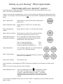
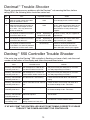
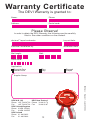
GB
Installation And User Instructions
Devimat™ Warm Floor System
Installation Instructions
User Guide
Trouble Shooter
1
Existing Floor
Wooden Floors
Concrete Floors
Maximum load per m2
100 W/m2
150 W/m2
In all above situations, the floor temperature must be controlled with a DEVI floor sensor and
Devireg™ 550 thermostat/timer, or Devireg™ 130 thermostat.
INSTALLATION: KEY POINTS
•
Before laying the mat the floor sensor (in controller box) MUST be installed. The
sensor is fitted into a tube (in mat box) which should be laid 20-30cm across
the floor under the mat between a cable loop.
•
Before laying check the continuity of the cable, it should match the Ohm rating
on the Devimat™ label with a tolerance of -5 to +10% and check the insulation
resistance which should read infinity.
•
To install the mat simply cut and turn the mat. The heating cable must NOT be
cut or subjected to strain around the area of the coupling, only the blue and
black cables can be cut to suit.
•
When installing more than one mat, all ‘cold tails’ (blue/black wires) must be taken
back to the connection point/controller, DO NOT wire one mat to another.
•
After laying the adhesive the heating mat must be checked once again for continuity and insulation resistance, then connected by an authorised electrician.
• The blue central core is NEUTRAL and the black central core is LIVE. The outer
surrounding copper wire is the earth screen and should be connected to earth.
•
A flexible adhesive is required when installing the devimat™ product.
•
Installation on new concrete floors should not be carried out for approximately 30 days to ensure thorough drying out.
Devimat™ specifications
Cable
Type
Voltage
Effect
Dimension (W x H)
Cold tails
DTIF
Twin conductor with screen
230 V AC
100 W/m² to 150 W/m²
460 mm x 3 - 3.5 mm
4.0 m, 1.0 mm² plus screen
2
Connections
Live
- Black
Neutral - Blue
Earth
- Screen
Installing the Devimat™
1. Draw up a plan of the room and
calculate the free floor area.
Use the plan to work out how to
lay the mat evenly across the
floor and show the location of the
cold tail (where the mat starts),
floor sensor and connection box.
The Devimat™ should laid avoiding all floor
obstructions and close floor fitting objects like pipes,
baths and cupboards. It is acceptable to lay the
devimat under suspended cupboards and wash
basins.
2. Mark the positions of the floor fitting objects that
will be installed once the floor is finished, so
when laying the mat these can be avoided.
3. Each mat is supplied with a piece of 10mm
flexible tubing (only one tube is required for each
thermostat), this is for the floor sensor, so that in
the unlikely event that the sensor fails, it can be
easily removed and
replaced without lifting the floor.
In some situations a small channel may have to be
made in the floor to accommodate the tubing. If so,
cut a channel from the thermostat position
approximately 20-30cm across the floor.
It is important that the
channel is positioned such
that it lays between two
heating wires and not across
them and not above heating
pipes below the floor. The
end of the tubing in the floor
is sealed with tape to prevent
adhesive entering the tube.
4. The existing floor
should be prepared as normally
required for tiling, this may
include cleaning and
removing all loose particles,
removing any sharp
protrusions that may cause
damage to the heating wire,
priming the floor surface and
bracing a timber floor with WBP
ply-for professional guidance refer to your adhesive
manufacturers recommendations.
3
5. Before laying the mat should be tested-see page 7.
Remove the plastic outer and place the cold tail of
the mat at the connection point. The Devimat™ has
a self-adhesive backing, lay this to the floor and roll
the mat out, if necessary the mat can be laid with
the cable face down. In situations where the mat
has to be turned over it can be secured using
Devipins, hot glue gun (taking care not to damage
the heating cable), staple gun or double sided tape.
6. When the Devimat™ reaches
the end of the run, simply
cut the grey mesh (NOT THE
RED CABLE) and turn the mat,
positioning the next piece
beside the first. When cutting
and turning the mat ensure there is a 50mm
gap between the cable loops. To avoid risk
of damage at later stage do not lay the mat
where objects will be put onto or fixed to the
floor.
7. If required, the cable can be removed from
the mesh and loops formed manually, but ensure
the cables are spaced the same distance as those
on the mat.
4
8. The mat should be tested-see page 7.
The mat can now be covered in one of two methodsConcrete and wooden floors using flexible tile adhesives
Working with a width of devimat at a time, apply
flexible tile adhesive through the mat with a rubber
back trowel or similar so that the heating cable is
covered, making sure that there are no air pockets.
Another layer of adhesive can then be applied
carefully using a suitable notched trowel to comb
the adhesive before applying the tiles.
Concrete and wooden floors using self-levelling compounds
An alternative method is to cover the devimat with a suitable self levelling/
latex type compound. This product will find its own level giving you a flat
surface to then apply a layer of flexible tile adhesive using a suitable notched
trowel to comb the adhesive before applying the tiles.
The mat should be tested-see page 7.
Installing the Devimat™ on
timber floors
Installing the Devimat™ on concrete
floors
Ceramic tiles
Floor sensor
Ceramic tiles
Tiling adhesive
Tiling adhesive
Devimat™
Seal all sides and
edges of plywood
Devimat™
Existing or new screeded floor
Wood joist
15 mm plywood bracing
screwed at 200 mm centres
with 0.5-1.0 mm gaps
between
Floor sensor
T & G floor boards
Flooring note:
Whichever floor covering is being used with the Devimat system, it must be
covered with a latex/adhesive covering before the floor finish is laid, the
suitability of which should be checked for use with underfloor heating with the
manufacturer. If using Devimat beneath wood laminate flooring, you must only
use the thin foam type sound-deadening layer, this must not exceed 3mm.
5
Wiring and controlling the devimat
A qualified electrician must connect the heating mat, in accordance with the
current wiring regulations BS 7671.
It is recommended that the Devimat™ be connected via a 30mA RCD (residual
current device). Wiring regulations state that the thermostat should be located
away from sources of water, i.e. outside the bathroom. As the thermostat is
sensing floor temperature, the control unit can be located at any level from the
floor. ONLY the cold tail(s) of the Devimat™ and the black floor sensor should be
leading from the floor to the thermostat position.
The Devimat™ must be controller using either a Devireg™ 130 or a Devireg™ 550,
both of which use a floor sensor to monitor the floor temperature.
Both thermostats have a switching limit of 16 amps (35m2 of Devimat™ on timber
floors or 23m2 of Devimat™ on concrete floors) if above these limits a contactor
or multiple controllers should be used.
Wiring the Devireg™ 130-see instructions enclosed with the Devireg™ 130.
Wiring the Devireg™ 550-see the instructions below:
Wiring The Devireg™ 550
The sensor cable, heating mat and electricity supply can now be connected.
Five simple steps to connecting your controller are:
1. The mains voltage is connected to the terminals marked (Mains L & N).
L = Live
N = Neutral
2. The devimat™ is connected via terminals L and N where :
Blue Cable Central Core = Neutral
Black Cable Central Core = Live
3. The screening around the black and blue wires of the devimat™
should be connected to the earth terminal within the
electrical box, in accordance with the electricity
regulations.
4. The sensor must be connected to the terminals
marked NTC. This cable can be shortened as
required and connected either way round.
5. The ‘Network’ terminal is not used.
6
Installation complete
Following installation the Warranty
Certificate on the back of this user
guide should be filled in.
The Devimat™ system should not be
turned on until the adhesive and tile
grout has completely dried, then once
dried it can be turned on gradually
over a 48 hour period.
No close fitting objects should be laid
or fixed to the warm floor area, for
example thick mats or beanbags.
Testing
At each stage of the installation it is recommended that the heating mat is tested
for the following:
Continuity- This checks that the heating cable (blue and black wires) are intact
and have the correct resistance. The resistance is checked with a multimeter
and the reading should match the resistance rating on the label on the cold tail of
the Devimat™ with a tolerance of -5 to +10%. Ensure your multimeter is capable
of reading values between 28-550 ohms.
Insulation- This checks that the earth screen around the heating cable has not
been damaged and shorted to the heating cables. The test can be made with a
multimeter and can be done by testing the path between the blue cable and the
earth screen and the black cable and the earth screen, both should read infinity.
7
Setting up your Devireg™ 550 programmable
thermostat with your devimat™ system
If the thermostat is displaying ‘CODE’, initially you will ONLY be presented with step 1 and
step 4, set these as described below.
Once you have either completed steps 1 and 4, or the controller is displaying something other than
‘CODE’, you must press and hold the button until the word ‘CODE’ is displayed and follow the steps
below:
Step 1-Setup code
Rotate button to select code 0044 and then press
button once.
Step 2-Operating mode
Rotate button to select ‘ALO’ and then press
button.
Step 3-Temperature
readout
Rotate button to select °C and then press button.
Step 4-Sensor selection
Rotate button to select ‘FS’ to activate the floor
sensor, then press button (not rFs or rs).
Step 5-Maximum floor
temperature selection
At ‘nt’ rotate button to select either of the following temperature selection maximum floor
temperatures, then press button.
Tiles on timber based floors
Tiles on concrete based floors
Timber covered floors (parquet etc.)
Step 6-Off periods
Step 7-Clock display
Step 8-Save settings
0044
FS
29ºC
29°C
40°C
27°C
‘LO’ should be displayed, you should rotate dial
to select -15°C, then press button.
LO
-15ºC
Rotate button to select clock display as either 24
hours or 12 hours AM/PM.
24
12
Press button once.
(If the controller is now displaying ‘CODE’, disconnect the power to the controller and then reconnect)
Now you can set the time and day on the controller.
Step 9-Setting of clock
Press and hold button until
is displayed in bottom
left corner. The display now shows the time and day
(number 1 represents Monday, number 7 is Sunday).
Rotate the dial to show the correct time and day of the
week and then press the button to save the correct time
setting.
*If any steps are skipped, hold button until word ‘CODE’ is displayed to reset controller and start
again at step 1.
8
Finally you can now set how you wish the controller to operate.
You can operate the controller in either Manual or Timer Mode, by pressing the button you can
toggle between these two modes.
Manual
Mode
In this mode the temperature set on the display is maintained 24
hours a day, i.e. no timing facility and therefore no ‘ ‘ displayed.
Whilst in manual mode, if you rotate the dial to level 1.0 then turn
the dial further anti-clockwise, the thermostat will switch off and
display ‘OFF’.
Timer
Mode
On the timer program, the controller switches on and off as programmed. With this mode you tell the controller at what time of day
you want a warm floor and then using its intelligence,the controller
learns how long your floor takes to warm up.
Step 10
Enter timer
mode
Step 11
Select first day Rotate button to display the first day you wish to
program and then press button.
Step 12
First start time
Step 13
Step 14
Step 15
Step 16
First end time
Continue
Save program
Set floor level
Press and hold button until
bottom right corner.
is displayed in
Rotate button to indicate the start of the first time
period when you want a warm floor (i.e. 06:00) and
then press the button.
Rotate button to highlight duration of first warm
floor period, then press button to indicate the end
of first time period (i.e. 07:30).
5.0
5.0
1234567
06:00
1
07:30
1
Rotate button to indicate next warm floor start time,
press the button, rotate to the end of the period
and press button again. Continue this through the
whole week.
22:30
To save programs, press and hold the button to
return to the normal display. By pressing the button
once you can now toggle between manual and
timer modes.
5.0
The button now controls the heat level of your
Devimat™ system. The controller can be adjusted
to the required heat level on a range from 110, level 10 being the maximum floor heat.
The displayed heat level is what the controller
will provide at the times programmed. It is
recommended that you initially set to level 5, then
adjust to suit.
9
1
Devimat™ Trouble Shooter
Should you experience any problems with the Devimat™ not warming the floor, before
calling DEVI, the following tests should be carried out:
No.
Test
Action
Expected Outcome
1
Check for a 230V supply to the thermostat on terminals 1 and 2.
230V
If no voltage present, connect supply.
2
Rotate thermostat dial to position 10
and test for a 230V output on terminals 3 and 4. This may take a few
minutes to switch on.
230V
Firstly, check resistance of floor sensor
first (step 3). If floor sensor is normal,
the thermostat is faulty-contact your
supplier.
3
Turn off power to thermostat and test
resistance of floor sensor.
10-20k , depending on
temperature of floor.
If sensor is faulty, call your supplier for
replacement.
4
Turn off power to thermostat and test
resistance of the devimat™.
27-550 , depending on
mat size (see mat label).
If mat is faulty, the mat has been damaged, contact your supplier.
5
Turn off power to thermostat and
ensure there is no continuity between
the conductors and the earth screen.
No continuity.
If there is continuity between the
conductor and screen, the mat has
been damaged, contact your supplier.
Devireg™ 550 Controller Trouble Shooter
If the outer ring on the Devireg™ 550 controller is flashing you have a fault, note the small
number at the bottom of the display and follow the procedures below:
Fault
Solution
Possible Cause
Devireg™ 550 controller
indicating error No. 2.
Unit Configured as a Master,but
can detect another master unit
Only one unit may be configured as a mastersee 550 programming instructions.
Devireg™ 550 controller
indicating error No. 3.
Unit Configured as a Slave, but
cannot detect another master unit
Only one unit may be configured as a mastersee 550 programming instructions.
Devireg™ 550 controller
indicating error No. 4.
The thermostat is over heating
Let the thermostat cool down and check the
wiring.
Devireg™ 550 controller
indicating error No. 5.
Sensor fault-floor sensor short-circuit
Check the floor sensor wiring and check for a
resistance reading of 10K - 24K Ohms.
Devireg™ 550 controller
indicating error No. 6.
Sensor fault-floor sensor open-circuit
Check the floor sensor wiring and check for a
resistance reading of 10K - 24K Ohms.
Devireg™ 550 controller
indicating error No. 7.
Clock not adjusted
Set the clock.
Devireg™ 550 controller
not working at all.
No power
Wiring incorrect or Faulty unit
See devimat™ Trouble Shooter above.
IF AT ANY POINT THE CONTROLLER IS NOT FUNCTIONING CORRECTLY PLEASE
TURN OFF THE POWER AND RESET THE CONTROLLER.
10
The DEVI Warranty:
You have purchased a Deviheat™
system, which we are certain will
improve your home comfort and
economy.
The obligation of DEVI will be to
repair or supply a new unit, free of
charge to the customer, DEVI are not
responsible for secondary charges
linked to repairing the unit. In case of
Deviheat™ provides complete
defective Devireg™ thermostats, DEVI
heating solutions with Deviflex™
reserves the right to repair the unit
heating cables or Devimat™ heating
free of charge and without
mats, Devireg™ thermostats and
unreasonable delay to the customer.
Devifast fitting bands.
The DEVI warranty does not cover
installations made by unauthorised
If, however, contrary to all
electricians, or faults caused by
expectations, a problem should occur incorrect designs supplied by others,
with your heating system, we at DEVI, misuse, damage caused by others, or
with manufacturing units in Denmark, incorrect installation or any
are, as European Union suppliers,
subsequent damage that may occur.
subject to general product liability
If DEVI is required to inspect or
rules, as stated in Directive 85/374/
repair any defects caused by any of
CEE, and all relevant national laws
the above, then all work will be fully
which imply that:
chargeable.
The DEVI warranty is void, if
DEVI provides a warranty for
pay-ment of the equipment is in
Deviflex™ heating cables and
default.
Devimat™ heating mats for a 10 year
period and all other DEVI products
At all times, we at DEVI will respond
for a 2 year period against defects in honestly, efficiently and promptly to all
material and production.
queries and reasonable requests from
our customers.
The guarantee is granted on the
condition that the WARRANTY
The above mentioned warranty
CERTIFICATE overleaf is filled out
concerns product liability whereas
properly in accordance with
matters in relation to legislation on
instructions and that the defect is
sale of goods shall be referred to
inspected by, or presented to, DEVI or national law.
their authorised DEVI distributor.
N.B. Unit means DEVI installed
Please note that the wording of the
equipment.
WARRANTY CERTIFICATE must
be provided in English with the ISO
code for your country in the upper left
corner of the front page of the
installation instructions in order to
release the warranty.
11
Warranty Certificate
The DEVI Warranty is granted to:
Name:
Phone:
Address:
Postal code:
Please Observe!
In order to obtain the DEVI Warranty, the following must be carefully
filled in. See other conditions on the overleaf.
devimat™ layout contractor:
Lay-out date:
Electrical Installation by:
Installation date:
Mat length:
Watt :
Stock code:
Application:
Concrete floor
Wooden floor
Tiles
Vinyl
Parquet
Carpet
Supplier Stamp:
12
0809xxxx · Revision 1, dated 01/03/04
DEVI A/S, HQ
DEVI New Zealand
Phone +45 76 424700 Phone 33 48 00 70
Fax
+45 76 424703 Fax
33 48 00 67
DEVI United Kingdom
Phone 01359 242400
Fax
01359 242525
DEVI Ireland
Phone 01 460 2622
Fax
01 460 2633