1
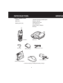
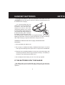
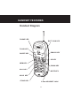
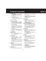
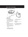
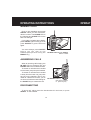
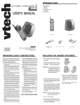
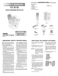
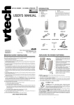
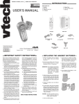
OWNER’S MANUAL
Ultra RangeMax
Model 1980
Custom manufactured for Ameritech
Customer service Departmemt Toll Free 800-456-6858
INTRODUCTION
•
Congratulations ! You have
purchased one of the best
performing cordless telephones on
the market!
•
•
The Ultra RangeMax digital
cordless telephone is a highly
integrated system that uses Direct
Sequence Spread Spectrum
Technology. One of more than 16
million possible digital security
codes is randomly selected every
time the handset is placed in the
base unit. The handset and base
will recognize each other based on
this security code, which minimizes
the chance of another cordless
phone using your telephone line.
Additionally, a digital scrambling
code is used during a conversation
to prevent voice code leakage in
the air.This scrambling code is
generated from 65,000 possible
combinations.
•
•
•
•
•
•
•
•
This manual is designed to
familiarize you with the Ultra
RangeMax. We strongly
recommend you read the manual
before using your phone.
OTHER SPECIAL
FEATURES ARE:
•
•
•
•
•
•
LOW BATTERY / OUT OF
RANGE INDICATOR
HEARING-AID COMPATIBLE
RECEIVER
EASY ANSWER - WHEN THE
P H O N E R I N G S S I M P LY
PRESS ANY KEY ON THE
HANDSET TO ANSWER
REMOVABLE BATTERY PACK
TOUCH TONE AND PULSE
DIALING
TEMPORARY TONE MODE
EARPIECE VOLUME CONTROL
RINGER VOLUME PRESET
HOLD
MUTE
2.5mm HEADSET JACK FOR
HANDS FREE OPERATION.
ONE TOUCH SPEED DIALING
FOR EMERGENCY#
20 NUMBER SPEED DIAL
MEMORY
20 CHANNELS OF OPERATION
A U T O M AT I C C H A N N E L
SEARCH AND SELECT
REDIAL FEATURE
4 PROGRAMMABLE RINGER
TYPES
1
INTRODUCTION
IMPORTAN
Parts Check List:
Handset Charging Cradle/Spare
Battery Charger
Telephone line cord
AC adaptor(x2)
Wall mounting adaptor
Belt Clip
Handset
Base unit
Battery pack (x2)
Base unit
Handset
Belt Clip
Telephone line cord
Battery pack(x2)
AC adaptor(x2)
Wall mounting adaptor
Handset Charging Cradle/Spare Battery Charger
2
IMPORTANT SAFETY INSTRUCTIONS
over a radiator or heat register.
This product should not be
placed in a built-in-installation
where proper ventilation is not
provided.
When using your telephone
equipment, basic safety
precautions should always be
followed to reduce the risk of fire,
electric shock and injury to
persons, including the following:
2. Follow all warnings and instructions marked on the product.
7. T h i s p r o d u c t s h o u l d b e
operated only from the type of
power source indicated on the
marking label. If you are not
sure of the type of power supply
to your home, consult your
dealer or local power company.
3. Unplug this product from the
wall outlet before cleaning. Do
not use liquid cleaners or
aerosol cleaners. Use a damp
cloth for cleaning.
8. Do not allow anything to rest on
the power cord. Do not locate
this product where the cord will
be abused by persons walking
on it.
4. Do not use this product near
water (for example, near a bath
tub, kitchen sink, or swimming
pool).
9. Never push objects of any kind
into this product through cabinet
slots as they may touch
dangerous voltage points or
short out parts that could result
in a risk of fire or electric shock.
Never spill liquid of kind on the
product.
1. Read and understand all
instructions.
5. Do not place this product on an
unstable cart, stand, or table.
The product may fall, causing
serious damage to the product.
10.To reduce the risk of electric
shock, do not disassemble this
product. If service or repair work
is required, contact Ameritech
Customer Service at 1-800-4566858. Opening or removing
cabinet parts other than
specified access doors may
expose you to dangerous
voltages or other risks. Incorrect
6. Slots and openings in the
cabinet and the back or bottom
are provided for ventilation. To
protect it from overheating,
these openings must not be
blocked by placing the product
on the bed, sofa, rug, or other
similar surface. This product
should never be placed near or
3
IMPORTANT SAFETY INSTRUCTIONS
covered by the operating
instructions because
improper adjustment of other
controls may result in damage
and will often require
extensive work to restore the
product to normal operation.
reassembling can cause electric
shock when the appliance is
subsequently used.
11.Do not overload wall outlets and
extension cords as this can
result in the risk of fire or electric
shock.
E.If the product has been
dropped and the cabinet has
been damaged.
12.Unplug this product from the
wall outlet:
F. If the product exhibits a
distinct change in
performance.
A.When the power supply cord
or plug is damaged or frayed.
B.If liquid has been spilled into
the product.
13.Avoid using a telephone (other
than a cordless type) during an
electrical storm. There may be
a remote risk of electric shock
from lighting.
C.If the product has been exposed
to rain or water
D.If the product does not operate
normally by following the
operating instructions. Adjust
only those controls that are
14.Do not use the telephone to
report a gas leak in the vicinity
of the leak.
SAVE THESE INSTRUCTIONS
4
HANDS
HANDSET BATTERIES
INSTALL THE BATTERY PACK
Install the battery pack
by sliding it on its track
upwards until it is firmly in
place.
Remove the battery
pack by pressing on the
lock knob and sliding
downward.
CHARGING THE HANDSET BATTERIES
The handset of your Ultra RangeMax cordless telephone is powered by
rechargeable batteries.The battery pack should be charged if:
• The phone produces a double beep
indicating a BATT LOW condition
when you press the ON/OFF key.
Beep,
Beep
PHONE
BATT LOW
ON/OFF
FLASH
MEM
HOLD
EMGCY
The phone double beeps when you
press ON/OFF
• The BATT LOW indicator is flashing.
PHONE
BATT LOW
• The handset seems completely dead
and does not beep when you press the The BATT LOW indicator is flashing.
keys.
5
GETTIN
HANDSET BATTERIES
To charge the batteries, place the handset in the base unit. The
CHARGING indicator will light to show the handset is seated properly and
the batteries are charging.
It is recommended that the
battery pack be charged initially for
24 hours. You can use your
telephone before that with
diminished capacity, but it is best
to let the battery pack charge fully.
To maximize the charge capacity of
the NiCad battery pack, recharge
the battery for several cycles. Once
you have properly conditioned the rechargeable battery, the maximum
battery life should be 4 hours of continuous talk time or 5 days of standby.
After initial charging, a typical maintenance charge is 8 hours.
CHA
NGE
IN USE
POW
ER
CHAN
GE
IN US
E
POWE
R
CAUTION: To reduce the risk of fire or injury, read and follow the
instructions.
1. Use only battery 80-4060-10-00.
2. Do not open or mutilate the battery. Released electrolyte is corrosive
and may cause damage to the eyes or skin. It may be toxic if swallowed.
3. Exercise care in handling batteries in order not to short the battery with
conducting materials such as rings, bracelets, and keys. The battery or
conductor may overheat and cause burns.
4. Do not dispose of the battery in a fire. The cell may explode.
IF THE BATTERIES DON’T RECHARGE
The battery pack can be recharged many times, but if you get a lowbattery signal even after 24 hours of charging, the battery pack should be
replaced.
6
GETTING STARTED
SETTING UP YOUR Ultra RangeMax
1. Choose an area near an electrical outlet and a telephone wall jack.
2. CHARGE THE HANDSET BATTERIES BEFORE USE.
The batteries recharge automatically whenever the handset is in the base
unit cradle. The batteries should be charged for 24 hours before using your
phone for the first time.
3. Plug the AC power adaptor into an electrical outlet and the DC connector
to the rear of the base.
7
DP TT
DP TT
4. Set the DP / TT switch on
the base unit. If you have
touch tone service on your
phone line, set the switch
to TT. If you have rotary
service, set the switch to
DP.
5. Once the battery pack is
fully charged, connect the
telephone line cord into the jack at the rear of the base unit. Plug the
other end into a telephone wall jack. Make sure the plugs snap securely
into place.
GETTING STARTED
6. CHECK FOR A DIAL TONE.
After the batteries are charged, rotate the base unit antenna to an upright
position.Next, pick up the handset and press the ON/OFF key. The PHONE
LED should light up, and you should hear a dial tone. If not, see IN CASE
OF DIFFICULTIES.
CAUTION:
1. Never install telephone wiring during a lighting storm.
2. Never install telephone jacks in a wet location unless the jack is specifically
designed for a wet location.
3. Never touch uninsulated telephone wires or terminals unless the
telephone line has been disconnected at the network interface.
4. Use caution when installing or modifying telephone lines.
8
WALL M
WAL
WALL MOUNTING
The Wall Mount adaptor is
designed to fit on standard Wall
Mount plates.
DP TT
1. CHOOSE A SPOT NEAR AN
ELECTRICAL OUTLET AND A
TELEPHONE JACK.
Your phone requires a modular
telephone jack and a standard
electrical outlet (120V AC). The
power cord is six feet long; make
sure there is an electrical outlet
within reach of the base. The outlet
should not be controlled by a wall
switch. If the switch is ever turned
off, the phone will not operate.
3. MOUNT THE BASE ON THE
WALL.
2. POSITION THE WALL MOUNT
ADAPTOR ON THE BASE.
Position the base so the
mounting screws will fit into the
holes on the bottom of the base.
Position the power cord to extend
down the wall the phone is to be
mounted on. Slide the base down
on the mounting screws until it
locks into place.
Attach the AC power adaptor
cord and the telephone line cord to
the wall bracket.
Line up the tabs on the wall
mount adapter with the holes on the
bottom of the base. Snap the wall
mount adaptor firmly in place.
Push in
and
slide down
9
WALL MOUNTING
HANDS
4. CONNECT THE TELEPHONE CORD.
The telephone line cord has a
snap-in plug at each end. Insert
one of the plugs into the jack on
the bottom of the base. Insert the
other end of the plug into the wall
jack.
5. CONNECT THE POWER CORD.
Plug the DC connector into the
DC jack at the rear of the base unit.
Plug the AC power adaptor into an
electrical outlet.
6. S E T T H E D I A L M O D E
SWITCH ON THE BASE UNIT.
If you have touch tone service on
your phone line, set the switch to
TT. If you have rotary service, set
the switch to DP.
10
HANDSET FEATURES
Handset Diagram
PHONE LED
BATT LOW LED
FLASH KEY
EMGCY KEY
ON/OFF KEY
PHONE
BATT LO
W
ON/OFF
MEM
RDL/P
MEM KEY
1
4
RDL/P KEY
GHI
7
PQRS
TONE
FLASH
EMGC
Y
HOLD
UP KEY
MUTE
2
ABC
3
DEF
5
JKL
6
MNO
8
TUV
0
OPER
9
DOWN KEY
WXYZ
#
MUTE KEY
HOLD KEY
*/TONE KEY
2.5mm HEADSET JACK
11
HANDSET FEATURES
PHONE LED
•
•
•
The PHONE LED lights when
the phone line is being used by
the handset.
It flashes during the
programming mode.
It flashes quickly when the
line is on hold.
•
•
•
The BATT LOW LED will flash
quickly when the handset
battery is getting low and needs
to be recharged.
It flashes slowly when the
handset is out of the talking
range or the base station is not
powered up.
The BATT LOW LED glows
steadily when MUTE is
activated.
ON/OFF KEY
•
Press the ON/OFF key to make
a call or end a call.
FLASH KEY
•
•
Press FLASH to switch
between calls when Call Waiting
signal is heard.
When in OFF mode, pressing
FLASH and a number key
(1,2,3,4) selects the ringer type.
MEM KEY
•
Used to store telephone
numbers in memory and
perform speed number dialing.
RDL/P KEY
•
When you hear the dial tone,
pressing the RDL/P key will dial
the last number that was called
on your phone.
It can also be used for a brief
PAUSE when programming
speed numbers.
HOLD KEY
•
BATT LOW LED
•
BASE U
•
When using your phone, press
HOLD to put a call on hold
To return to the call , press
PHONE or HOLD.
EMGCY KEY (EMERGENCY CALL)
•
One-touch speed dial number
which can be programmed for
an emergency # or any other
frequently dialed number.\
MUTE KEY
• When using your phone, press
MUTE to temporarily turn off
the microphone.
• To reactivate the microphone
press MUTE again.
UP KEY
•
•
Used to increase the earpiece
volume during a call
Used to increase the ringer
volume during OFF mode
DOWN KEY
•
•
Used to decrease the earpiece
volume during a call
Used to decrease the ringer
volume during OFF mode
* / TONE KEY
• In PULSE dialing mode, it is
used to switch to Temporary
Tone dialing mode
12
OPE
BASE UNIT FEATURES
Base Unit Diagram
CHAR
GE
IN USE
POW
ER
DP TT
DP/TT SWITCH
POWER LED
IN USE LED
CHARGING LED
CHARGING LED
•
The CHARGING LED
illuminates steadily when the
handset is in the base cradle to
indicate that the handset
battery is being charged.
•
The IN USE LED flashes quickly
when the call is on hold.
POWER LED
•
Lights when the base unit is
powered on
IN USE LED
•
•
Immediately after placing the
handset in the base cradle, the
IN U S E L E D f l a s h e s o n e
time to indicate that
initialization(assigning a new
security code and channel) is
completed
DP / TT (TONE/PULSE) SWITCH
•
The IN USE LED flashes slowly
when the handset is being used
or an incoming call is ringing.
13
Sets the phone to TT(TONE) or
DP (PULSE) dialing.
OPERATING INSTRUCTIONS
OPERAT
MAKING CALLS
Pick up the handset and press
ON/OFF. When you hear a dial tone,
dial the number. The PHONE LED on
the handset and IN USE LED on the
base unit will light.
If you make a mistake when dialing,
press ON/OFF again to hang up, then
press ON/OFF to get the dial tone
again.
You must always press ON/OFF
before you can dial on the
handset.(Except when using the
EMGCY key.)
PHONE
ON/OFF
CHAR
GE
IN USE
POWER
TO MAKE CALLS:Press ON/OFF
dial the number
ANSWERING CALLS
When an incoming call is ringing, the
IN USE LED on the base unit and
PHONE LED on the handset will flash.
To answer a call when the handset
is in the base, just pick up the handset.
To answer a call when the handset
is away from the base unit, just press
any key on the handset. This is very
useful in a dark environment; you do
not have to fumble around looking for
the ON/OFF key to answer the call.
PHONE
CHAR
GE
IN USE
POWER
TO ANSWER CALLS :
pick up the handset,
or press any key
DISCONNECTING
To end a call, either place the handset back in the base, or press
ON/OFF on the handset.
14
OPERATING INSTRUCTIONS
TEMPORARY TONE
If you have a rotary (dial-pulse) telephone service. (DP / TT switch is set
to DP), this feature allows you to enter special codes and tones to operate
answering machines, use electronic banking services, calling cards, or other
special services.
VT1980
PHONE
First , dial the call normally.
BATT LOW
ON/OFF
FLASH
MEM
HOLD
REDIAL
MUTE
EMGCY
1.Dial the call normall
4
Then activate the Temporary Tone feature
by pressing TONE (the *key).
7
O
JKL
GHI
TUV
9
OPER
#
PQRS
8
TONE
0
WXYZ
2.Press */TONE key
You can then press the numbers or
symbols you need, and your phone will
1
send the proper signals.
4
2
ABC
3
DEF
GHI
5
JKL
6
MNO
PQRS
8
TUV
9
WXYZ
TONE
0
OPER
#
7
To end the call , press ON/OFF or place
the handset back in the base unit. The
phone will automatically go back to rotary
(dial-pulse) service.
3.Phone is now in TONE mode.
If you have touch-tone service, (DP / TT switch set to TT), just dial normally.
This feature is only for rotary service telephone lines.
PROGRAMMING THE RINGER TYPE
The handset ringer is capable of four different types of ringing tones.
To program, the handset must be OFF.
15
OPERATING INSTRUCTIONS
To select a different ringer type do the
following:
1. Press FLASH
2. Press a key 1..4 to select a ringer type
A confirmation ring will be heard for the
new ringer type.
OPERAT
PHONE
BATT LOW
EMGCY
ON/OFF
FLASH
MEM
HOLD
RDL/P
MUTE
1
2
ABC
3
DEF
5
JKL
6
MNO
4
GHI
1.Press FLASH
2.Press a key 1..4
MEMORY DIALING (SPEED DIALING)
The Ultra RangeMax can store up to 21 different phone numbers that
you can dial simply by pressing MEM and the corresponding location code
(01-20), or simply by pressing the one-touch EMGCY key.
PROGRAMMING SPEED DIAL NUMBERS
The Handset must be OFF.
1. Press MEM. The PHONE LED will
blink to indicate that you are in the
programming mode.
2. Using the dial pad, enter the number
you want to store. The number can be up
to 16 digits long.
3. Press MEM once more.
4. Press the number of the memory
location you wish to store the number in
(01-20). If you wish to program EMGCY
memory , press EMGCY.
PHONE
BATT LOW
ON/OFF
FLASH
MEM
HOLD
RDL/P
MUTE
1
2
ABC
EMGCY
3
DEF
TO SPEED DIAL NUMBERS
Press MEM
Enter the number you want to store
Press MEM again
Enter the memory location
you wish to store
The phone now exits programming mode and emits two beeps.
16
OPERATING INSTRUCTIONS
SPEED NUMBER DIALING
PHONE
1. Press ON/OFF to get a dial tone.
BATT LOW
ON/OFF
FLASH
MEM
HOLD
REDIAL
MUTE
EMGCY
1.Press ON/OFF
980
PHONE
2. Press MEM and the memory location
number code (01-20).
For example, to dial the number you
assigned to location 18, you would press
ON/OFF, MEM, 1, 8.
BATT LOW
ON/OFF
FLASH
MEM
HOLD
REDIAL
MUTE
EMGCY
2.Press MEM
3.Enter memory location
EMERGENCY SPEED NUMBER DIALING (EMGCY key)
The EMGCY key is a dedicated speed dial key which is designed to be
used for emergency numbers, like 911, or for another frequently dialed
number. It is important to note that YOU MUST PROGRAM THE NUMBER
which will be dialed when you press EMGCY. THE MANUFACTURER
DOES NOT PRE-PROGRAM THIS NUMBER.
To dial using the EMGCY key you can simply press EMGCY on the
handset . The phone will automatically access dial tone, and dial the number
you have stored in the EMGCY location.
You can also dial the EMGCY number by pressing ON/OFF in
advance,and then press the EMGCY key.
TO CHANGE OR REPLACE A SPEED DIAL
NUMBER
To change or replace a stored number in speed dial, simply enter the
new number and store it in the memory location you wish to change.
17
OPERAT
OPERATING INSTRUCTIONS
STORING PAUSES IN MEMORY
To insert a pause in a phone number, press RDL/P at the appropriate
point when storing the number. This inserts a 2 second pause. For longer
pauses, press RDL/P two or more times. Each press makes the pause 2
seconds longer and is treated as a stored digit.
If your phone is connected to a PBX you can store the PBX access
number and a pause before the phone number.
For example, to store 9-PAUSE-5551234 in memory location 18, do the
following:
VT1980
PHONE
1. Press MEM
BATT LOW
ON/OFF
FLASH
MEM
HOLD
RDL/P
MUTE
EMGCY
2. Press 9
GHI
5
JKL
6
MNO
PQRS
8
TUV
9
WXYZ
TONE
0
OPER
#
4
7
RDL/P
MUTE
1
2
ABC
3
DEF
5
JKL
6
MNO
3. Press RDL/P
4
GHI
4. Press 5551234
RDL/P
MUTE
1
2
ABC
3
DEF
5
JKL
6
MNO
4
GHI
VT1980
PHONE
5. Press MEM
BATT LOW
ON/OFF
FLASH
MEM
HOLD
RDL/P
MUTE
EMGCY
2
ABC
3
DEF
GHI
5
JKL
6
MNO
PQRS
8
TUV
9
WXYZ
1
6. Press 1,8
4
7
18
OPERATING INSTRUCTIONS
USING REDIAL
The Ultra RangeMax cordless phone automatically stores the last number
you dialed in a special redial memory.
980
PHONE
To dial the number again,
press ON/OFF, to get dial tone.
BATT LOW
ON/OFF
FLASH
MEM
HOLD
REDIAL
MUTE
EMGCY
1.Press ON/OFF
RDL/P
MUTE
1
2
ABC
3
DEF
5
JKL
6
MNO
then press RDL/P.
The phone will automatically dial the number.
4
GHI
2.Press RDL/P
TO PUT A CALL ON HOLD
While using your phone, you can put a call on hold by pressing HOLD.
The PHONE LED on the handset will flash quickly to show a call is on hold.
To return to the call, press ON/OFF or HOLD again. If a call is on hold
using the Ultra RangeMax and the user picks up another phone on the
same line, the Ultra RangeMax will take itself off hold and turn off. Therefore,
you do not have to go back to turn the phone off if you go to another
extension. It is done automatically.
CHARG
E
IN USE
POWER
PRESS ON/OFF or HOLD (on the Ultra RangeMax(without CID)) to take
call off hold, or pick up another extension on the same line.
19
OPERATING INSTRUCTIONS
THE MUTE FEATURE
When you press MUTE while using
your phone, you can hear the caller’s
voice, but they cannot hear you. You
can use this feature to speak to
someone in the room without the caller
listening. While a call is muted the
BATT LOW LED on the handset will
be on.
T o go back to the two-way
conversation, press MUTE again.
PHONE
BATT LOW
ON/OFF
FLASH
MEM
HOLD
RDL/P
MUTE
EMGCY
Press MUTE
the caller can not hear your voice
PHONE
BATT LOW
ON/OFF
FLASH
MEM
HOLD
RDL/P
MUTE
EMGCY
Press MUTE to return
to the two-way conversation
VOLUME CONTROL
During a call, press the( ) UP or( )
DOWN keys to increase or decrease
the earpiece volume. Three rapid
beeps will be heard when you reach
the highest or lowest volume level.
PHONE
BATT LOW
ON/OFF
FLASH
MEM
HOLD
RDL/P
MUTE
EMGCY
UP ( ) and DOWN ( ) keys control
earpiece volume during a call
TO PRESET THE RINGER VOLUME
The Ultra RangeMax has two ringer
volume levels. To preset the ringer
volume, the phone must be OFF. Press
the ( )UP or( ) DOWN keys, a
confirmation ring will be heard for the
new ringer volume level.
20
PHONE
BATT LOW
ON/OFF
FLASH
MEM
HOLD
RDL/P
MUTE
EMGCY
UP ( ) and DOWN( ) keys preset
ringer volume when phone is OFF
HANDSET CHARGING CRADLE
/SPARE BATTERY CHARGER
A Handset Charging Cradle/Spare Battery Charger is available for use
with the Ultra RangeMax(without CID).
This allows the user to remotely charge a Spare Battery and Handset
while it is away from the Base Unit.
SETTING UP THE HANDSET CHARGING
CRADLE /SPARE BATTERY CHARGER
1. Choose an area near an electrical outlet.
2. Plug the AC power adaptor into an electrical outlet and the DC connector
into the bottom of the charger.
3. Place the Spare Battery in the
charging slot.The Spare Battery LED
will glow steadily.
4. Place the Handset in the charging
base.The Handset Charging LED will
glow steadily.
21
HEADSET INSTALLATION
AND OPERATING INSTRUCTIONS
Your Ultra RangeMax(without
CID) cordless telephone is
equipped with a 2.5mm Headset
Jack for use with an optional
accessory Headset or hands-free
operation.
If you choose to use the Headset
option, you must do the following:
The Ultra RangeMax(without
CID) is also equiped with a
detachable belt clip. Align the pins
on the inside edge of the belt clip
with the notches on the side of the
Ultra RangeMax(without CID)
Handset. The belt clip should snap
securely into place. Do not force
the connection. See Illustration.
INSTALLATION
Obtain an optional accessory
Headset, which is compatible with
the Ultra RangeMax(without
CID).
Once you have a compatible
2.5mm Headset, locate the
Headset Jack on the Handset of
your Ultra RangeMax(without
CID). Connect the plug on the
Headset to the jack on the cordless
Handset. The plug should fit
securely. Do not force the
connection. See illustration.
OPERATION
Note: whenever a compatible
Headset is connected to the
cordless Handset, the microphone
on the Handset will be MUTED.
This is done to limit the effect of
background noise.
The following operational
characteristics apply to most
Headsets. The same may also
apply to other compatible
headsets, but assumes no
responsibility for their performance.
22
HEADSET INSTALLATION
AND OPERATING INSTRUCTIONS
The headset has a monaural
design which is reversible, so you
can wear your Headset on either
the left or right ear, leaving one ear
free for room conversation.
For maximum sound quality, the
flexible microphone should be
positioned at the corner or your
mouth, about one inch from your
face.
ONE
INCH
ON RIGHT EAR
ON LEFT EAR
The headband can be adjusted
to fit the contour of your head.
Using both hands, slide the
headband up or down so that it
rests comfortably on your head with
the speaker cushion centered
against your ear.
23
IN CASE
MAINTENANCE
TAKING CARE OF YOUR TELEPHONE
Your Ultra RangeMax cordless telephone contains sophisticated
electronic parts so it must be treated with care.
AVOID ROUGH TREATMENT
Place the handset down gently. Save the original packing material to
protect your telephone if you ever need to ship it.
AVOID WATER
Your telephone can be damaged if it gets wet. Do not use the handset
outdoors in the rain, or handle it with wet hands. Do not install your base
unit near a sink, bathtub or shower.
ELECTRICAL STORMS
Electrical storms can sometimes cause power surges harmful to electronic
equipment.
For your own safety, use caution when using electric appliances during
storms.
CLEANING YOUR TELEPHONE
Your telephone has a durable plastic casing that should retain its luster
for many years. Clean it only with a soft cloth slightly dampened with water
or a mild soap. Do not use excess water or cleaning solvents of any kind.
24
IN CASE OF DIFFICULTIES
If you have difficulty operating your phone, the suggestions below should
solve the problem. If you still have difficulty after trying these suggestions,
call:
Ameritech Customer Service of 1-800-456-6858
Problem
Remedy
THE PHONE DOESN’T
WORK AT ALL
•
•
NO DIAL TONE
•
•
First check all the suggestions above.
If you still don’t hear a dial tone,
disconnect the base unit from the
telephone jack and connect a different
phone. If there is no dial tone on that
phone either, the problem is in your
wiring or local service. Call your local
telephone company.
YOU GET NOISE,
STATIC, OR A WEAK
SIGNAL EVEN WHEN
YOU’RE NEAR THE
BASE UNIT
•
Place the handset in the base
momentarily to reset the security code.
Then press ON/OFF to get a line.
Household appliances plugged into the
same circuit as the base unit can
sometimes cause interference. Try
moving the appliance or the base unit
to another outlet.
Make sure the power cord is plugged in.
Make sure the telephone line cord is
plugged firmly into base unit and the
telephone wall jack.
• Make sure the batteries are properly
charged. If the BATT LOW LED is on,
the battery needs charging. If the
PHONE LED does not light when you
press ON/OFF, you must charge the
batteries.
• If you recently installed a new battery
pack, make sure it is installed correctly.
•
25
IN CASE OF DIFFICULTIES
Problem
Remedy
YOU GET NOISE,
STATIC, OR A WEAK
SIGNAL WHEN YOU’RE
AWAY FROM THE BASE
UNIT
•
THE HANDSET DOES
NOT RING WHEN YOU
RECEIVE A CALL
•
•
•
•
You may be out of range. Either move
closer to the base, or relocate the base
unit.
The layout of your home may be limiting
the range. Try moving the base unit to
the second or third floor, or to some other
location.
Make sure the telephone line cord is
plugged firmly into the base unit and the
telephone jack. Make sure the power
cord is plugged in.
You may be too far from the base unit.
You may have too many extension
phones on your telephone line to allow
them all to ring. Try unplugging some of
the other phones.
YOUR CALLER FADES
IN AND OUT
•
You may be nearly out of range. Move
closer, or relocate the base.
YOU HEAR OTHER
CALLS WHILE USING
YOUR PHONE
•
Replace the handset in the base cradle,
wait a few moments and try again.
Disconnect your base unit from the
telephone jack, and plug in a regular
telephone. If you still hear other calls,
the problem is probably in your wiring or
local service. Call your local telephone
company.
YOU HEAR NOISE IN THE
HANDSET, AND NONE OF
THE KEYS OR BUTTONS
WORK
•
•
•
Make sure the power cord is plugged in.
Your base unit and handset may not be
operating on the same channel or
security code. Place the handset in the
cradle for a few moments to reload the
security code and reset the channel.
26
IN CASE
IN CASE OF DIFFICULTIES
Problem
COMMON CURE FOR
ELECTRONIC
EQUIPMENT
Remedy
Electronics , like people , can sometimes
get confused. If the unit does not seem to
be responding normally, then try putting the
handset in the cradle for 5 to 10 seconds to
re-initialize the unit. If it still does not seem
to respond, perform the following steps (in
the order listed):
1. Disconnect the power to the base.
2. Disconnect the handset battery.
3. Wait a few minutes.
4. Connect power to the base.
5. Connect the handset battery.
6. Put the handset in the base to re-initialize.
27
WARRANTY STATEMENT
The Manufacturer warrants, to
the original purchaser only, the
material and workmanship of this
product for ONE YEAR from the
date of purchase. The
manufacturer will repair or replace,
at our option, this product without
charge should it fail due to a defect
in material or workmanship within
that time period.
This warranty does not apply to
loss or damage which is the result
of accident, misuse or negligence.
All other warranties, expressed,
implied, or statutory, including
warranties of fitness for a particular
purpose, are limited to the time
period listed and are otherwise
excluded from this warranty. The
manufacturer may, at its option,
void the warranty if unauthorized
repairs are attempted. Additionally,
the manufacturer shall not be liable
for any incidental or consequential
damage or commercial loss, nor for
any other loss or damages.
The manufacturer assumes no
responsibility for products sent
without prior Return Authorization.
To arrange for service, in or out
o f w a r r a n t y, p l e a s e c a l l
AMERITECH at 1-800-456-6858.
28
FCC RE
FCC REGULATIONS
This equipment complies with
Part 15 and 68 of the Federal
Communications Commission
(FCC) rules for the United States.
A label is located on the
underside of the base unit
containing either the FCC
registration number and Ringer
Equivalence Number (REN). You
must, upon request, provide this
information to your local telephone
company.
This equipment is compatible
with inductively coupled hearing
aids.
Should you experience trouble
with this telephone equipment,
please contact:
Ameritech Customer Service at
1-800-456-6858
for repair / warranty information.
The telephone company may ask
you to disconnect this equipment
from the line network until the
problem has been corrected.
Yo u r U l t r a R a n g e M a x i s
designed to operate at the
maximum power allowed by the
FCC. This means your handset and
base unit can communicate only
over a certain distance - which will
depend on the location of the base
unit and handset and layout of your
home or office.
FCC RE
FCC PART 15
The equipment has been tested
and found to comply with part 15
of the FCC rules. These limits are
designed to provide reasonable
protection against harmful
interference in a residential
installation. This equipment
generates, uses and can radiate
radio frequency energy and, if not
installed and used in accordance
with the instructions, may cause
harmful interference to radio
communications. However, there is
no guarantee that interference will
not occur in particular installation.
If this equipment does cause
harmful interference to radio or
television reception, which can be
determined by turning the
equipment off and on, the user is
encouraged to try and correct the
interference by one or more of the
following measures:
- Reorient or relocate the
receiving antenna.
- Increase the separation between
the equipment and receiver.
- Connect the equipment into an
outlet or on a circuit different
from that to which the receiver
is connected.
- Consult the dealer or an
experienced radio / TV
technician for help.
29
FCC REGULATIONS
FCC PART 68
The FCC requires that you
connect your cordless telephone to
the nationwide telephone network
through a modular telephone jack
(USOC, RJ11C or RJ11W)
Your telephone company may
discontinue your service if your
equipment causes harm to the
telephone network. They will notify
you in advance of disconnection, if
possible. During notification, you
will be informed of your right to file
a complaint with the FCC.
Occasionally your telephone
company may make changes in its
facilities, equipment, operation, or
procedures that could affect the
operation of your equipment. If so,
you will be given advance notice
of the change to give you an
opportunity to maintain
uninterrupted service.
telephone equipment can only be
made by the manufacturer or its
authorized agents or by others who
may be authorized by the FCC. For
repair procedures, follow the
instructions outlined under the
Limited Warranty.
This equipment may not be used
on coin service provided by the
phone company or Party lines.
The REN is useful in determining
the number of devices you may
connect to your telephone line and
still enable the devices to ring when
you receive a call. The general rule
is that the REN value should not
exceed 5.0A total; however,
contact your local telephone
company for the specific number in
your area.
The base unit contains no user
serviceable parts. The handset
contains a user replaceable battery
pack.
If it is determined that your
telephone equipment is malfunctioning,
the FCC requires that it not be used
and that it be unplugged from the
modular jack until the problem has
been corrected. Repairs to this
30
TECHN
TECHNICAL SPECIFICATIONS
FREQUENCY
CONTROL
Crystal Controlled PLL Synthesizer
TRANSMIT
FREQUENCY
902 MHz to 928 MHz
(All twenty channels within this
range)
SIZE
Handset : 18.5cm x 6.3cm x 3.6cm
(L x W x T) maximum
(antenna excluded)
Base
: 20.5cm x 18.5cm x 5.5cm
(L x W x T) maximum
(antenna excluded)
ANTENNA LENGTH
RECEIVE
FREQUENCY
Handset : 6 cm
Base
: 12 cm
902 MHz to 928 MHz
(All twenty channels within this
range)
WEIGHT
NOMINAL EFFECTIVE
RANGE
Maximum power allowed by
FCC. Actual operating range may
vary according to environmental
conditions at the time of use.
Handset : 250 grams
Base
: 520 grams
Batteries: 50 grams
POWER REQUIREMENTS
Handset : Self-contained nickel
cadmium rechargeable battery
supply, 3.6V nominal, 600mAh
capacity.
Power Adapter :DC 9V @500mA
SPECIFICATIONS ARE TYPICAL AND MAY CHANGE WITHOUT NOTICE
31
Table of Contents
INTRODUCTION .................................................................. 1
Parts Check List: ................................................................................................ 2
IMPORTANT SAFETY INSTRUCTIONS ............................. 3
HANDSET BATTERIES ....................................................... 5
GETTING STARTED ........................................................... 7
WALL MOUNTING .............................................................. 9
HANDSET FEATURES ...................................................... 11
Handset Diagram .............................................................. 11
PHONE LED .........................................................................................
BATT LOW LED ...................................................................................
ON/OFF KEY ........................................................................................
FLASH KEY ..........................................................................................
MEM KEY ..............................................................................................
RDL/P KEY ...........................................................................................
HOLD KEY ............................................................................................
EMGCY KEY (EMERGENCY CALL) ....................................................
MUTE KEY ............................................................................................
UP KEY .................................................................................................
DOWN KEY ...........................................................................................
* / TONE KEY ........................................................................................
12
12
12
12
12
12
12
12
12
12
12
12
BASE UNIT FEATURES .................................................... 13
Base Unit Diagram ..............................................................................
CHARGING LED ...................................................................................
IN USE LED ..........................................................................................
POWER LED .........................................................................................
13
13
13
13
DP / TT (TONE/PULSE) SWITCH ........................................................ 13
OPERATING INSTRUCTIONS .......................................... 14
MAKING CALLS .................................................................................... 14
ANSWERING CALLS ............................................................................ 14
DISCONNECTING ................................................................................ 14
TEMPORARY TONE ............................................................................. 15
PROGRAMMING THE RINGER TYPE ................................................. 15
MEMORY DIALING (SPEED DIALING) ................................................ 16
PROGRAMMING SPEED DIAL NUMBERS ......................................... 16
SPEED NUMBER DIALING .................................................................. 17
EMERGENCY SPEED NUMBER DIALING(EMGCY key) .................... 17
TO CHANGE OR REPLACE A SPEED DIAL NUMBER ....................... 17
STORING PAUSES IN MEMORY ......................................................... 18
USING REDIAL ..................................................................................... 19
TO PUT A CALL ON HOLD .................................................................. 19
THE MUTE FEATURE .......................................................................... 20
VOLUME CONTROL ............................................................................ 20
TO PRESET THE RINGER VOLUME .................................................. 20
HANDSET CHARGING CRADLE/SPARE BATTERY CHARGER .......... 21
HEADSET INSTALLATION AND
OPERATING INSTRUCTIONS .................................................... 22
MAINTENANCE ................................................................. 24
IN CASE OF DIFFICULTIES ............................................. 25
WARRANTY STATEMENT ................................................ 28
FCC REGULATIONS ......................................................... 29
TECHNICAL SPECIFICATIONS ....................................... 31
Copyright 1998 for VTECH COMUNICATIONS LTD.
91-4007-42-00
ISSUE 0