1
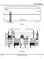
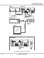
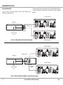
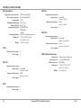
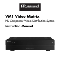
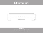
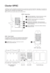
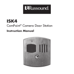
VM1 Video Matrix
HD Component Video Distribution System
Installation Manual
SAFETY INSTRUCTIONS
WARNING: TO REDUCE THE RISK OF FIRE
OR ELECTRIC SHOCK, DO NOT EXPOSE THIS
APPLIANCE TO RAIN OR MOISTURE.
CAUTION: TO REDUCE THE RISK OF ELECTRIC
SHOCK, DO NOT REMOVE THE COVER. NO USERSERVICEABLE PARTS INSIDE. REFER SERVICING
TO QUALIFIED SERVICE PERSONNEL.
The lightning flash with arrowhead symbol, within an
equilateral triangle, is intended to alert the user to the
presence of uninsulated dangerous voltage within the
product’s enclosure that may be of sufficient magnitude
to constitute a risk of electric shock to persons.
The exclamation point within an equilateral triangle is
intended to alert the user to the presence of important
operating and maintenance (servicing) instructions in the
literature accompanying the appliance.
Safety Instructions
1. Read Instructions - All the safety and operating
instructions should be read before the appliance is
operated.
2. Retain Instructions - The safety and operating
instructions should be retained for future reference.
3. Heed Warnings - All warnings on the appliance in the
operating instructions should be adhered to.
4. Follow Instructions - All operating and user
instructions should be followed.
5. Water and Moisture - The appliance should not
be used near water; for example, near a bathtub,
washbowl, kitchen sink, laundry tub, in a wet
basement, or near a swimming pool. The apparatus
shall not be exposed to dripping or splashing liquids
and no objects filled with liquids, such as vases, shall
be placed on the apparatus.
2
6. Carts and Stands - The appliance
should be used only with a cart or
stand that is recommended by the
manufacturer. An appliance and cart
combination should be moved with
care. Quick stops, excessive force
and uneven surfaces may cause the
appliance and cart combination to overturn.
7. Location of the Amplifier - Do not mount this unit
under a kitchen cabinet. Do not expose the amplifier
to direct sun light or heating units as the amplifier
internal components’ temperature may rise and
shorten the life of the components. Avoid damp and
dusty places.
8. Ventilation - The appliance should be situated so
that its location or position does not interfere with
its proper ventilation. For example, the appliance
should not be situated on a bed, sofa, rug, or similar
surface that may block the ventilation openings, or
placed in a built-in installation, such as a bookcase or
cabinet that may impede the flow of air through the
ventilation openings.
9. Heat - The appliance should be situated away from
heat sources such as radiators, heat registers, stoves,
or other appliances (including amplifiers) that
produce heat.
10. Power Sources - The appliance should be connected
to a power supply only of the type described in
the operating instructions or as marked on the
appliance.
11. Grounding or Polarization - Precaution should be
taken so that the grounding or polarization means of
an appliance is not defeated.
12. Power Cord Protection - Power supply cords should
be routed so that they are not likely to be walked
on or pinched by items placed upon or against
them, paying particular attention to cords at plugs,
receptacles, and the point where they exit from the
appliance.
Russound VM1 Installation Manual
13. Main Power Disconnect - The power switch is a singlepole switch. When the switch is in the “Off” position,
the appliance is not completely disconnected from
the main power. The main power plug is used as the
disconnect device and shall remain readily operable.
When installing the product, ensure that the plug is
easily accessible.
14. Cleaning - The appliance should be cleaned only as
recommended by the manufacturer.
15. Non-Use Periods - The power cord of the appliance
should be unplugged from the outlet when left
unused for a long period of time. To remove all power
(supply mains) from the appliance, remove the plug
from the wall outlet.
16. Object and Liquid Entry - Care should be taken so
that objects do not fall and liquids are not spilled into
the enclosure through the openings.
17. Servicing - The user should not attempt to service the
appliance beyond that described in the operating
instructions. All other servicing should be referred to
qualified service personnel.
18. Damage Requiring Service - The appliance should be
serviced by qualified service personnel when:
A.The power supply cord or the plug has been
damaged.
B. Objects have fallen, liquid has been spilled into
the appliance; C.The appliance has been exposed to rain; or
D.The appliance does not appear to operate
normally; or
E. The appliance has been dropped or the enclosure is damaged.
Rev. 1
TABLE OF CONTENTS
Product Overview ................................................................................................................... 4
Front and Rear Panels............................................................................................................. 5
Control Methods....................................................................................................................... 6
Upconverter Configuration.................................................................................................. 7
VM1 Configuration Tool......................................................................................................... 8
Installation.................................................................................................................................. 9
Rack Mounting.......................................................................................................................... 9
Wiring and Connections........................................................................................................ 9
Status Indication....................................................................................................................... 9
Russound Application Diagram........................................................................................10
RS232 Application Diagram................................................................................................11
Linking Multiple VM1s..........................................................................................................12
Troubleshooting Guide........................................................................................................13
Technical Specifications.......................................................................................................14
Warranty....................................................................................................................................15
Rev. 1
Russound VM1 Installation Manual
3
product OVERVIEW
Introduction
The VM1 Video Matrix works with a multiroom audio system to distribute
analog component video over a single CAT-5e cable to each zone. Capable of
handling high-definition component video signals, it also provides conversion
of composite and S-video signals in optional configurations. Designed for
use with Russound RNET® multiroom solutions, the VM1 provides seamless
integration with the Russound ACA-E5, MCA-C5, CAA66, CAM6.6, and CAV6.6
systems. It also works with other systems through serial control (RS232, USB).
The Video Matrix is not IR controllable.
The upconverter (UC and UC2) configurations convert S-video and composite
video signals to component video for distribution while maintaining the
original source resolution. The benefit is that the user doesn’t have to select
a composite or S-video input on the display to view the sources. The UC
configurations of the Video Matrix provide conversion for sources 1 and 4. The
UC2 configuration provides conversion for sources 1, 4, 5, and 8. All upconverter
configurations provide mini-DIN connectors for S-video signals and RCA
connectors for composite video signals. Internal switches allow the installer to
select which inputs are used, whether composite, S-video, or component.
The VM1 has a rack-mountable 2U chassis (rack ears included) and uses a
24VDC power supply (also included). A red LED on the front panel indicates
the power state of the VM1. It glows steadily to indicate power on and blinks
to indicate an error in powering up. A green LED blinks to indicate control data
traffic on the serial bus.
The VM1 Video Matrix Configuration Tool Software allows installers to
customize the VM1 Video Matrix for a much wider variety of applications. It
allows the dealer to assign VM1 inputs to specific system sources and VM1
outputs to specific system zones.
Video Resolution
VMR1 Receiver
The Video Matrix system is capable of high-definition resolution up to 1080p.
However, the signal resolution of the HD sources must be compatible with
the connected displays. Thus, if any display connected to the Video Matrix is
limited to 480p, that output resolution must be selected on each connected
source, unless the display has the ability to scale the image down from a higher
resolution. Otherwise the image will not display properly.
The VMR1 Receiver is a single-gang in-wall device that installs in each room
where component video distribution is desired. It receives the video signal
from the VM1 through a single CAT-5e cable and provides red, green, and blue
RCA jacks for direct connection to the display with an RGB video cable.
VM1 Configuration Software
VM1 Configurations
The Video Matrix is available in five configurations:
VM1 4 – Provides basic 4x4 switching from analog component video sources.
VM1 4UC – Provides 4x4 component video switching with one upconverter.
VM1 8 – Provides basic 8x8 switching from analog component video sources.
VM1 8UC – Provides 8x8 component video switching with one upconverter.
VM1 8UC2 – Provides 8x8 component video switching with two
upconverters.
The 4x4 configurations provide four source inputs and four zone outputs. The
8x8 configurations provide eight source inputs and eight zone outputs. Each
source input has red, green, and blue RCA connectors for component video
signals. Each zone output has an RJ45 8-pole modular connector for a CAT-5e
cable, which feeds an in-wall VMR1 receiver at the zone’s display location.
4
Russound VM1 Installation Manual
Rev. 1
front and Rear Panel
Power LED
Data traffic LED
VM1 Front Panel
RS232 DB9 serial control port
RNET RJ45 ports
Source inputs 1-4
USB Type B serial control port
Zone outputs 1-4
Optional Upconverter inputs for
S-video and composite video sources
Power supply input Source inputs 5-8
Power switch
Zone outputs 5-8
VM1 8UC2 Rear Panel
Rev. 1
Russound VM1 Installation Manual
5
control methods
The Video Matrix is controlled by the system to which it is connected. It
switches video sources to the zones by receiving source selection commands
from the host system.
The VM1 provides a choice of ports for receiving control data from the host
system: two RJ45 jacks for linking to a Russound RNET-enabled multiroom
system; a DB9 serial connector; and a USB connector.
The VM1 offers three control options:
• RNET via RJ45 modular ports
• RS232 via DB9 port
• RS232 via USB port*
RNET communication
When connected through the RNET port, a VM1 8 Video Matrix default
configuration monitors the RNET system’s communication bus and responds
to source selection events for sources 1 through 8 from zones 1 through 8. (In
a system with multiple six-zone controllers, zones 7 and 8 are zones 1 and 2 on
controller 2.) With the CAV6.6 system, it also responds to selection of the Front
(Aux) A/V Input (source 7). This permits the Video Matrix to distribute that
source instead of running a separate video cable from the source to the display
and selecting it at the display. The 4x4 configurations of the VM1 respond to
source selection commands for sources 1 through 4 by default. Source inputs
can be assigned to other system specific sources using the VM1 Configuration
Tool software.
RS232 communication
The DB9 serial port allows control of the Video Matrix from a home automation
and control system such as AMX or Crestron. In this application, the VM1 uses
RS232 command strings for source selection. The RS232 command protocol for
the VM1 is available from the Document Center at www.russound.com.
USB communication
The USB port is for control devices that do not have DB9 legacy connections.
It uses the same RS232 command strings as the DB9 port.
*For third-party control of the VM1 through a USB interface, you must install
the necessary Russound USB drivers on a PC.
6
Russound VM1 Installation Manual
Rev. 1
upconverter configuration
Upconverter Configuration
1. Turn off the power switch.
Models with upconverters are factory set for composite video. For S-video or
component, follow the procedure below to set the input switches as needed
before installing the VM1 (see diagram).
2. Unplug the power supply from the VM1 chassis.
CAUTION: This procedure is for qualified personnel only. To reduce
the risk of electric shock, do not perform this procedure unless you are
qualified to do so.
3. Remove the 9 cover screws on the rear and sides.
4. Pull the cover up off the chassis, lifting one side first and then the other.
5. Set the switches as shown in the table below.
6. Replace the cover and screws.
Upconverter input DIP switch settings
Component
1 2 3 4
Composite
1 2 3 4
S-video
1 2 3 4
Off
Off
Off
1 2 3 4
1 2 3 4
1 2 3 4
For Sources 1 and 4
For Sources 5 and 8
Component
1 2 3 4
Composite
1 2 3 4
S-video
1 2 3 4
Off
Off
Off
1 2 3 4
1 2 3 4
1 2 3 4
Off
Off
Off
Source 5
Source 1
Source 8
Source 4
Off
Off
Off
Required DIP switch positions shown in black
Required DIP switch positions shown in black
Back panel of VM1
Top view of VM1 8UC2 interior showing upconverter
input switch locations
Rev. 1
Russound VM1 Installation Manual
7
VM1 configuration tool software
Overview
The VM1 Video Matrix Configuration Tool Software allows you to assign VM1
inputs to specific system sources and VM1 outputs to specific system zones.
This free download is available through Russound's Document Center under
Video Distribution.
Requirements
This software requires VM1 Version 2.00.00 Firmware or higher to work. The
latest firmware version with update instructions is posted on Russound’s
Document Center.
Configuration Tool Summary
zones for source selection changes. This allows flexibility for using the VM1
with sources/zones that have different video distribution requirements. This
even allows multiple VM1 outputs to be assigned to the same zone of the
audio controller when there are multiple displays in one audio zone.
Factory Init:
This sets the VM1 back to the factory default settings based on the VM1
model selected.
Send Configuration to VM1:
This performs the write function to the VM1 to load configuration settings.
The following information corresponds to the fields available from the
configuration software main screen.
COM Port Selection:
This selection determines what COM port the PC will be using for
communication to the VM1 (can be configured through USB or serial port).
VM1 Model:
The VM1 model selection determines how many video matrix inputs and
outputs can be configured.
Controller Model:
The Controller model selection determines how many audio sources there
can be and how many zones are on each controller.
VM1 Input Assignment:
Each source of the audio system is represented on the left side while a
corresponding combo box is located to its right for selecting the input on the
VM1 to be associated with that audio source.
Select what input on the VM1 is assigned to what source on the audio
controller. This allows a VM1-4 four source four zone video matrix to support
video for any four system source inputs, not just 1-4. This also resolves
situations where a particular source is not for video as with the CAM6.6T which
has an AM/FM tuner for source #1. Additionally, multiple sources on the audio
system can be assigned to the same video input on the VM1, if they share a
common video signal (e.g., SMS3).
Controller and Zone Output Assignment:
Assign each output on the VM1 to correspond with particular audio controller
8
Russound VM1 Installation Manual
Rev. 1
installation
Location
Locate the VM1 Video Matrix with the host system controller and source
equipment to facilitate source and control connections. Locate the VMR1
Receivers near the video displays in the zones, within 300 feet (90 m) of the
VM1.
3.Connect Receiver cables to VM1. Crimp RJ45 connectors on the system
end of the CAT-5e cables, following the T568A standard as shown. Plug the
connectors into the appropriate zone outputs on the VM1. (If using wall
plates, punch down the CAT-5e per the T568A standard and use straightthrough patch cables between the VM1 and the wall plates.)
Rack Mounting
+
+
VM1 Chassis side view
Rack mounting
flange
Wiring and Connections
The Video Matrix handles all the video switching for the multiroom system.
The following steps apply to wiring and connections for video only.
Note: Turn the VM1 power switch off and unplug the power supply from the
wall receptacle before making any connections.
1.Run cable. Install lengths of CAT-5e cable up to 300 feet (90 m) between the
VM1 and the video display locations in the zones. If desired, use modular
wall plates and RJ45 patch cables at the VM1 for a neater appearance.
Note: When running CAT-5e cables, avoid AC power wiring. If you have to
run the cables parallel to electrical wiring, space the cable at least 12 inches
(30 cm) from AC power lines.
2.Connect VMR1 Receivers. In each
zone, punch down the CAT-5e
cable on the back of the VMR1 as
indicated on the circuit board, using
the proper 110 punchdown tool to
avoid damage..
Rev. 1
RJ-45 Using T568A
Wiring Standard
Rack ear
+
To rack mount the VM1, attach
the supplied rack ears to the
chassis as shown. Leave one rack
unit of space open above and
below the VM1 to allow proper
ventilation of the chassis. Do not
mount the VM1 above a device
that produces high amounts of
heat, such as an amplifier.
4.Connect video sources. Use video patch cables to connect from the source
component outputs to the source inputs on the VM1. Note: Each source
input with an upconverter can use either the S-video, composite video, or
component video input. Set the internal switches to the correct format for
each source (see page 7).
5.Connect VM1 to system. Use the appropriate cable to connect the VM1 to
the multiroom or home automation system.
RNET Connection: With the RNET-enabled multiroom system turned off, use
a straight-through RJ45 patch cable to connect from either RNET port on the
VM1 to any unused RNET Link port on the system or a connected RNET-enabled
source component. When powering up the system, turn on the VM1 and other
RNET-enabled peripheral devices before turning on the RNET multiroom
system. This allows the system to recognize the VM1 and peripheral devices.
RS232 Connection: Use a DB9 serial data cable to connect from the DB9 port
on the VM1 to a similar port on the home control or automation system.
USB Connection: Use a USB Type B to Type A cable to connect from the USB
port on the VM1 to a USB port on the computer or control system.
Status Indication
The red front-panel LED glows steadily to indicate the power is on. It blinks if
there is a power-up error. The green LED blinks to indicate control data traffic
on the serial bus.
Russound VM1 Installation Manual
9
russound aPplication diagram
Example 2
Example 1
RGB cable
Video display - Zone 4
RGB cable
DVD player
VMR1 Receivers
VM1 Video Matrix
Audio to controller
Power supply
CAT-5e cables
RJ45 patch cable
SMS3 Smart Media Server
CAT-5e cables
VM1 Video Matrix
Power supply
VGA-component
video adapter
RGB cable
Video display
VGA IN
RCA cables
MCA-C5 Multiroom Controller
RJ45 cable
RCA cable
RJ45 patch cable
Video cable
RGB cable
RGB cable
VMR1 Receivers
Audio to
controller
VGA serial cable
DVD player - Source 1
SMS3 Smart Media Server - Sources 2, 3, 4
RJ45 patch cable
MCA-C5 Multiroom Controller
Audio from sources
RNET control of VM1in multiroom system
(SMS3 composite video with upconversion)
RNET control of VM1in multiroom system
(SMS3 VGA / component video)
Connection for RNET control by a multiroom audio system
10
Russound VM1 Installation Manual
Rev. 1
RS232 aPplication diagram
Connection for RS232 control by a home automation system
Rev. 1
Russound VM1 Installation Manual
11
linking Multiple vm1s
Linking Multiple VM1s
Up to 6 VM1s can be linked together to provide high definition video
distribution to additional zones.
The video output of the sources will need to be split to both VM1s. This can
be done passively with a cable splitter or actively with a video distribution
amplifier.
VM1 Video Matrix #1
DVD player
RGB patch cable
Cable splitter
Audio to controller
Source 1
Passive - Cable splitter used to split video output
VM1 Video Matrix #2
VM1 Video Matrix #1
DVD player
RGB patch cables
VM1 Video Matrix #2
Audio to controller
Source 1
Video
distribution
amplifier
Active - Video distribution amplifier used to split video output
12
Russound VM1 Installation Manual
Rev. 1
troubleshooting guide
No Hot Swap for VMR1
For All VM1-4UC and VM1-8UC Users
DO NOT UNPLUG VMR1 RECEIVERS WHILE VM1 AND TV ARE POWERED ON: The
power for the VMR1 receiver’s grounds through the television it is connected
to. The television’s video input can be damaged if the VMR1 receiver’s are “Hot
Swapped. “ Please insure that the television and the VM1 are powered off
before the VMR1 is connected or disconnected.
Sources 1 and 4 and 5 and 8 are factory defaulted for composite video. To use
component or S-Video inputs, the internal switches must be changed. Please
refer to page 7 for this procedure.
For New VM1 Set-Up
A new VM1 outputs Source 1 video to all zones. When testing, turning the
system Party Mode on can help troubleshoot "no video" issues.
Troubleshooting Guide
PROBLEM
CAUSE
ACTION
Loss of picture / VM1 is
clicking
Bad power supply or wrong power supply is being used
Check to insure that the A-PS power supply (24 volts) is connected. Test power
supply for 24 volts
Red (Pr) and Blue (Pb) colors
are reversed
RJ 45 connector is wired to T568B standard
Rewire the RJ45 connector to the T568A standard
No picture
Video Sync (Y) is carried on the Brown White / Brown Pair
Check the Brown White / Brown Pair on the CAT-5 , Punch Down, and RJ45 connector
Red (Pr) is missing from the
picture
Red (Pr) is carried on the Orange White / Orange Pair
Check the Orange White / Orange Pair on the CAT-5 , Punch Down, and RJ45 connector
Blue (Pb) is missing from the
picture
Blue (Pb) is carried on the Green White/green Pair
Check the Green White / Green Pair on the CAT-5 , Punch Down, and RJ45 connector
VMR1 receiver’s power
indicator is not lit
Power is carried on the Blue White/ Blue Pair
Check the Blue White / Blue Pair on the CAT-5 , Punch Down, and RJ45 connector
Russound keypads are not
controlling the VM1
RNET communication is carried on the Blue Pair on the
RNET link.
Check the Blue White/ Blue Pair on the RNET cable and RJ45 connectors
No control of VM1 on Zones
7 & 8 / Keypads in zone 7 &
8 operate Zones 1& 2
Controller ID (on CAV/CAA/CAM) is set incorrectly
Set controller ID on the controller to reflect controller 1, 2 , 3, etc.
Video sync issues for CAT-5e
runs less than 50 feet
VMR1 Receiver may require re-calibration
Temporarily extend CAT-5e cable by 50 feet to see if problem is resolved. Try swapping with a working VMR1 from another zone. Call Russound Dealer Support.
Color or picture stability
issues
DC voltage may be present on the video output signal of
the source, common on some cable/satellite boxes.
Use a DC blocker such as Audio Authority's Model 1183 Active Video DC Blocker.
Rev. 1
Russound VM1 Installation Manual
13
TECHNICAL SPECIFICATIONS
VM1 Video Matrix
Component video connectors:
Zone output connectors:
System cable:
Maximum cable length:
Video resolution: Communication ports: Power Requirement: Dimensions: Weight:
VM1 8UC
3 RCA per input (RGB)
8-pole modular RJ45
CAT-5e
300 ft. (90m)
Up to 1080p
2 RJ45 RNET Link
1 DB9 RS232
1 USB 1.1
24 VDC 2.5A (adapter included)
17” W x 13.15”D x 3.43”H
(43 x 33.4 x 8.7 cm)
11.65 lbs. (5.24 kg)
VM1 4
Component video inputs: 4
Zone outputs: 4
VM1 4UC
Component video inputs:
S-video inputs:
Composite video inputs:
Zone outputs:
4
2 mini-DIN
(sources 1 and 4)
2 RCA
(sources 1 and 4)
4
Component video inputs:
S-video inputs:
Composite video inputs:
Zone outputs:
8
2 mini-DIN
(sources 1 and 4)
2 RCA
(sources 1 and 4)
8
VM1 8UC2
Component video inputs:
S-video inputs:
Composite video inputs:
Zone outputs:
8
4 mini-DIN
(sources 1, 4, 5 and 8)
4 RCA
(sources 1, 4, 5 and 8)
8
VMR1 Video Matrix Receiver
Device type:
Input connector:
Output connector:
Dimensions: Weight:
Single-gang in-wall Decora®
110 punchdown block
3 RCA (RGB)
1.75” W x 1.31”D x 4.17”H
(4.4 x 3.3 x 10.6 cm)
2.2 oz. (62.3 kg)
VM1 8
14
Component video inputs: 8
Zone outputs: 8
Russound VM1 Installation Manual
Rev. 1
WARRANTY
Warranty
The Russound VM1 Video Matrix is fully guaranteed against all defects in
materials and workmanship for two (2) years from the date of purchase. During
this period, Russound will replace any defective parts and correct any defect in
workmanship without charge for either parts or labor.
For this warranty to apply, the unit must be installed and used according
to its written instructions. If service is necessary, it must be performed by
Russound. The unit must be returned to Russound at the owner’s expense and
with prior written permission. Accidental damage and shipping damage are
not considered defects, nor is damage resulting from abuse or from servicing
by an agency or person not specifically authorized in writing by Russound.
Before returning a unit for repair, call Russound at (603) 659-5170 for a Return
Authorization number. Write this number on the shipping label and ship to:
Russound
ATTN: Service
5 Forbes Road
Newmarket, NH 03857
Due to continual efforts to improve product quality as new technology and
techniques become available, Russound/FMP, Inc. reserves the right to revise
system specifications without notice.
This Warranty does not cover:
• Damage caused by abuse, accident, misuse, negligence, or improper
installation or operation
• Power surges and lightning strikes
• Normal wear and maintenance
• Products that have been altered or modified
• Any product whose identifying number, decal, serial number, etc. has been
altered, defaced or removed.
Russound sells products only through authorized Dealers and Distributors
to ensure that customers obtain proper support and service. Any Russound
product purchased from an unauthorized dealer or other source, including
retailers, mail order sellers and online sellers will not be honored or serviced
under existing Russound warranty policy. Any sale of products by an
unauthorized source or other manner not authorized by Russound shall void
the warranty on the applicable product.
Damage to or destruction of components due to application of excessive
power voids the warranty on those parts. In these cases, repairs will be made
on the basis of the retail value of the parts and labor. To return for repairs,
the unit must be shipped to Russound at the owner’s expense, along with a
note explaining the nature of service required. Be sure to pack the unit in a
corrugated container with at least three (3) inches of resilient material to
protect the unit from damage in transit.
Rev. 1
Russound VM1 Installation Manual
15
VM1 Video Matrix
Component Video Distribution System
Instruction Manual
Models:
VM1 4
VM1 4UC
VM1 8
VM1 8UC
VM1 8UC2
©2010 Russound. All rights reserved.
All trademarks are the property of their respective owners.
Specifications are subject to change without notice.
Russound is not responsible for typographical errors or omissions.
Russound, Inc.
5 Forbes Road, Newmarket, NH 03857
tel 603.659.5170 • fax 603.659.5388
email: [email protected] www.russound.com
28-1235
Rev. 1
03/17/10