1
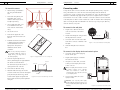
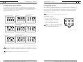
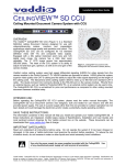
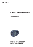
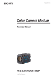
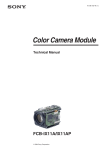
Ceiling DocCam™ II User Manual
ClearOne Communications, Inc. ~ 1825 Research Way, Salt Lake City, UT 84119 ~ tel 1-800-945-7730 ~ fax 1-800-933-5107
ii
Ceiling DocCam II — Table of Contents
1
Ceiling DocCam II — Introduction
Table of Contents
Introduction
Introduction . . . . . . . . . . . . . . . . . . . . . . . . . . . . . . . . . . . . . . . . . . . . . . . . . . . .1
The Ceiling DocCam™ II is a ceiling-mounted document camera that displays images on
monitors, plasma screens, video projectors and videoconferencing systems. It is ideal for
presenting or sharing any type of object or document, from detailed images to large
blueprints. The camera is installed in the ceiling above a conference table and has a low
profile design that is appropriate for any room decor. Additional features include:
Services and support . . . . . . . . . . . . . . . . . . . . . . . . . . . . . . . . . . . . . . . . . . . . . . . . . . . . .1
Product returns . . . . . . . . . . . . . . . . . . . . . . . . . . . . . . . . . . . . . . . . . . . . . . . . . . . . . . . . .1
Unpacking . . . . . . . . . . . . . . . . . . . . . . . . . . . . . . . . . . . . . . . . . . . . . . . . . . . . . . . . . . . . .2
Important safeguards . . . . . . . . . . . . . . . . . . . . . . . . . . . . . . . . . . . . . . . . . . . . . . . . . . . .3
Product overview . . . . . . . . . . . . . . . . . . . . . . . . . . . . . . . . . . . . . . . . . . . . . . . . . . . . . . .4
Installation . . . . . . . . . . . . . . . . . . . . . . . . . . . . . . . . . . . . . . . . . . . . . . . . . . . .7
Before you install . . . . . . . . . . . . . . . . . . . . . . . . . . . . . . . . . . . . . . . . . . . . . . . . . . . . . . .7
Mounting the camera . . . . . . . . . . . . . . . . . . . . . . . . . . . . . . . . . . . . . . . . . . . . . . . . . . . .7
Connecting cables . . . . . . . . . . . . . . . . . . . . . . . . . . . . . . . . . . . . . . . . . . . . . . . . . . . . . . .9
Configuring for remote controls . . . . . . . . . . . . . . . . . . . . . . . . . . . . . . . . . . . . . . . . . . . . .10
Programming presets . . . . . . . . . . . . . . . . . . . . . . . . . . . . . . . . . . . . . . . . . . . . . . . . . . . .11
Operation . . . . . . . . . . . . . . . . . . . . . . . . . . . . . . . . . . . . . . . . . . . . . . . . . . . . .12
Using your codec remote . . . . . . . . . . . . . . . . . . . . . . . . . . . . . . . . . . . . . . . . . . . . . . . . . .12
Using your ClearOne remote . . . . . . . . . . . . . . . . . . . . . . . . . . . . . . . . . . . . . . . . . . . . . . .12
Viewing areas . . . . . . . . . . . . . . . . . . . . . . . . . . . . . . . . . . . . . . . . . . . . . . . . . . . . . . . . . .13
Custom cable information . . . . . . . . . . . . . . . . . . . . . . . . . . . . . . . . . . . . . . . . . . . . . . . . .13
Troubleshooting . . . . . . . . . . . . . . . . . . . . . . . . . . . . . . . . . . . . . . . . . . . . . . . . .14
•
Laser pointer providing accurate document positioning.
•
Single cable carrying power, video and control, simplifying installation and
connection.
•
IR remote with increased functionality including zooming presets, brightness control and
laser operation.
•
User accessible DIP switches that allow the Ceiling DocCam II to respond to different
video codec remotes.
Services and support
If you need additional information on how to install, set up or operate your Ceiling DocCam
II, please contact us. We welcome and encourage your comments so we can continue to
improve our products and better meet your needs.
Technical support
Sales and customer service
Tel:
1-800-283 5936 (USA) or
1-801-974-3760
Tel:
1-800-945-7730 (USA) or
1-801-975-7200
Fax:
1-801-977-0087
Fax:
1-800-933-5107 (USA) or
1-801-977-0087
E-mail:
Web:
[email protected]
www.clearone.com
E-mail:
[email protected]
Appendix . . . . . . . . . . . . . . . . . . . . . . . . . . . . . . . . . . . . . . . . . . . . . . . . . . . . . .15
Specifications . . . . . . . . . . . . . . . . . . . . . . . . . . . . . . . . . . . . . . . . . . . . . . . . . . . . . . . . . .15
Warranty . . . . . . . . . . . . . . . . . . . . . . . . . . . . . . . . . . . . . . . . . . . . . . . . . . . . . . . . . . . . . .16
FCC Part 15/ICES-003 Compliance . . . . . . . . . . . . . . . . . . . . . . . . . . . . . . . . . . . . . . . . .18
RS-232 control information . . . . . . . . . . . . . . . . . . . . . . . . . . . . . . . . . . . . . . . . . . . . . . .20
Product returns
All product returns require a return materials authorization (RMA) number. Please contact
ClearOne Technical Support before attempting to return your product. Make sure you return
all the items that shipped with your product.
Ceiling DocCam II™ User Manual
ClearOne Part No. 800-171-066 May 2004 (Rev. 1.0)
© 2004 ClearOne Communications, Inc. All rights reserved. No part of this document may be reproduced in any
form or by any means without written permission from ClearOne Communications. Printed in the United States
of America. ClearOne Communications reserves specific privileges. Other product names may be trademarks of
their respective owners. Information in this document is subject to change without notice.
Technical Services Group ~ 1-800-283-5936 (USA) ~ 1-801-974-3760
Technical Services Group ~ 1-800-283-5936 (USA) ~ 1-801-974-3760
2
Ceiling DocCam II — Introduction
Ceiling DocCam II — Introduction
Unpacking
Important safeguards
Ensure that you received the following parts:
•
Read and understand all instructions before using.
•
Do not operate the Ceiling DocCam II if the power cord is damaged or if the Ceiling
DocCam II has been dropped or damaged. A qualified service technician must examine the
Ceiling DocCam II before operating.
•
Do not attempt to take the Ceiling DocCam II apart.There are no user-serviceable
components inside.
•
Clean exterior of Ceiling DocCam II by wiping with a clean, damp cloth; do not use
abrasive chemicals.
•
Do not store or operate the Ceiling DocCam II under the following conditions:
Ceiling DocCam
Manual
Trim Ring
Camera Enclosure
Single Wallplate
~
A temperature above 104° F (40° C) or below 32° F (0° C)
~
Environments with high humidity
~
Dusty environments
~
In inclement weather
~
Under severe vibration
3
PWR
FLIP
DISPLAY
FREEZE
AUTO
FOCUS
ZOOM
IN
CAM
LASER
ZOOM
OUT
PRESETS
1
0
2
4
3
5
SET
NEG/INV
B/W
AUTO
-
+
BRIGHTNESS
25' S-video Cable
50' Cat. 5 Cable with
RJ-45 Jacks
BNC TO RCA
Adapter
Remote
Attention: Use only the power supply provided with the Ceiling DocCam II. Use of any
unauthorized power supply will void any and all warranties.
Attention: Laser radiation is present. To avoid eye damage, do not stare directly into laser
beam.
Tile Support Rail
Triple-A
batteries (2)
6-32 X 1/2 Oval
Head (White)
Power Supply
CAUTION
LASER RADIATION
DO NOT STARE INTO BEAM
Figure 1. Unpacking items
CLASS II LASER PRODUCT
Note: ClearOne is not responsible for product damage incurred during shipment. You must
make claims directly with the carrier. Inspect your shipment carefully for obvious signs of
damage. If the shipment appears damaged, retain the original boxes and packing material for
inspection by the carrier. Contact your carrier immediately.
Technical Services Group ~ 1-800-283-5936 (USA) ~ 1-801-974-3760
Technical Services Group ~ 1-800-283-5936 (USA) ~ 1-801-974-3760
4
Ceiling DocCam II — Introduction
5
Ceiling DocCam II — Introduction
Front and back wall plate connections
Product overview
Camera enclosure
E
C
B
B
15 VDC
C
Composite
Video
F
D
S-video
A
RS-232
A
G
E
Figure 3. Front and back wall plate
A. RJ-45 Connector. The RJ-45 jack connects to the RJ-45 connector on the camera
enclosure using a Cat. 5 cable.
B. 15 VDC.The 15 VDC power supply jack.
D
Figure 2. Front and back of camera enclosure and trim ring
A. Lens. The lens has motorized zoom capabilities up to 25X optical and 12X digital for a
total of 300X.
B. Positioning indicator/laser. The laser ensures proper document orientation by indicating
where a document should be placed for best viewing. Laser displays for five seconds when
camera is first powered on.
Attention: Laser radiation is present. To avoid eye damage, do not stare directly into laser
beam.
C. Camera enclosure. This metal enclosure houses the camera electronics.
D. DIP switches.These are user configurable switches for specific third party remotes.
C. Composite. This output jack allows the Ceiling DocCam II to be connected to video display
devices that require a composite signal such as codecs,TV monitors, VCRs and LCD and
DLP projectors.
D. S-video. This output jack allows the Ceiling DocCam II to be connected to video display
devices that require an S-video signal such as video conferencing systems, video capture
cards,TVs and video to USB adapters. If your video display device has both S-video and
composite, use S-video for the highest quality image.
Both the S-video and composite outputs are always live making it possible to connect the
camera to two separate display devices at the same time.
E. RS-232. This output allows you to connect the camera to control systems such as Crestron
or AMX.
E. RJ-45 connector. This connector provides S-video, composite video, RS-232 and power to
the rear of the wall plate using the provided 50' Cat. 5 plenum-rated cable.
F. Threaded inserts. These inserts enable attachment to a standard electrical box (not
provided) using standard conduit connectors.
G. Trim ring.The trim creates a finished look when the camera is installed and holds the
camera and tile together.
Technical Services Group ~ 1-800-283-5936 (USA) ~ 1-801-974-3760
Technical Services Group ~ 1-800-283-5936 (USA) ~ 1-801-974-3760
6
Ceiling DocCam II — Introduction
Remote
7
Ceiling DocCam II — Installation
Installation
M
Before you install
PWR
FLIP
A
The following equipment is needed for proper installation:
L
DISPLAY
K
B
FREEZE
AUTO
FOCUS
ZOOM
IN
C
CAM
LASER
D
ZOOM
OUT
J
0
1
2
3
4
5
String or plumb bob
•
Utility knife
•
Flathead screwdriver
Be sure to check above the ceiling tile where you plan to install the camera to make sure the
area is clear and that there is enough room for the Ceiling DocCam II and all of its
components. Use the string or plumb bob to align and center the camera directly above the
viewing area. Use the utility knife to cut a hole in the tile and the screwdriver to attach the
white trim ring to the camera enclosure.
PRESETS
E
•
SET
F
NEG/INV
G
H
B/W
AUTO
-
Mounting the camera
I
+
BRIGHTNESS
Figure 4. ClearOne remote
The Ceiling DocCam II is an integrated document/object camera designed to be installed in a
suspended ceiling above a table. Recommended ceiling heights are between 8 and 12 feet.
The camera module enclosure and the tile support rail allow for exceptional positioning freedom when used with 2'x2' and 2'x4' ceiling tiles. The camera may be used with any tile 2'
wide. The tile support rail distributes the weight of the camera into the grid and prevents tile
warping. The diagram in Figure 5 shows the completed installation.
A. Flip. Rotates image 180º on video display device.
50' Cat 5 cable
B. Freeze. Freezes current image until you press again to release and return to live view.
C. Focus. Focus Near for close up views. Focus Far for distance views.
D. Cam Laser. Displays a laser pointer with momentary on (5 seconds) and auto off. Use the
laser pointer to position documents directly under the camera.
E. Presets. Stores up to six programmed camera setting presets (O-5).
F. Set. Press to program presets.
G. Neg/Inv. Makes image a negative.This is useful in hiding highlighted portions of documents,
by making them appear not highlighted.
H. Brightness. Auto automatically adjusts brightness, (+) manually brightens image and
(-) manually dims image.
I. B/W. Black/White displays image in black and white.
J. Zoom. Zoom In zooms for small images such as a stamp. Zoom Out zooms out for large
images or documents such as a blueprint.
Power
adapter
25' S-video
cable
Television
or
RS-232
Video Codec
K. Auto Focus. Automatically focuses an image.
L. Power.Turns the camera on or off.
M. Display. Shows icons for all camera controls and any messages associated with the presets.
Technical Services Group ~ 1-800-283-5936 (USA) ~ 1-801-974-3760
Serial Control Panel
Figure 5. Complete installation
Technical Services Group ~ 1-800-283-5936 (USA) ~ 1-801-974-3760
8
Ceiling DocCam II — Installation
9
Ceiling DocCam II — Installation
To mount the camera
Connecting cables
1. Attach a string or plumb bob to
the ceiling tile with a thumb
tack.
A single RJ-45 cable connects to the back of the wall plate providing S-video, composite
video, power and RS-232 control. The front of the wall plate provides the break-out
connections for S-video, composite video, power and RS-232 control. The wall plate may be
attached to a standard single gang wall box or placed in an equipment rack in a surface
mount wall box A 50' Cat. 5 cable is included to connect the camera enclosure to the back
of the wall plate. It is best to use the included Cat. 5 cable. In situations where a third party
cable is necessary, the cable must be between 10' and 200' long. Using a longer cable may
cause the camera to lose power.
2. Position the string directly over
ample table space or work
surface to allow easy document
and object positioning.
3. Using a sharp utility knife, score
a 31/2" diameter hole into the
front of the tile centered on the
string.
To connect to the wall plate
Figure 6. Positioning the camera
1
4. Cut out the 3 /2" hole.
5. Place the tile support rail on the
back side of the tile and center over
the hole.
2. Feed the wire through the ceiling to where
the wall plate will be connected.
3. Connect the other end of the Cat. 5 cable
to the RJ-45 connector on the back of the
wall plate.
6. Rotate the camera enclosure module
so that the positioning indicator is
oriented toward the monitor or
display device.This position is
standard document camera
orientation.
Ceiling DocCam
Cat. 5 cable
S-video, composite,
control and power signals
Wall Plate (back)
Figure 9. Enclosure with back of wall plate
4. Install the wall plate into an electrical
box.
To connect to the display device and control system
1. Connect the 15 VDC power supply plug
into the 15 VDC jack.
Figure 7. Support braces on 2'x2' ceiling tile
7. Fit the tile ring through the hole in
the tile, sandwiching the tile support between
the camera enclosure and the tile.
The camera tile ring will fit into the 31/2"
opening from the rear of the tile.
Enclosure
Ceiling Tile
8. Position the tile above the ceiling.
9. Attach the white trim ring to the camera
enclosure from the front of the tile and tighten
gently.This will pull the trim ring, camera
module and tile support rail together and
firmly hold the camera in position against the
ceiling tile.
Trim Ring
Figure 8. Enclosure and trim ring side view
Technical Services Group ~ 1-800-283-5936 (USA) ~ 1-801-974-3760
2. Plug the power supply into a standard
wall outlet (100V-240V).
3. Using the 25' S-video cable, connect the
S-video jack to the display device at the
S-video connector.
25' S-video
Note: If the positioning indicator is
not oriented toward the monitor or
display device, your image will not
be oriented properly.
1. Plug the Cat. 5 cable into the RJ-45
connector on the rear of the camera
enclosure.
Note: For display devices that do not have
an S-video connector, use a composite
cable (not included) to connect the
composite jack to the composite connector
on your display device.
4. Connect a serial cable to the control
system, if needed.
Attention: Use only the power supply
provided with the Ceiling DocCam II. Use
of any unauthorized power supply will void
warranty.
Figure 10. Connection to a video codec
Technical Services Group ~ 1-800-283-5936 (USA) ~ 1-801-974-3760
10
Ceiling DocCam II — Installation
11
Ceiling DocCam II — Installation
Configuring for remote controls
Programming presets
The Ceiling DocCam II can be programmed to work with the remotes listed below. DIP
switches on the camera enclosure must be configured in order to work with these remotes.
See Figure 2 on page 4 for exact location of DIP switches. Use the following diagram to
program your Ceiling DocCam II correctly.
Presets are used to program defined positions of the camera into a simple, one button preset.
You can switch easily from a zoomed in position on a small document to a zoomed out
position for documents such as blueprints. This saves the hassle of zooming in and out when
presenting documents of a variety of sizes. You can program your ClearOne IR remote with
six different presets labeled 0-5.
ClearOne Ceiling DocCam II (ONLY)
OFF
Note: These presets will only work with the ClearOne IR remote.
Polycom VS-4000, ViewStation FX
ViewStation, VSX-7000
ClearOne V-There
OFF
To program a preset
OFF
1. Zoom in or out to desired view.
ON
ON
1
1=Off
2
2=Off
ON
3
4
1
2
3
4
1
3=Off
4=Off
1=On
2=On
3=On
4=On
1=On
PolyCom IPower 600 Set-top
PictureTel, and 900 Tower
PolyCom IPower 9000
OFF
ON
3
4
1
2
3
1=Off
2=Off
3=On
4=On
1=On
2=On
3=Off
4
4=Off
Sony, PCS1 Set-top, PCS1600 Set-top,
PCS6000 Codec, PTZ Camera
OFF
ON
1=Off
3. Press the selected preset button (0-5).
Note: If you want to reset a preset, just
program a new preset using that same number.
The new preset will override the old one.
PRESETS
0
1
2
3
4
5
SET
Figure 12. Presets
1
2
1=Off
2=On
3
3=On
4
4=Off
Aethra
OFF
ON
1
4=Off
ON
2
OFF
3=Off
4
OFF
1
Sony EVI-D100
2=Off
3
Tandberg
OFF
ON
2
2. Press the Set button once.The on-screen
notification will indicate "Set number."
ON
2
3
4
1
2
3
4
1
2
2=Off
3=On
4=Off
1=On
2=Off
3=On
4=Off
1=Off
2=Off
3
3=Off
4
4=On
Figure 11. DIP switch configurations
Note: For best performance of the VISCA™ (a trademark of Sony Corporation) commands, set
DIP switches to the ClearOne configuration when the camera is connected to the control port
of a codec.
Note: After changing the DIP switches, camera must be power cycled.
Technical Services Group ~ 1-800-283-5936 (USA) ~ 1-801-974-3760
Technical Services Group ~ 1-800-283-5936 (USA) ~ 1-801-974-3760
12
Ceiling DocCam II — Operation
13
Ceiling DocCam II — Operation
Viewing areas
Operation
Using your codec remote
The only function you can control on the Ceiling DocCam II from your codec remote is the
zoom in or zoom out. All other functions must be performed using the ClearOne remote.
Viewing area depends on the distance between the ceiling and the table. Use the following
tables to determine the maximum and minimum viewing areas of the Ceiling DocCam II for
distances of 5.5', 6.5' and 7.5'. (Most tables are about 2.5' and ceiling heights vary between
8', 9' and 10'). If the distance differs from the examples given, use the table to estimate the
viewing area. There is also a distance calculator available online at www.clearone.com.
Using your ClearOne remote
The ClearOne remote will function in all DIP switch configurations. Please refer to Figure 4
on page 6 for a complete list of remote buttons.
To zoom
1. Press the Zoom Out button to view large
documents.
W
T
Height
Width
Diagonal
Zoomed out max
2.90'
3.87'
4.84'
Zoomed in optical 25x
.13'
.17'
.21'
Zoomed in optical 25x digital 12x
.06'
.09'
.11'
Distance between the ceiling and table : 6.5'
2. Press the Zoom In button to view
documents up close.
Optical Zoom
Note: When the zoom indicator passes the
divider on the display bar, the camera
moves from optical zoom to digital zoom.
Optical zoom uses the optical lens to
enlarge the image. Digital zoom crops a
small section of the picture and then
enlarges it to screen size. This can leave
the zoomed in image looking pixelated.
Distance between the ceiling and table : 5.5'
Digital Zoom
W
T
Cursor
Divider
Zoom switches
from optical zoom
to digital zoom
W = Wide
T = Telescopic
Figure 13. Zoom display
To focus an image
Height
Width
Diagonal
Zoomed out max
3.43'
4.58'
5.72'
Zoomed in optical 25x
.15'
.20'
.25'
Zoomed in optical 25x digital 12x
.08'
.10'
.13'
Height
Width
Diagonal
Zoomed out max
3.96'
5.28'
6.60'
Zoomed in optical 25x
.17'
.23'
.29'
Zoomed in optical 25x digital 12x
.09'
.12'
.15'
Distance between the ceiling and table : 7.5'
1. Press the Auto Focus button to automatically focus the camera.
Custom cable information
2. Press the Focus Far button to manually focus a zoomed out view.
If you need a longer cable, for best
performance use a Cat. 5E or Cat. 6 cable
with a 200' maximum and 24 AWG. Use
the following pinouts for the Cat. 5 or Cat.
6 cable.
3. Press the Focus Near button to manually focus a zoomed in view.
To use the camera laser
1. Press the Cam Laser button.
8 7 6 5 4 3 2 1
8 7 6 5 4 3 2 1
2. Center document under laser.
The camera laser will turn off automatically after 5 seconds.
To adjust the brightness
1. Press the Auto button to have the camera automatically adjust the brightness of the
on-screen image.
8
Brown/White
4
Blue/White
2. Press the - button to manually dim the on-screen image.
7
White/Brown
3
White/Green
6
Green/White
2
Orange/White
3. Press the + button to manually brighten the on-screen image.
5
White/Blue
1
White/Orange
Figure 14. Cable pinouts
Technical Services Group ~ 1-800-283-5936 (USA) ~ 1-801-974-3760
Technical Services Group ~ 1-800-283-5936 (USA) ~ 1-801-974-3760
14
Ceiling DocCam II — Troubleshooting
Troubleshooting
Problem
Try this
Verify that the Cat. 5 is connected between the RJ-45 jack on the back of
the camera module enclosure and the RJ-45 jack on the back of the wall
plate.
No video image
Make sure the provided 15 VDC power supply is plugged into a wall outlet
and the 15 VDC jack on the wall plate.
Check the S-video or composite cables to verify they are properly
connected, ensure video display device is powered and make sure the display
device is set to the correct video source.
The IR remote
control does not
work
Appendix
Specifications
Dimensions (Height x Diameter)
Enclosure: 4.5" x 6.5" (11.43 x 16.51 cm)
Ceiling cutout: 31/2" (8.9 cm) diameter
Trim ring: 5.5" (14 cm) diameter white
Video Format
NTSC or PAL
Remove power supply plug from the 15 VDC jack on the wall plate. Wait a
few seconds and reinsert the power supply plug.
Image Sensor
1/6 Type Super
Video Output
S-video and composite video (concurrent)
Control
IR remote (Either ClearOne or Selectable),
VISCA and IP control with optional Rack
Mount Interface Kit
Pixels
Effective: Approx. 688,000
Horizontal Resolution
480+ TV lines
Control Interface
VISCA (TTL Signal Level; Baud Rate: 9.6Kbps,
19.2Kbps; Stop Bit: 1 Selectable)
Sensitivity
2.5 Lux
Wall Plate
S-video, composite video, power, RS-232
SNR (Min)
49 dB
Camera Features
White balance: Auto
Brightness: Auto/Manual
Backlight compensation: Auto
Iris: Auto
Shutter: Auto exposure
Focus: Auto/Manual
6 Presets
Laser (momentary-on for document positioning)
Image Freeze
Image Flip
Black and White (color off)
Pos/Neg - Negative Art
Focal Range
Infinity to 800mm (Telescopic) -35mm (Wide)
Technical Services Group ~ 1-800-283-5936 (USA) ~ 1-801-974-3760
Lens (Horizontal Angle)
45 degrees (wide end) to
2.0 degrees (telescopic end)
Zoom
Optical 25X zoom, f=2.4 mm (wide) to 60 mm
(tele), F1.6 to F2.7
Digital 12X (300X total with optical zoom)
Weight
4 lb (1.81 kg)
Verify fresh batteries are installed and positioned correctly.
When large documents, such as blueprints, are being viewed, the smallest
Can’t see an entire
details may not appear perfectly.The resolution only allows zoomed in
drawing/page clearly
images to be clear. However, in viewing normal size documents, details should
on the video screen
be clear.
15
Ceiling DocCam II — Appendix
Enclosure
Plenum-rated
Power
Power Supply: 15 VDC,
100-240 VAC, 50/60 HZ
Consumption: 1.0 mA
Operating Temperature
32° F to 122° F (0° C to 50° C)
Cables
50' (15.24 m) plenum Cat. 5 cable with RJ-45
connectors, 25' (7.62 m) S-video cable
Models
910-171-066
910-171-066-PAL
Technical Services Group ~ 1-800-283-5936 (USA) ~ 1-801-974-3760
16
Ceiling DocCam II — Appendix
17
Ceiling DocCam II —Appendix
Warranty
ClearOne Communications, Inc. (Manufacturer) warrants that this product is free of defects in both
materials and workmanship. Should any part of this product be defective, the Manufacturer agrees,
at its option, to:
• Repair or replace any defective part free of charge (except transportation charges) for a period
of two years from the date the end user is invoiced for the product, provided the end user returns
the product to ClearOne Communications or an authorized ClearOne dealer according to the
Product Return and Repair statement set forth below;
This warranty excludes assembled products not manufactured by the Manufacturer whether or not
they are incorporated in a Manufacturer product or sold under a Manufacturer part or model
number.
Product Return and Repair
1. Return to Seller if Purchased Through an Authorized Dealer
a. Proof of purchase date from reseller within warranty period must be provided by the end user.
b. Seller may, at its discretion, provide an immediate exchange or repair or may return the
unit to the Manufacturer for repair.
2. Return to Manufacturer
a. An RMA (return merchandise authorization) number must be issued to the end user from
ClearOne technical support.
b. The end user must return the product to ClearOne with proof of purchase (showing purchase
date) for a warranty claim, and display the RMA number on the outside of the shipping
package.
THIS WARRANTY IS VOID IF:
A. The product has been damaged by negligence, accident, act of God, or mishandling, or has not
been operated in accordance with the procedures described in the operating and
technical instructions; or,
NO OTHER WARRANTY, EXPRESS OR IMPLIED, INCLUDING WARRANTIES OF MERCHANTABILITY OR FITNESS FOR ANY PARTICULAR USE, APPLIES TO THE PRODUCT.
MANUFACTURER’S MAXIMUM LIABILITY HEREUNDER SHALL BE THE AMOUNT PAID
BY THE END USER FOR THE PRODUCT. No person or entity authorized to assume any obligation
or other liability in connection with the products. No action, regardless of form, arising out of or
relating to the product or this warranty, may be brought by end user more than two (2) years after
the cause of action has accrued.
Manufacturer shall not be liable for punitive, consequential, or incidental damages, expenses, or loss
of revenue or property, inconvenience, or interruption in operation experienced by the end user due to
a malfunction in the purchased product. No warranty service performed on any product shall extend
the applicable warranty period.
In case of unsatisfactory operation, the end user shall promptly notify the Manufacturer at the
address set forth below in writing, giving full particulars as to the defects or unsatisfactory
operation. Upon receipt of such notice, the Manufacturer will give instructions respecting the shipment of the product, or such other matters as it elects to honor this warranty as above provided.This
warranty does not cover damage to the product during shipping and the Manufacturer assumes no
responsibility for such damage. All shipping costs shall be paid by the customer.
This warranty extends only to the original end user and is not assignable or transferable.This
warranty is governed by the laws of the State of Utah, without regard to the conflicts of interests
provisions thereof.
ClearOne Communications, Inc.
1825 Research Way
Salt Lake City, Utah 84119
B. The product has been altered or repaired by other than the Manufacturer or an authorized service
representative of the Manufacturer; or,
C. Adaptations or accessories other than those manufactured or provided by the Manufacturer have
been made or attached to the product which, in the determination of the Manufacturer, shall have
affected the performance, safety or reliability of the product; or,
D. The product’s original serial number has been modified or removed.
Technical Services Group ~ 1-800-283-5936 (USA) ~ 1-801-974-3760
Technical Services Group ~ 1-800-283-5936 (USA) ~ 1-801-974-3760
18
Ceiling DocCam II — Appendix
19
Ceiling DocCam II — Appendix
FCC Part 15/ICES-003 Compliance
89/336/EEC "Electromagnetic Compatibility (EMC) Directive":
This equipment has been tested and found to comply with the limits for a Class A digital device,
pursuant to Part 15 of the FCC rules and Industry Canada ICES-003.These limits are designed to
provide reasonable protection against harmful interference when the equipment is operated in a
commercial environment.This equipment generates, uses, and can radiate radio frequency energy and,
if not installed and used in accordance with the instruction manual, may cause harmful interference
to radio communications. Operation of this equipment in a residential area is likely to cause harmful
interference, in which case the user will be required to correct the interference at his/her own
expense.
EN 55022: 1994 (Emissions)
Specification for limits and methods of measure
ment of radio interference characteristics of
information technology equipment
EN 61000-3-2:1995/A1/A2:1998
Part 3: Limits - Section 2: Limits for harmonic
current emissions.
EN 61000-3-3:1995
Section 3: Limitation of voltage fluctuations and
flicker in low voltage supply systems for equipment with
rated current up to and including 16 A
EN 55024: 1998 (Immunity)
Information technology equipment - Immunity
characteristic. Limits and methods of measurement
EN 61000-4-2: 1995/A1:1998
Electrostatic Discharge
Operation is subject to the following two conditions: (1) This device may not cause interference, and
(2) This device must accept any interference including interference that may cause undesired
operation of the device.
Changes or modifications not expressly approved by ClearOne Communications could void the user's
authority to operate the equipment.
European Compliance
This equipment has been approved in accordance with Council Directive 1999/5/EC "Radio
Equipment and Telecommunications Equipment". Compliance of the equipment with the Directive is
attested by the application of the CE mark on the equipment.
EN 61000-4-3: 1996/A1:1998
Radiated RF Immunity
EN 61000-4-4: 1995
Electrical Fast Transients
EN 61000-4-5: 1995
Lighting Surge
EN 61000-4-6: 1996
Conducted RF Immunity
EN 61000-4-11: 1994
Voltage Dips and Voltage Interruptions
73/23/EEC "Low Voltage Directive (LVD)":
IEC 60950-1: 2003
Safety of Information Technology Equipment, Including
Electrical Business Equipment
EC Declaration of Conformity
Application of Council Directive(s):
1999/5/EC Radio equipment and Telecommunications
Terminal Equipment (R&TTE) Directive
Manufacturer's Name:
ClearOne Communications
Manufacturer's Address:
1825 West Research Way
Salt Lake City, Utah 84119 U.S.A.
Model No.:
Ceiling DocCam II 910-171-066-PAL,
Standard(s) to which Conformity is declared:
Technical Services Group ~ 1-800-283-5936 (USA) ~ 1-801-974-3760
Manufacturer
Legal Representative in Europe
Signature
Signature
Roger J. Midgley
Martin Offwood
Full Name
Full Name
Project Manager
Managing Director EMEA North
Position
Position
Technical Services Group ~ 1-800-283-5936 (USA) ~ 1-801-974-3760
20
Ceiling DocCam II — Appendix
RS-232 control information
Note: For best performance of the VISCA commands, set DIP switches to the ClearOne
configuration when the camera is connected to the control port of a codec.
21
Ceiling DocCam II — Appendix
• Error message
When a command or inquiry command could not be executed or failed, an error message is
returned instead of the completion message.
90 61 01 FF
Message length error (>14 bytes)
Overview of VISCA
90 61 02 FF
Syntax Error
In VISCA a device that sends commands,such as a computer, is called the controller.The device that
receives commands such as a camera is called the peripheral device.The parameters of RS-232C are
as follows.
90 61 03 FF
Command buffer full
90 61 04 FF
Command Cancelled
90 61 05 FF
No socket (to be cancelled)
Communication speed: 9.6 kbps/19.2 kbps/38.4 kbps
90 61 41 FF
Command not executable
• Data bits: 8
Command execution cancel
• Start bit: 1
To cancel a command which has already been sent, send the IF_Clear command as the next
command.To cancel one of any two commands which have been sent, use the cancel message.
• Stop: 1
Cancel Packet
81 21 FF
• Non parity
Flow control using XON/XOFF and RTS/CTS, etc., is not supported.
Cancel
VISCA Communication Specifications
An error message will be returned for this command, but this is not a fault. It indicates that the
command has been cancelled.
Command and inquiry
VISCA Command/ ACK Protocol
• Command
Sends operational commands to the camera.
• Inquiry
Used for inquiring about the current state of the camera.
Inquiry
Command Packet
81 QQ RR ... FF
Command
General Command
Note
QQ1) = Command/Inquiry
RR2)= Category code
QQ = 01 (Command), 09 (Inquiry)
1)
Command Message
Reply Message
81 01 04 38 02 FF
(Example)
90 41 FF (ACK)+90 51 FF
(Completion)
90 42 FF 90 52 FF
Returns ACK when a command has been
accepted, and Completion when a
command has been executed.
81 01 04 38 FF
(Example)
90 60 02 FF (Syntax Error)
Accepted a command which is not
supported or a command lacking
parameters.
81 01 04 38 02 FF
(Example)
90 60 03 FF
(Command Buffer Full)
There are two commands currently being
executed and the command could
not be accepted.
81 01 04 08 02 FF
(Example)
90 61 41 FF
(Command Not Executable)
90 62 41FF
Could not execute the command in the
current mode.
81 09 04 38 FF
(Example)
90 50 02 FF (Completion)
ACK is not returned for the inquiry command.
81 09 05 38 FF
(Example)
90 60 02 FF (Syntax Error)
Accepted an incompatible command.
RR = (Interface), 04 (camera 1), 06 (Pan.Tilter), 07 (camera 2)
2)
Responses for commands and inquiries
• ACK Message
Returned by the camera when it receives a command. No ACK message is returned for inquiries.
• Completion message
Returned by the camera when execution of commands or inquiries is completed. In the case of
inquiry commands, it will contain reply data for the inquiry after the 3rd byte of the packet. If
the ACK message is omitted, the socket number will contain 0.
Ack
Completion (commands)
Completion (inquiries)
Inquiry Command
Comments
Address Set
88 03 01 FF
88 30 02 FF
Returned the device address to +1.
IF_Clear(Broadcast)
88 01 00 01 FF
88 01 00 01 FF
Returned the same command.
Reply Packet
IF_Clear (for x)
81 01 00 01 FF
z0 50 FF (Completion)
ACK is not returend for this command.
90 41 FF
90 51 FF
90 51 FF
Command Cancel
81 21 FF
z0 61 04 FF
(Command Canceled)
Returned when the command of the socket
specified is cancelled.
Completion for the command cancelled is
not returned.
z0 61 05 FF
Returned when the command of the specified
socket has already been completed or when
the scoket number specified is wrong.
Technical Services Group ~ 1-800-283-5936 (USA) ~ 1-801-974-3760
Technical Services Group ~ 1-800-283-5936 (USA) ~ 1-801-974-3760
22
Ceiling DocCam II — Appendix
VISCA Camera-Issued Messages
Command List
ACK/Completion Messages
Command Messages
23
Ceiling DocCam II — Appendix
Command Set
Command
Command Packet
Comments
Camera Power
On
81 01 08 01 01 FF
Power on
Off
81 01 08 01 00 FF
Power off
On
81 01 08 02 01 FF
Power on
Comments
Laser Power
ACK
z0 4y FF
(y:Socket No.)
Returned when the command is accepted.
Completion
z0 5y FF
(y: Socket No.)
Returned when the command has been executed.
z=Device address +8
Off
81 01 08 02 00 FF
Power off
Momentary
81 01 08 02 02 XX FF
XX=time on from
1 to 10 seconds
Address Set
Broadcast
88 30 01 FF
IF_Clear
Broadcast
88 01 00 01 FF
CommandCancel
Error Messages
Syntax Error
Command Buffer Full
Command Cancelled
No Socket
CAM_Zoom
81 2p FF
Stop
81 01 04 07 00 FF
Tele (Standard)
81 01 04 07 02 FF
81 01 04 07 03 FF
Command Messages
Comments
Wide (Standard)
90 60 02 FF
Returned when the command format is different
or when a command with illegal command
parameters is accepted.
Tele (Variable)
81 01 04 07 2p FF
Wide (Variable)
81 01 04 07 3p FF
Direct
81 01 04 47 0p 0q 0r 0s FF pqrs: Zoom Position
On
81 01 04 06 02 FF
Off
81 01 04 06 03 FF
Combine Mode
81 01 04 36 00 FF
Optical/Digital
Zoom Combined
Separate Mode
81 01 04 36 01 FF
Optical/Digital
Zoom Separate
90 60 03 FF
90 6y 04 FF
(1:Socket No.)
90 6y 05 FF
(1:Socket No.)
Command not executable 90 6y 41 FF
(1:Socket No.)
Indicates that two sockets are already being
used (executing two commands) and the
command could not be accepted when received.
CAM_DZoom
Returned when a command which is being
executed in a socket specified by the cancel
command is canceled. The completion message
for command is not returned.
Returned when no command is executed in a
socket specified by the cancel command, or
when an invalid socket number is specified.
Returned when a command cannot be executed
due to current conditions. For example, when
commands controlling the focus manually are
received during auto focus.
Stop
81 01 04 06 00 FF
Tele(Variable)
81 01 04 06 2p FF
Wide(Variable)
81 01 04 06 3p FF
x1/Max
81 01 04 06 10 FF
Direct
CAM_Focus
Network Change Message
Network Change
p: Socket No.(=1or2)
p=0 (Low) to 7 (high)
Digital zoom ON/OFF
p=0 (low) to 7 (high)
x1/Max Magnification
Switchover
81 01 04 46 00 00 0p 0q FF pq: D-Zoom Position
Stop
81 01 04 08 00 FF
Far (Standard)
81 01 04 08 02 FF
Near (Standard)
81 01 04 08 03 FF
Command Message
Comments
Far (Variable)
81 01 04 08 2p FF
z0 38 FF
Issued when power is being routed.
Near (Variable)
81 01 04 08 3p FF
Direct
81 01 04 48 0p 0q 0r 0s FF
pqrs: Focus Position
Auto Focus
81 01 04 38 02 FF
AF ON/OFF
Manual Focus
81 01 04 38 03 FF
AF Sensitivity
Technical Services Group ~ 1-800-283-5936 (USA) ~ 1-801-974-3760
p=0 (Low) to 7 (high)
Auto/Manual
81 01 04 38 10 FF
One Push Trigger
81 01 04 18 01 FF
One Push AF Trigger
Infinity
81 01 04 18 02 FF
Forced infinity
Near Limit
81 01 04 28 0p 0q 0r 0s FF
pqrs: Focus Near
Limit Position
Normal
81 01 04 58 02 FF
Low
81 01 04 58 03 FF
AF Sensitivity
High/Low
Technical Services Group ~ 1-800-283-5936 (USA) ~ 1-801-974-3760
24
Ceiling DocCam II — Appendix
Command Set
CAM _AF Mode
Command
Normal AF
Command Packet
Interval AF
81 01 04 57 00 FF
81 01 04 57 01 FF
Zoom Trigger AF
81 01 04 57 02 FF
Comments
Command Set
AF Movement Mode
CAM_ Gain
Active/Interval Time 81 01 04 27 0p 0q 0r 0s FF pq: Movement Time
rs: Interval
CAM_ZoomFocus
Direct
81 01 04 47 0p 0q 0r 0s
0t 0u 0v 0w FF
pqrs: Zoom Position
tuvw: Focus Position
CAM_Initialize
Lens
81 01 04 19 01 FF
Lens Initialization
Start
Comp Scan
81 01 04 19 02 FF
Correction of CCD
pixel blemishes
Auto
81 01 04 35 00 FF
Normal Auto
Indoor
81 01 04 35 01 FF
Indoor Mode
Outdoor
81 01 04 35 02 FF
Outdoor Mode
One Push WB
81 01 04 35 03 FF
ATW
81 01 04 35 04 FF
CAM_WB
CAM_RGain
CAM_BGain
CAM_AE
CAM_Shutter
CAM_Iris
81 01 04 0D 00 FF
Up
81 01 04 0D 02 FF
Down
81 01 04 0D 03 FF
Direct
81 01 04 4D 00 00 0p 0q FF pq: Bright Position
81 01 04 0E 02 FF
81 01 04 0E 03 FF
Direct
81 01 04 4E 00 00 0p 0q FF
pq: ExpComp Position
On
81 01 04 33 02 FF
Back Light
Compensation On/Off
Off
81 01 04 33 03 FF
On
81 01 04 59 02 FF
Off
81 01 04 59 03 FF
Position
81 01 04 29 0p 0q 0r 0s FF
pq: X (-toF)
rs: Y (0 to F)
Reset
81 01 04 02 00FF
Aperture Control
Up
81 01 04 02 02 FF
Down
81 01 04 02 03 FF
Direct
81 01 04 42 00 00 0p 0q FF
pq: Aperture Gain
CAM_LR_Reverse
On
81 01 04 61 02 FF
Mirror Image On/Off
Off
On
81 01 04 61 03 FF
81 01 04 62 02 FF
Manual Control of
R Gain
Down
81 01 04 03 03 FF
Direct
81 01 04 43 00 00 0p 0q FF
pq: R Gain
Reset
81 01 04 04 00 FF
Manual Control of
B Gain
CAM_ BackLight
CAM_SpotAE
CAM_Aperture
pq: B Gain
Automatic Exposure
Mode
Manual
81 01 04 039 03 FF
Manual Control Mode
Shutter Priority
81 01 04 39 0A FF
Shutter Priority
Automatic Exposure
mode
CAM_Freeze
Off
81 01 04 62 03 FF
Iris priority Automatic
Exposure mode
CAM_PictureEffect Off
81 01 04 63 00 FF
81 01 04 39 0B FF
Bright Setting
Down
81 01 04 03 00 FF
Iris Priority
CAM_SlowShutter
81 01 04 4C 00 00 0p 0q FF pq: Gain Position
Reset
Up
81 01 04 03 02 FF
81 01 04 39 00 FF
81 01 04 0C 03 FF
Direct
Auto Tracing White
Balance
Up
Full Auto
Down
Gain Setting
One Push WB Mode
Reset
81 01 04 44 00 00 0p 0q FF
81 01 04 0C 02 FF
81 01 04 0E 00 FF
One Push WB Trigger
Direct
81 01 04 0C 00 FF
Up
Reset
81 01 04 10 05 FF
81 01 04 04 02 FF
Reset
81 01 04 3E 03 FF
One Push Trigger
81 01 04 04 03 FF
Comments
Off
Manual Control mode
CAM_ExpComp
Command Packet
81 01 04 3E 02 FF
81 01 04 35 05 FF
Down
CAM_Bright
Command
On
Manual
Up
25
Ceiling DocCam II — Appendix
Bright
81 01 04 039 0D FF
Bright mode
(Manual Control)
Auto
81 01 04 5A 02 FF
CAM_ PictureFlip
Manual
81 01 04 5A 03 FF
Auto Slow Shutter
a)
On/Off
Reset
81 01 04 0A 00 FF
Shutter Setting a)
CAM_ICR
Up
81 01 04 0A 02 FF
Down
81 01 04 0A 03 FF
Direct
81 01 04 4A 00 00 0p 0q FF pq: Shutter Position
Reset
81 01 04 0B 00 FF
Up
81 01 04 0B 02 FF
Down
81 01 04 0B 03 FF
Direct
81 01 04 4B 00 00 0p 0q FF pq: Iris Position
CAM_ Auto ICR
Neg. Art
81 01 04 63 02 FF
B&W
81 01 04 63 04 FF
On
81 01 04 66 02 FF
Off
81 01 04 66 03 FF
On
81 01 04 01 02 FF
Off
81 01 04 01 03 FF
On
81 01 04 51 02 FF
Off
81 01 04 51 03 FF
Exposure
Compensation
ON/OFF
Exposure
Compensation
Amount Setting
Still Image On/Off
Picture Effect Setting
Picture Flip On/Off
Infared Mode On/Off
Auto Infared Mode
On/Off
Iris Setting
a) Some models do not support slow shutter.
Technical Services Group ~ 1-800-283-5936 (USA) ~ 1-801-974-3760
Technical Services Group ~ 1-800-283-5936 (USA) ~ 1-801-974-3760
26
Ceiling DocCam II — Appendix
Command Set
CAM_Stablizer
CAM_Memory
CAM_Custom
CAM_Display
Command
Command Packet
On
81 01 04 34 02 FF
Off
81 01 04 34 03 FF
Reset
81 01 04 3F 00 0p FF
Set
81 01 04 3F 01 0p FF
Recall
81 01 03 3F 01 0p FF
Reset
81 01 04 3F 00 7F FF
Set
Recall
81 01 04 3F 01 7F FF
81 01 04 3F 02 7F FF
On
81 01 04 15 02 FF
(81 01 06 06 02 FF)
81 01 04 15 03 FF
(81 01 06 06 03 FF)
Off
27
Ceiling DocCam II — Appendix
Comments
Command Set
Command
Vibration Correction
On/Off
CAM_PrivacyZone
SetMask
81 01 04 76 mm nn
0p 0p 0q oq 0r 0r 0s 0s FF
mm: Mask Settings
nn 00: Modify, 01: New
pp: X, qq: Y, rr: W, ss: H
Display
81 01 04 77 pp pp pp pp FF
Mask Display On/Off
pp pp pp pp : Mask
Settings (0: Off, 1: On)
SetMask Color
81 01 04 78 pp pp pp pp
qq rr FF
pp pp pp pp: Mask
Color Settings
qq: Color Setting when
0 is selected
rr: Color SEtting when
1 is selected
p: Memory Number
(=0 to 5)
Starts in this mode at
Power on
SetPan TiltAngle 81 01 04 79 0p 0p 0p
0q 0q 0q FF
Display On/Off
Move Pan Tilt
CAM_Title
CAM_Mute
CAM_VPhase
Command Packet
On/Off
81 01 04 15 10 FF
(81 01 04 06 06 10 FF)
Title Set 1
81 01 04 73 00 mm nn pp
qq 00 00 00 00 00 00 FF
mm: Vposition,
nn: Hposition, pp: Color
qq: Blink
Title Set 2
81 01 04 73 01 mm nn pp
qq rr ss tt uu vv ww FF
mnpqrstuvw: Setting of
Display Characters
1st to 10th Character
Title Set 3
81 01 04 73 02 mm nn pp
qq rr ss tt uu vv ww FF
mnpqrstuvw: Setting of
Display Characters
11st to 20 th Character
Title Clear
81 01 04 74 00FF
Title Setting Clear
On
81 01 04 74 02 FF
Title Display On/Off
Off
81 01 04 74 03 FF
On
81 01 04 75 02 FF
Off
ON/Off
81 01 04 75 03 FF
81 01 04 75 10 FF
Stop
81 01 04 05 00 FF
Up
81 01 04 05 02 FF
Down
81 01 04 05 03 FF
Up (Step)
81 01 04 08 2p FF
Down (Step)
81 01 04 05 3p FF
Reset
81 01 04 05 40 FF
Direct
81 01 04 45 00 00 0p 0q FF pq: V-Phase (00-FF)
Set PTzMask
CAM_KeyLock
81 01 04 7B mm 0p 0p 0p
0q 0q 0q 0r 0r 0r FF
81 01 04 7C 02 FF
GridOff
81 01 04 7C 03 FF
Off
81 01 04 17 00 FF
Mute On/Off
pqrs: Camera ID
(=0000 to FFFF)
81 01 04 55 00 FF
Internal Mode
81 01 04 55 01 FF
Line Lock mode
On
81 01 04 6B 02 FF
Alarm On/Off
Off
81 01 04 6B 03 FF
SetMode
81 01 04 6C pp FF
PP: Mode Settings
00 Focus Move Detection
(The rest position is fixed.)
01 Focus Move Detection
(The rest position is reset.)
02 AE Move Detection
(The rest value is fixed.)
01 AE Move Detection
(The rest value is reset.)
SetTime
81 01 04 6D 0p 0p FF
pp: Reset Time Setting
Alarm (Reply)
90 07 04 6B 01 FF
Detect Level
"Low" to "High"
90 07 04 6B 00 FF
Detect Level
"High" to "Low"
Restore factory settings
81 01 04 25 00 FF
No Phase Turnover
81 01 04 25 01 FF
Phase Turnover
CAM_ExternalLock INT
81 01 04 55 00 FF
LIne Lock
Technical Services Group ~ 1-800-283-5936 (USA) ~ 1-801-974-3760
Camera Control
Enable/Disbale
81 01 04 22 0p 0q 0r 0s FF
p=step (1-7)
180 degree
Grid Display On/Off
Line Lock
CAM_ExternalLock INT
0 degree
Pan/Tilt/Zoom Settings
for Mask
ppp:Pan, qqq: tilt
rrr: zoom
81 01 04 17 02 FF
CAM_IDWrite
CAM_Alarm
Pan/Tilt Angle Settings
ppp: Pan
qqq: Tilt
pp: Pan Speed
81 01 04 7A 0p 0p 0q 0q rs FF qq: Tilt Speed
r 0: Stop, 1: Right,
2: Le ft
s 0: Stop, 1: Up,
2: Down
GridOn
On
Comments
81 01 04 55 01 FF
Technical Services Group ~ 1-800-283-5936 (USA) ~ 1-801-974-3760
28
Ceiling DocCam II — Appendix
Inquiry Command
29
Ceiling DocCam II — Appendix
Inquiry Command
Command Packet
Inquiry Packet
Comments
81 09 04 29 FF
90 50 0p 0q 0r 0s FF
Inquiry Command
Command Packet
Inquiry Packet
Comments
CAM_SpotAE PosInq
Camera Power
81 09 08 01 FF
90 50 00 FF
Off
CAM_ApertureInq
81 09 04 42 FF
90 50 00 00 0p 0q FF
pq: X position
rs: Y position
pq: Aperture Gain
90 50 01 FF
On
81 09 04 61 FF
90 50 02 FF
On
90 50 00 FF
Off
On
CAM_LR_Reverse
ModeInq
CAM_FreezeModeInq
81 09 04 62 FF
90 50 03 FF
90 50 02 FF
90 50 03 FF
Off
On
Off
90 50 00 FF
90 50 02 FF
Off
Neg.Art
90 50 04 FF
B&W
90 50 02 FF
On
Laser Power
81 09 08 02 FF
90 50 01 FF
90 50 02 XX FF
On Momentary with
XX s left
CAM_PowerInq
81 09 04 00 FF
90 50 02 FF
On
90 50 03 FF
Off
CAM_ZoomPosInq
81 09 04 47 FF
90 50 0p 0q 0r 0s FF
pqrs: Zoom Position
CAM_DZoomModInq
81 09 04 06 FF
90 50 02 FF
D-Zoom on
90 50 03 FF
D-Zoom Off
90 50 00 FF
Combine Mode
90 50 01 FF
Separate Mode
CAM_DZoomC/SModInq
81 09 04 36 FF
CAM_PictureEffectModeInq 81 09 04 63 FF
CAM_PictureFlipModeInq 81 09 04 66 FF
90 50 03 FF
Off
90 50 02 FF
On
CAM_ICRModeInq
81 09 04 01 FF
90 50 03 FF
Off
CAM_AutoICRModeInq
81 09 04 51 FF
90 50 02 FF
On
90 50 03 FF
Off
CAM_StabilizerModeInq
81 09 04 34 FF
90 50 02 FF
90 50 03 FF
On
Off
90 50 pp FF
pp: Last Recall
Memory No.
CAM_DZoomPosInq
81 09 04 46 FF
90 50 00 00 0p 0q FF
pq: D-Zoom Position
CAM_FocusModeInq
81 09 04 38 FF
90 50 02 FF
Auto Focus
90 50 03 FF
Manual Focus
CAM_FocusPosInq
81 09 04 48 FF
90 50 0p 0q 0r 0s FF
pqrs: Focus Position
CAM_MemoryInq
81 09 04 3F FF
CAM_FocusNearLimitInq 81 09 04 28 FF
90 50 0p 0q 0r 0s FF
pqrs: Focus Near Limit
Position
CAM_DisplayModeInq
CAM_AFSensitivit9Inq
81 09 04 58 FF
90 50 02 FF
AF Sensitivity Normal
81 09 04 15 FF
90 50 02 FF
(81 09 06 06 FF) 90 50 03 FF
90 50 03 FF
AF Sensitivity Low
CAM_AFModInq
81 09 04 57 FF
90 50 00 FF
Normal AF
90 50 01 FF
Interval AF
90 50 02 FF
Zoom Trigger AF
CAM_AFTimeSettingInq
81 09 04 27 FF
90 50 0p 0q 0r 0s FF
pq: Movement Time
rs: Interval
CAM_WBModeInq
81 09 04 35 FF
90 50 00 FF
Auto
90 50 01 FF
In Door
90 50 02 FF
90 50 03 FF
Out Door
One Push WB
90 50 04 FF
ATW
90 50 05 FF
Manual
90 50 00 00 0p 0q FF
pq: R Gain
CAM_RGainInq
81 09 04 43 FF
CAM_BGainInq
81 09 04 44 FF
90 50 00 00 0p 0q FF
pq: B Gain
Cam AEModeInq
81 09 04 39 FF
90 50 00 FF
Full Auto
90 50 03 FF
Manual
90 50 0A FF
Shutter Priority
90 50 0B FF
Iris Priority
CAM_SlowShutterModeInq 81 09 04 5A FF
90 50 0D FF
Bright
90 50 02 FF
Auto
CAM_ShutterPosInq
81 09 04 4A FF
90 50 03 FF
90 50 00 00 0p 0q FF
Manual
pq: Shutter Position
CAM_IrisPosInq
81 09 04 4B FF
90 50 00 00 0p 0q FF
pq: Iris Position
CAM_GainPosInq
81 09 04 4C FF
90 50 00 00 0p 0q FF
pq: Gain Position
CAM_BrightPosInq
81 09 04 4D FF
90 50 00 00 0p 0q FF
pq: Bright Position
CAM_ExpCompModInq
81 09 04 3E FF
90 50 02 FF
On
90 50 03 FF
Off
CAM_ExpComPosInq
81 09 04 4E FF
90 50 00 00 0p 0q FF
pq: ExpCopm Position
CAM_BacklightModeInq
81 09 04 33 FF
90 50 02 FF
On
90 50 03 FF
Off
Technical Services Group ~ 1-800-283-5936 (USA) ~ 1-801-974-3760
CAM_TitleDisplayModeInq 81 09 04 74 FF
90 50 02 FF
On
Off
On
90 50 03 FF
Off
90 50 02 FF
On
CAM_MuteModeInq
81 09 04 75 FF
90 50 03 FF
Off
CAM_PrivacyDisplayInq
81 09 04 77 FF
90 50 pp pp pp pp FF
pp pp pp pp :
Mask Settings
(O:Off, 1: On)
CAM PrivacyPanTiltInq
81 09 04 79 FF
90 50 0p 0p 0p
0q 0q 0q FF
CAM_PrivacyPTZInq
81 09 04 7B mm FF 90 50 0p 0p 0p
0q 0q 0q 0r 0r 0r FF
CAM_KeyLockInq
81 09 04 17 FF
CAM_IDInq
81 09 04 22 FF
CAM_ExternalLockModeInq 81 09 04 55 FF
90 50 00 FF
ppp: Pan
qqq: Tilt
mm: Mask Settings
ppp: Pan
qqq: Tilt
rrr: Zoom
Off
90 50 02 FF
On
90 50 0p 0q 0r 0s FF
pqrs: Camera ID
90 50 00 FF
Internal Mode
90 50 01 FF
Line Lock Mode
90 50 00 FF
90 50 01 FF
90 50 00 00 0p 0q FF
0 degree
180 degree
pq: V-Phase Position
CAM_VPhaseSetInq
81 09 04 25 FF
CAM_VPhasePosInq
81 09 04 45 FF
CAM_VersionInq
81 09 00 02 FF
90 50 00 20
mn pq rs tu vw FF
mnpq: Model Code(04xx)
rstu:ROM Version
vw: Socket Number (=02)
CAM_AlarmInq
81 09 04 6B FF
CAM_AlarmModeInq
81 09 04 6C FF
90 50 02 FF
90 50 03 FF
90 50 pp FF
On
Off
pp: Alarm Mode
CAM_AlarmTimeInq
81 09 04 6D FF
90 50 0p 0p FF
CAM_AlarmDetectLevelInq 81 09 04 6E FF
90 50 01 FF
pp: Rest Position/
Value Reset Time
Detect Level "High"
81 09 04 59 FF
90 50 00 FF
90 50 02 FF
90 50 03 FF
On
Off
CAM_SpotAEModeInq
Detect Level "Low"
Technical Services Group ~ 1-800-283-5936 (USA) ~ 1-801-974-3760
30
Ceiling DocCam II — Appendix
31
Ceiling DocCam II — Appendix
Block Inquiry Command List
Lens Control System Inquiry Commands ... Command Packet 8x 09 7E 7E 00 FF
Byte
Bit
Comments
Byte
7
6
Destination Address
5
0
4
4
3
2
2
Byte
0
6
0
5
0
4
0
8
3
2
Source Address
Bit
Comments
Byte Bit
7
0
7
0
6
0
6
0
5
0
5
0
4
0
4
0
3
0
2
0
12
3
Zoom Position (LH)
Comments
2
Focus Position (HH)
1
1
1
0
0
0
0
0
0
0
0 Completion Message (50h)
7
0
7
0
7
6
1
6
0
6
0
6
5
0
5
0
5
0
5
4
1
4
0
4
0
3
0
3
2
0
2
5
9
13
3
Zoom Position (LL)
4
3
2
Focus Position (HL)
0
DZoomMode
1: Separate 0:Combine
0:
0:
1:
Normal
Interval
Zoom Trigger
0:
1:
0:
AF Sensitivity
1: Normal 0: Slow
2
Digital Zoom Mode 1: On 0: Off
1
Focus Mode
1
0
1
1
0
0
0
0
7
0
7
0
7
0
7
0
6
0
6
0
6
0
6
0
5
0
5
0
5
0
5
0
4
0
4
0
4
0
6
3
2
3
Comments
7
1
7
1
Bit
10
3
2
Zoom Position (HH)
14
3
2
Focus NearLimit (H)
1
1
1
0
0
0
1: Auto 0: Manual
0
4
3
2
Focus Position (LH)
1
0
0
Low Contrast Detection 1: Yes 0: No
Camera Memory Recall
1: Executing 0: Stopped
Focus Command
1: Executing 0: Stopped
Zoom Command
1: Executing 0: Stopped
7
0
7
0
7
0
7
6
0
6
0
6
0
6
1
5
0
5
0
5
0
5
1
4
0
4
0
4
0
3
2
7
3
Zoom Position (HL)
1
0
0
15
3
2
1
11
Focus Near Limit (L)
Technical Services Group ~ 1-800-283-5936 (USA) ~ 1-801-974-3760
2
1 Terminator (FFh)
4
1
3
1
2
1
1
1
1
0
0
1
Focus Position (LL)
Technical Services Group ~ 1-800-283-5936 (USA) ~ 1-801-974-3760
32
Ceiling DocCam II — Appendix
33
Ceiling DocCam II — Appendix
Camera Control System Inquiry Commands ... Command Packet 8x 09 7E 7E 01 FF
Byte
Bit
Comments
Byte
7
6
Destination Address
5
0
4
4
3
2
2
Byte
0
6
0
5
0
4
0
8
3
2
Source Address
Bit
Comments
Byte Bit
0
7
0
6
0
6
0
5
0
5
0
4
0
4
0
3
0
2
0
12
3
B Gain (H)
Comments
7
2
Focus Position (HH)
1
1
1
0
0
0
0
0
0
0
0 Completion Message (50h)
7
0
7
0
7
6
1
6
0
6
0
6
5
0
5
0
5
0
5
4
1
4
0
4
0
3
0
3
2
0
2
1
0
1
1
0
0
0
0
7
0
7
0
7
0
7
0
6
0
6
0
6
0
6
0
5
0
5
0
5
0
5
0
4
0
4
0
3
0
4
0
5
6
3
2
2
R Gain (H)
9
13
3
B Gain (L)
3
2
10
Focus Position (HL)
2
1
Focus Mode
14
4
3
2
Focus Position (LH)
1
0
0
0
0
6
Stabilizer (1:on, 0: off)
5
0
4
0
3
2
7
0
6
0
5
0
4
0
3
R Gain (L)
1
0
0
Aperture Gain
Technical Services Group ~ 1-800-283-5936 (USA) ~ 1-801-974-3760
1: Auto 0: Manual
0
Low Contrast Detection 1: Yes 0: No
Camera Memory Recall
1: Executing 0: Stopped
Focus Command
1: Executing 0: Stopped
Zoom Command
1: Executing 0: Stopped
1 Terminator (FFh)
7
0
7
6
0
6
1
5
0
5
1
4
0
15
3
2
1
11
1: Normal 0: Slow
Digital Zoom Mode 1: On 0: Off
1
7
AF Sensitivity
2
1
0
0
DZoomMode
1: Separate 0:Combine
0:
0:
1:
Normal
Interval
Zoom Trigger
0:
1:
0:
0
3
WB Mode
4
1
7
3
Comments
7
1
7
1
Bit
2
4
1
3
1
2
1
1
1
1
0
0
1
Focus Position (LL)
Technical Services Group ~ 1-800-283-5936 (USA) ~ 1-801-974-3760
34
Ceiling DocCam II — Appendix
35
Ceiling DocCam II — Appendix
Other Inquiry Commands ... Command Packet 8x 09 7E 7E 02 FF
Byte
Bit
Comments
Byte
7
6
Destination Address
5
0
4
4
3
2
2
Comments
Byte
Bit
Comments
7
0
7
0
6
0
6
0
6
0
5
0
5
0
5
0
4
0
4
0
8
4
12
3
2
B Gain (H)
3
2
Exposure Mode
1
0
0 Completion Message (50h)
Bit
0
1
Gain Position
1
0
0
7
0
7
0
7
0
6
1
6
0
6
0
6
0
5
0
5
0
5
0
5
0
4
1
4
0
4
0
3
0
3
2
0
2
1
0
1
0
0
0
7
0
7
0
7
0
7
0
6
0
6
0
6
0
6
0
5
0
5
0
5
0
5
0
4
0
4
0
4
0
3
0
5
6
3
2
2
R Gain (H)
1
7
6
B Gain (L)
10
Stabilizer (1:on, 0: off)
0
4
0
3
R Gain (L)
7
13
Spot AE 1: On 0: Off
3
2
Back Light 1: On 0: Off
2
1
Exposure Comp. 1:On 0: Off
1
0
Slow Shutter 1: Auto 2: Manual
0
14
4
2
WB Mode
4
3
3
Bright Position
3
2
Shutter Position
1
0
0
5
2
9
1
0
3
Byte
7
2
Source Address
0
1
Comments
3
1
7
Bit
Exposure Comp. Position
1
0
0
7
0
7
0
7
6
0
6
0
6
1
5
0
5
0
5
1
4
0
4
1
3
1
2
1
1
1
1
0
0
1
11
3
3
2
2
1
1
0
0
Aperture Gain
Technical Services Group ~ 1-800-283-5936 (USA) ~ 1-801-974-3760
15
4
Iris Position
1 Terminator (FFh)
Technical Services Group ~ 1-800-283-5936 (USA) ~ 1-801-974-3760
36
Ceiling DocCam II — Appendix
37
Ceiling DocCam II — Appendix
Enlargement Function Query Command ... Command Packet 8x 09 7E 7E 03 FF
Byte
Bit
Byte
Comments
Byte
Bit
6
0
6
0
6
0
5
0
5
0
5
0
4
0
4
0
4
0
3
0
2
0
4
4
8
2
12
3
3
Source Address
7
0
0
Destination Address
0
Comments
6
2
AF Activation Time (H)
SpotAE Position (X)
1
1
1
1
0
0
0
0
0
0
0
7
0 Completion Message (50h)
7
0
7
0
7
6
1
6
0
6
0
6
0
5
0
5
0
5
0
5
0
4
1
4
0
4
0
3
2
1
0
5
9
13
4
0
3
0
2
0
1
0
0
0
0
3
3
0
2
2
0
1
1
0
0
0
7
0
7
0
6
0
6
0
5
0
5
0
4
0
3
AF Activation Time (L)
7
0
7
6
0
6
0
5
0
5
0
4
0
4
0
6
0
10
3
3
Spot AE Position (Y)
14
4
0
0
3
0
0
2
0
1
1
1
Alarm (1:on, 0: Off)
1
0
0
0
0
Picture Flip (1:On, 0: Off)
0
0
2
3
Comments
7
2
2
Bit
7
3
1
Byte
Comments
7
5
0
Bit
2
Digital Zoom Position (H)
2
AF Interval Time (H)
7
0
7
0
6
0
6
0
5
0
5
0
4
0
4
0
7
11
7
0
7
1 Terminator (FFh)
6
0
6
1
5
0
5
1
4
0
4
1
0
3
1
15
3
3
3
2
2
2
Advanced Privacy (1: Provided 0: Not Provided)
2
1
1
Alarm (1: Provided 0: Not Provided)
1
1
0
Picture Flip (1:Provided, 0: Not Provided)
0
1
Digital Zoom Position (L)
1
1
0
0
AF Internval Time (L)
Technical Services Group ~ 1-800-283-5936 (USA) ~ 1-801-974-3760
Technical Services Group ~ 1-800-283-5936 (USA) ~ 1-801-974-3760
38
Ceiling DocCam II — Appendix
39
Ceiling DocCam II — Appendix
VISCA Command Setting Values
Exposure control
Exposure control
Shutter
Speed
NTSC
PAL
15
10000
10000
14
6000
13
28 dB
6000
0E
4000
3500
12
3000
2500
11
2000
1750
10
1500
1250
0F
1000
1000
0E
725
600
0D
500
0C
0E
7
10.5 dB
0D
6
9 dB
24 dB
0C
5
7.5 dB
F1.6
22 dB
0B
4
6 dB
1B
F1.6
20 dB
0A
3
4.5 dB
1A
F1.6
18 dB
09
2
3 dB
19
F1.6
16 dB
08
1
1.5 dB
18
F1.6
14 dB
07
0
0 dB
17
F1.6
12 dB
06
-1
-1.5 dB
1F
F1.6
28 dB
26 dB
1E
F1.6
26 dB
0D
24 dB
1D
F1.6
0C
22 dB
1C
0B
20 dB
0A
18 dB
Bright
IRIS GAIN
GAIN
IRIS
0F
Gain
Exposure
Comp.
09
16 dB
425
08
14 dB
350
300
07
12 dB
16
F1.6
10 dB
05
-2
-3 dB
0B
250
215
06
10 dB
15
F1.6
8 dB
04
-3
-4.5 dB
0A
180
150
05
8 dB
14
F1.6
6 dB
03
-4
-6 dB
09
125
120
04
6 dB
13
F1.6
4 dB
02
-5
-7.5 dB
08
100
100
4 dB
12
F1.6
2 dB
01
-6
-9 dB
07
90
75
11
F1.6
0
00
-7
10.5 dB
06
60
50
10
F2
0
05
30
25
04
15
12
03
8
6
02
4
3
01
2
00
1
03
02
Iris
+2 dB
01
0
00
-3 dB
0F
F2.4
0
0E
F2.8
0
0D
F3.4
0
0C
F4
0
0
11
F1.6
2
10
F2
0B
F4.8
1
0F
F2.4
0A
F5.6
0
0E
F2.8
09
F6.8
0
0D
F3.4
08
F8
0
0C
F4
07
F9.6
0
0B
F4.8
06
F11
0
0A
F5.6
05
F14
0
09
F6.8
04
F16
0
08
F8
03
F19
0
07
F9.6
02
F22
0
06
F11
01
F28
0
05
F14
00
CLOSE
0
04
F16
03
F19
02
F22
01
F28
00
CLOSE
Technical Services Group ~ 1-800-283-5936 (USA) ~ 1-801-974-3760
Technical Services Group ~ 1-800-283-5936 (USA) ~ 1-801-974-3760
40
Ceiling DocCam II — Appendix
Zoom Ratio and Zoom Position (for reference)
41
Ceiling DocCam II — Appendix
Lens Control
0000
x25-NTSC
Zoom Ratio Optical Zoom
x25 Lens
Position Data
x1
0000
x2
1781
Digital Zoom
Ratio
x25-PAL
Digital Zoom
Position Data
Digital Zoom
Position Data
x1
4000
4000
x2
5E00
5E80
x3
6800
6880
x3
213B
x4
6D00
6DC0
x4
2752
x5
7000
70C0
x5
2BB3
x6
7200
72C0
x6
2F03
x7
7380
7440
x7
315D
x8
7480
7540
x8
3364
x9
7580
7600
x9
34FF
x10
7600
76C0
x10
362C
x11
76C0
7740
x11
373D
x12
7700
77C0
x12
386A
x13
3929
x14
3A20
x15
3AfA
x16
3BBA
x17
3C5E
x18
3CCB
x19
3D70
x20
3DF8
x21
3E66
x22
3Ed3
x23
3F25
x24
x25
3F93
4000
Technical Services Group ~ 1-800-283-5936 (USA) ~ 1-801-974-3760
to
4000
to
7700 (77C0) a)
Zoom Position
Wide End
Optical Tele End
1000
to
Digital Tele End
C000
Focus Position
Near End
Far End
1000: Over Inf
2000: 7.2 m
3000: 3.3 m
4000: 2.0 m
5000: 1.3 m
6000: 1 m
7000: 80 cm
8000: 40 cm
9000: 20 cm
A000 11 cm
B000: 6 cm
C000: 3.5 cm
Focus
Near Limit
As the distance on the left
will differ dur to temperature
characteristics, etc., use as
approximate vaules.
* The lower 1 byte is fixed
at 00.
a) PAL
Others
R,B gain
00~FF
Aperture
00~0F
Title Setting
Vposition
00 to 0A
Hposition
00 to 17
00: Does not blink
Blink
01: Blinks
Color
00
White
01
Yellow
02
Violet
03
Red
04
Cyan
05
Green
06
Blue
Technical Services Group ~ 1-800-283-5936 (USA) ~ 1-801-974-3760